EP2675371B1 - Adjustable laparoscopic instrument handle - Google Patents
Adjustable laparoscopic instrument handle Download PDFInfo
- Publication number
- EP2675371B1 EP2675371B1 EP11808475.5A EP11808475A EP2675371B1 EP 2675371 B1 EP2675371 B1 EP 2675371B1 EP 11808475 A EP11808475 A EP 11808475A EP 2675371 B1 EP2675371 B1 EP 2675371B1
- Authority
- EP
- European Patent Office
- Prior art keywords
- handle
- pivot
- section
- surgical instrument
- working shaft
- Prior art date
- Legal status (The legal status is an assumption and is not a legal conclusion. Google has not performed a legal analysis and makes no representation as to the accuracy of the status listed.)
- Active
Links
- GDOPTJXRTPNYNR-UHFFFAOYSA-N CC1CCCC1 Chemical compound CC1CCCC1 GDOPTJXRTPNYNR-UHFFFAOYSA-N 0.000 description 1
Images


Classifications
-
- A—HUMAN NECESSITIES
- A61—MEDICAL OR VETERINARY SCIENCE; HYGIENE
- A61B—DIAGNOSIS; SURGERY; IDENTIFICATION
- A61B17/00—Surgical instruments, devices or methods, e.g. tourniquets
- A61B17/28—Surgical forceps
- A61B17/29—Forceps for use in minimally invasive surgery
- A61B17/2909—Handles
-
- A—HUMAN NECESSITIES
- A61—MEDICAL OR VETERINARY SCIENCE; HYGIENE
- A61B—DIAGNOSIS; SURGERY; IDENTIFICATION
- A61B17/00—Surgical instruments, devices or methods, e.g. tourniquets
- A61B17/04—Surgical instruments, devices or methods, e.g. tourniquets for suturing wounds; Holders or packages for needles or suture materials
- A61B17/06—Needles ; Sutures; Needle-suture combinations; Holders or packages for needles or suture materials
- A61B17/06061—Holders for needles or sutures, e.g. racks, stands
-
- A—HUMAN NECESSITIES
- A61—MEDICAL OR VETERINARY SCIENCE; HYGIENE
- A61B—DIAGNOSIS; SURGERY; IDENTIFICATION
- A61B17/00—Surgical instruments, devices or methods, e.g. tourniquets
- A61B2017/0042—Surgical instruments, devices or methods, e.g. tourniquets with special provisions for gripping
- A61B2017/00424—Surgical instruments, devices or methods, e.g. tourniquets with special provisions for gripping ergonomic, e.g. fitting in fist
-
- A—HUMAN NECESSITIES
- A61—MEDICAL OR VETERINARY SCIENCE; HYGIENE
- A61B—DIAGNOSIS; SURGERY; IDENTIFICATION
- A61B17/00—Surgical instruments, devices or methods, e.g. tourniquets
- A61B17/28—Surgical forceps
- A61B17/29—Forceps for use in minimally invasive surgery
- A61B17/2909—Handles
- A61B2017/291—Handles the position of the handle being adjustable with respect to the shaft
-
- A—HUMAN NECESSITIES
- A61—MEDICAL OR VETERINARY SCIENCE; HYGIENE
- A61B—DIAGNOSIS; SURGERY; IDENTIFICATION
- A61B17/00—Surgical instruments, devices or methods, e.g. tourniquets
- A61B17/28—Surgical forceps
- A61B17/29—Forceps for use in minimally invasive surgery
- A61B17/2909—Handles
- A61B2017/2912—Handles transmission of forces to actuating rod or piston
- A61B2017/2919—Handles transmission of forces to actuating rod or piston details of linkages or pivot points
- A61B2017/292—Handles transmission of forces to actuating rod or piston details of linkages or pivot points connection of actuating rod to handle, e.g. ball end in recess
-
- A—HUMAN NECESSITIES
- A61—MEDICAL OR VETERINARY SCIENCE; HYGIENE
- A61B—DIAGNOSIS; SURGERY; IDENTIFICATION
- A61B17/00—Surgical instruments, devices or methods, e.g. tourniquets
- A61B17/28—Surgical forceps
- A61B17/29—Forceps for use in minimally invasive surgery
- A61B2017/2947—Pivots
-
- A—HUMAN NECESSITIES
- A61—MEDICAL OR VETERINARY SCIENCE; HYGIENE
- A61B—DIAGNOSIS; SURGERY; IDENTIFICATION
- A61B90/00—Instruments, implements or accessories specially adapted for surgery or diagnosis and not covered by any of the groups A61B1/00 - A61B50/00, e.g. for luxation treatment or for protecting wound edges
- A61B90/70—Cleaning devices specially adapted for surgical instruments
Definitions
- This disclosure relates to adjustable surgical instrument handles by which improved ergonomic positions can be obtained. Specifically, this disclosure relates to surgical instruments with pivoting handle sections for improved ergonomics.
- the present disclosure relates to instruments with adjustable handles. While the present disclosure is made in the context of laparoscopic instruments for the purposes of illustrating the concepts of the design, it is contemplated that the present design and/or variations thereof may be suited to other types of surgical instruments, such as arthroscopic, endoscopic, orthopedic, neurologic, cardiologic, suture passing, stapling, or minimally invasive instruments, among others. Furthermore, the principles embodied in the present disclosure may be applicable outside the fields of surgery or medical devices.
- Laparoscopy is an established field of surgery, but opportunities remain for improvement to the instruments.
- Existing laparoscopic instruments may present significant challenges to a surgeon.
- the design of laparoscopic instruments may force a surgeon to place his hands, arms, and/or body in non-ergonomic, uncomfortable, and sometimes physically harmful positions.
- Articulated instrument tips have been introduced.
- the handle position and/or orientation may be altered in order to reposition and/or reorient the end effector.
- the handle position and/or orientation tends to be dependent on, or tied to, the end effector position and/or orientation.
- US 2007/0299469 discloses a laproscopic surgical device that includes a ratchet mechanism.
- the handle of the device is configured to manipulate a distal tool end of a laproscopic device.
- US 6,077,286 discloses an instrument having a shaft and a distal engaging element operated via a proximal actuator element integrated into a handle.
- the angle between the axis of the handle and the axis of the shaft can be varied and the handle is connected to the shaft via a universal joint.
- US 2001/027312 discloses an instrument with a handle which is able to undertake different positions during an operative procedure, thereby allowing comfortable or convenient positioning of the handle for the operative procedure being carried out.
- the present invention provides a surgical instrument for improved ergonomic positions including: a working shaft section at a distal end of the surgical instrument; a first pivot; a second pivot; and a handle section positioned at a proximal end of the surgical instrument comprising a first handle and a second handle, with the handle section pivotable relative to the working shaft section about the first pivot, wherein the first and second handles are pivotably connected to each other about the second pivot; wherein the first pivot comprises a pivot head portion comprising receiver slots on the surface of the pivot head portion, the receiver slots are configured to receive a locking member, characterised in that the locking member is connected to the handle section; wherein the first handle comprises a button slot for receiving a portion of a ratcheting mechanism, the button slot being positioned on a top surface of the first handle, and a projection portion extending from a proximal end of the first handle.
- the second handle comprises a head portion and a latch release cavity formed through the head portion, the latch release cavity being configured to receive a second handle pivot pin and allow the second handle pivot pin to move translationally within the latch release cavity, and the latch release cavity comprises a spring detent to bias the translational movement of the second handle pivot pin.
- the ratcheting mechanism includes a release member pivotably connected to a ratchet body and the ratchet body includes a first ramp, a second ramp is pivotably mounted to the second handle and the second ramp is angled toward the first ramp in a distal direction and away from the first ramp in a proximal direction, and a wedge member is disposed between the first ramp and the second ramp and the release member to interact with the first ramp and the second ramp, the wedge member being biased in a distal direction towards an end of the ratcheting mechanism and the release member being operable to force the wedge member in the proximal direction.
- Preferred embodiments are provided in the dependent claims.
- the second pivot is not coaxial with the first pivot.
- the surgical instrument further includes an end effector at a distal end of the working shaft section, wherein the end effector remains in a substantially constant functional state as the handle section pivots about the first pivot.
- the surgical instrument further includes an actuator engaged with the second handle and the end effector, the actuator is configured to actuate the end effector in response to moving the second handle relative to the first handle, wherein the actuator defines an actuation path length between the second handle and the end effector, and wherein the actuation path length remains substantially constant as the handle section pivots relative to the working shaft section about the first pivot such that the end effector remains in a substantially constant functional state as the handle section pivots about the first pivot.
- the first pivot includes a pivot housing with at least one pivot pin hole formed therein; at least one pivot pin; and at least one pivot pin hole formed in the first handle, wherein the pivot housing is pivotably connected to the first handle about the at least one pivot pin threaded through the at least one pivot pin hole of the first handle and the at least one pivot pin hole of the pivot housing.
- the first pivot further includes at least one stop pin slot formed in the pivot housing; at least one stop pin hole formed in the first handle; and at least one stop pin, wherein the at least one stop pin is threaded through the at least one stop pin hole formed in the first handle and into the at least one stop pin slot formed in the pivot housing, and wherein the size and shape of the at least one stop pin slots is configured to prevent the first handle from pivoting relative to the working shaft section beyond a predetermined angular range in either direction.
- the second pivot includes at least one second handle pivot pin hole formed in the first handle, wherein the second handle pivot pin is threaded through the at least one second handle pivot pin hole formed in the first handle and through the latch release cavity formed in the second handle to pivotably connect the second handle relative to the first handle.
- the present disclosure also describes an exemplary method for improved ergonomic stern surgery, the method including: providing a surgical instrument for improved ergonomics, the surgical instrument including: a working shaft section at a distal end of the surgical instrument; a first pivot; a second pivot; and a handle section at a proximal end of the surgical instrument including a first handle and a second handle, with the handle section pivotable relative to the working shaft section about the first pivot, and wherein the first and second handles are pivotably connected to each other about the second pivot; pivoting the handle section relative to the working shaft section about the first pivot; and pivoting the first and second handles relative to each other about the second pivot.
- the second pivot is not coaxial with the first pivot.
- the surgical instrument includes an end effector at a distal end of the working shaft section, wherein the end effector remains in a substantially constant functional state as the handle section pivots about the first pivot.
- the surgical instrument includes an actuator engaged with the second handle and the end effector, the actuator configured to actuate the end effector in response to moving the second handle relative to the first handle, wherein the actuator defines an actuation path length between the second handle and the end effector, and wherein the actuation path length remains substantially constant as the handle section pivots relative to the working shaft section through the first pivot.
- the first pivot includes a pivot housing having at least one pivot pin hole formed therein; at least one pivot pin; and at least one pivot pin hole formed in the first handle, wherein the pivot housing is pivotably connected to the first handle about the at least one pivot pin threaded through the at least one pivot pin hole of the first handle and the at least one pivot pin hole of the pivot housing.
- the first pivot further includes at least one stop pin slot formed in the pivot housing; at least one stop pin hole formed in the first handle; and at least one stop pin, wherein the at least one stop pin is threaded through the at least one stop pin hole formed in the first handle and into the at least one stop pin slot formed in the pivot housing, and wherein the size and shape of the at least one stop pin slots is configured to prevent the first handle from pivoting relative to the working shaft section beyond a predetermined angular range in either direction.
- a surgical instrument for improved ergonomic positions, including: a working shaft section at a distal end of the surgical instrument; a first pivoting means; a second pivoting means; and a handle section at a proximal end of the surgical instrument including a first handle and a second handle, with the handle section pivotable relative to the working shaft section about the first pivoting means, and wherein the first and second handles are pivotably connected to each other about the second pivoting means.
- the second pivoting means is not coaxial with the first pivoting means.
- the surgical instrument further includes an end effector at a distal end of the working shaft section, wherein the end effector remains in a substantially constant functional state as the handle section pivots about the first pivot.
- a surgical instrument for improved ergonomic positions, including: a working shaft section at a distal end of the surgical instrument; an end effector at a distal end of the working shaft section; a handle section at a proximal end of the surgical instrument; and a pivot section intermediate the working shaft section and the handle section, wherein the handle section is pivotable relative to the working shaft section and the end effector remains in a substantially constant functional state as the handle section pivots relative to the working shaft section, and wherein the handle section can be selectively positioned in at least three angled positions relative to the working shaft section.
- the surgical instrument has a longitudinal axis defined by the working shaft section, a handle section axis, and an angle ⁇ defining an angular relationship between the longitudinal axis and the handle section axis, wherein the handle section can be selectively positioned in an infinite number of angled positions relative to the longitudinal axis of the working shaft section over a range of angles defined by an angle ⁇ max and an angle ⁇ min .
- the handle section can be selectively positioned in multiple discrete angled positions ⁇ relative to the longitudinal axis of the working shaft section.
- the handle section can be selectively positioned in three discrete angled positions u relative to the longitudinal axis of the working shaft section.
- the three discrete angled positions ⁇ are about -35°, 0°, and 35°.
- ⁇ max is any number between about 0° and 180° and ⁇ min is any number between about 0° and -180°.
- ⁇ max is any number between about 0° and 90° and ⁇ min is any number between about 0° and -90°.
- the present disclosure describes an exemplary method for improved ergonomics during surgery, the method including: providing a surgical instrument for improved ergonomics, the surgical instrument including: a working shaft section at a distal end of the surgical instrument; an end effector at a distal end of the working shaft section; a handle section at a proximal end of the surgical instrument; and a pivot section intermediate the working shaft section and the handle section; and pivoting the handle section relative to the working shaft section, wherein the end effector remains in a substantially constant functional state as the handle section pivots, and wherein the handle section can be selectively positioned in at least three angled positions relative to the working shaft section.
- the method further includes: providing the surgical instrument for improved ergonomics, wherein the surgical instrument further includes: a longitudinal axis defined by the working shaft section; a handle section axis; and an angle ⁇ defining an angular relationship between the longitudinal axis and the handle section axis, wherein the handle section can be selectively positioned in an infinite number of angled positions relative to the longitudinal axis of the working shaft section over a range of angles defined by an angle ⁇ max and an angle ⁇ min ; selecting an angle position from the infinite number of angled positions between ⁇ max and an angle ⁇ min ; and pivoting the handle section to the selected angle position.
- the method further includes: providing the surgical instrument for improved ergonomics, wherein the surgical instrument further includes: a longitudinal axis defined by the working shaft section; a handle section axis; and an angle ⁇ defining an angular relationship between the longitudinal axis and the handle section axis, wherein the handle section can be selectively positioned in multiple discrete angled positions ⁇ relative to the longitudinal axis of the working shaft section; selecting a discrete angled position ⁇ from the multiple discrete angled positions; and pivoting the handle section to the selected discrete angled position ⁇ .
- the method further includes: providing the surgical instrument for improved ergonomics, wherein the handle section can be selectively positioned in three discrete angled positions; selecting one of the three discrete angled positions; and pivoting the handle section to the selected discrete angled position.
- Examples of the method or instrument may include one or more of the following features.
- the three discrete angled positions ⁇ are about -35°, 0°, and 35°.
- ⁇ max is any number between about 0° and 180° and
- ⁇ min is any number between about 0° and -180°.
- a surgical instrument for improved ergonomic positions, including: a working shaft section at a distal end of the surgical instrument; an end effector at a distal end of the working shaft section; a handle section at a proximal end of the surgical instrument; and means for pivoting the handle section relative to the working shaft section, wherein the end effector remains in a substantially constant functional state as the handle section pivots, and wherein the handle section can be selectively positioned in at least three angled positions relative to the working shaft section.
- the surgical instrument further includes a longitudinal axis defined by the working shaft section, a handle section axis, and an angle ⁇ defining an angular relationship between the longitudinal axis and the handle section axis, wherein the handle section can be selectively positioned in an infinite number of angled positions relative to the longitudinal axis of the working shaft section over a range of angles defined by an angle ⁇ max and an angle ⁇ min .
- the handle section can be selectively positioned in multiple discrete angled positions ⁇ relative to the longitudinal axis of the working shaft section.
- a surgical instrument for improved ergonomic positions, including: a working shaft section at a distal end of the surgical instrument; an end effector at a distal end of the working shaft section; and a handle section at proximal end of the surgical instrument, wherein the handle section includes a first handle having a proximal end, a distal end, two side surfaces, and a top surface, wherein the handle section is pivotable relative to the working shaft section, and wherein the end effector remains in a substantially constant functional state as the handle section pivots relative to the working shaft section.
- the top surface curves downward in the distal to proximal direction and has a spatulate shape.
- the top surface substantially lies along a radius of curvature.
- the radius of curvature is between about 2 and 4 inches (5.1 and 10.2 cm).
- the radius of curvature is between about 2.5 inches (6.4 cm) and 3.5 inches (8.9 cm).
- the radius of curvature is about 2.9 inches (7.4 cm).
- the top surface has a convex or rounded shape in the lateral direction between the two side surfaces.
- the top surface has a maximum width and a minimum width in the lateral direction between the two side surfaces.
- the minimum width of the top surface is located closer to the distal end of the first handle and the maximum width of the top surface is located closer to the proximal end of the first handle.
- the minimum width is between about 0.25 inches (0.64 cm) and about 0.75 inches (1.91 cm).
- the maximum width is between about 0.5 inches (1.3 cm) and about 1.25 inches (3.18 cm).
- the minimum width is about 0.5 inches (1.3 cm) and the maximum width is about 0.88 inches (2.24 cm).
- At least one of the two side surfaces further includes a thumb or finger rest area.
- the first handle further includes a finger loop.
- the first handle further includes a comfort material.
- the comfort material is silicone. The silicone comfort material is applied to the at least one of the first and second handles by an over-molding manufacturing process.
- the instrument further includes a second handle with at least one finger contact surface.
- the at least one finger contact surface substantially lies along a radius of curvature.
- the radius of curvature is between about 1.5 and 3.5 inches (3.8 and 8.9 cm).
- the radius of curvature is between about 2 inches (5.1 cm) and 3 inches (7.6 cm).
- the radius of curvature is about 2.5 inches (6.4 cm).
- the second handle further includes a finger loop having a first finger contact surface configured to receive the ring finger and the middle finger, a projection having a second finger contact surface configured to receive the pinky finger, and a recess portion having a third finger contact surface configured to receive the index finger, wherein the first and second finger contact surfaces substantially lie along a radius of curvature of about 2.5 inches (6.4 cm), and wherein the third finger contact surface is offset from the radius of curvature by about 0.0625 inches (0.159 cm).
- a surgical instrument for improved ergonomics including: providing a surgical instrument for improved ergonomics, the surgical instrument including: a working shaft section at a distal end of the surgical instrument; an end effector at a distal end of the working shaft section; and a handle section at a proximal end of the surgical instrument, wherein the handle section includes a first handle having a proximal end, a distal end, two side surfaces, and a top surface, wherein the handle section is pivotable relative to the working shaft section; and pivoting the handle section relative to the working shaft section, wherein the end effector remains in a substantially constant functional state as the handle section pivots relative to the working shaft section.
- the method may include one or more of the following features or methods.
- the top surface curves downward in the distal to proximal direction and has a spatulate shape.
- the top surface substantially lies along a radius of curvature.
- the radius of curvature is between about 2 and 4 inches (5.1 and 10.2 cm).
- the radius of curvature is between about 2.5 inches (6.4 cm) and 3.5 inches (8.9 cm).
- the radius of curvature is about 2.9 inches (7.4 cm).
- a surgical instrument for improved ergonomic positions, including: a working shaft section at a distal end of the surgical instrument; an end effector at a distal end of the working shaft section; a handle section at a proximal end of the surgical instrument, wherein the handle section includes a first handle having a proximal end, a distal end, two side surfaces, and a top surface; and means for pivoting the handle section relative to the working shaft section, wherein the end effector remains in a substantially constant functional state as the handle section pivots.
- the top surface curves downward in the distal to proximal direction and has a spatulate shape.
- the top surface substantially lies along a radius of curvature.
- the present disclosure also describes a surgical instrument for improved ergonomic positions, including: a working shaft section at a distal end of the surgical instrument; a handle section at a proximal end of the surgical instrument, with the handle section pivotable relative to the working shaft section; and a locking mechanism that prevents the handle section from pivoting relative to the working shaft section when the locking mechanism is engaged, and wherein the locking mechanism allows the handle section to pivot relative to the working shaft section when the locking mechanism is not engaged.
- the surgical instrument further includes: a pivot housing having a first locking surface; and a locking member having a second locking surface, wherein the first locking surface and the second locking surface are configured to engage with each other in a first state to lock the pivot section and prevent the handle section from pivoting relative to the working shaft section, and wherein the first locking surface and the second locking surface are configured to disengage with each other in a second state to unlock the pivot section and allow the handle section to pivot relative to the working shaft section.
- the surgical instrument further includes: a longitudinal axis defined by the working shaft section, a handle section axis, and an angle a defining an angular relationship between the longitudinal axis and the handle section axis, wherein the handle section can be selectively positioned in an infinite number of angled positions relative to the longitudinal axis of the working shaft section over a range of angles defined by an angle ⁇ max and an angle ⁇ min , and wherein the first and second locking surfaces are configured to lock at any angled position within the range of angles defined by ⁇ max and ⁇ min .
- Embodiments of the instrument may include one or more of the following features.
- the handle section can be selectively positioned in multiple discrete angle positions relative to the longitudinal axis of the working shaft section over a range of angles defined by an angle ⁇ max and an angle ⁇ min , and wherein the first and second locking surfaces are configured to lock in the multiple discrete angled positions within the range of angles defined by ⁇ max and ⁇ min .
- the first locking surface includes one or more teeth and the second locking surface includes one or more teeth configured to engage the one or more teeth of the first locking surface.
- the handle section can be selectively positioned in three discrete angled positions relative to the longitudinal axis of the working shaft section, and wherein the first and second locking surfaces are configured to lock in three discrete angled positions.
- the first locking surface includes three locking member receiver slots configured to receive a suitably shaped locking member to lock in each of the three discrete angled positions.
- the three discrete angled positions are about 35°, 0°, and -35°.
- At least one of the first locking surface and the second locking surface includes a frictional material that allows the first locking surface and the second locking surface to frictionally engage one another at any point and at any angle.
- a surgical instrument for improved ergonomics including: providing a surgical instrument for improved ergonomics, the surgical instrument including: a working shaft section at a distal end of the surgical instrument; and a handle section at a proximal end of the surgical instrument, with the handle section pivotable relative to the working shaft section, wherein the pivot section includes a locking mechanism that prevents the handle section from pivoting relative to the working shaft section when the locking mechanism is engaged, and wherein the locking mechanism allows the handle section to pivot relative to the working shaft section when the locking mechanism is not engaged; disengaging the locking mechanism to allow the handle section to pivot; pivoting the handle section to a desired angle position; and engaging the locking mechanism to prevent the handle section from pivoting.
- Examples of the method or instrument may include one or more of the following features.
- the surgical instrument further includes: a pivot housing including a first locking surface; and a locking member including a second locking surface, wherein the first locking surface and the second locking surface are configured to engage with each other in a first state to lock the pivot section and prevent the handle section from pivoting relative to the working shaft section, and wherein the first locking surface and the second locking surface are configured to disengage with each other in a second state to unlock the pivot section and allow the handle section to pivot relative to the working shaft section; disengaging the first locking surface and the second locking surface in the second state; pivoting the handle section to a desired angle position; and engaging the first locking surface and the second locking surface in the first state.
- the handle section can be selectively positioned in multiple discrete angle positions relative to the longitudinal axis of the working shaft section, and wherein the first and second locking surfaces are configured to lock in the multiple discrete angled positions.
- the first locking surface includes one or more teeth and the second locking surface includes one or more teeth configured to engage the one or more teeth of the first locking surface.
- the handle section can be selectively positioned in three discrete angled positions relative to the longitudinal axis of the working shaft section, and wherein the first and second locking surfaces are configured to lock in three discrete angled positions.
- the present disclosure describes a surgical instrument for improved ergonomic positions, including: a working shaft section at a distal end of the surgical instrument; a handle section at a proximal end of the surgical instrument; means for pivoting the handle section relative to the working shaft section; and locking means to prevent the pivoting means from pivoting the handle section relative to the working shaft section.
- the locking means includes: a first locking surface; and a second locking surface, wherein the first locking surface and the second locking surface are configured to engage with each other in a first state to engage the locking means to prevent the pivoting means from pivoting the handle section relative to the working shaft section, and wherein the first locking surface and the second locking surface are configured to engage with each other in a second state to disengage the locking means and allow the pivoting means to pivot the handle section relative to the working shaft section.
- the first locking surface includes one or more teeth and the second locking surface includes one or more teeth.
- a surgical instrument for improved ergonomic positions, including: a working shaft section at a distal end of the surgical instrument; an end effector at a distal end of the working shaft section; a handle section at a proximal end of the surgical instrument, wherein the handle section includes a first handle and a second handle; a pivot section intermediate the handle section and the working shaft section, wherein the handle section is pivotable relative to the working shaft section about the pivot section; and an actuator including a proximal end and a distal end, wherein the proximal end of the actuator is engaged with at least one of the first and second handles and the distal end of the actuator is coupled to the end effector such that moving the first and second handles relative to each other causes the actuator to affect the end effector.
- the actuator includes an elongated flexible member having a proximal end and a distal end, wherein the proximal end of the elongated flexible member engages the second handle and the distal end of the elongated flexible member engages the end effector.
- the elongated flexible member is a cable that can flex or bend laterally while substantially resisting longitudinal tension forces.
- the pivot section further includes a pivot pin with a guide hole formed through the pivot pin, the guide hole being configured to receive the cable therethrough and to substantially retain the cable along the centerline of the pivot section as the handle section articulates with respect to the working shaft section.
- the surgical instrument further includes a tension member configured to apply a substantially constant tension force to the cable.
- the tension member is a spring.
- the actuator includes two rigid portions connected by a flexible portion disposed between the two rigid portions, wherein the two rigid portions connected by the flexible portion substantially resist tension and compression forces applied in the longitudinal direction and allow the two rigid portions to articulate with respect to each other, so that the actuator can transmit tension and compression forces to the end effector while allowing the handle section to pivot.
- the surgical instrument further includes a working rod having a proximal end and a distal end, wherein the proximal end of the working rod is engaged with the distal end of the actuator, and wherein the distal end of the working rod is engaged with the end effector.
- the actuator includes: a first rigid portion; a second rigid portion; a first actuator pivot; a second actuator pivot; and a third actuator pivot, wherein the first actuator pivot engages the first rigid portion with the second handle, the second actuator pivot engages the first rigid portion with the second rigid portion, and wherein the third actuator pivot engages the second rigid portion to a stationary member.
- the second actuator pivot is substantially coaxial with the pivot section for at least one positional relationship between the first handle and the second handle.
- the mechanical advantage acting on the second rigid portion, through the first rigid portion corresponds to a ratio of about 10.
- a surgical instrument for improved ergonomics including: providing a surgical instrument for improved ergonomics, the surgical instrument including: a working shaft section at a distal end of the surgical instrument; an end effector at a distal end of the working shaft section; a handle section at a proximal end of the surgical instrument, with the handle section pivotable relative to the working shaft section about a pivot, and wherein the handle section includes a first handle and a second handle; and an actuator including a proximal end and a distal end, wherein the proximal end of the actuator is engaged with at least one of the first and second handles and the distal end of the actuator is coupled to the end effector such that moving the first and second handles relative to each other causes the actuator to affect the end effector; moving the first and second handles relative to each other to cause the actuator to affect the end effector.
- the actuator includes an elongated flexible member having a proximal end and a distal end, wherein the proximal end of the elongated flexible member engages the second handle and the distal end of the elongated flexible member engages the end effector.
- the elongated flexible member is a cable that can flex or bend laterally while substantially resisting longitudinal tension forces.
- the pivot further includes a pivot pin with a guide hole formed through the pivot pin, the guide hole being configured to receive the cable therethrough and to substantially retain the cable along the centerline of the pivot as the handle section articulates with respect to the working shaft section.
- a tension member configured to apply a substantially constant tension force to the cable.
- the present disclosure describes a surgical instrument for improved ergonomics during surgery including: a working shaft section at a distal end of the surgical instrument; an end effector at a distal end of the working shaft section; a handle section at a proximal end of the surgical instrument, wherein the handle section includes a first handle and a second handle; pivoting means to pivot the handle section relative to the working shaft section; and actuating means including a proximal end and a distal end, wherein the proximal end of the actuating means is engaged with at least one of the first and second handles and the distal end of the actuating means is coupled to the end effector such that moving the first and second handles relative to each other causes the actuating means to affect the end effector.
- the actuating means includes an elongated flexible member having a proximal end and a distal end.
- the actuating means includes: a first rigid portion; a second rigid portion; a first actuator pivot; a second actuator pivot; and a third actuator pivot, wherein the first actuator pivot engages the first rigid portion with the second handle, the second actuator pivot engages the first rigid portion with the second rigid portion, and wherein the third actuator pivot engages the second rigid portion to a stationary member.
- FIG. 1 shows an isometric view of a surgical instrument 100 having a working shaft section 174 at its distal end, a handle section 101 at its proximal end, and a pivot section 140 intermediate the working shaft section 174 and the handle section 101.
- the handle section 101 may include a first handle 102 and a second handle 122, as will be discussed in more detail below.
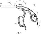
- FIG. 2 shows a side view of the surgical instrument 100 of FIG. 1 with the handle section 101 adjusted in a "drop-down" position relative to a longitudinal axis 183 of the working shaft section 174.
- the surgeon can use this handle orientation for high precision activities with his or her fingers in the finger loops 110, 130 to give the surgeon more precise control over an end effector (not shown) disposed at the distal end of the working shaft 182.
- an end effector not shown
- the surgical instruments disclosed herein can be used with any end effector, including, but not limited to: grasping jaws, dissectors, suture passers, staplers, tissue cutters, as well as any other end effector known in the art.
- adjusting the angular position of the handle section 101 relative to the working shaft section 174 will not affect the end effector. For example, if the end effector is grasping jaws, then adjusting the angular position of the handle section 101 relative to the working shaft section 174 will not cause the grasping jaws to open, close, rotate or otherwise move in any substantial manner. Moreover, the mechanical advantage of the grasping jaws would remain substantially constant as the handle section 101 pivots. The range of motion of the jaws, as well as the range of forces that can be applied to the jaws by the surgeon, would also remain substantially constant as the handle section 101 pivots.
- these embodiments allow for the ergonomic adjustment of the handle section 101 to improve the surgeon's comfort without interfering with the normal operation of the end effector.
- adjusting the angular position of the handle section 101 relative to the working shaft section 174 will not "substantially" affect the end effector.
- the end effector will substantially remain in the same functional state as the handle section 101 pivots, or will not deviate from the same functional state in an unsatisfactory manner, as the handle section 101 pivots.
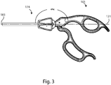
- FIG. 3 shows a side view of the surgical instrument 100 of FIG. 1 with the handle section 101 adjusted in an "in-line” position relative to the longitudinal axis 183 of the working shaft section 174.
- This handle orientation is similar to traditional "in-line” laparoscopic instruments such as needle holders.
- the "in-line” orientation may combine the best of both the “drop-down” and “in-line” configurations where the finger loops are still available for use in high precision tasks, such as grasping and positioning a needle, while also allowing the surgeon to grasp the handles in other ergonomic ways to perform different tasks that do not require as much precision, such as manipulating the needle inside of the patient.
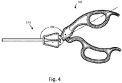
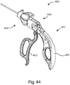
- FIG. 4 shows a side view of the surgical instrument 100 of FIG. 1 with the handle section 101 adjusted in an "angled-up" position relative to the working shaft section 174.
- This handle position orientation may provide the surgeon an ergonomically viable interface with the instrument 100 in the face of awkward approach angles to the patient, as dictated by the variable and unpredictable requirements of surgery.
- FIGS. 2-4 illustrate a reference system for measuring an angle a formed between the working shaft section 174 and the handle section 101.
- the reference system includes the longitudinal axis 183 corresponding to the working shaft section 174, a handle section axis 121 corresponding to the handle section 101, and an angle a defining the angular relationship between the longitudinal axis 183 and the handle section axis 121.
- the handle section axis 121 may be defined when the handle section 101 is positioned in the "in-line” position.
- the handle section axis 121 may be parallel to, or in-line with, the longitudinal axis 183.
- the angle ⁇ corresponds to 0°, as seen in FIG. 3 . If the handle section 101 is raised above the "in-line” position into an “angled-up” position, then the angle ⁇ is positive, as shown in FIG. 4 . If the handle section 101 is lowered from the "in-line” position into a “drop-down” position, then the angle ⁇ is negative, as illustrated in FIG. 2 .
- other reference systems or ways of measuring ⁇ can be used herein.
- the handle section 101 may have a limited pivot range with respect to the working shaft section 174 that is defined by an angle ⁇ max and an angle ⁇ min .
- the handle section 101 can pivot upward until the handle section 101 reaches ⁇ max , at which point the handle section 101 is prevented from pivoting upward any further.
- the handle section 101 can pivot downward until the handle section 101 reaches ⁇ min , at which point the handle section is prevented from pivoting downward any further.
- the pivot range of the handle section 101 may be limited to angles which lie between ⁇ max and ⁇ min .
- the handle section 101 can be selectively positioned and maintained in an infinite number of angled positions within the pivot range defined by the maximum angle ⁇ max and the minimum angle ⁇ min .
- the handle section 101 can be selectively positioned and maintained in multiple discrete angled positions within the pivot range between ⁇ max and ⁇ min . In yet other examples, the handle section 101 can be selectively positioned and maintained in three discrete angled positions within the pivot range between ⁇ max and ⁇ min . In a particular example, the handle section 101 can be selectively positioned and maintained in three discrete angled positions corresponding to about -35°, 0°, and 35°.
- the pivoting range of the handle section 101 may not be limited between a maximum angle ⁇ max and/or a minimum angle ⁇ min .
- some examples may have a maximum angle ⁇ max that is any number between 0° and 180° and/or a minimum angle ⁇ min that is any number between 0° and -180°.
- the maximum angle can be any number between 0° and 90° and the minimum angle can be any number between 0° and -90°.
- the maximum angle is about 35° and the minimum angle is about -35°.
- a practitioner may unlock the pivot section 140, select an angle position, rotate the handle section 101 relative to the working shaft section 175, until the desired angle position is reached, and relock the pivot section 140.
- FIG. 5 shows an exploded view of the surgical instrument 100 with its various components.
- FIGS. 6A-13C illustrate the individual components of FIG. 5 in greater detail. A detailed description of the structure and features for each individual component will be given in a generally proximal to distal direction with reference to FIGS. 6A-13C . A detailed description of how each of the individual components interrelate with one another will then be given, along with the functional relationships between each component. Exemplary methods of using the surgical instrument 100 will also be given to illustrate how a surgeon can utilize the surgical instrument 100 to achieve greater ergonomic postures during surgery.
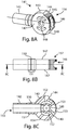
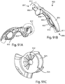
- FIGS. 6A-6C show various isometric views of a first handle 102, according to one example.
- the first handle 102 has a proximal end 196 and a distal end 197.
- the first handle 102 can have a top surface 105, a bottom surface 115, and two side surfaces 104.
- the top surface 105 can have a spatulate leaf shape and/or curve downward in the distal to proximal direction to better conform to the surgeon's palm.
- the top surface 105 can have a radius of curvature, or substantially lie along a radius of curvature.
- the radius of curvature can be between about 2 and 4 inches (5.1 and 10.2 cm).
- the radius of curvature can be between about 2.5 inches (6.4 cm) and 3.5 inches (8.9 cm).
- the radius of curvature is about 2.9 inches (7.4 cm).
- the top surface 105 of the first handle 102 may have a convex or rounded shape in the lateral direction between the two side surfaces 104 of the first handle 102.
- the top surface 105 is preferably shaped to be substantially wide enough between the two side surfaces 104 to provide adequate comfort to the surgeon's palm by providing sufficient surface contact area between the top surface 105 and the surgeon's palm to reduce or eliminate "hot spots" from forming on the surgeon's palm.
- the top surface 105 can have a maximum width and a minimum width in the lateral direction between the two side surfaces. In some embodiments, the minimum width of the top surface is located closer to the distal end of the first handle and the maximum width of the top surface is located closer to the proximal end of the first handle.
- the minimum width is between about 0.25 inches (0.64 cm) and about 0.75 inches (1.91 cm). In a particular embodiment, the minimum width is about 0.5 inches (1.3 cm). In some embodiments, the maximum width is between about 0.5 inches (1.3 cm) and about 1.25 inches (3.2 cm). In one embodiment, the maximum width is about 0.88 inches (2.2 cm).
- the location of the minimum width of the top surface can be chosen to correspond to the area of the top surface 105 that the surgeon's thumb traverses when the surgeon switches between a "finger loop" grip style and a "palm” grip style.
- Having the minimum width of the top surface in this area of the top surface 105 can allow the surgeon to more easily switch between the "finger loop” grip style and the "palm” grip style because the smaller width makes it easier for the surgeon's thumb to traverse this area of the handle.
- the top surface 105 may include a raised surface portion 119 to provide extra support for the surgeon's fingers or thumb in various different gripping styles.
- the side surfaces 104 may include a thumb or finger rest area 108 formed on or into the side surfaces 104 to provide extra support for the surgeon's thumb when engaged along the side surface 104.
- the first handle 102 may have one or more finger loop holes 110 to receive one or more fingers during procedures requiring greater precision.
- the finger loop hole contact surface 109 may be convex in shape and wide enough to avoid or eliminate any "hot spots" from occurring on the surgeon's fingers during extended hours of operation.
- the first handle 102 can have a projection portion 111 at the proximal end of the first handle 102.
- the projection portion 111 may provide greater surface area to interact with the surgeon's palm against the top surface 105, and also provide a concave-shaped projection recess portion 116 to interact with the surgeons fingers on the opposite side.
- the projection portion 111 can include an electrical connector to receive external input.
- the first handle 102 can also have a bottom surface 115 and a bottom surface recess area 114 having a concave shape configured to interact with one or more of the surgeon's fingers as needed.
- any or all of the surfaces of the first handle 102 may include a comfort material (not shown) attached to one or more of the surfaces of the first handle 102, such as a soft rubber, polymer, or silicone.
- the comfort material may be applied to the first handle 102 after manufacture, or the comfort material may be integrally formed or molded to the first handle 102 during manufacture by any suitable manufacturing processes including, but not limited to, bonding or over-molding.
- the distal end of the first handle 102 may include a head portion 112 for receiving a suitably shaped pivot housing 141 into a pivot housing slot 117.
- the head portion 112 may have stop pin holes 103 formed through both sides of the head portion 112 for receiving stop pins 168, as will be discussed in further detail below.
- the head portion 112 can have a pivot pin hole 106 formed through the head portion 112 configured to receive a pivot pin 164.
- the first handle 102 may include a pin hole 107 formed through, or substantially through, the side surfaces 104 of the first handle 102 and configured to receive a pivot pin 135 to pivotably secure a second handle 122.
- the surgical instrument 100 includes a dual pivot design with a first pivot connecting the handle section 101 to the working shaft section 174, and a second pivot connecting the second handle 122 to the first handle 102. Moreover, the first and second pivots are not coaxial with each other in this example.
- the first handle 102 may include a receiver slot 113 configured and shaped to receive the head portion 127 of a suitable second handle 122, as will be discussed in further detail below.
- FIG. 6C illustrates the pivot housing slot 117 configured to receive a suitable pivot housing 141 in greater detail.
- FIG. 6C also illustrates an actuator aperture 118 formed within the first handle 102 proximal to the head portion 112 and shaped to allow an actuator 170 to be disposed therein.
- the second handle 122 can have a proximal end 137 and a distal end 138.
- the second handle 122 can also have a top surface 126, a bottom surface 134, and two side surfaces 136. Each of the aforementioned surfaces may have a generally rounded or convex shape to increase comfort.
- the top surface 126 of the second handle 122 may have a slight "S-shaped" curvature formed therein moving in the distal to proximal direction.
- the distal end of the second handle 122 may include a head portion 127 configured to interact with the receiver slot 113 of the first handle 102, as shown in FIGS. 6A-6C .
- the second handle 122 may have one or more finger loop holes 130 configured to receive one or more of the surgeon's fingers during procedures that require greater precision.
- the inner contact surface 129 of the finger loop hole 130 may have a rounded or convex shape to comfortably engage the fingers of the surgeon.
- the second handle 122 may have at least one finger contact surface. Moreover, the at least one finger contact surface can be configured to substantially lie along a radius of curvature.
- the radius of curvature can be between about 1.5 and 3.5 inches (3.8 and 8.9 cm) in some embodiments. In other embodiments, the radius of curvature may be between about 2 inches (5.1 cm) and 3 inches (7.6 cm). In a particular embodiment, the radius of curvature is about 2.5 inches (6.4 cm).
- the second handle 122 can have a finger loop 130 defining a first finger contact surface 139 configured to receive the surgeon's ring finger and middle finger, a projection 132 configured to receive the surgeon's pinky finger, and a recess portion 188 having a third finger contact surface 128 configured to receive the surgeon's index finger.
- these finger contact surfaces can substantially lie along a radius of curvature.
- the first and second finger contact surfaces can substantially lie along a radius of curvature of about 2.5 inches (6.4 cm) and the third finger contact surface can be offset from the radius of the curvature of the first and second finger contact surfaces by about 0.0625 inches (0.159 cm).
- any or all of the surfaces of the second handle 122 may include a comfort/grip enhancing material (not shown) attached to one or more of the surfaces of the second handle 122, such as a soft rubber, polymer, or silicone material.
- the comfort/grip-enhancing material may be applied to the second handle 122 after manufacture, or alternatively the comfort/grip-enhancing material may be integrally formed or molded to the second handle 122 during manufacture by several manufacturing processes, such as, bonding or over-molding.
- the head portion 127 of the second handle 122 can have a latch release cavity 123 formed through the head portion 127.
- the latch release cavity 123 may have an oblong or elongated oval shape configured to receive a second handle pivot pin 135 to allow the second handle pivot pin 135 to move translationally within the latch release cavity 123.
- the latch release cavity 123 can have a spring detent 124 just below the latch release cavity 123 to help control and bias the translational movement of the second handle pivot pin 135, as will be discussed in greater detail below.
- the head portion 127 can have an actuator bore 133 formed through the head portion 127 and in communication with an actuator connection recess 125 on the opposite side of the head portion 127.
- the second handle 122 may comprise an alternative control member such as a trigger, a button, a lever, a truncated handle or any other structure suitable for a surgical instrument. In some examples, the second handle 122 may be omitted entirely.
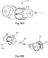
- FIGS. 8A-8C show a pivot housing 141.
- the pivot housing 141 may include a hollow shaft 142 at its distal end and a pivot head portion 156 at its proximal end.
- the pivot head portion 156 may have a top surface 143, a bottom surface 154, side surfaces 147, a top angled surface 144, and a bottom angled surface 149.
- the top surface 143 and the bottom surface 154 may have partially spherical shapes configured to receive a suitable rotation knob 175 and allow the rotation knob 175 to rotate freely about the pivot head portion 156.
- the pivot head portion 156 may include a pivot pin hole 148 formed through the pivot head portion 156 between the sides 147.
- the pivot head portion 156 may include stop pin slots 152 formed through the pivot head portion 156 having elongated and curved oval shapes.
- the pivot head portion 156 may also include one or more locking teeth 145 formed in a proximal surface of the pivot head portion 156.
- the hollow shaft 142 may have a larger diameter portion 151 wherein the larger diameter portion 151 may include an annular groove 150 formed therein.
- the annular groove 150 may be shaped and configured to receive a retaining pin 180 to allow the rotation knob 175 to rotate freely about the pivot housing 141, while keeping the rotation knob 175 from moving translationally with respect to the working shaft 182.
- the hollow shaft 142 can have an inner bore 155 shaped to receive a suitable restoring spring 173.
- the inner bore 155 may be in communication with the pivot pin hole 148 and a proximal opening 146 in the pivot head portion 156.
- the proximal opening 146 may open wider moving in the distal to proximal direction with diverging top and bottom surfaces 153.
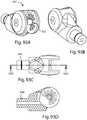
- FIG. 9 shows a locking member 158.
- the locking member 158 may have a locking surface 163 including one or more locking teeth 159 formed in a surface of the locking member 158 and configured to engage the locking surface 157 of the pivot housing 141, which can also include teeth 145, in some examples.
- FIG. 10 shows a connector 160.
- the connector 160 can have a bore 161 formed through the connector 160 and a radially chamfered surface formed in one end of the connector 160.
- FIGS. 11A-11C show various views of a pivot pin 164.
- the pivot pin 164 may have a guide hole 169 formed through the center of the pivot pin 164.
- the guide hole 169 can restrain the actuator 170 along the centerline of the joint as the handle section 101 pivots relative to the working shaft section 182.
- the guide hole 169 may have a distal end 166 and a proximal end 167 as shown in FIG. 11C .
- the distal end 166 of the guide hole 169 can be smaller in diameter than the proximal end 167 of the guide hole 169.
- the distal end 166 of the guide hole 169 can have a chamfered surface.
- the proximal end 167 of the guide hole 169 can also have a chamfered surface 165 which may be larger than the chamfered surface of the distal end 166 of the guide hole 169, as shown in FIGS. 11B and 11C .
- FIG. 12 shows one example of an actuator 170 that may be used in the present disclosure.
- the actuator 170 can have a distal connector 171 at its distal end and a proximal connector 172 at its proximal end.
- the distal connector 171 may have a partially spherical shape and a hollow center, as can be seen in FIG. 12 .
- the proximal connector 172 may have a solid spherical shape. However, it is to be understood that the proximal connector 172 and the distal connector 171 may assume any shape that can provide adequate operation of the actuator 170 according to the present disclosure.
- the actuator 170 may be formed of a flexible material to allow the actuator 170 to bend along its length when the handle section 101 pivots relative to the working shaft section 174.
- the actuator 170 can preferably be formed of a material that substantially resists tension forces that are applied to the actuator 170 between the distal connector 171 and proximal connector 172.
- the actuator 170 may be an elongated flexible member or a cable.
- the actuator 170 may be made of a rigid or semi-rigid segmented linkage that can be restrained to the centerline of the joint.
- the actuator 170 may be two rigid portions connected by a flexible portion disposed between the two rigid portions.
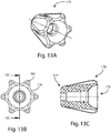
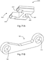
- FIGS. 13A-13C show one example of a rotation knob 175.
- the rotation knob 175 can have an outer surface that is larger in diameter at its proximal end 178 and smaller in diameter at its distal end 177.
- the outer surface of the rotation knob 175 can be sized and shaped to engage with a surgeon's finger or thumb to facilitate rotation of the rotation knob 175.
- the rotation knob 175 can have one or more ribs 181 and one or more depressions 176 formed in the outer surface of the rotation knob 175.
- the spacing of the ribs 181 and the size and depth of the depressions 176 are preferably sized to fit the width and shape of the average surgeon's fingers and/or thumb.
- the rotation knob 175 is preferably located close enough to the handle section 101 to allow the surgeon to rotate the rotation knob 175 with one hand.
- the surgeon may grasp the handle section 101 with one hand and use the thumb or index finger of the same hand to rotate the rotation knob 175.
- the rotation knob 175 may have an inner chamber 179 formed within the rotation knob 175 and shaped to receive a suitable pivot housing 141, as shown in FIG. 5 and FIGS. 8A-8C .
- a working shaft 182 may be engaged with the rotation knob 175 such that rotating the rotation knob 175 will rotate the working shaft 182 and orient an end effector (not shown) disposed at the distal end of the working shaft 182.
- the working shaft 182 may not be fixedly attached to the rotation knob 175.
- the rotation knob 175 may be fixedly attached to a working rod (not shown) which may run through the working shaft 182 with the working rod connected to the end effector.
- rotating the rotation knob 175 will rotate the working rod disposed within the working shaft 182 in order to rotate and orient the end effector.
- rotation of the end effector may be prevented, under certain circumstances, by means that are known in the art.
- any of the surgical instruments disclosed herein may also include ratcheting mechanisms to lock the end effector in one or more positions.
- actuating the ratcheting mechanism may lock the jaws or keep the jaws from opening wider.
- the ratcheting mechanism may provide discrete "locked” positions, or alternatively, the ratcheting mechanism may provide an infinite number of "locked” positions, as will be discussed in greater detail below.
- a retaining pin 180 may be inserted through an aperture formed in the side of the rotation knob 175.
- the retaining pin 180 may project, at least partially, into the inside of the inner chamber 179 of the rotation knob 175 and engage an annular groove 150 formed within the larger diameter portion 151 of the hollow shaft 142 of the pivot housing 141.
- the retaining pin 180 will not permit the rotation knob 175 to move translationally with respect to the longitudinal axis 183 of the working shaft 182, yet the retaining pin 180 will allow the rotation knob 175 to rotate freely about the longitudinal axis of the working shaft 182.
- FIG. 5 shows a restoring spring 173 that can be used in some examples of the present disclosure to keep the actuator 170 under constant tension.
- the actuator 170 may be threaded through the bore 161 of the connector 160 such that the distal connector 171 of the actuator 170 engages the chamfered surface 162 of the connector 160 when the actuator 170 is pulled in the proximal direction by the surgeon.
- the actuator 170 can be threaded through the restoring spring 173, the inner bore 155 of the pivot housing 141, the guide hole 169 of the pivot pin 164 disposed within the pivot pin hole 148 of the pivot housing 141, and through the actuator bore 133 of the second handle 122 such that the proximal connector 172 of the actuator 170 can be disposed within the actuator connection recess 125 of the second handle 122.
- the restoring spring 173 may be disposed within the inner bore 155 of the hollow shaft 142 of the pivot housing 141. The restoring spring 173 can exert a force on the proximal end of the connector 160 to move the connector 160 in the distal direction and keep the actuator 170 under constant tension.
- the second handle 122 has a natural or normal position to which it returns when the second handle 122 is at rest.
- a "sprung” second handle 122 may be useful when the instrument 100 is used in a "palm” grip style. In this configuration, the "sprung" handle provides a natural resistance to the surgeon's hand that allows the surgeon to retain the handle section 101 with the surgeon's palm independent of the finger loops.
- other embodiments can have second handles 122 that are "unsprung.” In this configuration, the second handle 122 may be at rest in any position when the second handle 122 is not acted upon by the surgeon.
- the pivot head portion 156 of the pivot housing 141 may be inserted into the pivot housing slot 117 of the first handle 102 such that the pivot pin hole 148 of the pivot housing 141 and the pivot pin hole 106 of the first handle 102 are in alignment.
- a pivot pin 164 may then be inserted through the pivot pin hole 106 of the first handle 102 and into the pivot pin hole 148 of the pivot housing 141.
- the guide hole 169 of the pivot pin 164 may be oriented such that the distal end 166 of the guide hole 169 faces toward the working shaft 182 and the proximal end 167 of the guide hole 169 faces the handle section 101. Stop pins 168 may also be inserted through the stop pin holes 103 of the first handle 102 and into the stop pin slots 152 of the pivot housing 141.
- the head portion 127 of the second handle 122 may be inserted into the second handle receiver slot 113 of the first handle 102 and secured to the first handle 102 by a pivot pin 135 inserted through the pin hole 107 of the first handle 102 and through the latch release cavity 123 of the second handle 122.
- the force of the spring detent 124 combined with the constant tension of the actuator 170 will keep the pivot pin 135 in the proximal end of the latch release cavity 123 when the second handle 122 is at rest (see FIG. 15 ).
- a locking member 158 can be inserted into the cavity 120 of the first handle 102 (see FIG.
- the proximal end of the locking member 158 may be attached to a surface of the head portion 127 of the second handle 122 disposed within the second handle receiver slot 113 of the first handle 102.
- the locking member 158 may be fixedly or rigidly engaged with the head portion 127, or a surface of the head portion 127, of the second handle 122. In other examples, there may be a mechanical junction between the second handle 120 and the locking member 158.
- the locking member 158 may be pivotably connected to the head portion 127 of the second handle 122.
- the locking member 158 may also be spring biased to aid the engagement or the disengagement of the locking teeth 159 of the locking member 158 with the locking teeth 145 of the pivot housing 141.
- the operation of the surgical instrument 100 will be explained in more detail along with the functional relationships between the various components of the surgical instrument 100.
- the restoring spring 173 pushes distally on the connector 160 to keep the actuator 170 under constant tension.
- the spring detent 124 biases the second handle pivot pin 135 toward the proximal and of the latch release cavity 123.
- the locking teeth 159 of the locking member 158 can be engaged with the locking teeth 145 of the pivot housing 141 such that the handle section 101 is not free to pivot with respect to the working shaft section 174.
- a practitioner may disengage the locking member 158 to allow the handle section to pivot, pivot the handle section to a desired angle position, and reengage the locking mechanism to prevent the handle section from pivoting.
- a surgeon may grasp the handle section 101 with his or her hand and squeeze the second handle 122 to move the second handle 122 closer to the first handle 102.
- the second handle will tend to pivot in a counterclockwise direction around the second handle pivot pin 135, pulling the actuator 170 toward the surgeon and engaging an end effector (not shown) connected to the distal connector 171 of the actuator 170. Pulling the actuator 170 in this fashion creates a tensile load down the actuator 170 which may be transferred to an inner shaft (not shown) connected to the distal connector 171 of the actuator 170 to operate the end effector.
- the relative locations of the second handle pivot 135 and an actuator connection recess 125 may be reversed such that compressing the handles together creates a compressive load down the working shaft and/or a linear motion away from the surgeon.
- a practitioner may control an end effector by moving the first and second handles relative to each other to cause the actuator 170 to affect the end effector.
- the size and shape of the guide hole 167 in the pivot pin 164, along with the size and shape of the proximal opening 146 of the pivot housing 141, can allow the actuator 170 to bend upward or downward as the handle section 101 pivots upward or downward.
- the actuator 170 defines an actuation path length between the second handle and the proximal end of an actuator target, such as a working rod (not shown), connected to an end effector (not shown).
- an actuator target such as a working rod (not shown)
- the actuation path length remains substantially constant because the actuator 170 is restrained to the centerline of the joint through the pivot pin 164.
- pivoting the handle section 101 in either direction will not substantially move or otherwise affect the end effector.
- the actuator 170 can be kept under constant tension by the restoring spring 173, independent of which ever pivot position the handle section 101 assumes.
- Examples of the present disclosure allow the second handle 122 to control whether or not the handle section 101 can pivot.
- the second handle 122 can be positioned in a first position to lock the pivot section 140 and prevent the handle section 101 from pivoting relative to the working shaft section 174.
- the second handle 122 can also be positioned in a second position to unlock the pivot section 140 and allow the handle section 122 to pivot relative to the working shaft section 174.
- the second handle 122 can control whether or not the handle section 101 can pivot utilizing a system including a pivot pin 135, a latch release cavity 123 formed within the second handle 122, a spring detent 124 and a locking member 158 engaged with the second handle 122.
- the second handle 122 may be pivotably engaged to the first handle 102 by the pivot pin 135 disposed within the latch release cavity 123 of the second handle 102 threaded through the pin holes 107 formed in the first handle 102.
- the second handle 122 At rest, the second handle 122 is in a first position with the spring detent 124 imposing a bias force upon the pivot pin 135 forcing the head portion 127 of the second handle 122 to move in the distal direction and the pivot pin 135 to move into the proximal end of the latch release cavity 123.
- the locking member 158 engaged with the second handle 122 may also move in the distal direction along with the head portion 127 of the second handle 122 to allow the pivot section 140 to lock.
- the surgeon can apply and maintain a counterclockwise force on the second handle 122 to force the second handle 122 into a second position that will allow the pivot section 140 to unlock and permit the handle section 101 to pivot.
- the biasing force of the spring detent 124 is overcome allowing the head portion 127 of the second handle 122 to move in the proximal direction forcing the pivot pin 135 into the distal end of the latch release cavity 123.
- the locking member 158 engaged with the second handle 122 may also move in the proximal direction with the head portion 127 of the second handle 122 to allow the pivot section 140 to unlock.
- the pivot housing 141 includes a first locking surface 157 and the locking member 158 includes a second locking surface 163.
- the first and second locking surfaces can be any size, shape, or texture.
- the first and second locking surfaces can made from any suitable materials that will allow the first and second locking surfaces to interact with each other to lock the pivot section 140.
- the first and second locking surfaces may be relatively smooth and made from frictional materials that allow the locking surfaces to frictionally engage with one another at any point and at any angle.
- the first and second locking surfaces may be smooth and made of rubber, or a rubber-like material, such that when the first and second locking surfaces are pressed together frictional forces keep the pivot section 140 locked.
- rubber or rubber-like material, includes any naturally occurring or synthetic material exhibiting frictional properties suitable to substantially lock the pivot section 140.
- the handle section can be selectively positioned and locked in an infinite number of angled positions relative to the longitudinal axis of the working shaft section over a range of angles defined by ⁇ max and ⁇ min .
- the handle section 101 can assume in a single plane.
- the handle section 101 can be angled in multiple planes with respect to the working shaft section 174.
- a pivot joint section 140 having a multi-axial or poly axial articulation can be utilized.
- the handle section 101 can be angled in multiple planes with respect to the working shaft section 174 utilizing a discrete number of different angle positions for one or more of the planes.
- the handle section 101 can be angled in multiple planes with respect to the working shaft section 174 utilizing an infinite number of different angle positions for one or more of the planes.
- a similarly functioning latch component may be utilized to lock the pivot joint section in each of its respective planes of movement.
- the handle section 101 can be selectively positioned in multiple discrete angled positions relative to the longitudinal axis 183 of the working shaft section 174 over a range of angles defined by an angle ⁇ max and an angle ⁇ min .
- the handle section 101 can be selectively positioned in three discrete angled positions relative to the longitudinal axis 183 of the working shaft section 174.
- the handle section 101 can be selectively positioned in 3 discrete angled positions corresponding to about 35°, 0°, and -35°.
- the first locking surface 157 of the pivot housing 141 and the second locking surface 163 of the locking member 158 may comprise one or more locking teeth 145, 159.
- the locking teeth 145, 159 may interact with each other to lock the pivot section 140.
- the locking teeth 159 of the locking member 158 may be disengaged from the locking teeth 145 of the pivot housing 141.
- a surgeon may disengage the locking teeth 159 of the locking member 158 from the locking teeth 145 of the pivot housing 141 by rotating the second handle 122 in a clockwise direction, about the second handle pivot pin 135.
- Rotating the second handle 122 in the clockwise direction with enough force will overcome the spring bias of the spring detent 124 and force the second handle 122 to move translationally with respect to the pivot pin 135 such that the distal end of the latch release cavity 123 moves proximally toward the pivot pin 135 to receive the pivot pin 135 into the distal end of the latch release cavity 123.
- the head portion 127 of the second handle 122 has moved proximally enough to disengage the locking member 158 from the pivot housing 141 allowing the handle section 101 to pivot.
- the surgeon may continue to apply a clockwise force to the second handle 122 to keep the locking member 158 disengaged while he or she rotates the handle section 101 to the new desired angular position.
- the surgeon may then stop applying the clockwise rotational force to the second handle 122 and allow the spring bias of the spring detent 124 to force the second handle 122 to move back in the distal direction and allow the proximal end of the latch release cavity 123 to receive the second handle pivot pin 135.
- the locking teeth 159 of the locking member 158 can engage the locking teeth 145 of the pivot housing 141, locking the handle section 101 in the desired angular position and preventing the handle section 101 from pivoting with respect to the working shaft section 17 4.
- the number of different angled positions the handle section 101 can assume can be dependent on the number, size, and shape of the locking teeth 145 of the pivot housing 141 and the locking teeth 159 of the locking member 158. For example, increasing the number of locking teeth 145 on the pivot housing 141 will result in a greater number of discrete angled positions that the handle section 101 can assume. However, increasing the number of locking teeth 145 on the pivot housing 141 may result in smaller locking teeth 145, 159 which may result in teeth that are not mechanically strong enough to the withstand forces applied to the teeth during normal operation of the surgical instrument 100.
- stop pins 168 disposed within the stop pin slots 152 of the pivot housing 141 can be used to limit how far the handle section 101 may pivot.
- the stop pins 168 will rotate counterclockwise in their respective stop pin slots 152, about the pivot pin 164. In this example, if the surgeon continues to rotate the handle section 101 in the counterclockwise position, eventually the stop pins will contact the ends of their respective stop pin slots 152 preventing further rotation in the counterclockwise direction.
- the pivot housing 141 may include a top angled surface 144 and a bottom angled surface 149 which may act as "hard stops" to interact with complementary surfaces of the first handle 102 or the second handle 122 to prevent further rotation in either the clockwise or the counterclockwise direction.
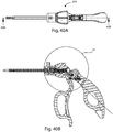
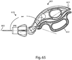
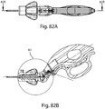
- FIGS. 16-43 a surgical instrument 200 in accordance with an embodiment of the present invention is illustrated.
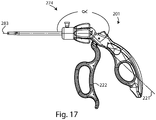
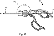
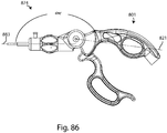
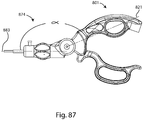
- FIG. 16 shows an isometric view of a surgical instrument 200 having a working shaft section 274 at its distal end, a handle section 201 at its proximal end, and a pivot section 240 intermediate the working shaft section 274 and the handle section 201.
- the handle section 201 may include a first handle 202 and a second handle 222.
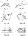
- FIG. 17 shows a side view of the surgical instrument 200 of FIG. 16 with the handle section 201 adjusted in a "drop-down" position relative to the longitudinal axis 283 of the working shaft section 274, similar to other embodiments disclosed herein.
- the surgical instrument of FIG. 16 also shows the second handle 22 in the "at rest” or biased position.
- FIG. 18 shows a side view of the surgical instrument 200 of FIG. 16 with the handle section 201 adjusted in a "drop-down” position relative to the longitudinal axis 283 of the working shaft section 274 and with the second handle 22 in the "forward" or unlocked position.
- FIG. 19 shows a side view of the surgical instrument 200 of FIG. 16 with the handle section 201 adjusted in an "in-line” position relative to the longitudinal axis 283 of the working shaft section 274.
- FIG. 20 shows a side view of the surgical instrument 200 of FIG. 16 with the handle section 201 adjusted in an "angled-up" position relative to the working shaft section 274.
- FIG. 21 shows an exploded view of the surgical instrument 200 with its various components.
- FIGS. 22A-37B illustrate the individual components of FIG. 21 in greater detail. A detailed description of the structure and features for each individual component will be given in a generally proximal to distal direction with reference to FIGS. 22A-37B . A detailed description of how each of the individual components interrelate with one another will then be given, along with the functional relationships between each component. Exemplary methods of using the surgical instrument 200 will also be given to illustrate how a surgeon can utilize the surgical instrument 200 to achieve greater ergonomic postures during surgery.
- FIGS. 22A-22C show various isometric views of a first handle 202, according to one embodiment of the present invention.
- the first handle 202 has a proximal end 296 and a distal end 297.
- the first handle 202 can have a top surface 205, a bottom surface 215, and two side surfaces 204.
- the top surface 205 can have a spatulate leaf shape and/or curve downward in the distal to proximal direction to better conform to the surgeon's palm.
- the top surface 105 can have a radius of curvature, or substantially lie along a radius of curvature.
- the radius of curvature can be between about 2 to 4 inches (5.08 to 10.16 cm).
- the radius of curvature can be between about 2.5 inches (6.35 cm) and 3.5 inches (8.89 cm).
- the radius of curvature is about 2.9 inches (7.37 cm).
- the top surface 205 of the first handle 202 may have a convex or rounded shape in the lateral direction between the two side surfaces 204 of the first handle 202.
- the top surface 205 is preferably shaped to be substantially wide enough between the two side surfaces 204 to provide adequate comfort to the surgeon's palm by providing sufficient surface contact area between the top surface 205 and the surgeon's palm to reduce or eliminate "hot spots" from forming on the surgeon's palm.
- the top surface 205 can have a maximum width and a minimum width in the lateral direction between the two side surfaces. In some embodiments, the minimum width of the top surface is located closer to the distal end of the first handle and the maximum width of the top surface is located closer to the proximal end of the first handle.
- the minimum width is between about 0.25 inches (0.64 cm) and about 0.75 inches (1.91 cm). In a particular embodiment, the minimum width is about 0.5 inches (1.27 cm). In some embodiments, the maximum width is between about 0.5 inches (1.27 cm) and about 1.25 inches (3.18 cm). In one embodiment, the maximum width is about 0.88 inches (2.24 cm).
- the location of the minimum width of the top surface can be chosen to correspond to the area of the top surface 205 that the surgeon's thumb traverses when the surgeon switches between a "finger loop" grip style and a "palm" grip style.
- Having the minimum width of the top surface in this area of the top surface 205 can allow the surgeon to more easily switch between the "finger loop” grip style and the "palm” grip style because the smaller width makes it easier for the surgeon's thumb to traverse this area of the handle.
- the top surface 205 may include a button slot 219 configured to receive a portion of a ratcheting mechanism, such as a button.
- the side surfaces 204 may include a thumb or finger rest area 208 formed on or into the side surfaces 204 to provide extra support for the surgeon's thumb when engaged along the side surface 204.
- the first handle 202 may have one or more finger loop holes 210 to receive one or more fingers during procedures requiring greater precision.
- the finger loop hole contact surface 209 may be convex in shape and wide enough to avoid or eliminate any "hot spots" from occurring on the surgeon's fingers during extended hours of operation.
- the first handle 202 can have a projection portion 211 at the proximal end 296 of the first handle 202.
- the projection portion 211 may provide greater surface area to interact with the surgeon's palm against the top surface 205.
- the projection portion 211 can include an electrical connector to receive external input.
- the first handle 202 can also have a bottom surface 215 and a bottom surface recess area 214 having a concave shape configured to interact with one or more of the surgeon's fingers as needed.
- any or all of the surfaces of the first handle 202 may include a comfort material (not shown) attached to one or more of the surfaces of the first handle 202, such as a soft rubber, polymer, or silicone.
- the comfort material may be applied to the first handle 202 after manufacture, or the comfort material may be integrally formed or molded to the first handle 202 during manufacture by any suitable manufacturing processes including, but not limited to, bonding or over-molding.
- the distal end 297 of the first handle 202 may include a head portion 212 for receiving a suitably shaped pivot housing 241 into the pivot housing slot 217.
- the head portion 212 may have stop pin holes 203 formed through both sides of the head portion 212 for receiving stop pins 268, as will be discussed in further detail below.
- the head portion 212 can have a pivot pin hole 206 formed through the head portion 212 configured to receive a pivot pin 264.
- the first handle 202 may include a pin hole 207 formed through, or substantially through, the side surfaces 204 of the first handle 202 and configured to receive a pivot pin 235 to pivotably secure a second handle 222.
- the surgical instrument 200 includes a dual pivot design with a first pivot connecting the handle section 201 to the working shaft section 274, and a second pivot connecting the second handle 222 to the first handle 202. Moreover, the first and second pivots are not coaxial with each other in this embodiment.
- the first handle 202 may include a receiver slot 213 configured and shaped to receive the head portion 227 of a suitable second handle 222, as will be discussed in further detail below.
- FIG. 6C illustrates a pivot housing slot 217 configured to receive a suitable pivot housing 241, in greater detail.
- FIG. 6C also illustrates an actuator aperture 218 formed within the first handle 202 proximal to the head portion 212 and shaped to allow an actuator 270 to be disposed therethrough.
- the first handle 202 may also have a ratchet slot 298 formed therein and configured to receive a suitable ratcheting mechanism, as will be discussed in greater detail below.
- the second handle 222 can have a proximal end 237 and a distal end 238.
- the second handle 222 can also have a top surface 226, a bottom surface 234, and two side surfaces 236. Each of the aforementioned surfaces may have a generally rounded or convex shape to increase comfort.
- the top surface 226 of the second handle 222 may have a slight "S-shaped" curvature formed therein moving in the distal to proximal direction.
- the distal end 238 of the second handle 222 may include a head portion 227 configured to interact with the receiver slot 213 of the first handle 202, as shown in FIGS. 22A-22C .
- the second handle 222 can have retainer members 286, a ramp pivot hole 284 and a ramp pivot slot, which will be discussed in greater detail below.
- the second handle 222 may have one or more finger loop holes 230 configured to receive one or more of the surgeon's fingers during procedures that require greater precision.
- the inner contact surface 229 of the finger loop hole 230 may have a rounded or convex shape to comfortably engage the fingers of the surgeon.
- the second handle 222 may have at least one finger contact surface. Moreover, the at least one finger contact surface can be configured to substantially lie along a radius of curvature.
- the radius of curvature can be between about 1.5 and 3.5 inches (3.8 and 8.9 cm) in some embodiments. In other embodiments, the radius of curvature may be between about 2 inches (5.1 cm) and 3 inches (7.6 cm). In a particular embodiment, the radius of curvature is about 2.5 inches (6.4 cm).
- the second handle 222 can have a finger loop 230 defining a first finger contact surface 239 configured to receive the surgeon's ring finger and middle finger, a projection 232 configured to receive the surgeon's pinky finger, and a recess portion 288 forming a third finger contact surface 228 configured to receive the surgeon's index finger.
- these finger contact surfaces can substantially lie along a radius of curvature.
- the first and second finger contact surfaces can substantially lie along a radius of curvature of about 2.5 inches (6.4 cm) and the third finger contact surface can be offset from the radius of the curvature of the first and second finger contact surfaces by about 0.0625 inches (0.159 cm).
- any or all of the surfaces of the second handle 222 may include a comfort/grip-enhancing material (not shown) attached to one or more of the surfaces of the second handle 222, such as a soft rubber, polymer, or silicone material.
- the comfort/grip-enhancing material may be applied to the second handle 222 after manufacture, or alternatively the comfort/grip-enhancing material may be integrally formed or molded to the second handle 222 during manufacture by several manufacturing processes, such as, bonding or over-molding.
- the head portion 227 of the second handle 222 can have a latch release cavity 223 formed through the head portion 227.
- the latch release cavity 223 may have an oblong or elongated oval shape configured to receive a pivot pin 235 to allow the pivot pin 235 to move translationally within the latch release cavity 223.
- the latch release cavity 223 can have a spring detent 224 just below the latch release cavity 223 to help control and bias the translational movement of the pivot pin 235, as will be discussed in greater detail below.
- the head portion 227 can have an actuator bore 233 formed through the head portion 227 and in communication with an actuator connection recess 225.
- FIG. 24 shows one embodiment of a multi-component second handle 222 having a removable top portion 287 which may be attached to the second handle 222 with pins 289 threaded through pin holes 290.
- the second handle 222 may comprise an alternative control member such as a trigger, a button, a lever, a truncated handle or any other structure suitable for a surgical instrument.
- the second handle 222 may be omitted entirely.
- FIGS. 25A-26C show one embodiment of a ratcheting mechanism 300 in accordance with one embodiment of the present invention.
- FIG. 25A shows an isometric view of an assembled ratcheting mechanism 300.
- FIG. 25B shows an exploded view of the ratcheting mechanism 300 of FIG. 25A .
- the ratcheting mechanism 300 may include a release member 301 pivotably connected to a ratchet body 310.
- the release member 301 may include a button 302 and a wedge release member 303 with the release member 301 configured to be pivotably connected to the ratchet body 310 using a suitable pivot pin 305 threaded through the pin holes 311 of the ratchet body 310 and through the pin hole 304 of the release member 301.
- the ratchet mechanism 300 can include a wedge member 306 biased toward one end of the ratcheting mechanism 300.
- the wedge member 306 can be disposed within the ratchet body 310 through the wedge member slots 312.
- Biasing members 307 can be disposed within the ratchet body 310 and held in place by guide members 308 threaded through the guide member slots 314.
- the biasing members 307 can be one or more springs which can impart a substantially constant bias force on the wedge member 306.
- the ratcheting mechanism 300 can also include a second ramp support pin 309.
- FIGS. 26A-26C show the ratchet body 310 in greater detail.
- the ratchet body 310 can have one or more first ramps 315 configured to interact with the wedge member 306 from above.
- FIG. 28 shows a second ramp 318 which may also interact with the wedge member 306 from below.
- the second ramp 318 can be pivotably mounted to the second handle 222 using the pivot pin hole 319 formed in the end of the second ramp 318 and a pivot pin 320 threaded through the pivot pin hole 319 of the second ramp 318 and through the pivot holes 284 formed in the second handle 222, as shown in FIG. 23B .
- the second ramp 318 may project outward from the ramp pivot slot 285 formed in the second handle 222.
- FIG. 41 shows a cross-sectional side view of the surgical instrument 200 with the ratcheting mechanism 300 installed in the surgical instrument 200.
- the ratcheting mechanism 300 can be attached to the first handle 202 with a pivot pin 305 and the second ramp support pin 309, as can be seen in FIG. 21 and FIG. 25B .
- FIG. 41 shows how the second ramp 318 can be pivotably attached to the second handle 222. The second ramp can project into the ratcheting mechanism 300 and between the second ramp support pin 309 and the wedge member 306.
- the second ramp 318 and the first ramp 315 can be angled with respect to each other such that the surfaces of the second ramp 318 and the first ramp 315 converge closer to each other moving in the distal direction and diverge away from each other moving in the proximal direction.
- a wedge member 306 disposed between the first ramp 315 and the second ramp 318 can be sized and shaped to interact with the first and second ramps as they angle toward each other in the distal direction and away from each other in the proximal direction.
- the width of the wedge member 306 can be less than the distance between the surfaces of the second ramp 318 and the first ramp 315 in the proximal direction and greater than the distance between the surfaces of the second ramp 318 in the first ramp 315 in the distal direction.
- first ramp 315 and a second ramp 318 two zones are formed between the first ramp 315 and a second ramp 318, a free zone in the proximal direction, and an interference zone in the distal direction.
- One or more biasing members 307 can also be used to impart a biasing force upon the wedge member 306, forcing the wedge member in the distal direction and into the interference zone.
- the one or more biasing members 307 can be one or more springs configured to impart a substantially constant force upon the wedge member 306.
- the second ramp 318 will become "pinched" between the wedge member and the second ramp support pin 309, preventing the second handle 222 from pivoting away from the first handle 202.
- the ratcheting mechanism 300 allows the first handle 202 and the second handle 222 to pivot towards each other, while preventing the first handle 202 and the second handle 222 from pivoting away from each other. In this manner, the ratcheting mechanism 300 allows for an infinite number of positional relationships to be selected and maintained between the first handle 202 and the second handle 222.
- the ratcheting mechanism 300 can be disabled, or released, with a suitable release member 301 that can force the wedge member 306 toward the free zone.
- the button 302 of the release member 301 can be depressed causing the wedge release member 303 to move in the proximal direction forcing the wedge member 306 into the free zone.
- the second ramp 318 is no longer "pinched" between the wedge member 306 and the second ramp support pin 309. The second ramp is now free to move in the distal direction, along with the second handle 222 which is attached to the second ramp 318.
- FIG. 27 shows a locking member 258 in accordance with one embodiment of the present invention.
- the locking member 258 may have a locking surface 263 including one or more locking teeth 259 formed in a surface of the locking member 258 and configured to engage the locking surface 257 of a suitable pivot housing 241, which can also include one or more teeth 245, and or one or more locking member receiver slots 299.
- the locking member 258 can also have projections 260 configured to interact with retainer members 286 formed on the head portion 227 of the second handle 222 to keep the locking member 258 engaged with the second handle 222.
- FIGS. 29A-29D show one embodiment of a connector 360 in accordance the present invention. and will be discussed in greater detail below.
- FIGS. 30A-30C show a pivot housing 241, in accordance with one embodiment of the present invention.
- the pivot housing 241 may include a hollow shaft 242 at its distal end and a pivot head portion 256 at its proximal end.
- the pivot head portion 256 may have a top surface 243, a bottom surface 254, side surfaces 247, a top angled surface 244, and a bottom angled surface 249.
- the top surface 243 and the bottom surface 254 may have partially spherical shapes configured to receive a suitable rotation knob 275 to allow the rotation knob 275 to rotate freely about the pivot head portion 256.
- the pivot head portion 256 may include a pivot pin hole 248 formed through the pivot head portion 256 between the sides 247.
- the pivot head portion 256 may include stop pin slots 252 formed through the pivot head portion 256 having elongated and curved oval shapes.
- the pivot head portion 256 may also include one or more locking teeth 245, and/or one or more locking member receiver slots 299, formed in a surface of the pivot head portion 256.
- the hollow shaft 242 may have a larger diameter portion 251 wherein the larger diameter portion 251 may include an annular groove 250 formed therein.
- the annular groove 250 may be shaped and configured to receive a retaining pin 280 to allow the rotation knob 275 to rotate freely about the pivot housing 241, while keeping the rotation knob 275 from moving translationally with respect to the working shaft 282.
- the hollow shaft 242 can have an inner bore 255 shaped to receive a suitable restoring spring 273.
- the inner bore 255 may be in communication with the pivot pin hole 248 and a proximal opening 246 in the pivot head portion 256.
- the proximal opening 246 may open wider moving in the distal to proximal direction with diverging top and bottom surfaces 253.
- FIG. 31A-31B show two isometric views of one embodiment of a working shaft section 274.
- FIG. 32 shows an exploded view of the working shaft section 274 of FIGS. 31A-31B .
- FIG. 33 shows one embodiment of a rotation knob 275 in accordance with the present disclosure.
- the rotation knob 275 can have an outer surface that is larger in diameter at its proximal end 278 and smaller in diameter at its distal end 277.
- the distal end 277 of the rotation knob 275 can form a translation guide 397 with one or more channels 384 formed in the translation guide 397.
- the rotation knob 275 can have an annular groove 380 formed in a surface of the translation guide 397 and configured to interact with a suitable retaining pin 385.
- the rotation knob 275 can also have one or more longitudinal apertures formed therein and configured to receive springs 382 and spheres 383 therein.
- the outer surface of the rotation knob 275 can be sized and shaped to engage with a surgeon's finger or thumb to facilitate rotation of the rotation knob 275.
- the rotation knob 275 can have one or more ribs 281 and one or more depressions 276 formed in the outer surface of the rotation knob 275.
- the spacing of the ribs 281 and the size and depth of the depressions 276 are preferably sized to fit the width and shape of the average surgeon's fingers and/or thumb.
- the size and shape of the depressions 276, as well as the number and spacing of the ribs 281 may be varied in any fashion or tailored in any way so as to fit any size finger or thumb.
- the rotation knob 275 is preferably located close enough to the handle section 201 to allow the surgeon to rotate the rotation knob 275 with one hand.
- the surgeon may grasp the handle section 201 with one hand and use the thumb or index finger of the same hand to rotate the rotation knob 275.
- FIG. 34 shows one embodiment of a control member 388 that can be used in the present disclosure.
- the control member can have a proximal end 389 and a distal end 390.
- the control member 388 can have a hollow body forming an inner surface with a smaller diameter portion 391 located toward the distal end 390 and a larger diameter portion (not shown) located toward the proximal end 389 of the control member 388.
- a chamfered surface 392 can be intermediate the smaller diameter portion 391 and the larger diameter portion.
- the control member 388 may have one or more translation members 394 engaged with a surface of the control member 388.
- FIG. 35 shows an isometric view of a working shaft collet 396 which can be used to frictionally engage a working shaft 282.
- FIGS. 36A-36B show isometric views of a hollow body 372 according to one embodiment of the present disclosure.
- the hollow body 372 can form an inner chamber and have one or more channels 373 formed in the surface of the inner chamber and configured to interact with the one or more translation members 394 of the control member 388.
- the proximal end 376 of the hollow body 372 can have a surface with one or more depressions 374 formed therein and configured to interact with spheres 383 inserted into the longitudinal apertures 381 of the rotation knob 275.
- the hollow body 372 may also have a port 375 connected to a surface of the hollow body 372.
- the port 375 can be in communication with the inner chamber of the hollow body 372.
- the port can be used as an aid in the cleaning process. For example, pressurized water can be forced into the port to help clean the inside of the hollow body 372.
- FIGS. 37A and 37B show isometric views of a working rod 350 that may be used with embodiments disclosed herein.
- the working rod 350 has a proximal end 351 and a distal end 352.
- the distal end 352 of the working rod 350 can be configured to attach a suitable end piece 358 for a given end effector (not shown).
- the proximal end 351 of the working rod 350 can have a connector portion 357 configured to interact with a suitable connector 360 as shown in FIGS. 29A-29D .
- the connector portion 357 can have a larger diameter portion 353, a smaller diameter portion 354, a first chamfered surface 355, and a second chamfered surface 356.
- the second chamfered surface 356 can be intermediate the smaller diameter portion 354 and the larger diameter portion 353.
- the first chamfered surface 355 can be proximal the larger diameter portion 353.
- the first chamfered surface 355 can be replaced with a partially spherical shaped end piece proximal the larger diameter portion 353.
- FIGS. 29A-29D illustrate one embodiment of a connector 360 which may be used with the surgical instruments disclosed herein.
- the connector 360 can have a proximal end 361 and a distal end 362.
- the proximal end of the connector 360 can have a chamber 365 configured to receive the distal end of a suitable actuator 270.
- the proximal end 361 of the connector 360 can also have a channel 367 configured to receive a portion of the distal end of the actuator 270.
- the channel 367 can have an offset shape to help thread and retain the distal end of the actuator 270 into the chamber 365.
- FIG. 29D shows a cross-sectional view of the connector 360, taken along the section line 29D-29D in FIG. 29C.
- FIG. 29D shows the inner chamber 366 formed in the connector 360 and configured to receive the proximal end 351 of a suitable working rod 350.
- FIG. 41 shows a cross-sectional side view of a surgical instrument 200 with a connector 360 disposed therein and engaged with a working rod 350 and the distal end of an actuator 270.
- a control member 388 at least partially encloses the connector 360.
- the smaller diameter portion 391 of the control member 388 is above the at least one retaining member 368 forcing the retaining member 368 to project into the smaller diameter portion 354 of the working rod 350 and locking the working rod 350 to the connector 360.
- the control member 388 may be moved in the distal direction such that the larger diameter portion 393 is above the at least one retaining member 368. With the control member 388 in this position, the working rod 350 can be pulled out of the inner chamber 366 of the connector 360 because the retaining member 368 can move up into the space formed by the larger diameter portion 393.
- FIG. 32-39B illustrate a system for translating the control member 388 between a first zone where the at least one retaining member is maintained in the locking position, and a second zone where the at least one retaining member can move to an unlocked position.
- the control member 388 can be disposed within the translation guide 397 with the translation members 394 of the control member threaded into the channels 384 of the translation guide 397.
- the translation members 394 can also be inserted into the channels 373 formed within the hollow body 372.
- FIG. 38B shows the translation members 394 of the control member 388 disposed within the channels 373 of the hollow body 372.
- Rotating the hollow body 372 clockwise with respect to the rotation knob 275 will translate the control member 388 in the distal direction, allowing the working rod 350 to be unlocked from the connector 360.
- Rotating the hollow body 372 counterclockwise with respect to the rotation knob 275 will translate the control member 388 in the proximal direction, locking the working rod 350 to the connector 360.
- the one or more channels 384 in the translation member 397 can have a pitch that allows for sufficient translation of the control member 388, in either direction, using a quarter turn rotation of the hollow body 372 with respect to the rotation knob 275.
- the spheres 383 and depressions 374 can interact with each other to produce tactile feedback to help the user know when the quarter turn of the hollow body 372 has been reached in either direction.
- a retaining pin (not shown) may be inserted through an aperture 379 formed in the side of the rotation knob 275, as seen in FIG. 33 .
- the retaining pin may project, at least partially, into the inside of the inner chamber of the rotation knob 275 and engage an annular groove 250 formed within the larger diameter portion 251 of the hollow shaft 242 of the pivot housing 241.
- the retaining pin will not permit the rotation knob 275 to move translationally with respect to the longitudinal axis 283 of the working shaft 282, yet the retaining pin will allow the rotation knob 275 to rotate freely about the longitudinal axis of the working shaft 282.
- FIGS. 44-59C a surgical instrument 400 in accordance with another embodiment of the present invention is illustrated.
- FIG. 44 shows an isometric view of a surgical instrument 400 having a working shaft section 474 at its distal end, a handle section 401 at its proximal end, and a pivot section 440 intermediate the working shaft section 474 and the handle section 401.
- the handle section 401 may include a first handle 402 and a second handle 422.
- FIG. 45 shows a side view of the surgical instrument 400 of FIG. 44 with the handle section 401 adjusted in a "drop-down" position relative to the longitudinal axis 483 of the working shaft section 474, similar to other embodiments disclosed herein.
- FIG. 46 shows a side view of the surgical instrument 400 of FIG. 44 with the handle section 401 adjusted in an "angled-up" position relative to the working shaft section 474.
- FIGS. 47-50B show various exploded views of the surgical instrument 400 for each subsection of the surgical instrument 400.
- FIGS. 51A-56C illustrate the individual components of FIGS. 47-50B in greater detail. A detailed description of the structure and features for each individual component will be given in a generally proximal to distal direction with reference to FIGS. 51A-56C . A detailed description of how each of the individual components interrelate with one another will then be given, along with the functional relationships between each component. Exemplary methods of using the surgical instrument 400 will also be given to illustrate how a surgeon can utilize the surgical instrument 400 to achieve greater ergonomic postures during surgery.
- FIGS. 51A-51C show various isometric views of a first handle 402, according to one embodiment of the present invention.
- the first handle 402 has a proximal end 496 and a distal end 497.
- the first handle 402 can have a top surface 405, a bottom surface 415, and two side surfaces 404.
- the top surface 405 can have a spatulate shape and/or curve downward in the distal to proximal direction to better conform to the surgeon's palm.
- the top surface 405 can have a radius of curvature, or substantially lie along a radius of curvature.
- the radius of curvature can be between about 2 and 4 inches (5.1 and 10.2 cm).
- the radius of curvature can be between about 2.5 inches (6.4 cm) and 3.5 inches (8.9 cm).
- the radius of curvature is about 2.9 inches (7.4 cm).
- the top surface 405 of the first handle 402 may have a convex or rounded shape in the lateral direction between the two side surfaces 404 of the first handle 402.
- the top surface 405 is preferably shaped to be substantially wide enough between the two side surfaces 404 to provide adequate comfort to the surgeon's palm by providing sufficient surface contact area between the top surface 405 and the surgeon's palm to reduce or eliminate "hot spots" from forming on the surgeon's palm.
- the top surface 405 can have a maximum width and a minimum width in the lateral direction between the two side surfaces. In some embodiments, the minimum width of the top surface is located closer to the distal end of the first handle and the maximum width of the top surface is located closer to the proximal end of the first handle.
- the minimum width is between about 0.25 inches (0.64 cm) and about 0.75 inches (1.91 cm). In a particular embodiment, the minimum width is about 0.5 inches (1.3 cm). In some embodiments, the maximum width is between about 0.5 inches (1.3 cm) and about 1.25 inches (3.18 cm). In one embodiment, the maximum width is about 0.88 inches (2.24 cm).
- the location of the minimum width of the top surface can be chosen to correspond to the area of the top surface 405 that the surgeon's thumb traverses when the surgeon switches between a "finger loop" grip style and a "palm” grip style.
- Having the minimum width of the top surface in this area of the top surface 405 can allow the surgeon to more easily switch between the "finger loop” grip style and the "palm” grip style because the smaller width makes it easier for the surgeon's thumb to traverse this area of the handle.
- the top surface 405 may include a button slot 419 configured to receive a portion of a ratcheting mechanism, such as a button.
- the side surfaces 404 may include a thumb or finger rest area 408 formed on or into the side surfaces 404 to provide extra support for the surgeon's thumb when engaged along the side surface 404.
- the first handle 402 may have one or more finger loop holes 410 to receive one or more fingers during procedures requiring greater precision.
- the finger loop hole contact surface 409 may be convex in shape and wide enough to avoid or eliminate any "hot spots" from occurring on the surgeon's fingers during extended hours of operation.
- the first handle 402 can have a projection portion 411 at the proximal end 496 of the first handle 402.
- the projection portion 411 may provide greater surface area to interact with the surgeon's palm against the top surface 405.
- the projection portion 411 can include an electrical connector to receive external input.
- the first handle 402 can also have a bottom surface recess area 414 having a concave shape configured to interact with one or more of the surgeon's fingers as needed.
- any or all of the surfaces of the first handle 402 may include a comfort material (not shown) attached to one or more of the surfaces of the first handle 402, such as a soft rubber, polymer, or silicone.
- the comfort material may be applied to the first handle 402 after manufacture, or the comfort material may be integrally formed or molded to the first handle 402 during manufacture by any suitable manufacturing processes including, but not limited to, bonding or over-molding.
- the distal end 497 of the first handle 402 may include a head portion 412 for receiving a suitably shaped pivot housing 441 into the pivot housing slot 417.
- the head portion 412 may have stop pin holes 403 formed through both sides of the head portion 412 for receiving stop pins 468, as will be discussed in further detail below.
- the head portion 412 can have a pivot pin hole 406 formed through the head portion 412 configured to receive a pivot pin 464.
- the first handle 402 may include a pin hole 407 formed through, or substantially through, the side surfaces 404 of the first handle 402 and configured to receive a pivot pin 435 to pivotably secure a second handle 422.
- the surgical instrument 400 includes a dual pivot design with a first pivot connecting the handle section 401 to the working shaft section 474, and a second pivot connecting the second handle 422 to the first handle 402. Moreover, the first and second pivots are not coaxial with each other in this embodiment.
- the first handle 402 may include a receiver slot 413 configured and shaped to receive the head portion 427 of a suitable second handle 422, as will be discussed in further detail below.
- FIG. 51C also illustrates the pivot housing slot 417 configured to receive a suitable pivot housing 441, in greater detail.
- FIG. SIC also illustrates an actuator aperture 418 formed within the first handle 402 proximal to the head portion 412 and shaped to allow an actuator 470 to be disposed therethrough.
- the first handle 402 may also have a ratchet slot 498 formed therein and configured to receive a suitable ratcheting mechanism, as will be discussed in greater detail below.
- the second handle 422 can have a proximal end 437 and a distal end 438.
- the second handle 422 can also have a top surface 426, a bottom surface 434, and two side surfaces 436. Each of the aforementioned surfaces may have a generally rounded or convex shape to increase comfort.
- the top surface 426 of the second handle 422 may have a slight "S-shaped" curvature formed therein moving in the distal to proximal direction.
- the distal end 438 of the second handle 422 may include a head portion 427 configured to interact with the receiver slot 413 of the first handle 402, as shown in FIGS. 51A-51C .
- the second handle 422 can have retainer members 486, a ramp pivot hole 484 and a ramp pivot slot (not shown), which will be discussed in greater detail below.
- the second handle 422 may have one or more finger loop holes 430 configured to receive one or more of the surgeon's fingers during procedures that require greater precision.
- the inner contact surface 429 of the finger loop hole 430 may have a rounded or convex shape to comfortably engage the fingers of the surgeon.
- the second handle 422 may have at least one finger contact surface. Moreover, the at least one finger contact surface can be configured to substantially lie along a radius of curvature.
- the radius of curvature can be between about 1.5 and 3.5 inches (3.8 and 8.9 cm) in some embodiments. In other embodiments, the radius of curvature may be between about 2 inches (5.1 cm) and 3 inches (7.6 cm). In a particular embodiment, the radius of curvature is about 2.5 inches (6.4 cm).
- the second handle 422 can have a finger loop 430 defining a first finger contact surface 439 configured to receive the surgeon's ring finger and middle finger, a projection 432 configured to receive the surgeon's pinky finger, and a recess portion 488 forming a third finger contact surface 428 configured to receive the surgeon's index finger.
- these finger contact surfaces can substantially lie along a radius of curvature.
- the first and second finger contact surfaces can substantially lie along a radius of curvature of about 2.5 inches (6.4 cm) and the third finger contact surface can be offset from the radius of the curvature of the first and second finger contact surfaces by about 0.0625 inches (0.159 cm).
- any or all of the surfaces of the second handle 422 may include a comfort/grip-enhancing material (not shown) attached to one or more of the surfaces of the second handle 422, such as a soft rubber, polymer, or silicone material.
- the comfort/grip-enhancing material may be applied to the second handle 422 after manufacture, or alternatively the comfort/grip-enhancing material may be integrally formed or molded to the second handle 422 during manufacture by several manufacturing processes, such as, bonding or over-molding.
- the head portion 427 of the second handle 422 can have a latch release cavity 423 formed through the head portion 427.
- the latch release cavity 423 may have an oblong or elongated oval shape configured to receive a pivot pin 435 to allow the pivot pin 435 to move translationally within the latch release cavity 423.
- the latch release cavity 423 can have a spring detent 424 just below the latch release cavity 423 to help control and bias the translational movement of the pivot pin 435, as will be discussed in greater detail below.
- the head portion 427 can have an actuator bore 433 formed through the head portion 427 and in communication with an actuator connection recess 425.
- FIG. 47 shows one embodiment of a multi-component second handle 422 having a removable top portion 487 which may be attached to the second handle 422 with one or more pins 489 threaded through pin holes 490.
- the second handle 422 may comprise an alternative control member such as a trigger, a button, a lever, a truncated handle or any other structure suitable for a surgical instrument.
- the second handle 422 may be omitted entirely.
- FIGS. 53A-53B show a pivot housing 441, in accordance with one embodiment of the present invention.
- the pivot housing 441 may include a hollow shaft 442 pivot head portion 456.
- the pivot head portion 456 may have a top angled surface 444 and a bottom angled surface 449.
- the pivot head portion 456 may include a pivot pin hole 448 formed through the pivot head portion 456.
- the pivot head portion 456 may include stop pin slots 452 formed through the pivot head portion 456 having elongated and curved oval shapes.
- the pivot head portion 456 may also include one or more locking teeth 445, and/or one or more locking member receiver slots 499, formed in a surface of the pivot head portion 456.
- the pivot housing 441 can also have a pin hole 570 configured to receive a pivot pin 559 to pivotably connect a suitable connector 560 within the pivot housing 441.
- the pivot housing 441 can also have an input port 530 to receive external input, such as electricity or a fluid.
- FIG. 54A shows a locking member 458 in accordance with one embodiment of the present invention.
- the locking member 458 may have one or more locking surfaces 463 including one or more locking teeth 459 formed in a surface of the locking member 458 and configured to engage the locking surface 457 of a suitable pivot housing 441, which can also include one or more teeth 445, and or one or more locking member receiver slots 499.
- the locking member 458 can also have projections 460 configured to interact with retainer members 486 formed on the head portion 427 of the second handle 422 to keep the locking member 458 engaged with the second handle 422.
- FIG. 54B shows an isometric view of a pivot pin 464 according to another embodiment of the present invention.
- the pivot pin 464 may have a guide hole 469 formed through the center of the pivot pin 464 between one or more connecting members 465.
- the guide hole 469 can restrain an actuator 470 along the centerline of the joint as the handle section 401 pivots relative to the working shaft section 482.
- FIG. 55A illustrates one embodiment of the connector 560 which may be used with the surgical instruments disclosed herein.
- the connector 560 can have a proximal end 561 and a distal end 562.
- the proximal end 561 of the connector 560 can have a pin hole 546 configured to receive a suitable pivot pin (not shown) threaded through the distal end of a suitable actuator 470 to pivotably connect the actuator 470 to the connector 560.
- the distal end 562 of the connector 560 can have a connection aperture 548 in communication with a longitudinal aperture 563 configured to receive the proximal end 551 of a suitable working rod 550.
- FIG. 55B shows a portion of a ratcheting mechanism 500, similar to other ratcheting mechanisms discussed herein, which can be used in with surgical instruments disclosed herein.
- FIGS. 56A-56E show a rotation knob 475 in accordance with another embodiment of the present disclosure.
- the rotation knob 475 can have one or more ribs 481 and one or more depressions 476 formed in the outer surface of the rotation knob 475.
- the rotation knob 475 can also have one or more longitudinal apertures 581 configured to receive springs 582 and spheres 583 therein.
- the rotation knob 475 may also have a port 575 connected to a surface of the rotation knob 475.
- the port 575 can be in communication with the inner chamber of the rotation knob 475 and can be used as an aid in the cleaning process. For example, pressurized water can be forced into the port 575 to help clean the inside of the rotation knob 475.
- the rotation knob 475 can be held in place with a suitable retaining pin 480 disposed within aperture 579, similar to other embodiments disclosed herein.
- the actuator 470 is pivotably connected to the connector 560 with a suitable pivot pin threaded through pin hole 546. Rotating the second handle 422 toward the first handle 402 will pull the actuator 470 in the proximal direction causing the connector 560 to pivot toward the proximal direction pulling the working rod 550 in the proximal direction.
- the working rod 550 can move translationally within the longitudinal aperture 563 of the connector 560 as the connector pivots back and forth.
- the working rod can also be moved in the distal direction by rotating the second handle 422 away from the first handle 402.
- the connector 560 can also have an aperture 548 configured to receive the proximal end of a working rod 550 and allow the working rod 550 to be coupled and decoupled from the connector 560.
- FIGS. 60-83 a surgical instrument 600 in accordance with another embodiment of the present invention is illustrated.
- FIG. 60 shows an isometric view of a surgical instrument 600 having a working shaft section 674 at its distal end, a handle section 601 at its proximal end, and a pivot section 640 intermediate the working shaft section 674 and the handle section 601.
- the handle section 601 may include a first handle 602 and a second handle 622.
- FIGS. 61-65 show side views of the surgical instrument 600 of FIG. 60 with the handle section 601 and the second handle 622 adjusted in various positions relative to the longitudinal axis 683 of the working shaft section 674, similar to other embodiments disclosed herein.
- FIG. 66 shows an exploded view of the surgical instrument 600.
- FIGS. 67A-73E illustrate the individual components of FIG. 66 in greater detail. A detailed description of the structure and features for each individual component will be given in a generally proximal to distal direction with reference to FIGS. 67A-73E . A detailed description of how each of the individual components interrelate with one another will then be given, along with the functional relationships between each component. Exemplary methods of using the surgical instrument 600 will also be given to illustrate how a surgeon can utilize the surgical instrument 600 to achieve greater ergonomic postures during surgery.
- FIGS. 67A-67C show various isometric views of a first handle 602, according to one embodiment of the present invention.
- the first handle 602 has a proximal end 696 and a distal end 697.
- the first handle 602 can have a top surface 605, a bottom surface 615, and two side surfaces 604.
- the top surface 605 can have a spatulate shape and/or curve downward in the distal to proximal direction to better conform to the surgeon's palm.
- the top surface 605 can have a radius of curvature, or substantially lie along a radius of curvature.
- the radius of curvature can be between about 2 and 4 inches (5.1 and 10.2 cm).
- the radius of curvature can be between about 2.5 inches (6.4 cm) and 3.5 inches (8.9 cm).
- the radius of curvature is about 2.9 inches (7.4 cm).
- the top surface 605 of the first handle 602 may have a convex or rounded shape in the lateral direction between the two side surfaces 604 of the first handle 602.
- the top surface 605 is preferably shaped to be substantially wide enough between the two side surfaces 604 to provide adequate comfort to the surgeon's palm by providing sufficient surface contact area between the top surface 605 and the surgeon's palm to reduce or eliminate "hot spots" from forming on the surgeon's palm.
- the top surface 605 can have a maximum width and a minimum width in the lateral direction between the two side surfaces. In some embodiments, the minimum width of the top surface is located closer to the distal end of the first handle and the maximum width of the top surface is located closer to the proximal end of the first handle.
- the minimum width is between about 0.25 inches (0.64 cm) and about 0.75 inches (1.91 cm). In a particular embodiment, the minimum width is about 0.5 inches (1.3 cm). In some embodiments, the maximum width is between about 0.5 inches (1.3 cm) and about 1.25 inches (3.18 cm). In one embodiment, the maximum width is about 0.88 inches (2.24 cm).
- the location of the minimum width of the top surface can be chosen to correspond to the area of the top surface 605 that the surgeon's thumb traverses when the surgeon switches between a "finger loop" grip style and a "palm” grip style.
- Having the minimum width of the top surface in this area of the top surface 605 can allow the surgeon to more easily switch between the "finger loop” grip style and the "palm” grip style because the smaller width makes it easier for the surgeon's thumb to traverse this area of the handle.
- the top surface 605 may include a button slot 619 configured to receive a portion of a ratcheting mechanism, such as a button.
- the side surfaces 604 may include a thumb or finger rest area 608 formed on or into the side surfaces 604 to provide extra support for the surgeon's thumb when engaged along the side surface 604.
- the first handle 602 may have one or more finger loop holes 610 to receive one or more fingers during procedures requiring greater precision.
- the finger loop hole contact surface 609 may be convex in shape and wide enough to avoid or eliminate any "hot spots" from occurring on the surgeon's fingers during extended hours of operation.
- the first handle 602 can have a projection portion 611 at the proximal end 696 of the first handle 602.
- the projection portion 611 may provide greater surface area to interact with the surgeon's palm against the top surface 605.
- the projection portion 611 can include an electrical connector to receive external input.
- any or all of the surfaces of the first handle 602 may include a comfort material (not shown) attached to one or more of the surfaces of the first handle 602, such as a soft rubber, polymer, or silicone.
- the comfort material may be applied to the first handle 602 after manufacture, or the comfort material may be integrally formed or molded to the first handle 602 during manufacture by any suitable manufacturing processes including, but not limited to, bonding or over-molding.
- the distal end 697 of the first handle 602 may include a head portion 612 for receiving a suitably shaped pivot housing 641 into the pivot housing slot 617.
- the head portion 612 may have stop pin holes 603 formed through both sides of the head portion 612 for receiving stop pins 668, as will be discussed in further detail below.
- the head portion 612 can have a pivot pin hole 606 formed through the head portion 612 configured to receive one or more pivot pins 664.
- the first handle 602 may include a pin hole 607 formed through, or substantially through, the side surfaces 604 of the first handle 602 and configured to receive a pivot pin 635 to pivotably secure a second handle 622.
- the surgical instrument 600 includes a dual pivot design with a first pivot connecting the handle section 601 to the working shaft section 674, and a second pivot connecting the second handle 622 to the first handle 602. Moreover, the first and second pivots are not coaxial with each other in this embodiment.
- the first handle 602 may include a receiver slot 613 configured and shaped to receive the head portion 627 of a suitable second handle 622.
- FIG. 67C also illustrates the pivot housing slot 617 configured to receive a suitable pivot housing 641, in greater detail.
- FIG. 67C also illustrates an actuator aperture 618 formed within the first handle 602 proximal to the head portion 612 and shaped to allow an actuator 670 to be disposed therethrough.
- the first handle 602 may also have a ratchet slot 698 formed therein and configured to receive a suitable ratcheting mechanism.
- the second handle portion 687 can have a proximal end 637 and a distal end 638.
- the second handle portion 687 may include a head portion 627 configured to interact with the receiver slot 613 of the first handle 602, as shown in FIGS. 67B-67C .
- the head portion 627 of the second handle 622 can have a latch release cavity 623 formed through the head portion 627.
- the latch release cavity 623 may have an oblong or elongated oval shape configured to receive a pivot pin 635 to allow the pivot pin 635 to move translationally within the latch release cavity 623.
- the latch release cavity 623 can have a spring detent 624 just below the latch release cavity 623 to help control and bias the translational movement of the pivot pin 635, discussed previously.
- the head portion 627 can have a slot 633 formed therein and configured to receive a suitable rigid member 742, as shown in FIG. 71B .
- the rigid member 742 can be pivotably attached to the second handle portion 687 with a pivot pin 740 threaded through the pin hole 744.
- FIGS. 69A-70B show a pivot housing 641, in accordance with one embodiment of the present invention.
- the pivot housing 641 may include a hollow shaft 642 at its distal end and a pivot head portion 656 at its proximal end.
- the pivot head portion 656 may have a top surface 643, a bottom surface 654, side surfaces 647, a top angled surface 644, and a bottom angled surface 649.
- the top surface 643 and the bottom surface 654 may have partially spherical shapes configured to receive a suitable rotation knob 675 to allow the rotation knob 675 to rotate freely about the pivot head portion 656.
- the pivot head portion 656 may include one or more pivot pin holes 648 formed through the pivot head portion 656 between the sides 647.
- the pivot head portion 656 may include stop pin slots 652 formed through the pivot head portion 656 having elongated and curved oval shapes.
- the pivot head portion 656 may also include one or more locking teeth 645, and/or one or more locking member receiver slots 699, formed in a surface of the pivot head portion 656.
- the hollow shaft 642 may have an annular groove 650 formed therein.
- the annular groove 650 may be shaped and configured to receive a retaining pin (not shown) to allow the rotation knob 675 to rotate freely about the pivot housing 641, while keeping the rotation knob 675 from moving translationally with respect to the working shaft 682.
- the hollow shaft 642 can have an inner bore 655 in communication with the one or more pivot pin holes 648 and a proximal opening 646 in the pivot head portion 656.
- the pivot housing 641 can also have a pin hole 770 to pivotably connect a suitable connector 760 within the pivot housing 641.
- FIG. 71A shows a locking member 658 in accordance with one embodiment of the present invention.
- the locking member 658 may have one or more locking surfaces 663 including one or more locking teeth 659 formed in a surface of the locking member 658 and configured to engage the locking surface 657 of a suitable pivot housing 641, which can also include one or more teeth 645, and or one or more locking member receiver slots 699.
- the locking member 658 can also have projections 660 configured to interact with retainer members 686 formed on the head portion 627 of the second handle 622 to keep the locking member 658 engaged with the second handle 622.
- FIG. 71B shows a portion of an actuator 670 according to another embodiment of the present invention.
- the rigid member 742 can have pin holes 744, 745 configured to receive suitable pivot pins 740, 741 such that the rigid member 742 can be pivotably connected to the second handle 622 and the connector 760, as can be seen in FIGS. 74A-83 .
- FIGS. 72A-72B illustrate another embodiment of a connector 760 which may be used with the surgical instruments disclosed herein.
- the connector 760 can have a proximal end 761 and a distal end 762.
- the proximal end 761 of the connector 760 can have a pin hole 746 configured to receive a suitable pivot pin threaded through the pin hole 745 of the rigid member 742.
- the distal end 762 of the connector 760 can have a connection aperture 764 in communication with a longitudinal aperture 763 configured to receive the proximal end 751 of a suitable working rod 750.
- FIGS. 73A-73E show a rotation knob 675 in accordance with another embodiment of the present disclosure.
- the rotation knob 675 can have one or more ribs 681 and one or more depressions 676 formed in the outer surface of the rotation knob 675.
- the rotation knob 675 can also have one or more longitudinal apertures 781 configured to receive springs 782 and spheres 783 therein.
- the rotation knob 675 may also have a port 775 connected to a surface of the rotation knob 675.
- the port 775 can be in communication with the inner chamber 679 of the rotation knob 675 and can be used as an aid in the cleaning process. For example, pressurized water can be forced into the port 675 to help clean the inside of the rotation knob 675.
- the rotation knob 675 can be held in place with a suitable retaining pin (not shown) disposed within aperture 679, similar to other embodiments disclosed herein.
- the actuator 670 can be used to push or pull the working rod 750.
- the rigid member 742 can be pivotably engaged with the second handle 622 and pivotably engaged with the connector 760.
- the connector 760 can also be pivotably engaged with the pivot housing 641 about a pivot pin 759.
- the rigid member 742 is pulled in the proximal direction causing the connector 760 to pivot in the proximal direction, pulling the working rod 750 in the proximal direction.
- rotating the second handle 622 away from the first handle 602 pushes the rigid member 742 in the distal direction causing the connector 760 to pivot in the distal direction, pushing the working rod 750 in the distal direction.
- the distance between the pivot pins 635 and 740, as well as the distance between the pivot pin 635 and the center of force applied to the second handle 622, can be chosen to obtain a desired mechanical advantage applied to the rigid member 742.
- the distance between the pivot pins 635 and 740 can be chosen to be about 0.25 inches (0.64 cm) and the distance between the pivot pin 635 and the center of force applied to the second handle 622 can be chosen to be about 2.5 inches (6.4 cm).
- the ratio of these distances (2.5 inches/0.25 inches)(6.4 cm/0.64 cm) would result in the mechanical advantage of about 10.
- other distances and ratios can be chosen to obtain other mechanical advantages.
- the location of the pivot pin 741 can be chosen to be substantially coaxial with the pivot pins 664 which control the articulation of the handle section 601 in relation to the working shaft section 674.
- the axis of the pivot pin 741 is substantially coaxial with the axis of the pivot pins 664 when the second handle 622 is in the "at rest” position. If the second handle 622 is maintained in the "at rest” position as the handle section 601 is articulated, then the axes of the pivot pins 741 and 664 will substantially stay aligned with each other as the handle section 601 is articulated in the working rod 750 will not substantially move as the handle section 601 is articulated.
- the location of the pivot pin 741 relative to the pivot pins 664 can be chosen such that they are not substantially coaxial with each other. In these embodiments, articulating the handle section 601 can cause the working rod 750 to move, affecting the end effector. In these embodiments, the location of the pivot pin 741 relative to the pivot pins 664 is preferably chosen to minimize movement of the end effector as the handle section 601 is articulated. Accordingly, the movement of the end effector may be small and virtually imperceptible to the surgeon.
- FIGS. 84-97 a surgical instrument 800 is illustrated.
- FIG. 84 shows an isometric view of a surgical instrument 800 having a working shaft section 874 at its distal end, a handle section 801 at its proximal end, and a pivot section 840 intermediate the working shaft section 874 and the handle section 801.
- the handle section 801 may include a first handle 802 and a second handle 822.
- FIG. 85 shows a side view of the surgical instrument 800 of FIG. 84 with the handle section 801 adjusted in a "dropdown" position relative to the longitudinal axis 883 of the working shaft section 874, similar to other examples disclosed herein.
- FIG. 86 shows a side view of the surgical instrument 800 of FIG.
- FIG. 87 shows a side view of the surgical instrument 800 of FIG. 84 with the handle section 801 adjusted in an "angled-up" position relative to the working shaft section 874.
- FIG. 88 shows an exploded view of the surgical instrument 800.
- FIGS. 91A-95C illustrate the individual components of FIG. 88 in greater detail. A detailed description of the structure and features for each individual component will be given in a generally proximal to distal direction with reference to FIGS. 91A-95C . A detailed description of how each of the individual components interrelate with one another will then be given, along with the functional relationships between each component. Exemplary methods of using the surgical instrument 800 will also be given to illustrate how a surgeon can utilize the surgical instrument 800 to achieve greater ergonomic postures during surgery.
- FIGS. 91A- 91C show various isometric views of the first handle 802.
- the first handle 802 has a proximal end 896 and a distal end 897.
- the first handle 802 can have a top surface 805, a bottom surface 815, and two side surfaces 804.
- the top surface 805 can have a spatulate shape and/or curve downward in the distal to proximal direction to better conform to the surgeon's palm.
- the top surface 805 can have a radius of curvature, or substantially lie along a radius of curvature.
- the radius of curvature can be between about 2 and 4 inches (5.1 and 10.2 cm).
- the radius of curvature can be between about 2.5 inches (6.4 cm) and 3.5 inches (8.9 cm).
- the radius of curvature is about 2.9 inches (7.4 cm).
- the top surface 805 of the first handle 802 may have a convex or rounded shape in the lateral direction between the two side surfaces 804 of the first handle 802.
- the top surface 805 is preferably shaped to be substantially wide enough between the two side surfaces 804 to provide adequate comfort to the surgeon's palm by providing sufficient surface contact area between the top surface 805 and the surgeon's palm to reduce or eliminate "hot spots" from forming on the surgeon's palm.
- the top surface 805 can have a maximum width and a minimum width in the lateral direction between the two side surfaces. In some embodiments, the minimum width of the top surface is located closer to the distal end of the first handle and the maximum width of the top surface is located closer to the proximal end of the first handle.
- the minimum width is between about 0.25 inches (0.64 cm) and about 0.75 inches (1.91 cm). In a particular embodiment, the minimum width is about 0.5 inches (1.3 cm). In some embodiments, the maximum width is between about 0.5 inches (1.3 cm) and about 1.25 inches (3.18 cm). In one embodiment, the maximum width is about 0.88 inches (2.24 cm).
- the location of the minimum width of the top surface can be chosen to correspond to the area of the top surface 805 that the surgeon's thumb traverses when the surgeon switches between a "finger loop" grip style and a "palm” grip style.
- the side surfaces 804 may include a thumb or finger rest area 808 formed on or into the side surfaces 804 to provide extra support for the surgeon's thumb when engaged along the side surface 804.
- the first handle 802 may have one or more finger loop holes 810 to receive one or more fingers during procedures requiring greater precision.
- the finger loop hole contact surface 809 may be convex in shape and wide enough to avoid or eliminate any "hot spots" from occurring on the surgeon's fingers during extended hours of operation.
- the first handle 802 can have a projection portion 811 at the proximal end 896 of the first handle 802.
- the projection portion 811 may provide greater surface area to interact with the surgeon's palm against the top surface 805.
- the projection portion 811 can include an electrical connector to receive external input.
- any or all of the surfaces of the first handle 802 may include a comfort material (not shown) attached to one or more of the surfaces of the first handle 802, such as a soft rubber, polymer, or silicone.
- the comfort material may be applied to the first handle 802 after manufacture, or the comfort material may be integrally formed or molded to the first handle 802 during manufacture by any suitable manufacturing processes including, but not limited to, bonding or over-molding.
- the distal end 897 of the first handle 802 may include a head portion 812 for receiving a suitably shaped second handle 822 and connector 960 within the opening 925, as will be discussed in more detail below.
- the head portion 812 can also have lock members 922 configured to interact with complementary shaped lock receivers 923 formed in the pivot housing 841.
- the first handle 802 can also have a stop pin slot 852 to limit the articulation of a second handle 822 pivotably connected to the first handle 802.
- FIGS. 92A- 92C show a second handle 822.
- the second handle 822 can have a top surface 826, a finger loop hole 830, an inner contact surface 829, a projection 832 defining a contact surface 831 and a recess portion 828.
- the second handle 822 can also have a stop pin hole 803, a pivot pin hole 848, lock members 922, and a working rod slot 926.
- FIGS. 93A- 93D show a pivot housing 841.
- the pivot housing 841 can have lock receivers 923 formed in one or more sides and configured to interact with lock members 922 formed in the head portion 812 of the first handle 802.
- the pivot housing 841 can also have an annular groove 850 configured to receive a retaining pin (not shown) to engage a rotation knob 875.
- FIGS. 94A-94B show isometric views of a connector 960.
- the connector 960 can have lock receivers 923 formed therein, a pivot pin hole 848, a tab 927, and a working rod connector portion 961.
- FIGS. 95A- 95C show various views of a rotation knob 875.
- the rotation knob 875 can have ribs 881 and depressions 879 formed therein.
- the rotation knob 875 can also have a port 975 to aid in cleaning, as discussed previously.
- the rotation knob and 75 can also have an aperture 979 configured to receive a retaining pin (not shown) to engage the retaining knob 875 to the pivot housing 841.
- the rotation knob and 75 can also have an inner chamber 879 configured to receive a suitable working rod 950.
- FIGS. 96A-97 The operation of the surgical instrument 800 will now be given with reference to FIGS. 96A-97 .
- the working rod connector portion 961 rotates in the proximal direction pulling the working rod 950 in the proximal direction.
- the working rod connector portion 961 rotates in the distal direction pushing the working rod 950 in the distal direction.
- the biasing spring 998 is disposed between an inner surface of the pivot housing 841 and the first handle 802.
- the biasing spring 998 pushes the first handle 802 toward one side of the pivot housing 841 causing the lock members 922 of the second handle 822 to mate with the lock receivers 923 formed in the connector 960 and the lock members 922 of the first handle 802 to mate with the lock receivers 923 formed in the pivot housing 841.
- the pivot section 840 is locked in this position.
- the pivot section 840 can be unlocked by grabbing the handle section 801 and applying a counterforce against the biasing spring 998 to disengage the lock members 922 from the lock receivers 923.
- the pivot section 840 can then be articulated by maintaining this counterforce and rotating the handle section 801 to the desired location. Once the desired location is obtained, the pivot section 840 can be re-locked by discontinuing the counterforce against the biasing spring 998, causing the handle section 801 to move translationally such that lock members 922 can engage their respective lock receivers 923.
- pivoting means may be element 140 as shown in FIG. 1 , or element 240 as shown in FIG. 16 , or element 440 as shown in FIG. 44 , or element 640 as shown in FIG. 60 , or element 840 as shown in FIG. 84 .
- the locking means may be elements 157 and 163 in FIGS. 8C and 9 , or elements 263 and 257 in FIGS. 27 and 30B , or elements 463 and 457 in FIGS. 53B and 54A , or elements 663 and 657 in FIGS. 70A and 71A , or elements 923 and 922 in FIGS. 89B , 90B , 91C , 92B , 93A , and 94A .
- the second handle pivoting means may be element 135 in FIG. 5 , or element 235 in FIG. 21 , or element 435 in FIG. 47 , or element 635 in FIG. 66 , or element 864 in FIG. 88 .
- actuating means for affecting the end effector.
- the actuating means may be element 170 in FIG. 5 , or element 270 in FIG. 21 , or elements 470 and 560 in FIG. 47 , or elements 742 and 760 in FIG. 66 , or element 961 in FIG. 94B .
- Coupled is defined as connected, although not necessarily directly, and not necessarily mechanically.
- a step of an exemplary method or an element of a device that "comprises,” “has,” “includes” or “contains” one or more features, possesses those one or more features, but is not limited to possessing only those one or more features.
- a device or structure that is configured in a certain way is configured in at least that way, but may also be configured in ways that are not listed.
Description
- This disclosure relates to adjustable surgical instrument handles by which improved ergonomic positions can be obtained. Specifically, this disclosure relates to surgical instruments with pivoting handle sections for improved ergonomics.
- The present disclosure relates to instruments with adjustable handles. While the present disclosure is made in the context of laparoscopic instruments for the purposes of illustrating the concepts of the design, it is contemplated that the present design and/or variations thereof may be suited to other types of surgical instruments, such as arthroscopic, endoscopic, orthopedic, neurologic, cardiologic, suture passing, stapling, or minimally invasive instruments, among others. Furthermore, the principles embodied in the present disclosure may be applicable outside the fields of surgery or medical devices.
- Laparoscopy is an established field of surgery, but opportunities remain for improvement to the instruments. Existing laparoscopic instruments may present significant challenges to a surgeon. For example, the design of laparoscopic instruments may force a surgeon to place his hands, arms, and/or body in non-ergonomic, uncomfortable, and sometimes physically harmful positions. Articulated instrument tips have been introduced. In at least some of these designs, the handle position and/or orientation may be altered in order to reposition and/or reorient the end effector. However, the handle position and/or orientation tends to be dependent on, or tied to, the end effector position and/or orientation.
- There is a need for instrument designs that improve the ergonomics of the instruments in the user's hands. There is a need for instrument designs in which the handle position and/or orientation is independent of the end effector position and/or orientation. There is a need for instrument designs in which the user may adjust the instrument to keep the hands, arms, and/or body in an ergonomically appropriate or physiologically neutral position while positioning and/or orienting the end effector, or a working shaft of the instrument, to perform a procedure. There is also a need for instruments that reduce or eliminate the need to switch between different handle styles in the course of a procedure.
-
US 2007/0299469 discloses a laproscopic surgical device that includes a ratchet mechanism. The handle of the device is configured to manipulate a distal tool end of a laproscopic device. -
US 6,077,286 discloses an instrument having a shaft and a distal engaging element operated via a proximal actuator element integrated into a handle. The angle between the axis of the handle and the axis of the shaft can be varied and the handle is connected to the shaft via a universal joint. -
US 2001/027312 discloses an instrument with a handle which is able to undertake different positions during an operative procedure, thereby allowing comfortable or convenient positioning of the handle for the operative procedure being carried out. - Some embodiments set forth in this disclosure are summarized below.
- The present invention, as in claim 1, provides a surgical instrument for improved ergonomic positions including: a working shaft section at a distal end of the surgical instrument; a first pivot; a second pivot; and a handle section positioned at a proximal end of the surgical instrument comprising a first handle and a second handle, with the handle section pivotable relative to the working shaft section about the first pivot, wherein the first and second handles are pivotably connected to each other about the second pivot; wherein the first pivot comprises a pivot head portion comprising receiver slots on the surface of the pivot head portion, the receiver slots are configured to receive a locking member, characterised in that the locking member is connected to the handle section;
wherein the first handle comprises a button slot for receiving a portion of a ratcheting mechanism, the button slot being positioned on a top surface of the first handle, and a projection portion extending from a proximal end of the first handle. The second handle comprises a head portion and a latch release cavity formed through the head portion, the latch release cavity being configured to receive a second handle pivot pin and allow the second handle pivot pin to move translationally within the latch release cavity, and the latch release cavity comprises a spring detent to bias the translational movement of the second handle pivot pin. The ratcheting mechanism includes a release member pivotably connected to a ratchet body and the ratchet body includes a first ramp, a second ramp is pivotably mounted to the second handle and the second ramp is angled toward the first ramp in a distal direction and away from the first ramp in a proximal direction, and a wedge member is disposed between the first ramp and the second ramp and the release member to interact with the first ramp and the second ramp, the wedge member being biased in a distal direction towards an end of the ratcheting mechanism and the release member being operable to force the wedge member in the proximal direction. Preferred embodiments are provided in the dependent claims. - In an embodiment, the second pivot is not coaxial with the first pivot.
- In an embodiment, the surgical instrument further includes an end effector at a distal end of the working shaft section, wherein the end effector remains in a substantially constant functional state as the handle section pivots about the first pivot.
- In an embodiment, the surgical instrument further includes an actuator engaged with the second handle and the end effector, the actuator is configured to actuate the end effector in response to moving the second handle relative to the first handle, wherein the actuator defines an actuation path length between the second handle and the end effector, and wherein the actuation path length remains substantially constant as the handle section pivots relative to the working shaft section about the first pivot such that the end effector remains in a substantially constant functional state as the handle section pivots about the first pivot.
- In an embodiment, the first pivot includes a pivot housing with at least one pivot pin hole formed therein; at least one pivot pin; and at least one pivot pin hole formed in the first handle, wherein the pivot housing is pivotably connected to the first handle about the at least one pivot pin threaded through the at least one pivot pin hole of the first handle and the at least one pivot pin hole of the pivot housing.
- In this embodiment, the first pivot further includes at least one stop pin slot formed in the pivot housing; at least one stop pin hole formed in the first handle; and at least one stop pin, wherein the at least one stop pin is threaded through the at least one stop pin hole formed in the first handle and into the at least one stop pin slot formed in the pivot housing, and wherein the size and shape of the at least one stop pin slots is configured to prevent the first handle from pivoting relative to the working shaft section beyond a predetermined angular range in either direction.
- In an embodiment, the second pivot includes at least one second handle pivot pin hole formed in the first handle, wherein the second handle pivot pin is threaded through the at least one second handle pivot pin hole formed in the first handle and through the latch release cavity formed in the second handle to pivotably connect the second handle relative to the first handle.
- The present disclosure also describes an exemplary method for improved ergonomic stern surgery, the method including: providing a surgical instrument for improved ergonomics, the surgical instrument including: a working shaft section at a distal end of the surgical instrument; a first pivot; a second pivot; and a handle section at a proximal end of the surgical instrument including a first handle and a second handle, with the handle section pivotable relative to the working shaft section about the first pivot, and wherein the first and second handles are pivotably connected to each other about the second pivot; pivoting the handle section relative to the working shaft section about the first pivot; and pivoting the first and second handles relative to each other about the second pivot.
- In an example, the second pivot is not coaxial with the first pivot.
- In an example, the surgical instrument includes an end effector at a distal end of the working shaft section, wherein the end effector remains in a substantially constant functional state as the handle section pivots about the first pivot.
- In an example, the surgical instrument includes an actuator engaged with the second handle and the end effector, the actuator configured to actuate the end effector in response to moving the second handle relative to the first handle, wherein the actuator defines an actuation path length between the second handle and the end effector, and wherein the actuation path length remains substantially constant as the handle section pivots relative to the working shaft section through the first pivot.
- In an example, the first pivot includes a pivot housing having at least one pivot pin hole formed therein; at least one pivot pin; and at least one pivot pin hole formed in the first handle, wherein the pivot housing is pivotably connected to the first handle about the at least one pivot pin threaded through the at least one pivot pin hole of the first handle and the at least one pivot pin hole of the pivot housing.
- In an example, the first pivot further includes at least one stop pin slot formed in the pivot housing; at least one stop pin hole formed in the first handle; and at least one stop pin, wherein the at least one stop pin is threaded through the at least one stop pin hole formed in the first handle and into the at least one stop pin slot formed in the pivot housing, and wherein the size and shape of the at least one stop pin slots is configured to prevent the first handle from pivoting relative to the working shaft section beyond a predetermined angular range in either direction.
- Also described is a surgical instrument for improved ergonomic positions, including: a working shaft section at a distal end of the surgical instrument; a first pivoting means; a second pivoting means; and a handle section at a proximal end of the surgical instrument including a first handle and a second handle, with the handle section pivotable relative to the working shaft section about the first pivoting means, and wherein the first and second handles are pivotably connected to each other about the second pivoting means.
- In an example, the second pivoting means is not coaxial with the first pivoting means.
- In an example, the surgical instrument further includes an end effector at a distal end of the working shaft section, wherein the end effector remains in a substantially constant functional state as the handle section pivots about the first pivot.
- Also described is a surgical instrument for improved ergonomic positions, including: a working shaft section at a distal end of the surgical instrument; an end effector at a distal end of the working shaft section; a handle section at a proximal end of the surgical instrument; and a pivot section intermediate the working shaft section and the handle section, wherein the handle section is pivotable relative to the working shaft section and the end effector remains in a substantially constant functional state as the handle section pivots relative to the working shaft section, and wherein the handle section can be selectively positioned in at least three angled positions relative to the working shaft section.
- In an embodiment, the surgical instrument has a longitudinal axis defined by the working shaft section, a handle section axis, and an angle α defining an angular relationship between the longitudinal axis and the handle section axis, wherein the handle section can be selectively positioned in an infinite number of angled positions relative to the longitudinal axis of the working shaft section over a range of angles defined by an angle αmax and an angle αmin.
- Examples of the surgical instrument may include one or more of the following features. The handle section can be selectively positioned in multiple discrete angled positions α relative to the longitudinal axis of the working shaft section. The handle section can be selectively positioned in three discrete angled positions u relative to the longitudinal axis of the working shaft section. The three discrete angled positions α are about -35°, 0°, and 35°. αmax is any number between about 0° and 180° and αmin is any number between about 0° and -180°. αmax is any number between about 0° and 90° and αmin is any number between about 0° and -90°.
- The present disclosure describes an exemplary method for improved ergonomics during surgery, the method including: providing a surgical instrument for improved ergonomics, the surgical instrument including: a working shaft section at a distal end of the surgical instrument; an end effector at a distal end of the working shaft section; a handle section at a proximal end of the surgical instrument; and a pivot section intermediate the working shaft section and the handle section; and pivoting the handle section relative to the working shaft section, wherein the end effector remains in a substantially constant functional state as the handle section pivots, and wherein the handle section can be selectively positioned in at least three angled positions relative to the working shaft section.
- In an example, the method further includes: providing the surgical instrument for improved ergonomics, wherein the surgical instrument further includes: a longitudinal axis defined by the working shaft section; a handle section axis; and an angle α defining an angular relationship between the longitudinal axis and the handle section axis, wherein the handle section can be selectively positioned in an infinite number of angled positions relative to the longitudinal axis of the working shaft section over a range of angles defined by an angle αmax and an angle αmin; selecting an angle position from the infinite number of angled positions between αmax and an angle αmin; and pivoting the handle section to the selected angle position.
- In an example, the method further includes: providing the surgical instrument for improved ergonomics, wherein the surgical instrument further includes: a longitudinal axis defined by the working shaft section; a handle section axis; and an angle α defining an angular relationship between the longitudinal axis and the handle section axis, wherein the handle section can be selectively positioned in multiple discrete angled positions α relative to the longitudinal axis of the working shaft section; selecting a discrete angled position α from the multiple discrete angled positions; and pivoting the handle section to the selected discrete angled position α.
- In an example, the method further includes: providing the surgical instrument for improved ergonomics, wherein the handle section can be selectively positioned in three discrete angled positions; selecting one of the three discrete angled positions; and pivoting the handle section to the selected discrete angled position.
- Examples of the method or instrument may include one or more of the following features. The three discrete angled positions α are about -35°, 0°, and 35°. αmax is any number between about 0° and 180° and αmin is any number between about 0° and -180°.
- Also disclosed is a surgical instrument for improved ergonomic positions, including: a working shaft section at a distal end of the surgical instrument; an end effector at a distal end of the working shaft section; a handle section at a proximal end of the surgical instrument; and means for pivoting the handle section relative to the working shaft section, wherein the end effector remains in a substantially constant functional state as the handle section pivots, and wherein the handle section can be selectively positioned in at least three angled positions relative to the working shaft section.
- In an example, the surgical instrument further includes a longitudinal axis defined by the working shaft section, a handle section axis, and an angle α defining an angular relationship between the longitudinal axis and the handle section axis, wherein the handle section can be selectively positioned in an infinite number of angled positions relative to the longitudinal axis of the working shaft section over a range of angles defined by an angle αmax and an angle αmin.
- In an example, the handle section can be selectively positioned in multiple discrete angled positions α relative to the longitudinal axis of the working shaft section.
- Also described is a surgical instrument for improved ergonomic positions, including: a working shaft section at a distal end of the surgical instrument; an end effector at a distal end of the working shaft section; and a handle section at proximal end of the surgical instrument, wherein the handle section includes a first handle having a proximal end, a distal end, two side surfaces, and a top surface, wherein the handle section is pivotable relative to the working shaft section, and wherein the end effector remains in a substantially constant functional state as the handle section pivots relative to the working shaft section.
- Examples of the instrument may include one or more of the following features. The top surface curves downward in the distal to proximal direction and has a spatulate shape. The top surface substantially lies along a radius of curvature. The radius of curvature is between about 2 and 4 inches (5.1 and 10.2 cm). The radius of curvature is between about 2.5 inches (6.4 cm) and 3.5 inches (8.9 cm). The radius of curvature is about 2.9 inches (7.4 cm). The top surface has a convex or rounded shape in the lateral direction between the two side surfaces. The top surface has a maximum width and a minimum width in the lateral direction between the two side surfaces. The minimum width of the top surface is located closer to the distal end of the first handle and the maximum width of the top surface is located closer to the proximal end of the first handle. The minimum width is between about 0.25 inches (0.64 cm) and about 0.75 inches (1.91 cm). The maximum width is between about 0.5 inches (1.3 cm) and about 1.25 inches (3.18 cm). The minimum width is about 0.5 inches (1.3 cm) and the maximum width is about 0.88 inches (2.24 cm). At least one of the two side surfaces further includes a thumb or finger rest area. The first handle further includes a finger loop. The first handle further includes a comfort material. The comfort material is silicone. The silicone comfort material is applied to the at least one of the first and second handles by an over-molding manufacturing process.
- In an example, the instrument further includes a second handle with at least one finger contact surface. Embodiments of the instrument may include one or more of the following features. The at least one finger contact surface substantially lies along a radius of curvature. The radius of curvature is between about 1.5 and 3.5 inches (3.8 and 8.9 cm). The radius of curvature is between about 2 inches (5.1 cm) and 3 inches (7.6 cm). The radius of curvature is about 2.5 inches (6.4 cm).
- In an example, the second handle further includes a finger loop having a first finger contact surface configured to receive the ring finger and the middle finger, a projection having a second finger contact surface configured to receive the pinky finger, and a recess portion having a third finger contact surface configured to receive the index finger, wherein the first and second finger contact surfaces substantially lie along a radius of curvature of about 2.5 inches (6.4 cm), and wherein the third finger contact surface is offset from the radius of curvature by about 0.0625 inches (0.159 cm).
- Also described is an exemplary method for improved ergonomics during surgery, the method including:
providing a surgical instrument for improved ergonomics, the surgical instrument including: a working shaft section at a distal end of the surgical instrument; an end effector at a distal end of the working shaft section; and a handle section at a proximal end of the surgical instrument, wherein the handle section includes a first handle having a proximal end, a distal end, two side surfaces, and a top surface, wherein the handle section is pivotable relative to the working shaft section; and pivoting the handle section relative to the working shaft section, wherein the end effector remains in a substantially constant functional state as the handle section pivots relative to the working shaft section. - The method may include one or more of the following features or methods. The top surface curves downward in the distal to proximal direction and has a spatulate shape. The top surface substantially lies along a radius of curvature. The radius of curvature is between about 2 and 4 inches (5.1 and 10.2 cm). The radius of curvature is between about 2.5 inches (6.4 cm) and 3.5 inches (8.9 cm). The radius of curvature is about 2.9 inches (7.4 cm).
- Also described is a surgical instrument for improved ergonomic positions, including: a working shaft section at a distal end of the surgical instrument; an end effector at a distal end of the working shaft section; a handle section at a proximal end of the surgical instrument, wherein the handle section includes a first handle having a proximal end, a distal end, two side surfaces, and a top surface; and means for pivoting the handle section relative to the working shaft section, wherein the end effector remains in a substantially constant functional state as the handle section pivots.
- In an example, the top surface curves downward in the distal to proximal direction and has a spatulate shape.
- In an example, the top surface substantially lies along a radius of curvature.
- The present disclosure also describes a surgical instrument for improved ergonomic positions, including: a working shaft section at a distal end of the surgical instrument; a handle section at a proximal end of the surgical instrument, with the handle section pivotable relative to the working shaft section; and a locking mechanism that prevents the handle section from pivoting relative to the working shaft section when the locking mechanism is engaged, and wherein the locking mechanism allows the handle section to pivot relative to the working shaft section when the locking mechanism is not engaged.
- In an example, the surgical instrument further includes: a pivot housing having a first locking surface; and a locking member having a second locking surface, wherein the first locking surface and the second locking surface are configured to engage with each other in a first state to lock the pivot section and prevent the handle section from pivoting relative to the working shaft section, and wherein the first locking surface and the second locking surface are configured to disengage with each other in a second state to unlock the pivot section and allow the handle section to pivot relative to the working shaft section.
- In an embodiment, the surgical instrument further includes: a longitudinal axis defined by the working shaft section, a handle section axis, and an angle a defining an angular relationship between the longitudinal axis and the handle section axis, wherein the handle section can be selectively positioned in an infinite number of angled positions relative to the longitudinal axis of the working shaft section over a range of angles defined by an angle αmax and an angle αmin, and wherein the first and second locking surfaces are configured to lock at any angled position within the range of angles defined by αmax and αmin.
- Embodiments of the instrument may include one or more of the following features. The handle section can be selectively positioned in multiple discrete angle positions relative to the longitudinal axis of the working shaft section over a range of angles defined by an angle αmax and an angle αmin, and wherein the first and second locking surfaces are configured to lock in the multiple discrete angled positions within the range of angles defined by αmax and αmin. The first locking surface includes one or more teeth and the second locking surface includes one or more teeth configured to engage the one or more teeth of the first locking surface. The handle section can be selectively positioned in three discrete angled positions relative to the longitudinal axis of the working shaft section, and wherein the first and second locking surfaces are configured to lock in three discrete angled positions. The first locking surface includes three locking member receiver slots configured to receive a suitably shaped locking member to lock in each of the three discrete angled positions. The three discrete angled positions are about 35°, 0°, and -35°. At least one of the first locking surface and the second locking surface includes a frictional material that allows the first locking surface and the second locking surface to frictionally engage one another at any point and at any angle.
- Also described is an exemplary method for improved ergonomics during surgery, the method including:
providing a surgical instrument for improved ergonomics, the surgical instrument including: a working shaft section at a distal end of the surgical instrument; and a handle section at a proximal end of the surgical instrument, with the handle section pivotable relative to the working shaft section, wherein the pivot section includes a locking mechanism that prevents the handle section from pivoting relative to the working shaft section when the locking mechanism is engaged, and wherein the locking mechanism allows the handle section to pivot relative to the working shaft section when the locking mechanism is not engaged; disengaging the locking mechanism to allow the handle section to pivot; pivoting the handle section to a desired angle position; and engaging the locking mechanism to prevent the handle section from pivoting. - Examples of the method or instrument may include one or more of the following features. Providing the surgical instrument for improved ergonomics, wherein the surgical instrument further includes: a pivot housing including a first locking surface; and a locking member including a second locking surface, wherein the first locking surface and the second locking surface are configured to engage with each other in a first state to lock the pivot section and prevent the handle section from pivoting relative to the working shaft section, and wherein the first locking surface and the second locking surface are configured to disengage with each other in a second state to unlock the pivot section and allow the handle section to pivot relative to the working shaft section; disengaging the first locking surface and the second locking surface in the second state; pivoting the handle section to a desired angle position; and engaging the first locking surface and the second locking surface in the first state. The handle section can be selectively positioned in multiple discrete angle positions relative to the longitudinal axis of the working shaft section, and wherein the first and second locking surfaces are configured to lock in the multiple discrete angled positions. The first locking surface includes one or more teeth and the second locking surface includes one or more teeth configured to engage the one or more teeth of the first locking surface. The handle section can be selectively positioned in three discrete angled positions relative to the longitudinal axis of the working shaft section, and wherein the first and second locking surfaces are configured to lock in three discrete angled positions.
- The present disclosure describes a surgical instrument for improved ergonomic positions, including: a working shaft section at a distal end of the surgical instrument; a handle section at a proximal end of the surgical instrument; means for pivoting the handle section relative to the working shaft section; and locking means to prevent the pivoting means from pivoting the handle section relative to the working shaft section.
- In an example, the locking means includes: a first locking surface; and a second locking surface, wherein the first locking surface and the second locking surface are configured to engage with each other in a first state to engage the locking means to prevent the pivoting means from pivoting the handle section relative to the working shaft section, and wherein the first locking surface and the second locking surface are configured to engage with each other in a second state to disengage the locking means and allow the pivoting means to pivot the handle section relative to the working shaft section.
- In an example, the first locking surface includes one or more teeth and the second locking surface includes one or more teeth.
- Also described is a surgical instrument for improved ergonomic positions, including: a working shaft section at a distal end of the surgical instrument; an end effector at a distal end of the working shaft section; a handle section at a proximal end of the surgical instrument, wherein the handle section includes a first handle and a second handle; a pivot section intermediate the handle section and the working shaft section, wherein the handle section is pivotable relative to the working shaft section about the pivot section; and an actuator including a proximal end and a distal end, wherein the proximal end of the actuator is engaged with at least one of the first and second handles and the distal end of the actuator is coupled to the end effector such that moving the first and second handles relative to each other causes the actuator to affect the end effector.
- Examples of the instrument may include one or more of the following features. The actuator includes an elongated flexible member having a proximal end and a distal end, wherein the proximal end of the elongated flexible member engages the second handle and the distal end of the elongated flexible member engages the end effector. The elongated flexible member is a cable that can flex or bend laterally while substantially resisting longitudinal tension forces. The pivot section further includes a pivot pin with a guide hole formed through the pivot pin, the guide hole being configured to receive the cable therethrough and to substantially retain the cable along the centerline of the pivot section as the handle section articulates with respect to the working shaft section. The surgical instrument further includes a tension member configured to apply a substantially constant tension force to the cable. The tension member is a spring. The actuator includes two rigid portions connected by a flexible portion disposed between the two rigid portions, wherein the two rigid portions connected by the flexible portion substantially resist tension and compression forces applied in the longitudinal direction and allow the two rigid portions to articulate with respect to each other, so that the actuator can transmit tension and compression forces to the end effector while allowing the handle section to pivot. The surgical instrument further includes a working rod having a proximal end and a distal end, wherein the proximal end of the working rod is engaged with the distal end of the actuator, and wherein the distal end of the working rod is engaged with the end effector. The actuator includes: a first rigid portion; a second rigid portion; a first actuator pivot; a second actuator pivot; and a third actuator pivot, wherein the first actuator pivot engages the first rigid portion with the second handle, the second actuator pivot engages the first rigid portion with the second rigid portion, and wherein the third actuator pivot engages the second rigid portion to a stationary member. The second actuator pivot is substantially coaxial with the pivot section for at least one positional relationship between the first handle and the second handle. The mechanical advantage acting on the second rigid portion, through the first rigid portion, corresponds to a ratio of about 10.
- Also described is an exemplary method for improved ergonomics during surgery, the method including:
providing a surgical instrument for improved ergonomics, the surgical instrument including: a working shaft section at a distal end of the surgical instrument; an end effector at a distal end of the working shaft section; a handle section at a proximal end of the surgical instrument, with the handle section pivotable relative to the working shaft section about a pivot, and wherein the handle section includes a first handle and a second handle; and an actuator including a proximal end and a distal end, wherein the proximal end of the actuator is engaged with at least one of the first and second handles and the distal end of the actuator is coupled to the end effector such that moving the first and second handles relative to each other causes the actuator to affect the end effector; moving the first and second handles relative to each other to cause the actuator to affect the end effector. - Examples of the method or instrument may include one or more of the following features or methods. The actuator includes an elongated flexible member having a proximal end and a distal end, wherein the proximal end of the elongated flexible member engages the second handle and the distal end of the elongated flexible member engages the end effector. The elongated flexible member is a cable that can flex or bend laterally while substantially resisting longitudinal tension forces. The pivot further includes a pivot pin with a guide hole formed through the pivot pin, the guide hole being configured to receive the cable therethrough and to substantially retain the cable along the centerline of the pivot as the handle section articulates with respect to the working shaft section. A tension member configured to apply a substantially constant tension force to the cable.
- The present disclosure describes a surgical instrument for improved ergonomics during surgery including: a working shaft section at a distal end of the surgical instrument; an end effector at a distal end of the working shaft section; a handle section at a proximal end of the surgical instrument, wherein the handle section includes a first handle and a second handle; pivoting means to pivot the handle section relative to the working shaft section; and actuating means including a proximal end and a distal end, wherein the proximal end of the actuating means is engaged with at least one of the first and second handles and the distal end of the actuating means is coupled to the end effector such that moving the first and second handles relative to each other causes the actuating means to affect the end effector.
- In an example, the actuating means includes an elongated flexible member having a proximal end and a distal end.
- In an example, the actuating means includes: a first rigid portion; a second rigid portion; a first actuator pivot; a second actuator pivot; and a third actuator pivot, wherein the first actuator pivot engages the first rigid portion with the second handle, the second actuator pivot engages the first rigid portion with the second rigid portion, and wherein the third actuator pivot engages the second rigid portion to a stationary member.
-
-
FIG. 1 is an isometric view of a surgical instrument with an adjustable handle section according to one example of the present disclosure; -
FIG. 2 is a side view of the surgical instrument ofFIG. 1 with the handles of the surgical instrument in a "drop-down" position; -
FIG. 3 is a side view of the surgical instrument ofFIG. 1 with the handles of the surgical instrument in an "in-line" position; -
FIG. 4 is a side view of the surgical instrument ofFIG. 1 with the handles of the surgical instrument in an "up-angled" position; -
FIG. 5 is an exploded view of the surgical instrument ofFIG. 1 ; -
FIG. 6A is an isometric view of a first handle according to one example of the present disclosure; -
FIG. 6B is another isometric view of the first handle ofFIG. 6A ; -
FIG. 6C is an enlarged isometric view of the distal end of the first handle ofFIGS. 6A and 6B . -
FIG. 7A is an isometric view of a second handle according to one example of the present disclosure; -
FIG. 7B is an isometric view of the second handle ofFIG. 7A ; -
FIG. 8A is an isometric view of a pivot housing according to one example of the present disclosure; -
FIG. 8B is a top view of the pivot housing ofFIG. 8A having asection line 8C-8C; -
FIG. 8C is a cross-sectional side view of the pivot housing ofFIG. 8B , taken along thesection line 8C-8C inFIG. 8B ; -
FIG. 9 is a perspective view of a locking member according to one example of the present disclosure; -
FIG. 10 is a perspective view of a connector according to one example of the present disclosure; -
FIG. 11A is a perspective view of a pivot pin according to one example of the present disclosure; -
FIG. 11B is a front view of the pivot pin ofFIG. 11A having asection line 11C-11C; -
FIG. 11C is a cross-sectional side view of the pivot pin ofFIG. 11B , taken along thesection line 11C-11C inFIG. 11B . -
FIG. 12 is an isometric view of an actuator according to one example of the present disclosure; -
FIG. 13A is an isometric view of a rotation knob according to one example of the present disclosure; -
FIG. 13B is a front view of the rotation knob ofFIG. 13A having asection line 13C-13C; -
FIG. 13C is a cross-sectional side view of the rotation knob ofFIG. 13B , taken along thesection line 13C-13C inFIG. 13B ; -
FIG. 14A is a top view of the surgical instrument shown inFIG. 3 having asection line 14B-14B; -
FIG. 14B is a cross-sectional side view of the surgical instrument ofFIG. 14A , taken along thesection line 14B-14B inFIG. 14A ; -
FIG. 15 shows an enlarged view of the encircled area inFIG. 14B ; -
FIG. 16 is an isometric view of a surgical instrument with an adjustable handle section according to an embodiment of the present invention; -
FIG. 17 is a side view of the surgical instrument ofFIG. 16 with the handles of the surgical instrument in a "drop-down" position and the second handle in an "at rest" position; -
FIG. 18 is a side view of the surgical instrument ofFIG. 16 with the handles of the surgical instrument in the "in-line" position and the second handle moved forward; -
FIG. 19 is a side view of the surgical instrument ofFIG. 16 with the handle section of the surgical instrument in the "in-line" position; -
FIG. 20 is a side view of the surgical instrument ofFIG. 16 with the handle section of the surgical instrument in the "up-angled" position; -
FIG. 21 is an exploded view of the surgical instrument ofFIG. 16 ; -
FIG. 22A is an isometric view of a first handle in accordance with another embodiment of the present invention; -
FIG. 22B is another isometric view of the first handle ofFIG. 22A ; -
FIG. 22C shows an enlarged isometric view of the distal end of the first handle ofFIGS. 22A and 22B ; -
FIG. 23A is an isometric view of a second handle in accordance with another embodiment of the present invention; -
FIG. 23B shows an enlarged view of the encircled area inFIG. 23A ; -
FIG. 23C is another isometric view of the second handle ofFIG. 23A ; -
FIG. 23D shows an enlarged view of the encircled area inFIG. 23C ; -
FIG. 24 is an exploded isometric view of a multi-component second handle in accordance with another embodiment of the present invention; -
FIG. 25A is an isometric view of a ratcheting mechanism in accordance with one embodiment of the present invention; -
FIG. 25B is an exploded view of the ratcheting mechanism ofFIG. 25A ; -
FIG. 26A is an isometric view of the ratchet body shown inFIGS. 25A and 25B ; -
FIG. 26B is a top view of the ratchet body ofFIG. 26A ; -
FIG. 26C is a side view of the ratchet body ofFIG. 26A ; -
FIG. 27 is an isometric view of a locking member in accordance with one embodiment of the present invention; -
FIG. 28 is an isometric view of a ramp according to one embodiment of ratcheting mechanism; -
FIG. 29A is an isometric view of a connector according to one embodiment of the present invention; -
FIG. 29B is another isometric view of the connector ofFIG. 29A ; -
FIG. 29C is a top view of the connector ofFIG. 29A having asection line 29D-29D; -
FIG. 29D is a cross-sectional side view of the connector ofFIG. 29C , taken along thesection line 29D-29D inFIG. 29C ; -
FIG. 30A is an isometric view of a pivot housing in accordance with one embodiment of the present invention; -
FIG. 30B is a top view of the pivot housing aFIG. 30A having asection line 30C; -
FIG. 30C is a cross-sectional side view of the pivot housing ofFIG. 30B , taken along thesection line 30C-30C inFIG. 30B ; -
FIG. 31A is an isometric view of a working shaft section in accordance with one embodiment of the present disclosure; -
FIG. 31B is another isometric view of the working shaft section ofFIG. 31A ; -
FIG. 32 is an exploded view of the working shaft section ofFIGS. 31A and 31B ; -
FIG. 33 is an isometric view of a rotation knob according to one embodiment of the present disclosure; -
FIG. 34 is an isometric view of a control member according to one embodiment of present disclosure; -
FIG. 35 is an isometric view of a working shaft collet; -
FIG. 36A is an isometric view of a second hollow body according to one embodiment of the present disclosure; -
FIG. 36B is another isometric view of the second hollow body ofFIG. 36A ; -
FIG. 37A is an isometric view of a working rod according to one embodiment of the present disclosure; -
FIG. 37B is another isometric view of the working rod ofFIG. 37A ; -
FIG. 38A is a side view of the working shaft section ofFIG. 31A having asection line 38B-38B; -
FIG. 38B is a cross-sectional side view of the working shaft section inFIG. 38A , taken along thesection line 38B-38B inFIG. 38A ; -
FIG. 39A is a side view of the working shaft section ofFIG. 31A having asection line 39B-39B; -
FIG. 39B is a cross-sectional side view of the working shaft section andFIG. 39A , taken along thesection line 39B-39B inFIG. 39A ; -
FIG. 40A is a top view of the surgical instrument ofFIG. 17 with the handle section in the "drop-down" position and with the second handle in the "at rest" position having asection line 40B-40B; -
FIG. 40B is a cross-sectional side view of the surgical instrument inFIG. 40A , taken along thesection line 40B-40B inFIG. 40A ; -
FIG. 41 is an enlarged view of the encircled area shown inFIG. 40B ; -
FIG. 42A is a top view of the surgical instrument ofFIG. 18 with the handle section in the "drop-down" position and with the second handle in a "forward" position having asection line 42B-42B; -
FIG. 42B is a cross-sectional side view of the surgical instrument ofFIG. 42A , taken along thesection line 42B-42B inFIG. 42A ; -
FIG. 43 is an enlarged view of the encircled area shown inFIG. 42B ; -
FIG. 44 is an isometric view of a surgical instrument with an adjustable handle section according to another embodiment of the present invention; -
FIG. 45 is a side view of the surgical instrument ofFIG. 44 with the handles of the surgical instrument in a "drop-down" position; -
FIG. 46 is a side view of the surgical instrument ofFIG. 44 with the handle section of the surgical instrument in an "up-angled" position; -
FIG. 47 is an exploded view of the surgical instrument ofFIG. 44 ; -
FIG. 48A is an isometric view of the handle section of the surgical instrument ofFIG. 44 ; -
FIG. 48B is an exploded view of the handle section ofFIG. 48A ; -
FIG. 49 is an isometric view of the surgical instrument ofFIG. 44 with the handle section separated from the working shaft section; -
FIG. 50A is an enlarged view of the working shaft section ofFIG. 49 ; -
FIG. 50B is an exploded view of the working shaft section ofFIG. 50A ; -
FIG. 51A is an isometric view of a first handle in accordance with another embodiment of the present invention; -
FIG. 51B is another isometric view of the first handle ofFIG. 51A ; -
FIG. 51C is an enlarged view of the encircled area inFIG. 51B ; -
FIG. 52A is an isometric view of a second handle in accordance with another embodiment of the present invention; -
FIG. 52B shows an enlarged view of the encircled area inFIG. 52A ; -
FIG. 53A is an isometric view of the pivot housing in accordance with another embodiment of the present invention; -
FIG. 53B is another isometric view of the pivot housing ofFIG. 53A ; -
FIG. 54A is an isometric view of a locking member in accordance with another embodiment of the present invention; -
FIG. 54B is an isometric view of the pivot pin in accordance with another embodiment of the present invention; -
FIG. 55A is an isometric view of a connector in accordance with another embodiment of the present invention; -
FIG. 55B is an isometric view of the ratchet mechanism in accordance with another embodiment of the present invention; -
FIG. 56A is an isometric view of a rotation knob according to another embodiment of the present disclosure; -
FIG. 56B is another isometric view of the rotation knob ofFIG. 56A ; -
FIG. 56C say front view of the rotation knob ofFIG. 56A having asection line 56E-56E; -
FIG. 56D is a side view of the rotation knob ofFIG. 56A ; -
FIG. 56E is a cross-sectional side view of the rotation knob ofFIG. 56C , taken along thesection line 56E-56E inFIG. 56C ; -
FIG. 57A is a top view of the surgical instrument shown inFIG. 45 with the second handle in the "at rest" position and having asection line 57B; -
FIG. 57B is a cross-sectional side view of the surgical instrument ofFIG. 57A , taken along thesection line 57B-57B inFIG. 57A ; -
FIG. 58 shows an enlarged view of the encircled area inFIG. 57B ; -
FIG. 59A is a top view of the surgical instrument shown inFIG. 45 with the second handle in the "forward" position and having asection line 59B-59B; -
FIG. 59B is a cross-sectional side view of the surgical instrument ofFIG. 59A , taken along thesection line 59B-59B inFIG. 59A ; -
FIG. 59C is an enlarged view of the encircled area inFIG. 59B ; -
FIG. 60 is an isometric view of a surgical instrument with an adjustable handle section according to another embodiment of the present invention; -
FIG. 61 is a side view of the surgical instrument ofFIG. 60 with the handles of the surgical instrument in a "drop-down" position and with the second handle in an "at rest" position; -
FIG. 62 is a side view of the surgical instrument ofFIG. 61 with the second handle pivoted toward the first handle; -
FIG. 63 is a side view of the surgical instrument ofFIG. 61 with the second handle in a "forward" position; -
FIG. 64 is a side view of the surgical instrument ofFIG. 60 with the handles of the surgical instrument in an "angled-up" position; -
FIG. 65 is a side view of the surgical instrument ofFIG. 64 with the second handle pivoted toward the first handle; -
FIG. 66 is an exploded view of the surgical instrument ofFIG. 60 ; -
FIG. 67A is an isometric view of a first handle according to another embodiment of the present invention; -
FIG. 67B is another isometric view of the first handle ofFIG. 67A ; -
FIG. 67C is an enlarged isometric view of the distal end of the first handle ofFIGS. 67A- 67B ; -
FIG. 68A is an isometric view of a portion of a second handle according to another embodiment of the present invention; -
FIG. 68B is an enlarged view of the encircled area inFIG. 68A ; -
FIG. 68C is another isometric view of the portion of the second handle inFIG. 68A ; -
FIG. 68D is an enlarged view of the encircled area inFIG. 68C ; -
FIG. 69A is an isometric view of a pivot housing according to another embodiment of the present invention; -
FIG. 69B is another isometric view of the pivot housing inFIG. 69A ; -
FIG. 70A is a top view of the pivot housing inFIGS. 69A-69B having asection line 70B; -
FIG. 70B is a cross-sectional side view of the pivot housing inFIG. 70A , taken along thesection line 70B-70B; -
FIG. 71A is an isometric view of a locking member according to another embodiment of the present invention; -
FIG. 71B is an isometric view of an actuator according to another embodiment of the present invention; -
FIG. 72A is an isometric view of a connector according to another embodiment of the present invention; -
FIG. 72B is another isometric view of the connector inFIG. 72A ; -
FIG. 73A is an isometric view of a rotation knob according to another embodiment of the present disclosure; -
FIG. 73B is another isometric view of the rotation knob inFIG. 73A ; -
FIG. 73C is a front view of the rotation knob inFIG. 73A havingsection lines 73D-73D and 73E-73E; -
FIG. 73D is a cross-sectional side view of the rotation knob inFIG. 73C , taken along thesection line 73D-73D; -
FIG. 73E is a cross-sectional side view of the rotation knob inFIG. 73C , taken along the section line 73C-73C; -
FIG. 74A is a top view of the surgical instrument shown inFIG. 61 having asection line 74B-74B; -
FIG. 74B is a cross-sectional side view of the surgical instrument ofFIG. 74A , taken along thesection line 74B-74B inFIG. 74A ; -
FIG. 75 is an enlarged view of the encircled area inFIG. 74B ; -
FIG. 76A is a top view of the surgical instrument shown inFIG. 62 having asection line 76B-76B; -
FIG. 76B is a cross-sectional side view of the surgical instrument ofFIG. 76A , taken along thesection line 76B-76B inFIG. 76A ; -
FIG. 77 is an enlarged view of the encircled area inFIG. 76B ; -
FIG. 78A is a top view of the surgical instrument shown inFIG. 63 having asection line 78B-78B; -
FIG. 78B is a cross-sectional side view of the surgical instrument ofFIG. 78A , taken along thesection line 78B-78B inFIG. 78A ; -
FIG. 79 is an enlarged view of the encircled area inFIG. 78B ; -
FIG. 80A is a top view of the surgical instrument shown inFIG. 64 having asection line 80B-80B; -
FIG. 80B is a cross-sectional side view of the surgical instrument ofFIG. 80A , taken along thesection line 80B-80B inFIG. 80A ; -
FIG. 81 is an enlarged view of the encircled area inFIG. 80B ; -
FIG. 82A is a top view of the surgical instrument shown inFIG. 65 having asection line 82B-82B; -
FIG. 82B is a cross-sectional side view of the surgical instrument ofFIG. 82A , taken along thesection line 82B-82B inFIG. 82A ; -
FIG. 83 is an enlarged view of the encircled area inFIG. 82B ; -
FIG. 84 is an isometric view of a surgical instrument with an adjustable handle section; -
FIG. 85 is a side view of the surgical instrument ofFIG. 84 with the handles of the surgical instrument in a "drop-down" position; -
FIG. 86 is a side view of the surgical instrument ofFIG. 84 with the handles of the surgical instrument in an "in-line" position; -
FIG. 87 is a side view of the surgical instrument ofFIG. 84 with the handles of the surgical instrument in an "up-angled" position; -
FIG. 88 is exploded view of the surgical instrument ofFIG. 84 ; -
FIG. 89A is an isometric view of the surgical instrument ofFIG. 84 with the working shaft section removed; -
FIG. 89B is an enlarged view of the encircled area inFIG. 89A ; -
FIG. 90A is an isometric view of a working shaft section; -
FIG. 90B is an exploded view of the working shaft section inFIG. 90A ; -
FIG. 91A is an isometric view of a first handle; -
FIG. 91B is another isometric view of the first handle inFIG. 91A ; -
FIG. 91C is an enlarged view of the encircled area inFIG. 91A ; -
FIG. 92A is an isometric view of a second handle; -
FIG. 92B is an enlarged view of the encircled area inFIG. 92A ; -
FIG. 92C is another isometric view of the second handle inFIG. 92A ; -
FIG. 93A is an isometric view of a pivot housing according to another embodiment of the present disclosure; -
FIG. 93B is another isometric view of the pivot housing inFIG. 93A ; -
FIG. 93C is a top view of the pivot housing inFIG. 93A having asection line 93D-93D; -
FIG. 93D is a cross-sectional side view of the pivot housing inFIG. 93C , taken along thesection line 93D-93D inFIG. 93C ; -
FIG. 94A is an isometric view of a connector according to another embodiment of the present disclosure; -
FIG. 94B is another isometric view of the connector inFIG. 94A ; -
FIG. 95A is an isometric view of a rotation knob according to another embodiment of the present disclosure; -
FIG. 95B is a side view of the rotation knob inFIG. 95A having asection line 95C-95C; -
FIG. 95C is a cross-sectional side view of the rotation knob inFIG. 95B , taken along thesection line 95C-95C inFIG. 95B ; -
FIG. 96A is a top view of the surgical instrument shown inFIG. 85 having asection line 96B-96B; -
FIG. 96B is a cross-sectional side view of the surgical instrument shown inFIG. 96A , taken along thesection line 96B-96B inFIG. 96A ; -
FIG. 97 is an enlarged view of the encircled area inFIG. 96B . - Not every feature of each embodiment is labeled in every figure in which that embodiment appears, in order to keep the figures clear. Similar reference numbers (for example, those that are identical except for the first numeral) may be used to indicate similar features in different embodiments.
- In
FIGS. 1-15 , asurgical instrument 100 is illustrated.FIG. 1 shows an isometric view of asurgical instrument 100 having a workingshaft section 174 at its distal end, ahandle section 101 at its proximal end, and apivot section 140 intermediate the workingshaft section 174 and thehandle section 101. Thehandle section 101 may include afirst handle 102 and asecond handle 122, as will be discussed in more detail below. -
FIG. 2 shows a side view of thesurgical instrument 100 ofFIG. 1 with thehandle section 101 adjusted in a "drop-down" position relative to alongitudinal axis 183 of the workingshaft section 174. The surgeon can use this handle orientation for high precision activities with his or her fingers in thefinger loops shaft 182. It is to be understood, that the surgical instruments disclosed herein can be used with any end effector, including, but not limited to: grasping jaws, dissectors, suture passers, staplers, tissue cutters, as well as any other end effector known in the art. Moreover, in some embodiments of the present disclosure, adjusting the angular position of thehandle section 101 relative to the workingshaft section 174 will not affect the end effector. For example, if the end effector is grasping jaws, then adjusting the angular position of thehandle section 101 relative to the workingshaft section 174 will not cause the grasping jaws to open, close, rotate or otherwise move in any substantial manner. Moreover, the mechanical advantage of the grasping jaws would remain substantially constant as thehandle section 101 pivots. The range of motion of the jaws, as well as the range of forces that can be applied to the jaws by the surgeon, would also remain substantially constant as thehandle section 101 pivots. In other words, these embodiments allow for the ergonomic adjustment of thehandle section 101 to improve the surgeon's comfort without interfering with the normal operation of the end effector. In other embodiments, adjusting the angular position of thehandle section 101 relative to the workingshaft section 174 will not "substantially" affect the end effector. In other words, the end effector will substantially remain in the same functional state as thehandle section 101 pivots, or will not deviate from the same functional state in an unsatisfactory manner, as thehandle section 101 pivots. -
FIG. 3 shows a side view of thesurgical instrument 100 ofFIG. 1 with thehandle section 101 adjusted in an "in-line" position relative to thelongitudinal axis 183 of the workingshaft section 174. This handle orientation is similar to traditional "in-line" laparoscopic instruments such as needle holders. In some procedures, the "in-line" orientation may combine the best of both the "drop-down" and "in-line" configurations where the finger loops are still available for use in high precision tasks, such as grasping and positioning a needle, while also allowing the surgeon to grasp the handles in other ergonomic ways to perform different tasks that do not require as much precision, such as manipulating the needle inside of the patient. -
FIG. 4 shows a side view of thesurgical instrument 100 ofFIG. 1 with thehandle section 101 adjusted in an "angled-up" position relative to the workingshaft section 174. This handle position orientation may provide the surgeon an ergonomically viable interface with theinstrument 100 in the face of awkward approach angles to the patient, as dictated by the variable and unpredictable requirements of surgery. -
FIGS. 2-4 illustrate a reference system for measuring an angle a formed between the workingshaft section 174 and thehandle section 101. The reference system includes thelongitudinal axis 183 corresponding to the workingshaft section 174, ahandle section axis 121 corresponding to thehandle section 101, and an angle a defining the angular relationship between thelongitudinal axis 183 and thehandle section axis 121. Referring toFIG. 3 , thehandle section axis 121 may be defined when thehandle section 101 is positioned in the "in-line" position. For example, when thehandle section 101 is in the "in-line" position, thehandle section axis 121 may be parallel to, or in-line with, thelongitudinal axis 183. In some embodiments of the present disclosure, when thehandle section axis 121 is parallel with thelongitudinal axis 183, then the angle α corresponds to 0°, as seen inFIG. 3 . If thehandle section 101 is raised above the "in-line" position into an "angled-up" position, then the angle α is positive, as shown inFIG. 4 . If thehandle section 101 is lowered from the "in-line" position into a "drop-down" position, then the angle α is negative, as illustrated inFIG. 2 . However, it is to be understood that other reference systems or ways of measuring α can be used herein. - In some examples, the
handle section 101 may have a limited pivot range with respect to the workingshaft section 174 that is defined by an angle αmax and an angle αmin. In these examples, thehandle section 101 can pivot upward until thehandle section 101 reaches αmax, at which point thehandle section 101 is prevented from pivoting upward any further. Likewise, thehandle section 101 can pivot downward until thehandle section 101 reaches αmin, at which point the handle section is prevented from pivoting downward any further. Thus, the pivot range of thehandle section 101 may be limited to angles which lie between αmax and αmin. In certain examples, thehandle section 101 can be selectively positioned and maintained in an infinite number of angled positions within the pivot range defined by the maximum angle αmax and the minimum angle αmin. In other embodiments, thehandle section 101 can be selectively positioned and maintained in multiple discrete angled positions within the pivot range between αmax and αmin. In yet other examples, thehandle section 101 can be selectively positioned and maintained in three discrete angled positions within the pivot range between αmax and αmin. In a particular example, thehandle section 101 can be selectively positioned and maintained in three discrete angled positions corresponding to about -35°, 0°, and 35°. - In some example, the pivoting range of the
handle section 101 may not be limited between a maximum angle αmax and/or a minimum angle αmin. For example, some examples may have a maximum angle αmax that is any number between 0° and 180° and/or a minimum angle αmin that is any number between 0° and -180°. In one particular example, the maximum angle can be any number between 0° and 90° and the minimum angle can be any number between 0° and -90°. In a preferred example, the maximum angle is about 35° and the minimum angle is about -35°. - In an exemplary method of use, a practitioner may unlock the
pivot section 140, select an angle position, rotate thehandle section 101 relative to the workingshaft section 175, until the desired angle position is reached, and relock thepivot section 140. -
FIG. 5 shows an exploded view of thesurgical instrument 100 with its various components.FIGS. 6A-13C illustrate the individual components ofFIG. 5 in greater detail. A detailed description of the structure and features for each individual component will be given in a generally proximal to distal direction with reference toFIGS. 6A-13C . A detailed description of how each of the individual components interrelate with one another will then be given, along with the functional relationships between each component. Exemplary methods of using thesurgical instrument 100 will also be given to illustrate how a surgeon can utilize thesurgical instrument 100 to achieve greater ergonomic postures during surgery. -
FIGS. 6A-6C show various isometric views of afirst handle 102, according to one example. Thefirst handle 102 has aproximal end 196 and adistal end 197. Thefirst handle 102 can have atop surface 105, abottom surface 115, and two side surfaces 104. Thetop surface 105 can have a spatulate leaf shape and/or curve downward in the distal to proximal direction to better conform to the surgeon's palm. In some embodiments, thetop surface 105 can have a radius of curvature, or substantially lie along a radius of curvature. In some embodiments, the radius of curvature can be between about 2 and 4 inches (5.1 and 10.2 cm). In other embodiments, the radius of curvature can be between about 2.5 inches (6.4 cm) and 3.5 inches (8.9 cm). In a particular embodiment, the radius of curvature is about 2.9 inches (7.4 cm). - The
top surface 105 of thefirst handle 102 may have a convex or rounded shape in the lateral direction between the twoside surfaces 104 of thefirst handle 102. Thetop surface 105 is preferably shaped to be substantially wide enough between the twoside surfaces 104 to provide adequate comfort to the surgeon's palm by providing sufficient surface contact area between thetop surface 105 and the surgeon's palm to reduce or eliminate "hot spots" from forming on the surgeon's palm. Thetop surface 105 can have a maximum width and a minimum width in the lateral direction between the two side surfaces. In some embodiments, the minimum width of the top surface is located closer to the distal end of the first handle and the maximum width of the top surface is located closer to the proximal end of the first handle. In some embodiments the minimum width is between about 0.25 inches (0.64 cm) and about 0.75 inches (1.91 cm). In a particular embodiment, the minimum width is about 0.5 inches (1.3 cm). In some embodiments, the maximum width is between about 0.5 inches (1.3 cm) and about 1.25 inches (3.2 cm). In one embodiment, the maximum width is about 0.88 inches (2.2 cm). The location of the minimum width of the top surface can be chosen to correspond to the area of thetop surface 105 that the surgeon's thumb traverses when the surgeon switches between a "finger loop" grip style and a "palm" grip style. Having the minimum width of the top surface in this area of thetop surface 105 can allow the surgeon to more easily switch between the "finger loop" grip style and the "palm" grip style because the smaller width makes it easier for the surgeon's thumb to traverse this area of the handle. - The
top surface 105 may include a raisedsurface portion 119 to provide extra support for the surgeon's fingers or thumb in various different gripping styles. Moreover, the side surfaces 104 may include a thumb orfinger rest area 108 formed on or into the side surfaces 104 to provide extra support for the surgeon's thumb when engaged along theside surface 104. Thefirst handle 102 may have one or more finger loop holes 110 to receive one or more fingers during procedures requiring greater precision. The finger loophole contact surface 109 may be convex in shape and wide enough to avoid or eliminate any "hot spots" from occurring on the surgeon's fingers during extended hours of operation. Thefirst handle 102 can have aprojection portion 111 at the proximal end of thefirst handle 102. Theprojection portion 111 may provide greater surface area to interact with the surgeon's palm against thetop surface 105, and also provide a concave-shapedprojection recess portion 116 to interact with the surgeons fingers on the opposite side. In some examples, theprojection portion 111 can include an electrical connector to receive external input. Thefirst handle 102 can also have abottom surface 115 and a bottomsurface recess area 114 having a concave shape configured to interact with one or more of the surgeon's fingers as needed. - Any or all of the surfaces of the
first handle 102 may include a comfort material (not shown) attached to one or more of the surfaces of thefirst handle 102, such as a soft rubber, polymer, or silicone. The comfort material may be applied to thefirst handle 102 after manufacture, or the comfort material may be integrally formed or molded to thefirst handle 102 during manufacture by any suitable manufacturing processes including, but not limited to, bonding or over-molding. - The distal end of the
first handle 102 may include ahead portion 112 for receiving a suitablyshaped pivot housing 141 into apivot housing slot 117. Thehead portion 112 may havestop pin holes 103 formed through both sides of thehead portion 112 for receiving stop pins 168, as will be discussed in further detail below. Thehead portion 112 can have apivot pin hole 106 formed through thehead portion 112 configured to receive apivot pin 164. Thefirst handle 102 may include apin hole 107 formed through, or substantially through, the side surfaces 104 of thefirst handle 102 and configured to receive apivot pin 135 to pivotably secure asecond handle 122. In this example, thesurgical instrument 100 includes a dual pivot design with a first pivot connecting thehandle section 101 to the workingshaft section 174, and a second pivot connecting thesecond handle 122 to thefirst handle 102. Moreover, the first and second pivots are not coaxial with each other in this example. - Referring to
FIGS. 6B-6C , thefirst handle 102 may include areceiver slot 113 configured and shaped to receive thehead portion 127 of a suitablesecond handle 122, as will be discussed in further detail below.FIG. 6C illustrates thepivot housing slot 117 configured to receive asuitable pivot housing 141 in greater detail.FIG. 6C also illustrates anactuator aperture 118 formed within thefirst handle 102 proximal to thehead portion 112 and shaped to allow anactuator 170 to be disposed therein. - Referring now to
FIGS. 7A-7B , asecond handle 122 is shown. Thesecond handle 122 can have aproximal end 137 and adistal end 138. Thesecond handle 122 can also have atop surface 126, abottom surface 134, and two side surfaces 136. Each of the aforementioned surfaces may have a generally rounded or convex shape to increase comfort. Thetop surface 126 of thesecond handle 122 may have a slight "S-shaped" curvature formed therein moving in the distal to proximal direction. The distal end of thesecond handle 122 may include ahead portion 127 configured to interact with thereceiver slot 113 of thefirst handle 102, as shown inFIGS. 6A-6C . - The
second handle 122 may have one or more finger loop holes 130 configured to receive one or more of the surgeon's fingers during procedures that require greater precision. Theinner contact surface 129 of thefinger loop hole 130 may have a rounded or convex shape to comfortably engage the fingers of the surgeon. - The
second handle 122 may have at least one finger contact surface. Moreover, the at least one finger contact surface can be configured to substantially lie along a radius of curvature. The radius of curvature can be between about 1.5 and 3.5 inches (3.8 and 8.9 cm) in some embodiments. In other embodiments, the radius of curvature may be between about 2 inches (5.1 cm) and 3 inches (7.6 cm). In a particular embodiment, the radius of curvature is about 2.5 inches (6.4 cm). - The
second handle 122 can have afinger loop 130 defining a firstfinger contact surface 139 configured to receive the surgeon's ring finger and middle finger, aprojection 132 configured to receive the surgeon's pinky finger, and arecess portion 188 having a thirdfinger contact surface 128 configured to receive the surgeon's index finger. Moreover, one or more of these finger contact surfaces can substantially lie along a radius of curvature. For example, the first and second finger contact surfaces can substantially lie along a radius of curvature of about 2.5 inches (6.4 cm) and the third finger contact surface can be offset from the radius of the curvature of the first and second finger contact surfaces by about 0.0625 inches (0.159 cm). - Any or all of the surfaces of the
second handle 122 may include a comfort/grip enhancing material (not shown) attached to one or more of the surfaces of thesecond handle 122, such as a soft rubber, polymer, or silicone material. The comfort/grip-enhancing material may be applied to thesecond handle 122 after manufacture, or alternatively the comfort/grip-enhancing material may be integrally formed or molded to thesecond handle 122 during manufacture by several manufacturing processes, such as, bonding or over-molding. - Continuing with
FIGS. 7A-7B , thehead portion 127 of thesecond handle 122 can have alatch release cavity 123 formed through thehead portion 127. Thelatch release cavity 123 may have an oblong or elongated oval shape configured to receive a secondhandle pivot pin 135 to allow the secondhandle pivot pin 135 to move translationally within thelatch release cavity 123. Thelatch release cavity 123 can have aspring detent 124 just below thelatch release cavity 123 to help control and bias the translational movement of the secondhandle pivot pin 135, as will be discussed in greater detail below. Thehead portion 127 can have anactuator bore 133 formed through thehead portion 127 and in communication with anactuator connection recess 125 on the opposite side of thehead portion 127. - In other examples, the
second handle 122 may comprise an alternative control member such as a trigger, a button, a lever, a truncated handle or any other structure suitable for a surgical instrument. In some examples, thesecond handle 122 may be omitted entirely. -
FIGS. 8A-8C show apivot housing 141. Thepivot housing 141 may include ahollow shaft 142 at its distal end and apivot head portion 156 at its proximal end. Thepivot head portion 156 may have atop surface 143, abottom surface 154, side surfaces 147, a topangled surface 144, and a bottomangled surface 149. Thetop surface 143 and thebottom surface 154 may have partially spherical shapes configured to receive asuitable rotation knob 175 and allow therotation knob 175 to rotate freely about thepivot head portion 156. Thepivot head portion 156 may include apivot pin hole 148 formed through thepivot head portion 156 between thesides 147. Additionally, thepivot head portion 156 may include stoppin slots 152 formed through thepivot head portion 156 having elongated and curved oval shapes. Thepivot head portion 156 may also include one ormore locking teeth 145 formed in a proximal surface of thepivot head portion 156. - With reference to
FIG. 8B , thehollow shaft 142 may have alarger diameter portion 151 wherein thelarger diameter portion 151 may include anannular groove 150 formed therein. Theannular groove 150 may be shaped and configured to receive a retainingpin 180 to allow therotation knob 175 to rotate freely about thepivot housing 141, while keeping therotation knob 175 from moving translationally with respect to the workingshaft 182. Thehollow shaft 142 can have aninner bore 155 shaped to receive a suitable restoringspring 173. Theinner bore 155 may be in communication with thepivot pin hole 148 and aproximal opening 146 in thepivot head portion 156. Theproximal opening 146 may open wider moving in the distal to proximal direction with diverging top and bottom surfaces 153. -
FIG. 9 shows a lockingmember 158. The lockingmember 158 may have alocking surface 163 including one ormore locking teeth 159 formed in a surface of the lockingmember 158 and configured to engage thelocking surface 157 of thepivot housing 141, which can also includeteeth 145, in some examples. -
FIG. 10 shows aconnector 160. Theconnector 160 can have abore 161 formed through theconnector 160 and a radially chamfered surface formed in one end of theconnector 160. -
FIGS. 11A-11C show various views of apivot pin 164. Thepivot pin 164 may have aguide hole 169 formed through the center of thepivot pin 164. Theguide hole 169 can restrain theactuator 170 along the centerline of the joint as thehandle section 101 pivots relative to the workingshaft section 182. Theguide hole 169 may have adistal end 166 and aproximal end 167 as shown inFIG. 11C . Thedistal end 166 of theguide hole 169 can be smaller in diameter than theproximal end 167 of theguide hole 169. Thedistal end 166 of theguide hole 169 can have a chamfered surface. Theproximal end 167 of theguide hole 169 can also have a chamferedsurface 165 which may be larger than the chamfered surface of thedistal end 166 of theguide hole 169, as shown inFIGS. 11B and 11C . -
FIG. 12 shows one example of anactuator 170 that may be used in the present disclosure. Theactuator 170 can have adistal connector 171 at its distal end and aproximal connector 172 at its proximal end. Thedistal connector 171 may have a partially spherical shape and a hollow center, as can be seen inFIG. 12 . Theproximal connector 172 may have a solid spherical shape. However, it is to be understood that theproximal connector 172 and thedistal connector 171 may assume any shape that can provide adequate operation of theactuator 170 according to the present disclosure. Theactuator 170 may be formed of a flexible material to allow theactuator 170 to bend along its length when thehandle section 101 pivots relative to the workingshaft section 174. Theactuator 170 can preferably be formed of a material that substantially resists tension forces that are applied to theactuator 170 between thedistal connector 171 andproximal connector 172. In one embodiment theactuator 170 may be an elongated flexible member or a cable. In other embodiments, theactuator 170 may be made of a rigid or semi-rigid segmented linkage that can be restrained to the centerline of the joint. For example, theactuator 170 may be two rigid portions connected by a flexible portion disposed between the two rigid portions. -
FIGS. 13A-13C show one example of arotation knob 175. Therotation knob 175 can have an outer surface that is larger in diameter at itsproximal end 178 and smaller in diameter at itsdistal end 177. The outer surface of therotation knob 175 can be sized and shaped to engage with a surgeon's finger or thumb to facilitate rotation of therotation knob 175. For example, therotation knob 175 can have one ormore ribs 181 and one ormore depressions 176 formed in the outer surface of therotation knob 175. The spacing of theribs 181 and the size and depth of thedepressions 176 are preferably sized to fit the width and shape of the average surgeon's fingers and/or thumb. However, it is to be understood that the size and shape of thedepressions 176, as well as the number and spacing of theribs 181, may be varied in any fashion or tailored in any way so as to fit any size finger or thumb. Therotation knob 175 is preferably located close enough to thehandle section 101 to allow the surgeon to rotate therotation knob 175 with one hand. For example, the surgeon may grasp thehandle section 101 with one hand and use the thumb or index finger of the same hand to rotate therotation knob 175. With reference toFIG. 13C , therotation knob 175 may have aninner chamber 179 formed within therotation knob 175 and shaped to receive asuitable pivot housing 141, as shown inFIG. 5 andFIGS. 8A-8C . - Referring back to
FIG. 5 , a workingshaft 182 may be engaged with therotation knob 175 such that rotating therotation knob 175 will rotate the workingshaft 182 and orient an end effector (not shown) disposed at the distal end of the workingshaft 182. In other embodiments, the workingshaft 182 may not be fixedly attached to therotation knob 175. For example, therotation knob 175 may be fixedly attached to a working rod (not shown) which may run through the workingshaft 182 with the working rod connected to the end effector. In this embodiment, rotating therotation knob 175 will rotate the working rod disposed within the workingshaft 182 in order to rotate and orient the end effector. Furthermore, rotation of the end effector may be prevented, under certain circumstances, by means that are known in the art. For example, rotation of the end effector may be prevented while tensile and/or compression loads are transmitted through the workingshaft section 174. Moreover, any of the surgical instruments disclosed herein may also include ratcheting mechanisms to lock the end effector in one or more positions. For example, if the end effector is a set of jaws, actuating the ratcheting mechanism may lock the jaws or keep the jaws from opening wider. The ratcheting mechanism may provide discrete "locked" positions, or alternatively, the ratcheting mechanism may provide an infinite number of "locked" positions, as will be discussed in greater detail below. - Continuing with
FIG. 5 , a retainingpin 180 may be inserted through an aperture formed in the side of therotation knob 175. The retainingpin 180 may project, at least partially, into the inside of theinner chamber 179 of therotation knob 175 and engage anannular groove 150 formed within thelarger diameter portion 151 of thehollow shaft 142 of thepivot housing 141. In this configuration, the retainingpin 180 will not permit therotation knob 175 to move translationally with respect to thelongitudinal axis 183 of the workingshaft 182, yet the retainingpin 180 will allow therotation knob 175 to rotate freely about the longitudinal axis of the workingshaft 182. -
FIG. 5 shows a restoringspring 173 that can be used in some examples of the present disclosure to keep theactuator 170 under constant tension. Theactuator 170 may be threaded through thebore 161 of theconnector 160 such that thedistal connector 171 of theactuator 170 engages the chamferedsurface 162 of theconnector 160 when theactuator 170 is pulled in the proximal direction by the surgeon. Theactuator 170 can be threaded through the restoringspring 173, theinner bore 155 of thepivot housing 141, theguide hole 169 of thepivot pin 164 disposed within thepivot pin hole 148 of thepivot housing 141, and through the actuator bore 133 of thesecond handle 122 such that theproximal connector 172 of theactuator 170 can be disposed within theactuator connection recess 125 of thesecond handle 122. The restoringspring 173 may be disposed within theinner bore 155 of thehollow shaft 142 of thepivot housing 141. The restoringspring 173 can exert a force on the proximal end of theconnector 160 to move theconnector 160 in the distal direction and keep theactuator 170 under constant tension. Accordingly, if thesecond handle 122 is "sprung," then thesecond handle 122 has a natural or normal position to which it returns when thesecond handle 122 is at rest. A "sprung"second handle 122 may be useful when theinstrument 100 is used in a "palm" grip style. In this configuration, the "sprung" handle provides a natural resistance to the surgeon's hand that allows the surgeon to retain thehandle section 101 with the surgeon's palm independent of the finger loops. However, it will be noted that other embodiments can havesecond handles 122 that are "unsprung." In this configuration, thesecond handle 122 may be at rest in any position when thesecond handle 122 is not acted upon by the surgeon. - The
pivot head portion 156 of thepivot housing 141 may be inserted into thepivot housing slot 117 of thefirst handle 102 such that thepivot pin hole 148 of thepivot housing 141 and thepivot pin hole 106 of thefirst handle 102 are in alignment. Apivot pin 164 may then be inserted through thepivot pin hole 106 of thefirst handle 102 and into thepivot pin hole 148 of thepivot housing 141. Theguide hole 169 of thepivot pin 164 may be oriented such that thedistal end 166 of theguide hole 169 faces toward the workingshaft 182 and theproximal end 167 of theguide hole 169 faces thehandle section 101. Stop pins 168 may also be inserted through thestop pin holes 103 of thefirst handle 102 and into thestop pin slots 152 of thepivot housing 141. - Continuing with
FIG. 5 , thehead portion 127 of thesecond handle 122 may be inserted into the secondhandle receiver slot 113 of thefirst handle 102 and secured to thefirst handle 102 by apivot pin 135 inserted through thepin hole 107 of thefirst handle 102 and through thelatch release cavity 123 of thesecond handle 122. The force of thespring detent 124 combined with the constant tension of theactuator 170 will keep thepivot pin 135 in the proximal end of thelatch release cavity 123 when thesecond handle 122 is at rest (seeFIG. 15 ). Furthermore, a lockingmember 158 can be inserted into thecavity 120 of the first handle 102 (seeFIG. 6C ) with the lockingteeth 159 of the lockingmember 158 facing distally so as to engage the lockingteeth 145 formed in the surface of thepivot housing 141. The proximal end of the lockingmember 158 may be attached to a surface of thehead portion 127 of thesecond handle 122 disposed within the secondhandle receiver slot 113 of thefirst handle 102. The lockingmember 158 may be fixedly or rigidly engaged with thehead portion 127, or a surface of thehead portion 127, of thesecond handle 122. In other examples, there may be a mechanical junction between thesecond handle 120 and the lockingmember 158. Alternatively, or in addition to, the lockingmember 158 may be pivotably connected to thehead portion 127 of thesecond handle 122. The lockingmember 158 may also be spring biased to aid the engagement or the disengagement of the lockingteeth 159 of the lockingmember 158 with the lockingteeth 145 of thepivot housing 141. - Referring to
FIGS. 14A-15 , the operation of thesurgical instrument 100 will be explained in more detail along with the functional relationships between the various components of thesurgical instrument 100. At rest, the restoringspring 173 pushes distally on theconnector 160 to keep theactuator 170 under constant tension. Furthermore, thespring detent 124 biases the secondhandle pivot pin 135 toward the proximal and of thelatch release cavity 123. The lockingteeth 159 of the lockingmember 158 can be engaged with the lockingteeth 145 of thepivot housing 141 such that thehandle section 101 is not free to pivot with respect to the workingshaft section 174. - In an exemplary method of use, a practitioner may disengage the locking
member 158 to allow the handle section to pivot, pivot the handle section to a desired angle position, and reengage the locking mechanism to prevent the handle section from pivoting. - In operation, a surgeon may grasp the
handle section 101 with his or her hand and squeeze thesecond handle 122 to move thesecond handle 122 closer to thefirst handle 102. The second handle will tend to pivot in a counterclockwise direction around the secondhandle pivot pin 135, pulling theactuator 170 toward the surgeon and engaging an end effector (not shown) connected to thedistal connector 171 of theactuator 170. Pulling theactuator 170 in this fashion creates a tensile load down theactuator 170 which may be transferred to an inner shaft (not shown) connected to thedistal connector 171 of theactuator 170 to operate the end effector. In other examples, the relative locations of thesecond handle pivot 135 and anactuator connection recess 125 may be reversed such that compressing the handles together creates a compressive load down the working shaft and/or a linear motion away from the surgeon. - In an exemplary method of use, a practitioner may control an end effector by moving the first and second handles relative to each other to cause the
actuator 170 to affect the end effector. - As seen in
FIG. 15 , the size and shape of theguide hole 167 in thepivot pin 164, along with the size and shape of theproximal opening 146 of thepivot housing 141, can allow theactuator 170 to bend upward or downward as thehandle section 101 pivots upward or downward. In this example, theactuator 170 defines an actuation path length between the second handle and the proximal end of an actuator target, such as a working rod (not shown), connected to an end effector (not shown). As thehandle section 101 pivots relative to the workingshaft section 174, the actuation path length remains substantially constant because theactuator 170 is restrained to the centerline of the joint through thepivot pin 164. Thus, pivoting thehandle section 101 in either direction will not substantially move or otherwise affect the end effector. Moreover, theactuator 170 can be kept under constant tension by the restoringspring 173, independent of which ever pivot position thehandle section 101 assumes. - Examples of the present disclosure allow the
second handle 122 to control whether or not thehandle section 101 can pivot. In these examples, thesecond handle 122 can be positioned in a first position to lock thepivot section 140 and prevent thehandle section 101 from pivoting relative to the workingshaft section 174. Thesecond handle 122 can also be positioned in a second position to unlock thepivot section 140 and allow thehandle section 122 to pivot relative to the workingshaft section 174. - In one example, the
second handle 122 can control whether or not thehandle section 101 can pivot utilizing a system including apivot pin 135, alatch release cavity 123 formed within thesecond handle 122, aspring detent 124 and a lockingmember 158 engaged with thesecond handle 122. Thesecond handle 122 may be pivotably engaged to thefirst handle 102 by thepivot pin 135 disposed within thelatch release cavity 123 of thesecond handle 102 threaded through the pin holes 107 formed in thefirst handle 102. At rest, thesecond handle 122 is in a first position with thespring detent 124 imposing a bias force upon thepivot pin 135 forcing thehead portion 127 of thesecond handle 122 to move in the distal direction and thepivot pin 135 to move into the proximal end of thelatch release cavity 123. The lockingmember 158 engaged with thesecond handle 122 may also move in the distal direction along with thehead portion 127 of thesecond handle 122 to allow thepivot section 140 to lock. - To unlock the
pivot section 140, the surgeon can apply and maintain a counterclockwise force on thesecond handle 122 to force thesecond handle 122 into a second position that will allow thepivot section 140 to unlock and permit thehandle section 101 to pivot. With sufficient counterclockwise force on thesecond handle 122, the biasing force of thespring detent 124 is overcome allowing thehead portion 127 of thesecond handle 122 to move in the proximal direction forcing thepivot pin 135 into the distal end of thelatch release cavity 123. The lockingmember 158 engaged with thesecond handle 122 may also move in the proximal direction with thehead portion 127 of thesecond handle 122 to allow thepivot section 140 to unlock. - In some examples, the
pivot housing 141 includes afirst locking surface 157 and the lockingmember 158 includes asecond locking surface 163. The first and second locking surfaces can be any size, shape, or texture. The first and second locking surfaces can made from any suitable materials that will allow the first and second locking surfaces to interact with each other to lock thepivot section 140. For example, the first and second locking surfaces may be relatively smooth and made from frictional materials that allow the locking surfaces to frictionally engage with one another at any point and at any angle. For example, the first and second locking surfaces may be smooth and made of rubber, or a rubber-like material, such that when the first and second locking surfaces are pressed together frictional forces keep thepivot section 140 locked. It is to be understood that the term rubber, or rubber-like material, includes any naturally occurring or synthetic material exhibiting frictional properties suitable to substantially lock thepivot section 140. In this manner, the handle section can be selectively positioned and locked in an infinite number of angled positions relative to the longitudinal axis of the working shaft section over a range of angles defined by αmax and αmin. - Some examples provide for an infinite number of different angled positions that the
handle section 101 can assume in a single plane. In other embodiments, thehandle section 101 can be angled in multiple planes with respect to the workingshaft section 174. Thus, it is envisioned that a pivotjoint section 140 having a multi-axial or poly axial articulation can be utilized. In other examples, thehandle section 101 can be angled in multiple planes with respect to the workingshaft section 174 utilizing a discrete number of different angle positions for one or more of the planes. In yet other embodiments, thehandle section 101 can be angled in multiple planes with respect to the workingshaft section 174 utilizing an infinite number of different angle positions for one or more of the planes. In each of these embodiments, it is envisioned that a similarly functioning latch component may be utilized to lock the pivot joint section in each of its respective planes of movement. - In other examples, the
handle section 101 can be selectively positioned in multiple discrete angled positions relative to thelongitudinal axis 183 of the workingshaft section 174 over a range of angles defined by an angle αmax and an angle αmin. In another example, thehandle section 101 can be selectively positioned in three discrete angled positions relative to thelongitudinal axis 183 of the workingshaft section 174. In a particular example, thehandle section 101 can be selectively positioned in 3 discrete angled positions corresponding to about 35°, 0°, and -35°. - In some examples, the
first locking surface 157 of thepivot housing 141 and thesecond locking surface 163 of the lockingmember 158 may comprise one ormore locking teeth teeth pivot section 140. In order to pivot thehandle section 101 with respect to the workingshaft section 174, the lockingteeth 159 of the lockingmember 158 may be disengaged from the lockingteeth 145 of thepivot housing 141. A surgeon may disengage the lockingteeth 159 of the lockingmember 158 from the lockingteeth 145 of thepivot housing 141 by rotating thesecond handle 122 in a clockwise direction, about the secondhandle pivot pin 135. Rotating thesecond handle 122 in the clockwise direction with enough force will overcome the spring bias of thespring detent 124 and force thesecond handle 122 to move translationally with respect to thepivot pin 135 such that the distal end of thelatch release cavity 123 moves proximally toward thepivot pin 135 to receive thepivot pin 135 into the distal end of thelatch release cavity 123. At this point, thehead portion 127 of thesecond handle 122 has moved proximally enough to disengage the lockingmember 158 from thepivot housing 141 allowing thehandle section 101 to pivot. The surgeon may continue to apply a clockwise force to thesecond handle 122 to keep the lockingmember 158 disengaged while he or she rotates thehandle section 101 to the new desired angular position. The surgeon may then stop applying the clockwise rotational force to thesecond handle 122 and allow the spring bias of thespring detent 124 to force thesecond handle 122 to move back in the distal direction and allow the proximal end of thelatch release cavity 123 to receive the secondhandle pivot pin 135. Once thesecond handle 122 moves back in the distal direction, the lockingteeth 159 of the lockingmember 158 can engage the lockingteeth 145 of thepivot housing 141, locking thehandle section 101 in the desired angular position and preventing thehandle section 101 from pivoting with respect to the working shaft section 17 4. - In some examples, the number of different angled positions the
handle section 101 can assume can be dependent on the number, size, and shape of the lockingteeth 145 of thepivot housing 141 and the lockingteeth 159 of the lockingmember 158. For example, increasing the number of lockingteeth 145 on thepivot housing 141 will result in a greater number of discrete angled positions that thehandle section 101 can assume. However, increasing the number of lockingteeth 145 on thepivot housing 141 may result insmaller locking teeth surgical instrument 100. - In some examples, it may be desirable to limit how much the
handle section 101 may pivot in relation to the workingshaft section 174 of thesurgical instrument 100. Stop pins 168 disposed within thestop pin slots 152 of thepivot housing 141 can be used to limit how far thehandle section 101 may pivot. Continuing withFIG. 15 , as thehandle section 101 pivots in the upward direction the stop pins 168 will rotate counterclockwise in their respectivestop pin slots 152, about thepivot pin 164. In this example, if the surgeon continues to rotate thehandle section 101 in the counterclockwise position, eventually the stop pins will contact the ends of their respectivestop pin slots 152 preventing further rotation in the counterclockwise direction. Likewise, if the surgeon continues to rotate thehandle section 101 in the clockwise direction, eventually the stop pins 168 will contact the opposite ends of their respectivestop pin slots 152 preventing further rotation in the clockwise direction. Alternatively, or in addition thereto, thepivot housing 141 may include a topangled surface 144 and a bottomangled surface 149 which may act as "hard stops" to interact with complementary surfaces of thefirst handle 102 or thesecond handle 122 to prevent further rotation in either the clockwise or the counterclockwise direction. - In
FIGS. 16-43 , asurgical instrument 200 in accordance with an embodiment of the present invention is illustrated.FIG. 16 shows an isometric view of asurgical instrument 200 having a workingshaft section 274 at its distal end, ahandle section 201 at its proximal end, and apivot section 240 intermediate the workingshaft section 274 and thehandle section 201. Thehandle section 201 may include afirst handle 202 and asecond handle 222. -
FIG. 17 shows a side view of thesurgical instrument 200 ofFIG. 16 with thehandle section 201 adjusted in a "drop-down" position relative to thelongitudinal axis 283 of the workingshaft section 274, similar to other embodiments disclosed herein. The surgical instrument ofFIG. 16 also shows the second handle 22 in the "at rest" or biased position. -
FIG. 18 shows a side view of thesurgical instrument 200 ofFIG. 16 with thehandle section 201 adjusted in a "drop-down" position relative to thelongitudinal axis 283 of the workingshaft section 274 and with the second handle 22 in the "forward" or unlocked position. -
FIG. 19 shows a side view of thesurgical instrument 200 ofFIG. 16 with thehandle section 201 adjusted in an "in-line" position relative to thelongitudinal axis 283 of the workingshaft section 274. -
FIG. 20 shows a side view of thesurgical instrument 200 ofFIG. 16 with thehandle section 201 adjusted in an "angled-up" position relative to the workingshaft section 274. -
FIG. 21 shows an exploded view of thesurgical instrument 200 with its various components.FIGS. 22A-37B illustrate the individual components ofFIG. 21 in greater detail. A detailed description of the structure and features for each individual component will be given in a generally proximal to distal direction with reference toFIGS. 22A-37B . A detailed description of how each of the individual components interrelate with one another will then be given, along with the functional relationships between each component. Exemplary methods of using thesurgical instrument 200 will also be given to illustrate how a surgeon can utilize thesurgical instrument 200 to achieve greater ergonomic postures during surgery. -
FIGS. 22A-22C show various isometric views of afirst handle 202, according to one embodiment of the present invention. Thefirst handle 202 has aproximal end 296 and adistal end 297. Thefirst handle 202 can have atop surface 205, abottom surface 215, and two side surfaces 204. Thetop surface 205 can have a spatulate leaf shape and/or curve downward in the distal to proximal direction to better conform to the surgeon's palm. In some embodiments, thetop surface 105 can have a radius of curvature, or substantially lie along a radius of curvature. In some embodiments, the radius of curvature can be between about 2 to 4 inches (5.08 to 10.16 cm). In other embodiments, the radius of curvature can be between about 2.5 inches (6.35 cm) and 3.5 inches (8.89 cm). In a particular embodiment, the radius of curvature is about 2.9 inches (7.37 cm). - The
top surface 205 of thefirst handle 202 may have a convex or rounded shape in the lateral direction between the twoside surfaces 204 of thefirst handle 202. Thetop surface 205 is preferably shaped to be substantially wide enough between the twoside surfaces 204 to provide adequate comfort to the surgeon's palm by providing sufficient surface contact area between thetop surface 205 and the surgeon's palm to reduce or eliminate "hot spots" from forming on the surgeon's palm. Thetop surface 205 can have a maximum width and a minimum width in the lateral direction between the two side surfaces. In some embodiments, the minimum width of the top surface is located closer to the distal end of the first handle and the maximum width of the top surface is located closer to the proximal end of the first handle. In other embodiments the minimum width is between about 0.25 inches (0.64 cm) and about 0.75 inches (1.91 cm). In a particular embodiment, the minimum width is about 0.5 inches (1.27 cm). In some embodiments, the maximum width is between about 0.5 inches (1.27 cm) and about 1.25 inches (3.18 cm). In one embodiment, the maximum width is about 0.88 inches (2.24 cm). The location of the minimum width of the top surface can be chosen to correspond to the area of thetop surface 205 that the surgeon's thumb traverses when the surgeon switches between a "finger loop" grip style and a "palm" grip style. Having the minimum width of the top surface in this area of thetop surface 205 can allow the surgeon to more easily switch between the "finger loop" grip style and the "palm" grip style because the smaller width makes it easier for the surgeon's thumb to traverse this area of the handle. - The
top surface 205 may include abutton slot 219 configured to receive a portion of a ratcheting mechanism, such as a button. Moreover, the side surfaces 204 may include a thumb orfinger rest area 208 formed on or into the side surfaces 204 to provide extra support for the surgeon's thumb when engaged along theside surface 204. Thefirst handle 202 may have one or more finger loop holes 210 to receive one or more fingers during procedures requiring greater precision. The finger loophole contact surface 209 may be convex in shape and wide enough to avoid or eliminate any "hot spots" from occurring on the surgeon's fingers during extended hours of operation. Thefirst handle 202 can have aprojection portion 211 at theproximal end 296 of thefirst handle 202. Theprojection portion 211 may provide greater surface area to interact with the surgeon's palm against thetop surface 205. In one embodiment, theprojection portion 211 can include an electrical connector to receive external input. Thefirst handle 202 can also have abottom surface 215 and a bottomsurface recess area 214 having a concave shape configured to interact with one or more of the surgeon's fingers as needed. - Any or all of the surfaces of the
first handle 202 may include a comfort material (not shown) attached to one or more of the surfaces of thefirst handle 202, such as a soft rubber, polymer, or silicone. The comfort material may be applied to thefirst handle 202 after manufacture, or the comfort material may be integrally formed or molded to thefirst handle 202 during manufacture by any suitable manufacturing processes including, but not limited to, bonding or over-molding. - The
distal end 297 of thefirst handle 202 may include ahead portion 212 for receiving a suitablyshaped pivot housing 241 into thepivot housing slot 217. Thehead portion 212 may havestop pin holes 203 formed through both sides of thehead portion 212 for receiving stop pins 268, as will be discussed in further detail below. Thehead portion 212 can have apivot pin hole 206 formed through thehead portion 212 configured to receive apivot pin 264. Thefirst handle 202 may include apin hole 207 formed through, or substantially through, the side surfaces 204 of thefirst handle 202 and configured to receive apivot pin 235 to pivotably secure asecond handle 222. In this embodiment, thesurgical instrument 200 includes a dual pivot design with a first pivot connecting thehandle section 201 to the workingshaft section 274, and a second pivot connecting thesecond handle 222 to thefirst handle 202. Moreover, the first and second pivots are not coaxial with each other in this embodiment. - Referring to
FIGS. 22B-22C , thefirst handle 202 may include areceiver slot 213 configured and shaped to receive thehead portion 227 of a suitablesecond handle 222, as will be discussed in further detail below.FIG. 6C illustrates apivot housing slot 217 configured to receive asuitable pivot housing 241, in greater detail.FIG. 6C also illustrates anactuator aperture 218 formed within thefirst handle 202 proximal to thehead portion 212 and shaped to allow anactuator 270 to be disposed therethrough. Thefirst handle 202 may also have aratchet slot 298 formed therein and configured to receive a suitable ratcheting mechanism, as will be discussed in greater detail below. - Referring now to
FIGS. 23A-23D , asecond handle 222 in accordance with one embodiment of the present invention is shown. Thesecond handle 222 can have aproximal end 237 and adistal end 238. Thesecond handle 222 can also have atop surface 226, abottom surface 234, and two side surfaces 236. Each of the aforementioned surfaces may have a generally rounded or convex shape to increase comfort. Thetop surface 226 of thesecond handle 222 may have a slight "S-shaped" curvature formed therein moving in the distal to proximal direction. Thedistal end 238 of thesecond handle 222 may include ahead portion 227 configured to interact with thereceiver slot 213 of thefirst handle 202, as shown inFIGS. 22A-22C . Thesecond handle 222 can haveretainer members 286, aramp pivot hole 284 and a ramp pivot slot, which will be discussed in greater detail below. - The
second handle 222 may have one or more finger loop holes 230 configured to receive one or more of the surgeon's fingers during procedures that require greater precision. Theinner contact surface 229 of thefinger loop hole 230 may have a rounded or convex shape to comfortably engage the fingers of the surgeon. - The
second handle 222 may have at least one finger contact surface. Moreover, the at least one finger contact surface can be configured to substantially lie along a radius of curvature. The radius of curvature can be between about 1.5 and 3.5 inches (3.8 and 8.9 cm) in some embodiments. In other embodiments, the radius of curvature may be between about 2 inches (5.1 cm) and 3 inches (7.6 cm). In a particular embodiment, the radius of curvature is about 2.5 inches (6.4 cm). - In one embodiment, the
second handle 222 can have afinger loop 230 defining a first finger contact surface 239 configured to receive the surgeon's ring finger and middle finger, aprojection 232 configured to receive the surgeon's pinky finger, and arecess portion 288 forming a thirdfinger contact surface 228 configured to receive the surgeon's index finger. Moreover, one or more of these finger contact surfaces can substantially lie along a radius of curvature. For example, the first and second finger contact surfaces can substantially lie along a radius of curvature of about 2.5 inches (6.4 cm) and the third finger contact surface can be offset from the radius of the curvature of the first and second finger contact surfaces by about 0.0625 inches (0.159 cm). - Any or all of the surfaces of the
second handle 222 may include a comfort/grip-enhancing material (not shown) attached to one or more of the surfaces of thesecond handle 222, such as a soft rubber, polymer, or silicone material. The comfort/grip-enhancing material may be applied to thesecond handle 222 after manufacture, or alternatively the comfort/grip-enhancing material may be integrally formed or molded to thesecond handle 222 during manufacture by several manufacturing processes, such as, bonding or over-molding. - Continuing with
FIGS. 23A-23B , thehead portion 227 of thesecond handle 222 can have alatch release cavity 223 formed through thehead portion 227. Thelatch release cavity 223 may have an oblong or elongated oval shape configured to receive apivot pin 235 to allow thepivot pin 235 to move translationally within thelatch release cavity 223. Thelatch release cavity 223 can have aspring detent 224 just below thelatch release cavity 223 to help control and bias the translational movement of thepivot pin 235, as will be discussed in greater detail below. Thehead portion 227 can have anactuator bore 233 formed through thehead portion 227 and in communication with anactuator connection recess 225. -
FIG. 24 shows one embodiment of a multi-componentsecond handle 222 having a removabletop portion 287 which may be attached to thesecond handle 222 withpins 289 threaded through pin holes 290. In other embodiments, thesecond handle 222 may comprise an alternative control member such as a trigger, a button, a lever, a truncated handle or any other structure suitable for a surgical instrument. In some embodiments, thesecond handle 222 may be omitted entirely. -
FIGS. 25A-26C show one embodiment of aratcheting mechanism 300 in accordance with one embodiment of the present invention.FIG. 25A shows an isometric view of an assembledratcheting mechanism 300.FIG. 25B shows an exploded view of theratcheting mechanism 300 ofFIG. 25A . Theratcheting mechanism 300 may include arelease member 301 pivotably connected to aratchet body 310. Therelease member 301 may include abutton 302 and awedge release member 303 with therelease member 301 configured to be pivotably connected to theratchet body 310 using asuitable pivot pin 305 threaded through the pin holes 311 of theratchet body 310 and through thepin hole 304 of therelease member 301. Theratchet mechanism 300 can include awedge member 306 biased toward one end of theratcheting mechanism 300. Thewedge member 306 can be disposed within theratchet body 310 through thewedge member slots 312. Biasingmembers 307 can be disposed within theratchet body 310 and held in place byguide members 308 threaded through theguide member slots 314. The biasingmembers 307 can be one or more springs which can impart a substantially constant bias force on thewedge member 306. Theratcheting mechanism 300 can also include a secondramp support pin 309. -
FIGS. 26A-26C show theratchet body 310 in greater detail. Theratchet body 310 can have one or morefirst ramps 315 configured to interact with thewedge member 306 from above.FIG. 28 shows asecond ramp 318 which may also interact with thewedge member 306 from below. Thesecond ramp 318 can be pivotably mounted to thesecond handle 222 using thepivot pin hole 319 formed in the end of thesecond ramp 318 and apivot pin 320 threaded through thepivot pin hole 319 of thesecond ramp 318 and through the pivot holes 284 formed in thesecond handle 222, as shown inFIG. 23B . Thesecond ramp 318 may project outward from theramp pivot slot 285 formed in thesecond handle 222. -
FIG. 41 shows a cross-sectional side view of thesurgical instrument 200 with theratcheting mechanism 300 installed in thesurgical instrument 200. Theratcheting mechanism 300 can be attached to thefirst handle 202 with apivot pin 305 and the secondramp support pin 309, as can be seen inFIG. 21 andFIG. 25B .FIG. 41 shows how thesecond ramp 318 can be pivotably attached to thesecond handle 222. The second ramp can project into theratcheting mechanism 300 and between the secondramp support pin 309 and thewedge member 306. Thesecond ramp 318 and thefirst ramp 315 can be angled with respect to each other such that the surfaces of thesecond ramp 318 and thefirst ramp 315 converge closer to each other moving in the distal direction and diverge away from each other moving in the proximal direction. Awedge member 306 disposed between thefirst ramp 315 and thesecond ramp 318 can be sized and shaped to interact with the first and second ramps as they angle toward each other in the distal direction and away from each other in the proximal direction. For example, the width of thewedge member 306 can be less than the distance between the surfaces of thesecond ramp 318 and thefirst ramp 315 in the proximal direction and greater than the distance between the surfaces of thesecond ramp 318 in thefirst ramp 315 in the distal direction. Accordingly, two zones are formed between thefirst ramp 315 and asecond ramp 318, a free zone in the proximal direction, and an interference zone in the distal direction. One ormore biasing members 307 can also be used to impart a biasing force upon thewedge member 306, forcing the wedge member in the distal direction and into the interference zone. In one embodiment, the one ormore biasing members 307 can be one or more springs configured to impart a substantially constant force upon thewedge member 306. - In operation, applying a pivot force to the
second handle 222, to pivot thesecond handle 222 toward thefirst handle 202, will cause thesecond ramp 318 to move in the proximal direction which will also cause thewedge member 306 to move or rotate in the proximal direction. Thewedge member 306 enters the free zone allowing thesecond ramp 318 to continue moving in the proximal direction, allowing thesecond handle 222 to pivot towards thefirst handle 202. However, if a pivot force is applied to thesecond handle 222 in the opposite direction, then the second ramp will move in the distal direction causing thewedge member 306 to rotate or move in the distal direction, forcing thewedge member 306 into the interference zone where the width of thewedge member 306 is greater than the distance between the two ramps. Thesecond ramp 318 will become "pinched" between the wedge member and the secondramp support pin 309, preventing thesecond handle 222 from pivoting away from thefirst handle 202. In this manner, theratcheting mechanism 300 allows thefirst handle 202 and thesecond handle 222 to pivot towards each other, while preventing thefirst handle 202 and thesecond handle 222 from pivoting away from each other. In this manner, theratcheting mechanism 300 allows for an infinite number of positional relationships to be selected and maintained between thefirst handle 202 and thesecond handle 222. - The
ratcheting mechanism 300 can be disabled, or released, with asuitable release member 301 that can force thewedge member 306 toward the free zone. Thebutton 302 of therelease member 301 can be depressed causing thewedge release member 303 to move in the proximal direction forcing thewedge member 306 into the free zone. As thewedge member 306 enters the free zone, thesecond ramp 318 is no longer "pinched" between thewedge member 306 and the secondramp support pin 309. The second ramp is now free to move in the distal direction, along with thesecond handle 222 which is attached to thesecond ramp 318. -
FIG. 27 shows a lockingmember 258 in accordance with one embodiment of the present invention. The lockingmember 258 may have alocking surface 263 including one ormore locking teeth 259 formed in a surface of the lockingmember 258 and configured to engage thelocking surface 257 of asuitable pivot housing 241, which can also include one ormore teeth 245, and or one or more lockingmember receiver slots 299. The lockingmember 258 can also haveprojections 260 configured to interact withretainer members 286 formed on thehead portion 227 of thesecond handle 222 to keep the lockingmember 258 engaged with thesecond handle 222. -
FIGS. 29A-29D show one embodiment of aconnector 360 in accordance the present invention. and will be discussed in greater detail below. -
FIGS. 30A-30C show apivot housing 241, in accordance with one embodiment of the present invention. Thepivot housing 241 may include ahollow shaft 242 at its distal end and apivot head portion 256 at its proximal end. Thepivot head portion 256 may have atop surface 243, abottom surface 254, side surfaces 247, a topangled surface 244, and a bottomangled surface 249. Thetop surface 243 and thebottom surface 254 may have partially spherical shapes configured to receive asuitable rotation knob 275 to allow therotation knob 275 to rotate freely about thepivot head portion 256. Thepivot head portion 256 may include apivot pin hole 248 formed through thepivot head portion 256 between thesides 247. Additionally, thepivot head portion 256 may include stoppin slots 252 formed through thepivot head portion 256 having elongated and curved oval shapes. Thepivot head portion 256 may also include one ormore locking teeth 245, and/or one or more lockingmember receiver slots 299, formed in a surface of thepivot head portion 256. - With reference to
FIG. 30B , thehollow shaft 242 may have alarger diameter portion 251 wherein thelarger diameter portion 251 may include anannular groove 250 formed therein. Theannular groove 250 may be shaped and configured to receive a retainingpin 280 to allow therotation knob 275 to rotate freely about thepivot housing 241, while keeping therotation knob 275 from moving translationally with respect to the workingshaft 282. Thehollow shaft 242 can have aninner bore 255 shaped to receive a suitable restoringspring 273. Theinner bore 255 may be in communication with thepivot pin hole 248 and aproximal opening 246 in thepivot head portion 256. Theproximal opening 246 may open wider moving in the distal to proximal direction with diverging top and bottom surfaces 253. -
FIG. 31A-31B show two isometric views of one embodiment of a workingshaft section 274.FIG. 32 shows an exploded view of the workingshaft section 274 ofFIGS. 31A-31B . -
FIG. 33 shows one embodiment of arotation knob 275 in accordance with the present disclosure. Therotation knob 275 can have an outer surface that is larger in diameter at itsproximal end 278 and smaller in diameter at itsdistal end 277. Thedistal end 277 of therotation knob 275 can form atranslation guide 397 with one ormore channels 384 formed in thetranslation guide 397. Therotation knob 275 can have anannular groove 380 formed in a surface of thetranslation guide 397 and configured to interact with asuitable retaining pin 385. Therotation knob 275 can also have one or more longitudinal apertures formed therein and configured to receivesprings 382 andspheres 383 therein. - The outer surface of the
rotation knob 275 can be sized and shaped to engage with a surgeon's finger or thumb to facilitate rotation of therotation knob 275. For example, therotation knob 275 can have one ormore ribs 281 and one ormore depressions 276 formed in the outer surface of therotation knob 275. The spacing of theribs 281 and the size and depth of thedepressions 276 are preferably sized to fit the width and shape of the average surgeon's fingers and/or thumb. However, it is to be understood that the size and shape of thedepressions 276, as well as the number and spacing of theribs 281, may be varied in any fashion or tailored in any way so as to fit any size finger or thumb. Therotation knob 275 is preferably located close enough to thehandle section 201 to allow the surgeon to rotate therotation knob 275 with one hand. For example, the surgeon may grasp thehandle section 201 with one hand and use the thumb or index finger of the same hand to rotate therotation knob 275. -
FIG. 34 shows one embodiment of acontrol member 388 that can be used in the present disclosure. The control member can have aproximal end 389 and adistal end 390. Thecontrol member 388 can have a hollow body forming an inner surface with asmaller diameter portion 391 located toward thedistal end 390 and a larger diameter portion (not shown) located toward theproximal end 389 of thecontrol member 388. Achamfered surface 392 can be intermediate thesmaller diameter portion 391 and the larger diameter portion. Thecontrol member 388 may have one ormore translation members 394 engaged with a surface of thecontrol member 388.FIG. 35 shows an isometric view of a workingshaft collet 396 which can be used to frictionally engage a workingshaft 282. -
FIGS. 36A-36B show isometric views of ahollow body 372 according to one embodiment of the present disclosure. Thehollow body 372 can form an inner chamber and have one ormore channels 373 formed in the surface of the inner chamber and configured to interact with the one ormore translation members 394 of thecontrol member 388. Theproximal end 376 of thehollow body 372 can have a surface with one ormore depressions 374 formed therein and configured to interact withspheres 383 inserted into thelongitudinal apertures 381 of therotation knob 275. Thehollow body 372 may also have aport 375 connected to a surface of thehollow body 372. Theport 375 can be in communication with the inner chamber of thehollow body 372. The port can be used as an aid in the cleaning process. For example, pressurized water can be forced into the port to help clean the inside of thehollow body 372. -
FIGS. 37A and 37B show isometric views of a workingrod 350 that may be used with embodiments disclosed herein. The workingrod 350 has aproximal end 351 and adistal end 352. Thedistal end 352 of the workingrod 350 can be configured to attach asuitable end piece 358 for a given end effector (not shown). Theproximal end 351 of the workingrod 350 can have aconnector portion 357 configured to interact with asuitable connector 360 as shown inFIGS. 29A-29D . Theconnector portion 357 can have alarger diameter portion 353, asmaller diameter portion 354, a firstchamfered surface 355, and a secondchamfered surface 356. The secondchamfered surface 356 can be intermediate thesmaller diameter portion 354 and thelarger diameter portion 353. The firstchamfered surface 355 can be proximal thelarger diameter portion 353. In some embodiments, the firstchamfered surface 355 can be replaced with a partially spherical shaped end piece proximal thelarger diameter portion 353. - A system for coupling a working
rod 350 to thesurgical instrument 200 will now be explained with reference toFIGS. 29A-29D andFIGS. 31A-43 .FIGS. 29A-29D illustrate one embodiment of aconnector 360 which may be used with the surgical instruments disclosed herein. Theconnector 360 can have aproximal end 361 and adistal end 362. The proximal end of theconnector 360 can have achamber 365 configured to receive the distal end of asuitable actuator 270. Theproximal end 361 of theconnector 360 can also have achannel 367 configured to receive a portion of the distal end of theactuator 270. Thechannel 367 can have an offset shape to help thread and retain the distal end of theactuator 270 into thechamber 365. The distal end of theconnector 362 can have one ormore apertures 363 configured to receive one or more retaining members (not shown).FIG. 29D shows a cross-sectional view of theconnector 360, taken along thesection line 29D-29D inFIG. 29C. FIG. 29D shows theinner chamber 366 formed in theconnector 360 and configured to receive theproximal end 351 of a suitable workingrod 350. -
FIG. 41 shows a cross-sectional side view of asurgical instrument 200 with aconnector 360 disposed therein and engaged with a workingrod 350 and the distal end of anactuator 270. Acontrol member 388 at least partially encloses theconnector 360. InFIG. 41 , thesmaller diameter portion 391 of thecontrol member 388 is above the at least one retainingmember 368 forcing the retainingmember 368 to project into thesmaller diameter portion 354 of the workingrod 350 and locking the workingrod 350 to theconnector 360. However, thecontrol member 388 may be moved in the distal direction such that thelarger diameter portion 393 is above the at least one retainingmember 368. With thecontrol member 388 in this position, the workingrod 350 can be pulled out of theinner chamber 366 of theconnector 360 because the retainingmember 368 can move up into the space formed by thelarger diameter portion 393. -
FIG. 32-39B illustrate a system for translating thecontrol member 388 between a first zone where the at least one retaining member is maintained in the locking position, and a second zone where the at least one retaining member can move to an unlocked position. Thecontrol member 388 can be disposed within thetranslation guide 397 with thetranslation members 394 of the control member threaded into thechannels 384 of thetranslation guide 397. Thetranslation members 394 can also be inserted into thechannels 373 formed within thehollow body 372.FIG. 38B shows thetranslation members 394 of thecontrol member 388 disposed within thechannels 373 of thehollow body 372. Rotating thehollow body 372 clockwise with respect to therotation knob 275 will translate thecontrol member 388 in the distal direction, allowing the workingrod 350 to be unlocked from theconnector 360. Rotating thehollow body 372 counterclockwise with respect to therotation knob 275 will translate thecontrol member 388 in the proximal direction, locking the workingrod 350 to theconnector 360. The one ormore channels 384 in thetranslation member 397 can have a pitch that allows for sufficient translation of thecontrol member 388, in either direction, using a quarter turn rotation of thehollow body 372 with respect to therotation knob 275. Thespheres 383 anddepressions 374 can interact with each other to produce tactile feedback to help the user know when the quarter turn of thehollow body 372 has been reached in either direction. - A retaining pin (not shown) may be inserted through an
aperture 379 formed in the side of therotation knob 275, as seen inFIG. 33 . The retaining pin may project, at least partially, into the inside of the inner chamber of therotation knob 275 and engage anannular groove 250 formed within thelarger diameter portion 251 of thehollow shaft 242 of thepivot housing 241. In this configuration, the retaining pin will not permit therotation knob 275 to move translationally with respect to thelongitudinal axis 283 of the workingshaft 282, yet the retaining pin will allow therotation knob 275 to rotate freely about the longitudinal axis of the workingshaft 282. - In
FIGS. 44-59C , asurgical instrument 400 in accordance with another embodiment of the present invention is illustrated.FIG. 44 shows an isometric view of asurgical instrument 400 having a workingshaft section 474 at its distal end, ahandle section 401 at its proximal end, and apivot section 440 intermediate the workingshaft section 474 and thehandle section 401. Thehandle section 401 may include afirst handle 402 and asecond handle 422. -
FIG. 45 shows a side view of thesurgical instrument 400 ofFIG. 44 with thehandle section 401 adjusted in a "drop-down" position relative to thelongitudinal axis 483 of the workingshaft section 474, similar to other embodiments disclosed herein.FIG. 46 shows a side view of thesurgical instrument 400 ofFIG. 44 with thehandle section 401 adjusted in an "angled-up" position relative to the workingshaft section 474. -
FIGS. 47-50B show various exploded views of thesurgical instrument 400 for each subsection of thesurgical instrument 400.FIGS. 51A-56C illustrate the individual components ofFIGS. 47-50B in greater detail. A detailed description of the structure and features for each individual component will be given in a generally proximal to distal direction with reference toFIGS. 51A-56C . A detailed description of how each of the individual components interrelate with one another will then be given, along with the functional relationships between each component. Exemplary methods of using thesurgical instrument 400 will also be given to illustrate how a surgeon can utilize thesurgical instrument 400 to achieve greater ergonomic postures during surgery. -
FIGS. 51A-51C show various isometric views of afirst handle 402, according to one embodiment of the present invention. Thefirst handle 402 has aproximal end 496 and adistal end 497. Thefirst handle 402 can have atop surface 405, abottom surface 415, and two side surfaces 404. Thetop surface 405 can have a spatulate shape and/or curve downward in the distal to proximal direction to better conform to the surgeon's palm. In some embodiments, thetop surface 405 can have a radius of curvature, or substantially lie along a radius of curvature. In some embodiments, the radius of curvature can be between about 2 and 4 inches (5.1 and 10.2 cm). In other embodiments, the radius of curvature can be between about 2.5 inches (6.4 cm) and 3.5 inches (8.9 cm). In a particular embodiment, the radius of curvature is about 2.9 inches (7.4 cm). - The
top surface 405 of thefirst handle 402 may have a convex or rounded shape in the lateral direction between the twoside surfaces 404 of thefirst handle 402. Thetop surface 405 is preferably shaped to be substantially wide enough between the twoside surfaces 404 to provide adequate comfort to the surgeon's palm by providing sufficient surface contact area between thetop surface 405 and the surgeon's palm to reduce or eliminate "hot spots" from forming on the surgeon's palm. Thetop surface 405 can have a maximum width and a minimum width in the lateral direction between the two side surfaces. In some embodiments, the minimum width of the top surface is located closer to the distal end of the first handle and the maximum width of the top surface is located closer to the proximal end of the first handle. In other embodiments the minimum width is between about 0.25 inches (0.64 cm) and about 0.75 inches (1.91 cm). In a particular embodiment, the minimum width is about 0.5 inches (1.3 cm). In some embodiments, the maximum width is between about 0.5 inches (1.3 cm) and about 1.25 inches (3.18 cm). In one embodiment, the maximum width is about 0.88 inches (2.24 cm). The location of the minimum width of the top surface can be chosen to correspond to the area of thetop surface 405 that the surgeon's thumb traverses when the surgeon switches between a "finger loop" grip style and a "palm" grip style. Having the minimum width of the top surface in this area of thetop surface 405 can allow the surgeon to more easily switch between the "finger loop" grip style and the "palm" grip style because the smaller width makes it easier for the surgeon's thumb to traverse this area of the handle. - The
top surface 405 may include abutton slot 419 configured to receive a portion of a ratcheting mechanism, such as a button. Moreover, the side surfaces 404 may include a thumb orfinger rest area 408 formed on or into the side surfaces 404 to provide extra support for the surgeon's thumb when engaged along theside surface 404. Thefirst handle 402 may have one or more finger loop holes 410 to receive one or more fingers during procedures requiring greater precision. The finger loophole contact surface 409 may be convex in shape and wide enough to avoid or eliminate any "hot spots" from occurring on the surgeon's fingers during extended hours of operation. Thefirst handle 402 can have aprojection portion 411 at theproximal end 496 of thefirst handle 402. Theprojection portion 411 may provide greater surface area to interact with the surgeon's palm against thetop surface 405. In one embodiment, theprojection portion 411 can include an electrical connector to receive external input. Thefirst handle 402 can also have a bottom surface recess area 414 having a concave shape configured to interact with one or more of the surgeon's fingers as needed. - Any or all of the surfaces of the
first handle 402 may include a comfort material (not shown) attached to one or more of the surfaces of thefirst handle 402, such as a soft rubber, polymer, or silicone. The comfort material may be applied to thefirst handle 402 after manufacture, or the comfort material may be integrally formed or molded to thefirst handle 402 during manufacture by any suitable manufacturing processes including, but not limited to, bonding or over-molding. - The
distal end 497 of thefirst handle 402 may include ahead portion 412 for receiving a suitablyshaped pivot housing 441 into thepivot housing slot 417. Thehead portion 412 may havestop pin holes 403 formed through both sides of thehead portion 412 for receiving stop pins 468, as will be discussed in further detail below. Thehead portion 412 can have apivot pin hole 406 formed through thehead portion 412 configured to receive apivot pin 464. Thefirst handle 402 may include apin hole 407 formed through, or substantially through, the side surfaces 404 of thefirst handle 402 and configured to receive apivot pin 435 to pivotably secure asecond handle 422. In this embodiment, thesurgical instrument 400 includes a dual pivot design with a first pivot connecting thehandle section 401 to the workingshaft section 474, and a second pivot connecting thesecond handle 422 to thefirst handle 402. Moreover, the first and second pivots are not coaxial with each other in this embodiment. - Referring to
FIG. 51C , thefirst handle 402 may include areceiver slot 413 configured and shaped to receive thehead portion 427 of a suitablesecond handle 422, as will be discussed in further detail below.FIG. 51C also illustrates thepivot housing slot 417 configured to receive asuitable pivot housing 441, in greater detail. FIG. SIC also illustrates anactuator aperture 418 formed within thefirst handle 402 proximal to thehead portion 412 and shaped to allow anactuator 470 to be disposed therethrough. Thefirst handle 402 may also have aratchet slot 498 formed therein and configured to receive a suitable ratcheting mechanism, as will be discussed in greater detail below. - Referring now to
FIGS. 52A-52B , asecond handle 422 in accordance with one embodiment of the present invention is shown. Thesecond handle 422 can have aproximal end 437 and adistal end 438. Thesecond handle 422 can also have atop surface 426, abottom surface 434, and two side surfaces 436. Each of the aforementioned surfaces may have a generally rounded or convex shape to increase comfort. Thetop surface 426 of thesecond handle 422 may have a slight "S-shaped" curvature formed therein moving in the distal to proximal direction. Thedistal end 438 of thesecond handle 422 may include ahead portion 427 configured to interact with thereceiver slot 413 of thefirst handle 402, as shown inFIGS. 51A-51C . Thesecond handle 422 can haveretainer members 486, aramp pivot hole 484 and a ramp pivot slot (not shown), which will be discussed in greater detail below. - The
second handle 422 may have one or more finger loop holes 430 configured to receive one or more of the surgeon's fingers during procedures that require greater precision. Theinner contact surface 429 of thefinger loop hole 430 may have a rounded or convex shape to comfortably engage the fingers of the surgeon. - The
second handle 422 may have at least one finger contact surface. Moreover, the at least one finger contact surface can be configured to substantially lie along a radius of curvature. The radius of curvature can be between about 1.5 and 3.5 inches (3.8 and 8.9 cm) in some embodiments. In other embodiments, the radius of curvature may be between about 2 inches (5.1 cm) and 3 inches (7.6 cm). In a particular embodiment, the radius of curvature is about 2.5 inches (6.4 cm). - In one embodiment, the
second handle 422 can have afinger loop 430 defining a firstfinger contact surface 439 configured to receive the surgeon's ring finger and middle finger, aprojection 432 configured to receive the surgeon's pinky finger, and arecess portion 488 forming a thirdfinger contact surface 428 configured to receive the surgeon's index finger. Moreover, one or more of these finger contact surfaces can substantially lie along a radius of curvature. For example, the first and second finger contact surfaces can substantially lie along a radius of curvature of about 2.5 inches (6.4 cm) and the third finger contact surface can be offset from the radius of the curvature of the first and second finger contact surfaces by about 0.0625 inches (0.159 cm). - Any or all of the surfaces of the
second handle 422 may include a comfort/grip-enhancing material (not shown) attached to one or more of the surfaces of thesecond handle 422, such as a soft rubber, polymer, or silicone material. The comfort/grip-enhancing material may be applied to thesecond handle 422 after manufacture, or alternatively the comfort/grip-enhancing material may be integrally formed or molded to thesecond handle 422 during manufacture by several manufacturing processes, such as, bonding or over-molding. - Continuing with
FIG. 52B , thehead portion 427 of thesecond handle 422 can have alatch release cavity 423 formed through thehead portion 427. Thelatch release cavity 423 may have an oblong or elongated oval shape configured to receive apivot pin 435 to allow thepivot pin 435 to move translationally within thelatch release cavity 423. Thelatch release cavity 423 can have aspring detent 424 just below thelatch release cavity 423 to help control and bias the translational movement of thepivot pin 435, as will be discussed in greater detail below. Thehead portion 427 can have anactuator bore 433 formed through thehead portion 427 and in communication with anactuator connection recess 425. -
FIG. 47 shows one embodiment of a multi-componentsecond handle 422 having a removabletop portion 487 which may be attached to thesecond handle 422 with one ormore pins 489 threaded through pin holes 490. In other embodiments, thesecond handle 422 may comprise an alternative control member such as a trigger, a button, a lever, a truncated handle or any other structure suitable for a surgical instrument. In some embodiments, thesecond handle 422 may be omitted entirely. -
FIGS. 53A-53B show apivot housing 441, in accordance with one embodiment of the present invention. Thepivot housing 441 may include ahollow shaft 442pivot head portion 456. Thepivot head portion 456 may have a topangled surface 444 and a bottomangled surface 449. Thepivot head portion 456 may include apivot pin hole 448 formed through thepivot head portion 456. Additionally, thepivot head portion 456 may include stoppin slots 452 formed through thepivot head portion 456 having elongated and curved oval shapes. Thepivot head portion 456 may also include one ormore locking teeth 445, and/or one or more lockingmember receiver slots 499, formed in a surface of thepivot head portion 456. Thepivot housing 441 can also have apin hole 570 configured to receive apivot pin 559 to pivotably connect asuitable connector 560 within thepivot housing 441. In some embodiments, thepivot housing 441 can also have aninput port 530 to receive external input, such as electricity or a fluid. -
FIG. 54A shows a lockingmember 458 in accordance with one embodiment of the present invention. The lockingmember 458 may have one or more locking surfaces 463 including one ormore locking teeth 459 formed in a surface of the lockingmember 458 and configured to engage thelocking surface 457 of asuitable pivot housing 441, which can also include one ormore teeth 445, and or one or more lockingmember receiver slots 499. The lockingmember 458 can also haveprojections 460 configured to interact withretainer members 486 formed on thehead portion 427 of thesecond handle 422 to keep the lockingmember 458 engaged with thesecond handle 422. -
FIG. 54B shows an isometric view of apivot pin 464 according to another embodiment of the present invention. Thepivot pin 464 may have aguide hole 469 formed through the center of thepivot pin 464 between one or more connectingmembers 465. Theguide hole 469 can restrain anactuator 470 along the centerline of the joint as thehandle section 401 pivots relative to the working shaft section 482. -
FIG. 55A illustrates one embodiment of theconnector 560 which may be used with the surgical instruments disclosed herein. Theconnector 560 can have aproximal end 561 and adistal end 562. Theproximal end 561 of theconnector 560 can have apin hole 546 configured to receive a suitable pivot pin (not shown) threaded through the distal end of asuitable actuator 470 to pivotably connect theactuator 470 to theconnector 560. Thedistal end 562 of theconnector 560 can have aconnection aperture 548 in communication with alongitudinal aperture 563 configured to receive the proximal end 551 of a suitable workingrod 550.FIG. 55B shows a portion of aratcheting mechanism 500, similar to other ratcheting mechanisms discussed herein, which can be used in with surgical instruments disclosed herein. -
FIGS. 56A-56E show arotation knob 475 in accordance with another embodiment of the present disclosure. Therotation knob 475 can have one ormore ribs 481 and one ormore depressions 476 formed in the outer surface of therotation knob 475. Therotation knob 475 can also have one or morelongitudinal apertures 581 configured to receivesprings 582 andspheres 583 therein. Therotation knob 475 may also have aport 575 connected to a surface of therotation knob 475. Theport 575 can be in communication with the inner chamber of therotation knob 475 and can be used as an aid in the cleaning process. For example, pressurized water can be forced into theport 575 to help clean the inside of therotation knob 475. Therotation knob 475 can be held in place with asuitable retaining pin 480 disposed withinaperture 579, similar to other embodiments disclosed herein. - The operation of the
actuator 470 andconnector 560 between thesecond handle 422 and the workingrod 550 will now be explained with reference toFIGS. 57A-59C . Referring toFIG. 58 , theactuator 470 is pivotably connected to theconnector 560 with a suitable pivot pin threaded throughpin hole 546. Rotating thesecond handle 422 toward thefirst handle 402 will pull theactuator 470 in the proximal direction causing theconnector 560 to pivot toward the proximal direction pulling the workingrod 550 in the proximal direction. The workingrod 550 can move translationally within thelongitudinal aperture 563 of theconnector 560 as the connector pivots back and forth. With asuitable actuator 470 having rigid portions, as disclosed in other embodiments herein, the working rod can also be moved in the distal direction by rotating thesecond handle 422 away from thefirst handle 402. Theconnector 560 can also have anaperture 548 configured to receive the proximal end of a workingrod 550 and allow the workingrod 550 to be coupled and decoupled from theconnector 560. - In
FIGS. 60-83 , asurgical instrument 600 in accordance with another embodiment of the present invention is illustrated.FIG. 60 shows an isometric view of asurgical instrument 600 having a workingshaft section 674 at its distal end, ahandle section 601 at its proximal end, and apivot section 640 intermediate the workingshaft section 674 and thehandle section 601. Thehandle section 601 may include afirst handle 602 and asecond handle 622.FIGS. 61-65 show side views of thesurgical instrument 600 ofFIG. 60 with thehandle section 601 and thesecond handle 622 adjusted in various positions relative to thelongitudinal axis 683 of the workingshaft section 674, similar to other embodiments disclosed herein. -
FIG. 66 shows an exploded view of thesurgical instrument 600.FIGS. 67A-73E illustrate the individual components ofFIG. 66 in greater detail. A detailed description of the structure and features for each individual component will be given in a generally proximal to distal direction with reference toFIGS. 67A-73E . A detailed description of how each of the individual components interrelate with one another will then be given, along with the functional relationships between each component. Exemplary methods of using thesurgical instrument 600 will also be given to illustrate how a surgeon can utilize thesurgical instrument 600 to achieve greater ergonomic postures during surgery. -
FIGS. 67A-67C show various isometric views of afirst handle 602, according to one embodiment of the present invention. Thefirst handle 602 has aproximal end 696 and adistal end 697. Thefirst handle 602 can have atop surface 605, abottom surface 615, and two side surfaces 604. Thetop surface 605 can have a spatulate shape and/or curve downward in the distal to proximal direction to better conform to the surgeon's palm. In some embodiments, thetop surface 605 can have a radius of curvature, or substantially lie along a radius of curvature. In some embodiments, the radius of curvature can be between about 2 and 4 inches (5.1 and 10.2 cm). In other embodiments, the radius of curvature can be between about 2.5 inches (6.4 cm) and 3.5 inches (8.9 cm). In a particular embodiment, the radius of curvature is about 2.9 inches (7.4 cm). - The
top surface 605 of thefirst handle 602 may have a convex or rounded shape in the lateral direction between the twoside surfaces 604 of thefirst handle 602. Thetop surface 605 is preferably shaped to be substantially wide enough between the twoside surfaces 604 to provide adequate comfort to the surgeon's palm by providing sufficient surface contact area between thetop surface 605 and the surgeon's palm to reduce or eliminate "hot spots" from forming on the surgeon's palm. Thetop surface 605 can have a maximum width and a minimum width in the lateral direction between the two side surfaces. In some embodiments, the minimum width of the top surface is located closer to the distal end of the first handle and the maximum width of the top surface is located closer to the proximal end of the first handle. In other embodiments the minimum width is between about 0.25 inches (0.64 cm) and about 0.75 inches (1.91 cm). In a particular embodiment, the minimum width is about 0.5 inches (1.3 cm). In some embodiments, the maximum width is between about 0.5 inches (1.3 cm) and about 1.25 inches (3.18 cm). In one embodiment, the maximum width is about 0.88 inches (2.24 cm). The location of the minimum width of the top surface can be chosen to correspond to the area of thetop surface 605 that the surgeon's thumb traverses when the surgeon switches between a "finger loop" grip style and a "palm" grip style. Having the minimum width of the top surface in this area of thetop surface 605 can allow the surgeon to more easily switch between the "finger loop" grip style and the "palm" grip style because the smaller width makes it easier for the surgeon's thumb to traverse this area of the handle. - The
top surface 605 may include abutton slot 619 configured to receive a portion of a ratcheting mechanism, such as a button. Moreover, the side surfaces 604 may include a thumb orfinger rest area 608 formed on or into the side surfaces 604 to provide extra support for the surgeon's thumb when engaged along theside surface 604. Thefirst handle 602 may have one or more finger loop holes 610 to receive one or more fingers during procedures requiring greater precision. The finger loophole contact surface 609 may be convex in shape and wide enough to avoid or eliminate any "hot spots" from occurring on the surgeon's fingers during extended hours of operation. Thefirst handle 602 can have aprojection portion 611 at theproximal end 696 of thefirst handle 602. Theprojection portion 611 may provide greater surface area to interact with the surgeon's palm against thetop surface 605. In some embodiments, theprojection portion 611 can include an electrical connector to receive external input. - Any or all of the surfaces of the
first handle 602 may include a comfort material (not shown) attached to one or more of the surfaces of thefirst handle 602, such as a soft rubber, polymer, or silicone. The comfort material may be applied to thefirst handle 602 after manufacture, or the comfort material may be integrally formed or molded to thefirst handle 602 during manufacture by any suitable manufacturing processes including, but not limited to, bonding or over-molding. - The
distal end 697 of thefirst handle 602 may include ahead portion 612 for receiving a suitablyshaped pivot housing 641 into thepivot housing slot 617. Thehead portion 612 may havestop pin holes 603 formed through both sides of thehead portion 612 for receiving stop pins 668, as will be discussed in further detail below. Thehead portion 612 can have apivot pin hole 606 formed through thehead portion 612 configured to receive one or more pivot pins 664. Thefirst handle 602 may include apin hole 607 formed through, or substantially through, the side surfaces 604 of thefirst handle 602 and configured to receive apivot pin 635 to pivotably secure asecond handle 622. In this embodiment, thesurgical instrument 600 includes a dual pivot design with a first pivot connecting thehandle section 601 to the workingshaft section 674, and a second pivot connecting thesecond handle 622 to thefirst handle 602. Moreover, the first and second pivots are not coaxial with each other in this embodiment. - Referring to
FIG. 67C , thefirst handle 602 may include areceiver slot 613 configured and shaped to receive thehead portion 627 of a suitablesecond handle 622.FIG. 67C also illustrates thepivot housing slot 617 configured to receive asuitable pivot housing 641, in greater detail.FIG. 67C also illustrates anactuator aperture 618 formed within thefirst handle 602 proximal to thehead portion 612 and shaped to allow anactuator 670 to be disposed therethrough. Thefirst handle 602 may also have aratchet slot 698 formed therein and configured to receive a suitable ratcheting mechanism. - Referring now to
FIGS. 68A-68D , a portion of asecond handle 687 in accordance with one embodiment of the present invention is shown. Thesecond handle portion 687 can have aproximal end 637 and adistal end 638. Thesecond handle portion 687 may include ahead portion 627 configured to interact with thereceiver slot 613 of thefirst handle 602, as shown inFIGS. 67B-67C . Thehead portion 627 of thesecond handle 622 can have alatch release cavity 623 formed through thehead portion 627. Thelatch release cavity 623 may have an oblong or elongated oval shape configured to receive apivot pin 635 to allow thepivot pin 635 to move translationally within thelatch release cavity 623. Thelatch release cavity 623 can have aspring detent 624 just below thelatch release cavity 623 to help control and bias the translational movement of thepivot pin 635, discussed previously. Thehead portion 627 can have aslot 633 formed therein and configured to receive a suitablerigid member 742, as shown inFIG. 71B . Therigid member 742 can be pivotably attached to thesecond handle portion 687 with apivot pin 740 threaded through thepin hole 744. -
FIGS. 69A-70B show apivot housing 641, in accordance with one embodiment of the present invention. Thepivot housing 641 may include ahollow shaft 642 at its distal end and apivot head portion 656 at its proximal end. Thepivot head portion 656 may have atop surface 643, a bottom surface 654, side surfaces 647, a topangled surface 644, and a bottomangled surface 649. Thetop surface 643 and the bottom surface 654 may have partially spherical shapes configured to receive asuitable rotation knob 675 to allow therotation knob 675 to rotate freely about thepivot head portion 656. Thepivot head portion 656 may include one or more pivot pin holes 648 formed through thepivot head portion 656 between thesides 647. Additionally, thepivot head portion 656 may include stoppin slots 652 formed through thepivot head portion 656 having elongated and curved oval shapes. Thepivot head portion 656 may also include one ormore locking teeth 645, and/or one or more lockingmember receiver slots 699, formed in a surface of thepivot head portion 656. Thehollow shaft 642 may have anannular groove 650 formed therein. Theannular groove 650 may be shaped and configured to receive a retaining pin (not shown) to allow therotation knob 675 to rotate freely about thepivot housing 641, while keeping therotation knob 675 from moving translationally with respect to the working shaft 682. Thehollow shaft 642 can have aninner bore 655 in communication with the one or more pivot pin holes 648 and aproximal opening 646 in thepivot head portion 656. Thepivot housing 641 can also have apin hole 770 to pivotably connect asuitable connector 760 within thepivot housing 641. -
FIG. 71A shows a lockingmember 658 in accordance with one embodiment of the present invention. The lockingmember 658 may have one or more locking surfaces 663 including one ormore locking teeth 659 formed in a surface of the lockingmember 658 and configured to engage thelocking surface 657 of asuitable pivot housing 641, which can also include one ormore teeth 645, and or one or more lockingmember receiver slots 699. The lockingmember 658 can also haveprojections 660 configured to interact withretainer members 686 formed on thehead portion 627 of thesecond handle 622 to keep the lockingmember 658 engaged with thesecond handle 622. -
FIG. 71B shows a portion of anactuator 670 according to another embodiment of the present invention. Therigid member 742 can havepin holes rigid member 742 can be pivotably connected to thesecond handle 622 and theconnector 760, as can be seen inFIGS. 74A-83 . -
FIGS. 72A-72B illustrate another embodiment of aconnector 760 which may be used with the surgical instruments disclosed herein. Theconnector 760 can have aproximal end 761 and adistal end 762. Theproximal end 761 of theconnector 760 can have apin hole 746 configured to receive a suitable pivot pin threaded through thepin hole 745 of therigid member 742. Thedistal end 762 of theconnector 760 can have aconnection aperture 764 in communication with alongitudinal aperture 763 configured to receive the proximal end 751 of a suitable workingrod 750. -
FIGS. 73A-73E show arotation knob 675 in accordance with another embodiment of the present disclosure. Therotation knob 675 can have one ormore ribs 681 and one ormore depressions 676 formed in the outer surface of therotation knob 675. Therotation knob 675 can also have one or morelongitudinal apertures 781 configured to receivesprings 782 andspheres 783 therein. Therotation knob 675 may also have aport 775 connected to a surface of therotation knob 675. Theport 775 can be in communication with theinner chamber 679 of therotation knob 675 and can be used as an aid in the cleaning process. For example, pressurized water can be forced into theport 675 to help clean the inside of therotation knob 675. Therotation knob 675 can be held in place with a suitable retaining pin (not shown) disposed withinaperture 679, similar to other embodiments disclosed herein. - The operation of the
actuator 670 between thesecond handle 622 and the workingrod 750 will now be explained with reference toFIGS. 74A-83 . Referring toFIG. 75 , theactuator 670, including therigid member 742 and theconnector 760, can be used to push or pull the workingrod 750. Therigid member 742 can be pivotably engaged with thesecond handle 622 and pivotably engaged with theconnector 760. Theconnector 760 can also be pivotably engaged with thepivot housing 641 about apivot pin 759. As thesecond handle 622 is rotated toward thefirst handle 602, therigid member 742 is pulled in the proximal direction causing theconnector 760 to pivot in the proximal direction, pulling the workingrod 750 in the proximal direction. Conversely, rotating thesecond handle 622 away from thefirst handle 602 pushes therigid member 742 in the distal direction causing theconnector 760 to pivot in the distal direction, pushing the workingrod 750 in the distal direction. - The distance between the pivot pins 635 and 740, as well as the distance between the
pivot pin 635 and the center of force applied to thesecond handle 622, can be chosen to obtain a desired mechanical advantage applied to therigid member 742. For example, the distance between the pivot pins 635 and 740 can be chosen to be about 0.25 inches (0.64 cm) and the distance between thepivot pin 635 and the center of force applied to thesecond handle 622 can be chosen to be about 2.5 inches (6.4 cm). In this embodiment, the ratio of these distances (2.5 inches/0.25 inches)(6.4 cm/0.64 cm) would result in the mechanical advantage of about 10. However, it is to be understood that other distances and ratios can be chosen to obtain other mechanical advantages. - In some embodiments, the location of the
pivot pin 741 can be chosen to be substantially coaxial with the pivot pins 664 which control the articulation of thehandle section 601 in relation to the workingshaft section 674. In one embodiment, the axis of thepivot pin 741 is substantially coaxial with the axis of the pivot pins 664 when thesecond handle 622 is in the "at rest" position. If thesecond handle 622 is maintained in the "at rest" position as thehandle section 601 is articulated, then the axes of the pivot pins 741 and 664 will substantially stay aligned with each other as thehandle section 601 is articulated in the workingrod 750 will not substantially move as thehandle section 601 is articulated. - In other embodiments, the location of the
pivot pin 741 relative to the pivot pins 664 can be chosen such that they are not substantially coaxial with each other. In these embodiments, articulating thehandle section 601 can cause the workingrod 750 to move, affecting the end effector. In these embodiments, the location of thepivot pin 741 relative to the pivot pins 664 is preferably chosen to minimize movement of the end effector as thehandle section 601 is articulated. Accordingly, the movement of the end effector may be small and virtually imperceptible to the surgeon. - In
FIGS. 84-97 , asurgical instrument 800 is illustrated.FIG. 84 shows an isometric view of asurgical instrument 800 having a workingshaft section 874 at its distal end, ahandle section 801 at its proximal end, and apivot section 840 intermediate the workingshaft section 874 and thehandle section 801. Thehandle section 801 may include afirst handle 802 and asecond handle 822.FIG. 85 shows a side view of thesurgical instrument 800 ofFIG. 84 with thehandle section 801 adjusted in a "dropdown" position relative to thelongitudinal axis 883 of the workingshaft section 874, similar to other examples disclosed herein.FIG. 86 shows a side view of thesurgical instrument 800 ofFIG. 84 with thehandle section 801 adjusted in an "in-line" position relative to the workingshaft section 874.FIG. 87 shows a side view of thesurgical instrument 800 ofFIG. 84 with thehandle section 801 adjusted in an "angled-up" position relative to the workingshaft section 874. -
FIG. 88 shows an exploded view of thesurgical instrument 800.FIGS. 91A-95C illustrate the individual components ofFIG. 88 in greater detail. A detailed description of the structure and features for each individual component will be given in a generally proximal to distal direction with reference toFIGS. 91A-95C . A detailed description of how each of the individual components interrelate with one another will then be given, along with the functional relationships between each component. Exemplary methods of using thesurgical instrument 800 will also be given to illustrate how a surgeon can utilize thesurgical instrument 800 to achieve greater ergonomic postures during surgery. -
FIGS. 91A- 91C show various isometric views of thefirst handle 802. Thefirst handle 802 has aproximal end 896 and adistal end 897. Thefirst handle 802 can have atop surface 805, a bottom surface 815, and two side surfaces 804. Thetop surface 805 can have a spatulate shape and/or curve downward in the distal to proximal direction to better conform to the surgeon's palm. In some examples, thetop surface 805 can have a radius of curvature, or substantially lie along a radius of curvature. In some examples, the radius of curvature can be between about 2 and 4 inches (5.1 and 10.2 cm). In other examples, the radius of curvature can be between about 2.5 inches (6.4 cm) and 3.5 inches (8.9 cm). In a particular example, the radius of curvature is about 2.9 inches (7.4 cm). - The
top surface 805 of thefirst handle 802 may have a convex or rounded shape in the lateral direction between the twoside surfaces 804 of thefirst handle 802. Thetop surface 805 is preferably shaped to be substantially wide enough between the twoside surfaces 804 to provide adequate comfort to the surgeon's palm by providing sufficient surface contact area between thetop surface 805 and the surgeon's palm to reduce or eliminate "hot spots" from forming on the surgeon's palm. Thetop surface 805 can have a maximum width and a minimum width in the lateral direction between the two side surfaces. In some embodiments, the minimum width of the top surface is located closer to the distal end of the first handle and the maximum width of the top surface is located closer to the proximal end of the first handle. In other embodiments the minimum width is between about 0.25 inches (0.64 cm) and about 0.75 inches (1.91 cm). In a particular embodiment, the minimum width is about 0.5 inches (1.3 cm). In some embodiments, the maximum width is between about 0.5 inches (1.3 cm) and about 1.25 inches (3.18 cm). In one embodiment, the maximum width is about 0.88 inches (2.24 cm). The location of the minimum width of the top surface can be chosen to correspond to the area of thetop surface 805 that the surgeon's thumb traverses when the surgeon switches between a "finger loop" grip style and a "palm" grip style. Having the minimum width of the top surface in this area of thetop surface 805 can allow the surgeon to more easily switch between the "finger loop" grip style and the "palm" grip style because the smaller width makes it easier for the surgeon's thumb to traverse this area of the handle. The side surfaces 804 may include a thumb orfinger rest area 808 formed on or into the side surfaces 804 to provide extra support for the surgeon's thumb when engaged along theside surface 804. Thefirst handle 802 may have one or more finger loop holes 810 to receive one or more fingers during procedures requiring greater precision. The finger loophole contact surface 809 may be convex in shape and wide enough to avoid or eliminate any "hot spots" from occurring on the surgeon's fingers during extended hours of operation. Thefirst handle 802 can have aprojection portion 811 at theproximal end 896 of thefirst handle 802. Theprojection portion 811 may provide greater surface area to interact with the surgeon's palm against thetop surface 805. In some embodiments, theprojection portion 811 can include an electrical connector to receive external input. - Any or all of the surfaces of the
first handle 802 may include a comfort material (not shown) attached to one or more of the surfaces of thefirst handle 802, such as a soft rubber, polymer, or silicone. The comfort material may be applied to thefirst handle 802 after manufacture, or the comfort material may be integrally formed or molded to thefirst handle 802 during manufacture by any suitable manufacturing processes including, but not limited to, bonding or over-molding. - The
distal end 897 of thefirst handle 802 may include ahead portion 812 for receiving a suitably shapedsecond handle 822 andconnector 960 within theopening 925, as will be discussed in more detail below. Thehead portion 812 can also havelock members 922 configured to interact with complementary shapedlock receivers 923 formed in thepivot housing 841. Thefirst handle 802 can also have astop pin slot 852 to limit the articulation of asecond handle 822 pivotably connected to thefirst handle 802. -
FIGS. 92A- 92C show asecond handle 822. Thesecond handle 822 can have atop surface 826, afinger loop hole 830, aninner contact surface 829, aprojection 832 defining acontact surface 831 and arecess portion 828. Thesecond handle 822 can also have astop pin hole 803, apivot pin hole 848,lock members 922, and a workingrod slot 926. -
FIGS. 93A- 93D show apivot housing 841. Thepivot housing 841 can havelock receivers 923 formed in one or more sides and configured to interact withlock members 922 formed in thehead portion 812 of thefirst handle 802. Thepivot housing 841 can also have anannular groove 850 configured to receive a retaining pin (not shown) to engage arotation knob 875. -
FIGS. 94A-94B show isometric views of aconnector 960. Theconnector 960 can havelock receivers 923 formed therein, apivot pin hole 848, atab 927, and a workingrod connector portion 961. -
FIGS. 95A- 95C show various views of arotation knob 875. Therotation knob 875 can haveribs 881 anddepressions 879 formed therein. Therotation knob 875 can also have aport 975 to aid in cleaning, as discussed previously. The rotation knob and 75 can also have anaperture 979 configured to receive a retaining pin (not shown) to engage the retainingknob 875 to thepivot housing 841. The rotation knob and 75 can also have aninner chamber 879 configured to receive a suitable workingrod 950. - The operation of the
surgical instrument 800 will now be given with reference toFIGS. 96A-97 . Referring toFIG. 97 , as thesecond handle 822 is rotated toward thefirst handle 802, the workingrod connector portion 961 rotates in the proximal direction pulling the workingrod 950 in the proximal direction. As thesecond handle 822 rotates away from thefirst handle 802, the workingrod connector portion 961 rotates in the distal direction pushing the workingrod 950 in the distal direction. - Pivoting the
handle section 801 relative to the workingshaft section 874 will now be explained with reference toFIGS. 88-94B . The biasingspring 998 is disposed between an inner surface of thepivot housing 841 and thefirst handle 802. The biasingspring 998 pushes thefirst handle 802 toward one side of thepivot housing 841 causing thelock members 922 of thesecond handle 822 to mate with thelock receivers 923 formed in theconnector 960 and thelock members 922 of thefirst handle 802 to mate with thelock receivers 923 formed in thepivot housing 841. Thus, thepivot section 840 is locked in this position. Thepivot section 840 can be unlocked by grabbing thehandle section 801 and applying a counterforce against the biasingspring 998 to disengage thelock members 922 from thelock receivers 923. Thepivot section 840 can then be articulated by maintaining this counterforce and rotating thehandle section 801 to the desired location. Once the desired location is obtained, thepivot section 840 can be re-locked by discontinuing the counterforce against the biasingspring 998, causing thehandle section 801 to move translationally such thatlock members 922 can engage theirrespective lock receivers 923. - Certain elements disclosed herein may be interpreted as means for pivoting the handle section relative to the working shaft section for the various surgical instruments disclosed herein. For example, in the various embodiments set forth above the pivoting means may be
element 140 as shown inFIG. 1 , orelement 240 as shown inFIG. 16 , orelement 440 as shown inFIG. 44 , orelement 640 as shown inFIG. 60 , orelement 840 as shown inFIG. 84 . - Certain elements disclosed herein may be interpreted as locking means for preventing the handle section from pivoting relative to the working shaft section disclosed herein. For example, in the various embodiments set forth above the locking means may be
elements FIGS. 8C and9 , orelements FIGS. 27 and30B , orelements FIGS. 53B and54A , orelements FIGS. 70A and71A , orelements FIGS. 89B ,90B ,91C ,92B ,93A , and94A . - Certain elements disclosed herein may be interpreted as means for pivoting the second handle relative to the first handle for the various surgical instruments disclosed herein. For example, in the various embodiments set forth above the second handle pivoting means may be
element 135 inFIG. 5 , orelement 235 inFIG. 21 , orelement 435 inFIG. 47 , orelement 635 inFIG. 66 , orelement 864 inFIG. 88 . - Certain elements disclosed herein may be interpreted as actuating means for affecting the end effector. For example, in the various embodiments set forth above the actuating means may be
element 170 inFIG. 5 , orelement 270 inFIG. 21 , orelements FIG. 47 , orelements FIG. 66 , orelement 961 inFIG. 94B . - The claims are not to be interpreted as including means-plus- or step-plus-function limitations, unless such a limitation is explicitly recited in a given claim using the phrase(s) "means for" or "step for," respectively.
- The term "coupled" is defined as connected, although not necessarily directly, and not necessarily mechanically.
- The use of the word "a" or "an" when used in conjunction with the term "comprising" in the claims and/or the specification may mean "one," but it is also consistent with the meaning of "one or more" or "at least one." The term "about" means, in general, the stated value plus or minus 5%. The term "substantial" or "substantially" means, in general, a deviation from a reference state by an unsatisfactory amount, or a change sufficient to produce an unsatisfactory result. The use of the term "or" in the claims is used to mean "and/or" unless explicitly indicated to refer to alternatives only or the alternative are mutually exclusive, although the disclosure supports a definition that refers to only alternatives and "and/or."
- The terms "comprise" (and any form of comprise, such as "comprises" and "comprising"), "have" (and any form of have, such as "has" and "having"), "include" (and any form of include, such as "includes" and "including") and "contain" (and any form of contain, such as "contains" and "containing") are open-ended linking verbs. As a result, an exemplary method or device that "comprises," "has," "includes" or "contains" one or more steps or elements, possesses those one or more steps or elements, but is not limited to possessing only those one or more elements. Likewise, a step of an exemplary method or an element of a device that "comprises," "has," "includes" or "contains" one or more features, possesses those one or more features, but is not limited to possessing only those one or more features. Furthermore, a device or structure that is configured in a certain way is configured in at least that way, but may also be configured in ways that are not listed.
Claims (15)
- A surgical instrument (100, 200, 400, 600) for improved ergonomic positions, comprising:a working shaft section (274, 474, 674) at a distal end of the surgical instrument;a first pivot;a second pivot; anda handle section (201, 401, 601) positioned at a proximal end of the surgical instrument comprising a first handle (202, 402, 602) and a second handle (222, 422, 622), with the handle section (201, 401, 601) pivotable relative to the working shaft section (274, 474, 674) about the first pivot, wherein the first (202, 402, 602) and second (222, 422, 622) handles are pivotably connected to each other about the second pivot;wherein the first pivot comprises a pivot head portion (256, 456, 656) comprising receiver slots (299, 499, 699) on the surface of the pivot head portion (256, 456, 656), the receiver slots are configured to receive a locking member (258, 458, 658), characterised in that the locking member (258, 458, 658) is engaged with the second handle (222, 422, 622);wherein the first handle comprises a button slot (219, 419, 619) for receiving a portion of a ratcheting mechanism (300, 500), the button slot being positioned on a top surface (205, 405, 605) of the first handle, and a projection portion (211, 411, 611) extending from a proximal end of the first handle,wherein the second handle (222, 422, 622) comprises a head portion (227, 427, 627) and a latch release cavity (223, 423, 623) formed through the head portion (227, 427, 627), the latch release cavity (223, 423, 623) being configured to receive a second handle pivot pin (235, 435, 635) and allow the second handle pivot pin (235, 435, 635) to move translationally within the latch release cavity (223, 423, 623), and the latch release cavity (223, 423, 623) comprises a spring detent (224, 424, 624) to bias the translational movement of the second handle pivot pin (235, 435, 635),and wherein the ratcheting mechanism (300, 500) includes a release member (301) pivotably connected to a ratchet body (310) and the ratchet body (310) includes a first ramp (315), a second ramp (318) is pivotably mounted to the second handle (222, 422, 622) and the second ramp (318) is angled toward the first ramp (315) in a distal direction and away from the first ramp (315) in a proximal direction, and a wedge member (306) is disposed between the first ramp (315) and the second ramp (318) and the release member (301) to interact with the first ramp (315) and the second ramp (318), the wedge member (306) being biased in a distal direction towards an end of the ratcheting mechanism (300) and the release member (301) being operable to force the wedge member (306) in the proximal direction.
- The surgical instrument of claim 1, further characterized in that the first pivot comprises:a pivot housing (241, 441, 641) comprising at least one pivot pin hole (248, 448, 648) formed therein;at least one pivot pin (264, 464, 664); andat least one pivot pin hole (206, 406, 606) formed in the first handle (201, 401, 601), wherein the pivot housing is pivotably connected to the first handle (202, 402, 602) about the at least one pivot pin threaded through the at least one pivot pin hole of the first handle and the at least one pivot pin hole of the pivot housing.
- The surgical instrument of claim 1 or 2, further comprising an end effector at a distal end of the working shaft section (274, 474, 674), wherein the end effector remains in a substantially constant functional state as the handle section (201, 401, 601) pivots about the first pivot.
- The surgical instrument of any one of the preceding claims, further comprising an actuator (270, 470, 670) engaged with the second handle (222, 422, 622) and the end effector, the actuator (270, 470, 670) configured to actuate the end effector in response to moving the second handle (222, 422, 622) relative to the first handle (202, 402, 602), wherein the actuator (270, 470, 670) defines an actuation path length between the second handle (222, 422, 622) and the end effector, and wherein the actuation path length remains substantially constant as the handle section (201, 401, 601) pivots relative to the working shaft section (274, 474, 674) about the first pivot such that the end effector remains in a substantially constant functional state as the handle section (201, 401, 601) pivots about the first pivot.
- The surgical instrument of any one of claims 2 to 4, wherein the first pivot further comprises:at least one stop pin slot (252, 452, 652) formed in the pivot housing (241, 441, 641);at least one stop pin hole (203, 403, 603) formed in the first handle (202, 402, 602); andat least one stop pin (268, 468, 668), wherein the at least one stop pin (268, 468, 668) is threaded through the at least one stop pin hole (203, 403, 603) formed in the first handle and into the at least one stop pin slot (252, 452, 652) formed in the pivot housing (241, 441, 641), and wherein the size and shape of the at least one stop pin slot (252, 452, 652) is configured to prevent the first handle (202, 402, 602) from pivoting relative to the working shaft section (274, 474, 674) beyond a predetermined angular range in either direction.
- The surgical instrument of any one of the preceding claims, wherein the second pivot comprises:
at least one second handle pivot pin hole (207, 407, 607) formed in the first handle (202, 402, 602), wherein the second handle pivot pin (235, 435, 635) is threaded through the at least one second handle pivot pin hole (207, 407, 607) formed in the first handle (202, 402, 602) and through the latch release cavity (223, 423, 623) formed in the second handle (222, 422, 622) to pivotably connect the second handle (222, 422, 622) relative to the first handle (202, 402, 602). - The surgical instrument of any preceding claim, wherein the handle section (201, 401, 601) can be selectively positioned in at least three angled positions relative to the working shaft section (274, 474, 674).
- The surgical instrument of any preceding claim, further comprising a longitudinal axis defined by the working shaft section (274, 474, 674), a handle section axis, and an angle α defining an angular relationship between the longitudinal axis and the handle section axis, wherein the handle section can be selectively positioned in an infinite number of angled positions relative to the longitudinal axis of the working shaft section over a range of angles defined by an angle αmax and an angle αmin.
- The surgical instrument of any preceding claim, wherein the handle section (201, 401, 601) can be selectively positioned in multiple discrete angled positions α relative to the longitudinal axis (283, 483, 683) of the working shaft section (247, 447, 647).
- The surgical instrument of any preceding claim, wherein the handle section (201, 401, 601) can be selectively positioned in three discrete angled positions α relative to the longitudinal axis (283, 483, 683) of the working shaft section (247, 447, 647).
- The surgical instrument of claim 8 or claims 9 or 10 as dependent on claim 8, wherein αmax is any number between about 0° and 180° and αmin is any number between about 0° and -180°.
- The surgical instrument of claim 8 or any one of claims 9 to 11 as dependent on claim 8, wherein αmax is any number between about 0° and 90° and αmin is any number between about 0° and -90°.
- The surgical instrument of claim 8 or any one of claims 9 to 12 as dependent on claim 8, wherein αmax is about 35° and αmin is about -35°.
- The surgical instrument of any preceding claim, wherein the second handle (222, 422, 622) has retainer members (286, 486, 686), wherein the locking member (258, 458, 658) further comprises projections (260, 460, 660) configured to interact with the retainer members (286, 486, 686) to keep the locking member (258, 458, 658) engaged with the second handle (222, 422, 622).
- The surgical instrument of any preceding claim, wherein the projection portion (111) comprises a projection recess portion (116) recessed into the projection portion (111).
Applications Claiming Priority (3)
| Application Number | Priority Date | Filing Date | Title |
|---|---|---|---|
| US201161442510P | 2011-02-14 | 2011-02-14 | |
| US13/326,911 US8986287B2 (en) | 2011-02-14 | 2011-12-15 | Adjustable laparoscopic instrument handle |
| PCT/US2011/065382 WO2012112211A2 (en) | 2011-02-14 | 2011-12-16 | Adjustable laparoscopic instrument handle |
Publications (2)
| Publication Number | Publication Date |
|---|---|
| EP2675371A2 EP2675371A2 (en) | 2013-12-25 |
| EP2675371B1 true EP2675371B1 (en) | 2020-10-21 |
Family
ID=46637455
Family Applications (1)
| Application Number | Title | Priority Date | Filing Date |
|---|---|---|---|
| EP11808475.5A Active EP2675371B1 (en) | 2011-02-14 | 2011-12-16 | Adjustable laparoscopic instrument handle |
Country Status (5)
| Country | Link |
|---|---|
| US (2) | US8986287B2 (en) |
| EP (1) | EP2675371B1 (en) |
| JP (1) | JP5961636B2 (en) |
| AU (1) | AU2011359334B2 (en) |
| WO (1) | WO2012112211A2 (en) |
Cited By (1)
| Publication number | Priority date | Publication date | Assignee | Title |
|---|---|---|---|---|
| EP4209186A1 (en) | 2022-01-07 | 2023-07-12 | "Konmex" Spólka Z Ograniczona Odpowiedzialnoscia | Laparoscopic instrument |
Families Citing this family (144)
| Publication number | Priority date | Publication date | Assignee | Title |
|---|---|---|---|---|
| US11229472B2 (en) | 2001-06-12 | 2022-01-25 | Cilag Gmbh International | Modular battery powered handheld surgical instrument with multiple magnetic position sensors |
| US8182501B2 (en) | 2004-02-27 | 2012-05-22 | Ethicon Endo-Surgery, Inc. | Ultrasonic surgical shears and method for sealing a blood vessel using same |
| EP3162309B1 (en) | 2004-10-08 | 2022-10-26 | Ethicon LLC | Ultrasonic surgical instrument |
| US20070191713A1 (en) | 2005-10-14 | 2007-08-16 | Eichmann Stephen E | Ultrasonic device for cutting and coagulating |
| US7621930B2 (en) | 2006-01-20 | 2009-11-24 | Ethicon Endo-Surgery, Inc. | Ultrasound medical instrument having a medical ultrasonic blade |
| US8911460B2 (en) | 2007-03-22 | 2014-12-16 | Ethicon Endo-Surgery, Inc. | Ultrasonic surgical instruments |
| US8142461B2 (en) | 2007-03-22 | 2012-03-27 | Ethicon Endo-Surgery, Inc. | Surgical instruments |
| US8226675B2 (en) | 2007-03-22 | 2012-07-24 | Ethicon Endo-Surgery, Inc. | Surgical instruments |
| US8057498B2 (en) | 2007-11-30 | 2011-11-15 | Ethicon Endo-Surgery, Inc. | Ultrasonic surgical instrument blades |
| US8808319B2 (en) | 2007-07-27 | 2014-08-19 | Ethicon Endo-Surgery, Inc. | Surgical instruments |
| US8523889B2 (en) | 2007-07-27 | 2013-09-03 | Ethicon Endo-Surgery, Inc. | Ultrasonic end effectors with increased active length |
| US8882791B2 (en) | 2007-07-27 | 2014-11-11 | Ethicon Endo-Surgery, Inc. | Ultrasonic surgical instruments |
| US8430898B2 (en) | 2007-07-31 | 2013-04-30 | Ethicon Endo-Surgery, Inc. | Ultrasonic surgical instruments |
| US8512365B2 (en) | 2007-07-31 | 2013-08-20 | Ethicon Endo-Surgery, Inc. | Surgical instruments |
| US9044261B2 (en) | 2007-07-31 | 2015-06-02 | Ethicon Endo-Surgery, Inc. | Temperature controlled ultrasonic surgical instruments |
| EP2796102B1 (en) | 2007-10-05 | 2018-03-14 | Ethicon LLC | Ergonomic surgical instruments |
| US10010339B2 (en) | 2007-11-30 | 2018-07-03 | Ethicon Llc | Ultrasonic surgical blades |
| US8801752B2 (en) * | 2008-08-04 | 2014-08-12 | Covidien Lp | Articulating surgical device |
| US9089360B2 (en) | 2008-08-06 | 2015-07-28 | Ethicon Endo-Surgery, Inc. | Devices and techniques for cutting and coagulating tissue |
| US9700339B2 (en) | 2009-05-20 | 2017-07-11 | Ethicon Endo-Surgery, Inc. | Coupling arrangements and methods for attaching tools to ultrasonic surgical instruments |
| US8663220B2 (en) | 2009-07-15 | 2014-03-04 | Ethicon Endo-Surgery, Inc. | Ultrasonic surgical instruments |
| US10441345B2 (en) | 2009-10-09 | 2019-10-15 | Ethicon Llc | Surgical generator for ultrasonic and electrosurgical devices |
| US9050093B2 (en) | 2009-10-09 | 2015-06-09 | Ethicon Endo-Surgery, Inc. | Surgical generator for ultrasonic and electrosurgical devices |
| US11090104B2 (en) | 2009-10-09 | 2021-08-17 | Cilag Gmbh International | Surgical generator for ultrasonic and electrosurgical devices |
| USRE47996E1 (en) | 2009-10-09 | 2020-05-19 | Ethicon Llc | Surgical generator for ultrasonic and electrosurgical devices |
| US9168054B2 (en) | 2009-10-09 | 2015-10-27 | Ethicon Endo-Surgery, Inc. | Surgical generator for ultrasonic and electrosurgical devices |
| US8579928B2 (en) | 2010-02-11 | 2013-11-12 | Ethicon Endo-Surgery, Inc. | Outer sheath and blade arrangements for ultrasonic surgical instruments |
| US8961547B2 (en) | 2010-02-11 | 2015-02-24 | Ethicon Endo-Surgery, Inc. | Ultrasonic surgical instruments with moving cutting implement |
| US8951272B2 (en) | 2010-02-11 | 2015-02-10 | Ethicon Endo-Surgery, Inc. | Seal arrangements for ultrasonically powered surgical instruments |
| US8486096B2 (en) | 2010-02-11 | 2013-07-16 | Ethicon Endo-Surgery, Inc. | Dual purpose surgical instrument for cutting and coagulating tissue |
| US8469981B2 (en) | 2010-02-11 | 2013-06-25 | Ethicon Endo-Surgery, Inc. | Rotatable cutting implement arrangements for ultrasonic surgical instruments |
| US8795327B2 (en) | 2010-07-22 | 2014-08-05 | Ethicon Endo-Surgery, Inc. | Electrosurgical instrument with separate closure and cutting members |
| US9192431B2 (en) | 2010-07-23 | 2015-11-24 | Ethicon Endo-Surgery, Inc. | Electrosurgical cutting and sealing instrument |
| US8986287B2 (en) * | 2011-02-14 | 2015-03-24 | Adrian E. Park | Adjustable laparoscopic instrument handle |
| US9259265B2 (en) | 2011-07-22 | 2016-02-16 | Ethicon Endo-Surgery, Llc | Surgical instruments for tensioning tissue |
| US9629660B2 (en) * | 2012-01-30 | 2017-04-25 | The Brigham And Women's Hospital | Functional uterine manipulator |
| JP6165780B2 (en) | 2012-02-10 | 2017-07-19 | エシコン・エンド−サージェリィ・インコーポレイテッドEthicon Endo−Surgery,Inc. | Robot-controlled surgical instrument |
| US9237921B2 (en) | 2012-04-09 | 2016-01-19 | Ethicon Endo-Surgery, Inc. | Devices and techniques for cutting and coagulating tissue |
| US9724118B2 (en) | 2012-04-09 | 2017-08-08 | Ethicon Endo-Surgery, Llc | Techniques for cutting and coagulating tissue for ultrasonic surgical instruments |
| US9439668B2 (en) | 2012-04-09 | 2016-09-13 | Ethicon Endo-Surgery, Llc | Switch arrangements for ultrasonic surgical instruments |
| US9770255B2 (en) * | 2012-06-26 | 2017-09-26 | Covidien Lp | One-piece handle assembly |
| US20140005705A1 (en) | 2012-06-29 | 2014-01-02 | Ethicon Endo-Surgery, Inc. | Surgical instruments with articulating shafts |
| US9198714B2 (en) | 2012-06-29 | 2015-12-01 | Ethicon Endo-Surgery, Inc. | Haptic feedback devices for surgical robot |
| US9326788B2 (en) | 2012-06-29 | 2016-05-03 | Ethicon Endo-Surgery, Llc | Lockout mechanism for use with robotic electrosurgical device |
| US9393037B2 (en) | 2012-06-29 | 2016-07-19 | Ethicon Endo-Surgery, Llc | Surgical instruments with articulating shafts |
| US9226767B2 (en) | 2012-06-29 | 2016-01-05 | Ethicon Endo-Surgery, Inc. | Closed feedback control for electrosurgical device |
| US9351754B2 (en) | 2012-06-29 | 2016-05-31 | Ethicon Endo-Surgery, Llc | Ultrasonic surgical instruments with distally positioned jaw assemblies |
| US9283045B2 (en) | 2012-06-29 | 2016-03-15 | Ethicon Endo-Surgery, Llc | Surgical instruments with fluid management system |
| US9408622B2 (en) | 2012-06-29 | 2016-08-09 | Ethicon Endo-Surgery, Llc | Surgical instruments with articulating shafts |
| US9820768B2 (en) | 2012-06-29 | 2017-11-21 | Ethicon Llc | Ultrasonic surgical instruments with control mechanisms |
| US20140005702A1 (en) | 2012-06-29 | 2014-01-02 | Ethicon Endo-Surgery, Inc. | Ultrasonic surgical instruments with distally positioned transducers |
| US9492224B2 (en) | 2012-09-28 | 2016-11-15 | EthiconEndo-Surgery, LLC | Multi-function bi-polar forceps |
| US10201365B2 (en) | 2012-10-22 | 2019-02-12 | Ethicon Llc | Surgeon feedback sensing and display methods |
| US9095367B2 (en) | 2012-10-22 | 2015-08-04 | Ethicon Endo-Surgery, Inc. | Flexible harmonic waveguides/blades for surgical instruments |
| US20140135804A1 (en) | 2012-11-15 | 2014-05-15 | Ethicon Endo-Surgery, Inc. | Ultrasonic and electrosurgical devices |
| US9486209B2 (en) | 2012-12-13 | 2016-11-08 | Ethicon Endo-Surgery, Llc | Transmission for driving circular needle |
| US10226273B2 (en) | 2013-03-14 | 2019-03-12 | Ethicon Llc | Mechanical fasteners for use with surgical energy devices |
| US9241728B2 (en) | 2013-03-15 | 2016-01-26 | Ethicon Endo-Surgery, Inc. | Surgical instrument with multiple clamping mechanisms |
| US9814514B2 (en) | 2013-09-13 | 2017-11-14 | Ethicon Llc | Electrosurgical (RF) medical instruments for cutting and coagulating tissue |
| US10058311B1 (en) | 2013-10-09 | 2018-08-28 | Rogelio A. Insignares | Ergonomic multi-functional handle for use with a medical instrument |
| US9717485B1 (en) | 2013-10-09 | 2017-08-01 | Daniel Glenn Doerr | Ergonomic multi-functional handle for use with a medical instrument |
| US20150112335A1 (en) * | 2013-10-18 | 2015-04-23 | Ethicon Endo-Surgery, Inc. | Electrosurgical devices with fluid flow control |
| US9265926B2 (en) | 2013-11-08 | 2016-02-23 | Ethicon Endo-Surgery, Llc | Electrosurgical devices |
| GB2521228A (en) | 2013-12-16 | 2015-06-17 | Ethicon Endo Surgery Inc | Medical device |
| GB2521229A (en) | 2013-12-16 | 2015-06-17 | Ethicon Endo Surgery Inc | Medical device |
| US9795436B2 (en) | 2014-01-07 | 2017-10-24 | Ethicon Llc | Harvesting energy from a surgical generator |
| US9554854B2 (en) | 2014-03-18 | 2017-01-31 | Ethicon Endo-Surgery, Llc | Detecting short circuits in electrosurgical medical devices |
| US10463421B2 (en) | 2014-03-27 | 2019-11-05 | Ethicon Llc | Two stage trigger, clamp and cut bipolar vessel sealer |
| US10092310B2 (en) | 2014-03-27 | 2018-10-09 | Ethicon Llc | Electrosurgical devices |
| US9737355B2 (en) | 2014-03-31 | 2017-08-22 | Ethicon Llc | Controlling impedance rise in electrosurgical medical devices |
| US9913680B2 (en) | 2014-04-15 | 2018-03-13 | Ethicon Llc | Software algorithms for electrosurgical instruments |
| USD745146S1 (en) * | 2014-06-06 | 2015-12-08 | Ethicon Endo-Surgery, Inc. | Surgical suturing device |
| US10285724B2 (en) | 2014-07-31 | 2019-05-14 | Ethicon Llc | Actuation mechanisms and load adjustment assemblies for surgical instruments |
| CN106659528A (en) * | 2014-09-30 | 2017-05-10 | 奥林巴斯株式会社 | Treatment apparatus |
| USD756511S1 (en) * | 2014-10-07 | 2016-05-17 | Northwood Medical Innovation Limited | Introducer |
| US10639092B2 (en) | 2014-12-08 | 2020-05-05 | Ethicon Llc | Electrode configurations for surgical instruments |
| US10245095B2 (en) | 2015-02-06 | 2019-04-02 | Ethicon Llc | Electrosurgical instrument with rotation and articulation mechanisms |
| US10342602B2 (en) | 2015-03-17 | 2019-07-09 | Ethicon Llc | Managing tissue treatment |
| US10321950B2 (en) | 2015-03-17 | 2019-06-18 | Ethicon Llc | Managing tissue treatment |
| US10595929B2 (en) | 2015-03-24 | 2020-03-24 | Ethicon Llc | Surgical instruments with firing system overload protection mechanisms |
| US10034684B2 (en) | 2015-06-15 | 2018-07-31 | Ethicon Llc | Apparatus and method for dissecting and coagulating tissue |
| US11020140B2 (en) | 2015-06-17 | 2021-06-01 | Cilag Gmbh International | Ultrasonic surgical blade for use with ultrasonic surgical instruments |
| US10898256B2 (en) | 2015-06-30 | 2021-01-26 | Ethicon Llc | Surgical system with user adaptable techniques based on tissue impedance |
| US11141213B2 (en) | 2015-06-30 | 2021-10-12 | Cilag Gmbh International | Surgical instrument with user adaptable techniques |
| US10034704B2 (en) | 2015-06-30 | 2018-07-31 | Ethicon Llc | Surgical instrument with user adaptable algorithms |
| US10357303B2 (en) | 2015-06-30 | 2019-07-23 | Ethicon Llc | Translatable outer tube for sealing using shielded lap chole dissector |
| US11051873B2 (en) | 2015-06-30 | 2021-07-06 | Cilag Gmbh International | Surgical system with user adaptable techniques employing multiple energy modalities based on tissue parameters |
| US11129669B2 (en) | 2015-06-30 | 2021-09-28 | Cilag Gmbh International | Surgical system with user adaptable techniques based on tissue type |
| US10154852B2 (en) | 2015-07-01 | 2018-12-18 | Ethicon Llc | Ultrasonic surgical blade with improved cutting and coagulation features |
| EP3708102A1 (en) * | 2015-08-31 | 2020-09-16 | Eubanks, Steve | Laparoscopic surgical instrument |
| USD796042S1 (en) | 2015-08-31 | 2017-08-29 | Adventist Health System/Sunbelt, Inc. | Handle for laparoscopic surgery instrument |
| US11058475B2 (en) | 2015-09-30 | 2021-07-13 | Cilag Gmbh International | Method and apparatus for selecting operations of a surgical instrument based on user intention |
| US10595930B2 (en) | 2015-10-16 | 2020-03-24 | Ethicon Llc | Electrode wiping surgical device |
| US10179022B2 (en) | 2015-12-30 | 2019-01-15 | Ethicon Llc | Jaw position impedance limiter for electrosurgical instrument |
| US10575892B2 (en) | 2015-12-31 | 2020-03-03 | Ethicon Llc | Adapter for electrical surgical instruments |
| US10842523B2 (en) | 2016-01-15 | 2020-11-24 | Ethicon Llc | Modular battery powered handheld surgical instrument and methods therefor |
| US11129670B2 (en) | 2016-01-15 | 2021-09-28 | Cilag Gmbh International | Modular battery powered handheld surgical instrument with selective application of energy based on button displacement, intensity, or local tissue characterization |
| US11229471B2 (en) | 2016-01-15 | 2022-01-25 | Cilag Gmbh International | Modular battery powered handheld surgical instrument with selective application of energy based on tissue characterization |
| US10716615B2 (en) | 2016-01-15 | 2020-07-21 | Ethicon Llc | Modular battery powered handheld surgical instrument with curved end effectors having asymmetric engagement between jaw and blade |
| US10555769B2 (en) | 2016-02-22 | 2020-02-11 | Ethicon Llc | Flexible circuits for electrosurgical instrument |
| US10646269B2 (en) | 2016-04-29 | 2020-05-12 | Ethicon Llc | Non-linear jaw gap for electrosurgical instruments |
| US10485607B2 (en) | 2016-04-29 | 2019-11-26 | Ethicon Llc | Jaw structure with distal closure for electrosurgical instruments |
| US10702329B2 (en) | 2016-04-29 | 2020-07-07 | Ethicon Llc | Jaw structure with distal post for electrosurgical instruments |
| US10456193B2 (en) | 2016-05-03 | 2019-10-29 | Ethicon Llc | Medical device with a bilateral jaw configuration for nerve stimulation |
| US10245064B2 (en) | 2016-07-12 | 2019-04-02 | Ethicon Llc | Ultrasonic surgical instrument with piezoelectric central lumen transducer |
| US10893883B2 (en) | 2016-07-13 | 2021-01-19 | Ethicon Llc | Ultrasonic assembly for use with ultrasonic surgical instruments |
| US10842522B2 (en) | 2016-07-15 | 2020-11-24 | Ethicon Llc | Ultrasonic surgical instruments having offset blades |
| US10376305B2 (en) | 2016-08-05 | 2019-08-13 | Ethicon Llc | Methods and systems for advanced harmonic energy |
| US10285723B2 (en) | 2016-08-09 | 2019-05-14 | Ethicon Llc | Ultrasonic surgical blade with improved heel portion |
| USD847990S1 (en) | 2016-08-16 | 2019-05-07 | Ethicon Llc | Surgical instrument |
| US10952759B2 (en) | 2016-08-25 | 2021-03-23 | Ethicon Llc | Tissue loading of a surgical instrument |
| US10828056B2 (en) | 2016-08-25 | 2020-11-10 | Ethicon Llc | Ultrasonic transducer to waveguide acoustic coupling, connections, and configurations |
| US10603064B2 (en) | 2016-11-28 | 2020-03-31 | Ethicon Llc | Ultrasonic transducer |
| US11266430B2 (en) | 2016-11-29 | 2022-03-08 | Cilag Gmbh International | End effector control and calibration |
| US10918381B2 (en) * | 2016-12-07 | 2021-02-16 | Ethicon, Inc. | Applicator instruments having drive systems with flexible members for dispensing surgical fasteners |
| WO2018191661A1 (en) * | 2017-04-14 | 2018-10-18 | The Research Foundation For The State University Of New York | Suturing device and methods of use thereof |
| US10820920B2 (en) | 2017-07-05 | 2020-11-03 | Ethicon Llc | Reusable ultrasonic medical devices and methods of their use |
| WO2019040542A1 (en) | 2017-08-21 | 2019-02-28 | Freyja Healthcare, Llc | Uterine manipulator with cutting head |
| AU2018324075A1 (en) * | 2017-08-31 | 2020-02-20 | Smith & Nephew, Inc. | Computer-controlled remote power module for use with battery-controlled surgical tools |
| US10864006B2 (en) | 2017-08-31 | 2020-12-15 | Carefusion 2200, Inc. | Adjustable length laparoscopic instrument |
| WO2019107439A1 (en) | 2017-11-28 | 2019-06-06 | ニプロ株式会社 | Forceps |
| CN108451555A (en) * | 2018-04-02 | 2018-08-28 | 成都五义医疗科技有限公司 | A kind of surgery hand-held apparatus and its application method |
| US11452525B2 (en) | 2019-12-30 | 2022-09-27 | Cilag Gmbh International | Surgical instrument comprising an adjustment system |
| US11944366B2 (en) | 2019-12-30 | 2024-04-02 | Cilag Gmbh International | Asymmetric segmented ultrasonic support pad for cooperative engagement with a movable RF electrode |
| US11786294B2 (en) | 2019-12-30 | 2023-10-17 | Cilag Gmbh International | Control program for modular combination energy device |
| US11684412B2 (en) | 2019-12-30 | 2023-06-27 | Cilag Gmbh International | Surgical instrument with rotatable and articulatable surgical end effector |
| US11937866B2 (en) | 2019-12-30 | 2024-03-26 | Cilag Gmbh International | Method for an electrosurgical procedure |
| US11937863B2 (en) | 2019-12-30 | 2024-03-26 | Cilag Gmbh International | Deflectable electrode with variable compression bias along the length of the deflectable electrode |
| US20210196359A1 (en) | 2019-12-30 | 2021-07-01 | Ethicon Llc | Electrosurgical instruments with electrodes having energy focusing features |
| US11786291B2 (en) | 2019-12-30 | 2023-10-17 | Cilag Gmbh International | Deflectable support of RF energy electrode with respect to opposing ultrasonic blade |
| US11911063B2 (en) | 2019-12-30 | 2024-02-27 | Cilag Gmbh International | Techniques for detecting ultrasonic blade to electrode contact and reducing power to ultrasonic blade |
| US20210196358A1 (en) | 2019-12-30 | 2021-07-01 | Ethicon Llc | Electrosurgical instrument with electrodes biasing support |
| US11696776B2 (en) | 2019-12-30 | 2023-07-11 | Cilag Gmbh International | Articulatable surgical instrument |
| US11950797B2 (en) | 2019-12-30 | 2024-04-09 | Cilag Gmbh International | Deflectable electrode with higher distal bias relative to proximal bias |
| US11779329B2 (en) | 2019-12-30 | 2023-10-10 | Cilag Gmbh International | Surgical instrument comprising a flex circuit including a sensor system |
| US11660089B2 (en) | 2019-12-30 | 2023-05-30 | Cilag Gmbh International | Surgical instrument comprising a sensing system |
| US11812957B2 (en) | 2019-12-30 | 2023-11-14 | Cilag Gmbh International | Surgical instrument comprising a signal interference resolution system |
| US11779387B2 (en) | 2019-12-30 | 2023-10-10 | Cilag Gmbh International | Clamp arm jaw to minimize tissue sticking and improve tissue control |
| USD952844S1 (en) * | 2020-01-31 | 2022-05-24 | Karl Storz Se & Co. Kg | Handle for medical instruments |
| USD945613S1 (en) * | 2020-01-31 | 2022-03-08 | Karl Storz Se & Co. Kg | Handle for medical instruments |
| USD944396S1 (en) | 2020-06-02 | 2022-02-22 | Bard Peripheral Vascular, Inc. | Ultrasonic catheter handpiece housing |
| USD944395S1 (en) | 2020-06-02 | 2022-02-22 | Bard Peripheral Vascular, Inc. | Ultrasonic catheter handpiece with catheter |
| USD952842S1 (en) | 2020-06-02 | 2022-05-24 | Bard Peripheral Vascular, Inc. | Ultrasonic catheter assembly |
| USD953529S1 (en) * | 2020-07-30 | 2022-05-31 | Karl Storz Se & Co. Kg | Handle for medical instruments |
Citations (1)
| Publication number | Priority date | Publication date | Assignee | Title |
|---|---|---|---|---|
| JPH10151137A (en) * | 1996-11-25 | 1998-06-09 | Olympus Optical Co Ltd | Treatment appliance for endoscope |
Family Cites Families (161)
| Publication number | Priority date | Publication date | Assignee | Title |
|---|---|---|---|---|
| US4950273A (en) | 1987-10-26 | 1990-08-21 | Briggs Jeffrey M | Cable action instrument |
| US5984939A (en) | 1989-12-05 | 1999-11-16 | Yoon; Inbae | Multifunctional grasping instrument with cutting member and operating channel for use in endoscopic and non-endoscopic procedures |
| US5797958A (en) | 1989-12-05 | 1998-08-25 | Yoon; Inbae | Endoscopic grasping instrument with scissors |
| US5174300A (en) | 1991-04-04 | 1992-12-29 | Symbiosis Corporation | Endoscopic surgical instruments having rotatable end effectors |
| US5275608A (en) | 1991-10-16 | 1994-01-04 | Implemed, Inc. | Generic endoscopic instrument |
| US6250532B1 (en) | 1991-10-18 | 2001-06-26 | United States Surgical Corporation | Surgical stapling apparatus |
| US5326013A (en) | 1991-10-18 | 1994-07-05 | United States Surgical Corporation | Self contained gas powered surgical apparatus |
| AU657364B2 (en) | 1991-10-18 | 1995-03-09 | United States Surgical Corporation | Self contained gas powered surgical apparatus |
| US5433725A (en) | 1991-12-13 | 1995-07-18 | Unisurge, Inc. | Hand-held surgical device and tools for use therewith, assembly and method |
| US5484095A (en) | 1992-03-31 | 1996-01-16 | United States Surgical Corporation | Apparatus for endoscopically applying staples individually to body tissue |
| US5417203A (en) | 1992-04-23 | 1995-05-23 | United States Surgical Corporation | Articulating endoscopic surgical apparatus |
| US5478351A (en) | 1992-06-24 | 1995-12-26 | Microsurge, Inc. | Endoscopic surgical tool with handle and detachable tool assembly |
| DE69316894T2 (en) | 1992-06-24 | 1998-09-24 | Microsurge Inc | REUSABLE ENDOSCOPIC, SURGICAL INSTRUMENT |
| US5234460A (en) * | 1992-06-24 | 1993-08-10 | Stouder Jr Albert E | Laparoscopy instrument |
| US5368606A (en) | 1992-07-02 | 1994-11-29 | Marlow Surgical Technologies, Inc. | Endoscopic instrument system |
| US5308358A (en) | 1992-08-25 | 1994-05-03 | Bond Albert L | Rigid-shaft surgical instruments that can be disassembled for improved cleaning |
| US5472451A (en) | 1992-09-11 | 1995-12-05 | Freitas; Michael W. | Endoscopic surgical instrument with acute angle orientation |
| US5282800A (en) | 1992-09-18 | 1994-02-01 | Edward Weck, Inc. | Surgical instrument |
| US5342391A (en) | 1992-10-06 | 1994-08-30 | Linvatec Corporation | Cleanable endoscopic surgical instrument |
| US5374277A (en) | 1992-10-09 | 1994-12-20 | Ethicon, Inc. | Surgical instrument |
| US5330502A (en) | 1992-10-09 | 1994-07-19 | Ethicon, Inc. | Rotational endoscopic mechanism with jointed drive mechanism |
| US5601224A (en) | 1992-10-09 | 1997-02-11 | Ethicon, Inc. | Surgical instrument |
| US5662662A (en) | 1992-10-09 | 1997-09-02 | Ethicon Endo-Surgery, Inc. | Surgical instrument and method |
| US5626587A (en) | 1992-10-09 | 1997-05-06 | Ethicon Endo-Surgery, Inc. | Method for operating a surgical instrument |
| US5431323A (en) | 1992-10-09 | 1995-07-11 | Ethicon, Inc. | Endoscopic surgical instrument with pivotable and rotatable staple cartridge |
| US5334198A (en) | 1992-10-09 | 1994-08-02 | Innovasive Devices, Inc. | Surgical instrument |
| US5350391A (en) | 1992-10-19 | 1994-09-27 | Benedetto Iacovelli | Laparoscopic instruments |
| US5643294A (en) | 1993-03-01 | 1997-07-01 | United States Surgical Corporation | Surgical apparatus having an increased range of operability |
| US5336238A (en) | 1993-07-19 | 1994-08-09 | Birtcher Medical Systems, Inc. | Surgical instrument capable of disassembly |
| US5582617A (en) | 1993-07-21 | 1996-12-10 | Charles H. Klieman | Surgical instrument for endoscopic and general surgery |
| US5827323A (en) | 1993-07-21 | 1998-10-27 | Charles H. Klieman | Surgical instrument for endoscopic and general surgery |
| DE4332497C2 (en) | 1993-09-24 | 1997-04-24 | Stefan Koscher | Surgical instrument |
| US5556416A (en) * | 1993-10-12 | 1996-09-17 | Valleylab, Inc. | Endoscopic instrument |
| DE4340707C2 (en) | 1993-11-30 | 1997-03-27 | Wolf Gmbh Richard | manipulator |
| US5743456A (en) | 1993-12-16 | 1998-04-28 | Stryker Corporation | Hand actuable surgical handpiece |
| DE4431561C2 (en) | 1994-09-05 | 1997-11-06 | Univ Ludwigs Albert | Medical handling device |
| US5782749A (en) * | 1994-05-10 | 1998-07-21 | Riza; Erol D. | Laparoscopic surgical instrument with adjustable grip |
| US5766196A (en) * | 1994-06-06 | 1998-06-16 | Tnco, Inc. | Surgical instrument with steerable distal end |
| US5645561A (en) | 1994-07-29 | 1997-07-08 | Utah Medical Products, Inc. | Uterine manipulator |
| US5609601A (en) | 1994-09-23 | 1997-03-11 | United States Surgical Corporation | Endoscopic surgical apparatus with rotation lock |
| US5901895A (en) | 1994-10-05 | 1999-05-11 | United States Surgical Corporation | Articulating apparatus for applying surgical fasteners to body tissue |
| US5797538A (en) | 1994-10-05 | 1998-08-25 | United States Surgical Corporation | Articulating apparatus for applying surgical fasteners to body tissue |
| US5752973A (en) | 1994-10-18 | 1998-05-19 | Archimedes Surgical, Inc. | Endoscopic surgical gripping instrument with universal joint jaw coupler |
| US5549637A (en) | 1994-11-10 | 1996-08-27 | Crainich; Lawrence | Articulated medical instrument |
| US5704534A (en) | 1994-12-19 | 1998-01-06 | Ethicon Endo-Surgery, Inc. | Articulation assembly for surgical instruments |
| US5603723A (en) | 1995-01-11 | 1997-02-18 | United States Surgical Corporation | Surgical instrument configured to be disassembled for cleaning |
| US5575799A (en) | 1995-03-30 | 1996-11-19 | United States Surgical Corporation | Articulating surgical apparatus |
| US5725536A (en) | 1996-02-20 | 1998-03-10 | Richard-Allen Medical Industries, Inc. | Articulated surgical instrument with improved articulation control mechanism |
| DE19618291A1 (en) * | 1996-05-07 | 1998-01-29 | Storz Karl Gmbh & Co | Instrument with a bendable handle |
| US5702408A (en) | 1996-07-17 | 1997-12-30 | Ethicon Endo-Surgery, Inc. | Articulating surgical instrument |
| US5993467A (en) * | 1996-11-27 | 1999-11-30 | Yoon; Inbae | Suturing instrument with rotatably mounted spreadable needle holder |
| JP3311287B2 (en) * | 1997-01-16 | 2002-08-05 | 旭光学工業株式会社 | Surgical forceps under endoscopic observation |
| US5893874A (en) * | 1997-02-07 | 1999-04-13 | Smith & Nephew, Inc. | Surgical instrument |
| US5830231A (en) | 1997-03-19 | 1998-11-03 | Geiges, Jr.; John J. | Handle and actuating mechanism for surgical instruments |
| US6080180A (en) | 1997-05-01 | 2000-06-27 | Yoon; Inbae | Surgical instrument with rotatably mounted offset end effector and method of using the same |
| US5954731A (en) | 1997-07-29 | 1999-09-21 | Yoon; Inbae | Surgical instrument with multiple rotatably mounted spreadable end effectors |
| US5904702A (en) * | 1997-08-14 | 1999-05-18 | University Of Massachusetts | Instrument for thoracic surgical procedures |
| US5931844A (en) * | 1998-03-31 | 1999-08-03 | Smith & Nephew, Inc. | Surgical drive tool |
| DE19860444C2 (en) | 1998-12-28 | 2001-03-29 | Storz Karl Gmbh & Co Kg | Handle for a medical tubular shaft instrument |
| DE19912038C1 (en) * | 1999-03-17 | 2001-01-25 | Storz Karl Gmbh & Co Kg | Handle for a medical instrument |
| US6051006A (en) * | 1999-04-12 | 2000-04-18 | Smith & Nephew, Inc. | Suture-passing forceps |
| US8241322B2 (en) | 2005-07-27 | 2012-08-14 | Tyco Healthcare Group Lp | Surgical device |
| FR2795301B1 (en) * | 1999-06-25 | 2001-08-31 | Prec | ENDOSCOPIC SURGERY INSTRUMENT |
| JP3600070B2 (en) * | 1999-07-02 | 2004-12-08 | オリンパス株式会社 | Ultrasonic treatment tool |
| US6168605B1 (en) * | 1999-07-08 | 2001-01-02 | Ethicon Endo-Surgery, Inc. | Curved laparoscopic scissor having arcs of curvature |
| JP3791893B2 (en) | 2000-04-27 | 2006-06-28 | オリンパス株式会社 | Surgical instrument |
| EP1313401A4 (en) | 2000-08-30 | 2006-09-20 | Cerebral Vascular Applic Inc | Medical instrument |
| US20090292282A9 (en) * | 2001-04-06 | 2009-11-26 | Dycus Sean T | Movable handle for vessel sealer |
| US7758608B2 (en) | 2002-07-25 | 2010-07-20 | Dicesare Paul | Enhanced dexterity surgical hand piece |
| DE10257760A1 (en) | 2002-11-26 | 2004-06-17 | Stefan Koscher | Surgical instrument |
| US7087051B2 (en) | 2003-01-15 | 2006-08-08 | Boston Scientific Scimed, Inc. | Articulating radio frequency probe handle |
| WO2004091377A2 (en) | 2003-03-28 | 2004-10-28 | Downey Earl C | Surgical instrument with trigger control |
| DE10324844A1 (en) | 2003-04-01 | 2004-12-23 | Tuebingen Scientific Surgical Products Gmbh | Surgical instrument with instrument handle and zero point adjustment |
| US20070084897A1 (en) | 2003-05-20 | 2007-04-19 | Shelton Frederick E Iv | Articulating surgical stapling instrument incorporating a two-piece e-beam firing mechanism |
| WO2004112618A2 (en) | 2003-06-17 | 2004-12-29 | Tyco Healthcare Group, Lp | Surgical stapling device |
| US7494039B2 (en) | 2003-06-17 | 2009-02-24 | Tyco Healthcare Group Lp | Surgical stapling device |
| US6981628B2 (en) | 2003-07-09 | 2006-01-03 | Ethicon Endo-Surgery, Inc. | Surgical instrument with a lateral-moving articulation control |
| US7055731B2 (en) | 2003-07-09 | 2006-06-06 | Ethicon Endo-Surgery Inc. | Surgical stapling instrument incorporating a tapered firing bar for increased flexibility around the articulation joint |
| US6964363B2 (en) | 2003-07-09 | 2005-11-15 | Ethicon Endo-Surgery, Inc. | Surgical stapling instrument having articulation joint support plates for supporting a firing bar |
| US6786382B1 (en) | 2003-07-09 | 2004-09-07 | Ethicon Endo-Surgery, Inc. | Surgical stapling instrument incorporating an articulation joint for a firing bar track |
| US7213736B2 (en) | 2003-07-09 | 2007-05-08 | Ethicon Endo-Surgery, Inc. | Surgical stapling instrument incorporating an electroactive polymer actuated firing bar track through an articulation joint |
| US7111769B2 (en) | 2003-07-09 | 2006-09-26 | Ethicon Endo-Surgery, Inc. | Surgical instrument incorporating an articulation mechanism having rotation about the longitudinal axis |
| AU2004281832B2 (en) | 2003-10-17 | 2010-11-18 | Covidien Lp | Surgical stapling device with independent tip rotation |
| US7338513B2 (en) * | 2003-10-30 | 2008-03-04 | Cambridge Endoscopic Devices, Inc. | Surgical instrument |
| US7842028B2 (en) * | 2005-04-14 | 2010-11-30 | Cambridge Endoscopic Devices, Inc. | Surgical instrument guide device |
| US7513408B2 (en) | 2004-07-28 | 2009-04-07 | Ethicon Endo-Surgery, Inc. | Multiple firing stroke surgical instrument incorporating electroactive polymer anti-backup mechanism |
| US7506790B2 (en) | 2004-07-28 | 2009-03-24 | Ethicon Endo-Surgery, Inc. | Surgical instrument incorporating an electrically actuated articulation mechanism |
| US7407077B2 (en) | 2004-07-28 | 2008-08-05 | Ethicon Endo-Surgery, Inc. | Electroactive polymer-based actuation mechanism for linear surgical stapler |
| US8317074B2 (en) | 2004-07-28 | 2012-11-27 | Ethicon Endo-Surgery, Inc. | Electroactive polymer-based articulation mechanism for circular stapler |
| US7540872B2 (en) | 2004-09-21 | 2009-06-02 | Covidien Ag | Articulating bipolar electrosurgical instrument |
| USD541416S1 (en) * | 2004-12-07 | 2007-04-24 | Karl Storz Gmbh & Co. Kg | Handle for a medical instrument |
| US7784662B2 (en) | 2005-02-18 | 2010-08-31 | Ethicon Endo-Surgery, Inc. | Surgical instrument with articulating shaft with single pivot closure and double pivot frame ground |
| US20060289602A1 (en) | 2005-06-23 | 2006-12-28 | Ethicon Endo-Surgery, Inc. | Surgical instrument with articulating shaft with double pivot closure and single pivot frame ground |
| US7654431B2 (en) | 2005-02-18 | 2010-02-02 | Ethicon Endo-Surgery, Inc. | Surgical instrument with guided laterally moving articulation member |
| US7559450B2 (en) | 2005-02-18 | 2009-07-14 | Ethicon Endo-Surgery, Inc. | Surgical instrument incorporating a fluid transfer controlled articulation mechanism |
| US8579176B2 (en) | 2005-07-26 | 2013-11-12 | Ethicon Endo-Surgery, Inc. | Surgical stapling and cutting device and method for using the device |
| US7328828B2 (en) | 2005-11-04 | 2008-02-12 | Ethicon Endo-Surgery, Inc, | Lockout mechanisms and surgical instruments including same |
| US20070106317A1 (en) | 2005-11-09 | 2007-05-10 | Shelton Frederick E Iv | Hydraulically and electrically actuated articulation joints for surgical instruments |
| US7673780B2 (en) | 2005-11-09 | 2010-03-09 | Ethicon Endo-Surgery, Inc. | Articulation joint with improved moment arm extension for articulating an end effector of a surgical instrument |
| US7799039B2 (en) | 2005-11-09 | 2010-09-21 | Ethicon Endo-Surgery, Inc. | Surgical instrument having a hydraulically actuated end effector |
| US7246734B2 (en) | 2005-12-05 | 2007-07-24 | Ethicon Endo-Surgery, Inc. | Rotary hydraulic pump actuated multi-stroke surgical instrument |
| US20070175955A1 (en) | 2006-01-31 | 2007-08-02 | Shelton Frederick E Iv | Surgical cutting and fastening instrument with closure trigger locking mechanism |
| US7845537B2 (en) | 2006-01-31 | 2010-12-07 | Ethicon Endo-Surgery, Inc. | Surgical instrument having recording capabilities |
| US7644848B2 (en) | 2006-01-31 | 2010-01-12 | Ethicon Endo-Surgery, Inc. | Electronic lockouts and surgical instrument including same |
| US7568603B2 (en) | 2006-01-31 | 2009-08-04 | Ethicon Endo-Surgery, Inc. | Motor-driven surgical cutting and fastening instrument with articulatable end effector |
| US8708213B2 (en) | 2006-01-31 | 2014-04-29 | Ethicon Endo-Surgery, Inc. | Surgical instrument having a feedback system |
| US8186555B2 (en) | 2006-01-31 | 2012-05-29 | Ethicon Endo-Surgery, Inc. | Motor-driven surgical cutting and fastening instrument with mechanical closure system |
| US7753904B2 (en) | 2006-01-31 | 2010-07-13 | Ethicon Endo-Surgery, Inc. | Endoscopic surgical instrument with a handle that can articulate with respect to the shaft |
| US7766210B2 (en) | 2006-01-31 | 2010-08-03 | Ethicon Endo-Surgery, Inc. | Motor-driven surgical cutting and fastening instrument with user feedback system |
| US7422139B2 (en) | 2006-01-31 | 2008-09-09 | Ethicon Endo-Surgery, Inc. | Motor-driven surgical cutting fastening instrument with tactile position feedback |
| US20070175951A1 (en) | 2006-01-31 | 2007-08-02 | Shelton Frederick E Iv | Gearing selector for a powered surgical cutting and fastening instrument |
| US7464846B2 (en) | 2006-01-31 | 2008-12-16 | Ethicon Endo-Surgery, Inc. | Surgical instrument having a removable battery |
| US7416101B2 (en) | 2006-01-31 | 2008-08-26 | Ethicon Endo-Surgery, Inc. | Motor-driven surgical cutting and fastening instrument with loading force feedback |
| US7846177B2 (en) | 2006-06-26 | 2010-12-07 | Carefusion 2200, Inc. | Surgical device |
| US7740159B2 (en) | 2006-08-02 | 2010-06-22 | Ethicon Endo-Surgery, Inc. | Pneumatically powered surgical cutting and fastening instrument with a variable control of the actuating rate of firing with mechanical power assist |
| US20080029574A1 (en) | 2006-08-02 | 2008-02-07 | Shelton Frederick E | Pneumatically powered surgical cutting and fastening instrument with actuator at distal end |
| US20080029573A1 (en) | 2006-08-02 | 2008-02-07 | Shelton Frederick E | Pneumatically powered surgical cutting and fastening instrument with replaceable power sources |
| US20100133317A1 (en) | 2006-09-29 | 2010-06-03 | Shelton Iv Frederick E | Motor-Driven Surgical Cutting And Fastening Instrument with Tactile Position Feedback |
| US8348131B2 (en) | 2006-09-29 | 2013-01-08 | Ethicon Endo-Surgery, Inc. | Surgical stapling instrument with mechanical indicator to show levels of tissue compression |
| WO2008045374A2 (en) | 2006-10-05 | 2008-04-17 | Tyco Healthcare Group Lp | Handle assembly for articulated endoscopic instruments |
| US8807414B2 (en) | 2006-10-06 | 2014-08-19 | Covidien Lp | System and method for non-contact electronic articulation sensing |
| US7481348B2 (en) | 2006-10-06 | 2009-01-27 | Tyco Healthcare Group Lp | Surgical instrument with articulating tool assembly |
| US7845535B2 (en) | 2006-10-06 | 2010-12-07 | Tyco Healthcare Group Lp | Surgical instrument having a plastic surface |
| US7900805B2 (en) | 2007-01-10 | 2011-03-08 | Ethicon Endo-Surgery, Inc. | Surgical instrument with enhanced battery performance |
| US7954682B2 (en) | 2007-01-10 | 2011-06-07 | Ethicon Endo-Surgery, Inc. | Surgical instrument with elements to communicate between control unit and end effector |
| US7721931B2 (en) | 2007-01-10 | 2010-05-25 | Ethicon Endo-Surgery, Inc. | Prevention of cartridge reuse in a surgical instrument |
| US8459520B2 (en) | 2007-01-10 | 2013-06-11 | Ethicon Endo-Surgery, Inc. | Surgical instrument with wireless communication between control unit and remote sensor |
| US7721936B2 (en) | 2007-01-10 | 2010-05-25 | Ethicon Endo-Surgery, Inc. | Interlock and surgical instrument including same |
| US8652120B2 (en) | 2007-01-10 | 2014-02-18 | Ethicon Endo-Surgery, Inc. | Surgical instrument with wireless communication between control unit and sensor transponders |
| US7438209B1 (en) | 2007-03-15 | 2008-10-21 | Ethicon Endo-Surgery, Inc. | Surgical stapling instruments having a releasable staple-forming pocket |
| US8157145B2 (en) | 2007-05-31 | 2012-04-17 | Ethicon Endo-Surgery, Inc. | Pneumatically powered surgical cutting and fastening instrument with electrical feedback |
| US20080296346A1 (en) | 2007-05-31 | 2008-12-04 | Shelton Iv Frederick E | Pneumatically powered surgical cutting and fastening instrument with electrical control and recording mechanisms |
| US7510107B2 (en) | 2007-06-18 | 2009-03-31 | Ethicon Endo-Surgery, Inc. | Cable driven surgical stapling and cutting instrument with apparatus for preventing inadvertent cable disengagement |
| US7441685B1 (en) | 2007-06-22 | 2008-10-28 | Ethicon Endo-Surgery, Inc. | Surgical stapling instrument with a return mechanism |
| US7703653B2 (en) | 2007-09-28 | 2010-04-27 | Tyco Healthcare Group Lp | Articulation mechanism for surgical instrument |
| USD594982S1 (en) * | 2007-12-26 | 2009-06-23 | Karl Storz Gmbh & Co. Kg | Handle for medical instruments |
| US8657174B2 (en) | 2008-02-14 | 2014-02-25 | Ethicon Endo-Surgery, Inc. | Motorized surgical cutting and fastening instrument having handle based power source |
| US7861906B2 (en) | 2008-02-14 | 2011-01-04 | Ethicon Endo-Surgery, Inc. | Surgical stapling apparatus with articulatable components |
| US7819298B2 (en) | 2008-02-14 | 2010-10-26 | Ethicon Endo-Surgery, Inc. | Surgical stapling apparatus with control features operable with one hand |
| US7866527B2 (en) | 2008-02-14 | 2011-01-11 | Ethicon Endo-Surgery, Inc. | Surgical stapling apparatus with interlockable firing system |
| DE102008017300A1 (en) | 2008-03-31 | 2009-10-01 | Karl Storz Gmbh & Co. Kg | Medical instrument with lockable angle control |
| US7922061B2 (en) | 2008-05-21 | 2011-04-12 | Ethicon Endo-Surgery, Inc. | Surgical instrument with automatically reconfigurable articulating end effector |
| US8628545B2 (en) | 2008-06-13 | 2014-01-14 | Covidien Lp | Endoscopic stitching devices |
| US20100030218A1 (en) * | 2008-08-01 | 2010-02-04 | Warsaw Orthopedic, Inc. | Surgical Instrumentation for Forming Threaded Openings in Bone |
| US8801752B2 (en) | 2008-08-04 | 2014-08-12 | Covidien Lp | Articulating surgical device |
| US20100069942A1 (en) | 2008-09-18 | 2010-03-18 | Ethicon Endo-Surgery, Inc. | Surgical instrument with apparatus for measuring elapsed time between actions |
| US9050083B2 (en) | 2008-09-23 | 2015-06-09 | Ethicon Endo-Surgery, Inc. | Motorized surgical instrument |
| US8210411B2 (en) | 2008-09-23 | 2012-07-03 | Ethicon Endo-Surgery, Inc. | Motor-driven surgical cutting instrument |
| US8608045B2 (en) | 2008-10-10 | 2013-12-17 | Ethicon Endo-Sugery, Inc. | Powered surgical cutting and stapling apparatus with manually retractable firing system |
| US8020743B2 (en) | 2008-10-15 | 2011-09-20 | Ethicon Endo-Surgery, Inc. | Powered articulatable surgical cutting and fastening instrument with flexible drive member |
| US8485413B2 (en) | 2009-02-05 | 2013-07-16 | Ethicon Endo-Surgery, Inc. | Surgical stapling instrument comprising an articulation joint |
| US8414577B2 (en) | 2009-02-05 | 2013-04-09 | Ethicon Endo-Surgery, Inc. | Surgical instruments and components for use in sterile environments |
| US8397971B2 (en) | 2009-02-05 | 2013-03-19 | Ethicon Endo-Surgery, Inc. | Sterilizable surgical instrument |
| US20100193566A1 (en) | 2009-02-05 | 2010-08-05 | Ethicon Endo-Surgery, Inc. | Surgical stapling instrument |
| US8517239B2 (en) | 2009-02-05 | 2013-08-27 | Ethicon Endo-Surgery, Inc. | Surgical stapling instrument comprising a magnetic element driver |
| USD621040S1 (en) * | 2009-02-25 | 2010-08-03 | Olympus Winter & Ibe Gmbh | Handle |
| USD624649S1 (en) | 2009-03-19 | 2010-09-28 | Henke-Sass, Wolf Gmbh | Laparoscope |
| US8113409B2 (en) | 2009-03-31 | 2012-02-14 | Tyco Healthcare Group Lp | Surgical stapling apparatus with clamping assembly |
| US20110295297A1 (en) * | 2010-05-26 | 2011-12-01 | Medicinelodge, Inc. Dba Imds Co-Innovation | Dice cutting surgical instrument |
| US20120232338A1 (en) * | 2011-02-11 | 2012-09-13 | Steve Livneh | Surgical instrument with detachable tip |
| US8986287B2 (en) * | 2011-02-14 | 2015-03-24 | Adrian E. Park | Adjustable laparoscopic instrument handle |
-
2011
- 2011-12-15 US US13/326,911 patent/US8986287B2/en not_active Expired - Fee Related
- 2011-12-16 EP EP11808475.5A patent/EP2675371B1/en active Active
- 2011-12-16 JP JP2013554442A patent/JP5961636B2/en not_active Expired - Fee Related
- 2011-12-16 AU AU2011359334A patent/AU2011359334B2/en not_active Ceased
- 2011-12-16 WO PCT/US2011/065382 patent/WO2012112211A2/en active Application Filing
-
2012
- 2012-03-28 US US29/416,950 patent/USD685907S1/en active Active
Patent Citations (1)
| Publication number | Priority date | Publication date | Assignee | Title |
|---|---|---|---|---|
| JPH10151137A (en) * | 1996-11-25 | 1998-06-09 | Olympus Optical Co Ltd | Treatment appliance for endoscope |
Cited By (1)
| Publication number | Priority date | Publication date | Assignee | Title |
|---|---|---|---|---|
| EP4209186A1 (en) | 2022-01-07 | 2023-07-12 | "Konmex" Spólka Z Ograniczona Odpowiedzialnoscia | Laparoscopic instrument |
Also Published As
| Publication number | Publication date |
|---|---|
| US8986287B2 (en) | 2015-03-24 |
| USD685907S1 (en) | 2013-07-09 |
| AU2011359334A1 (en) | 2013-05-02 |
| WO2012112211A3 (en) | 2012-11-08 |
| JP2014512884A (en) | 2014-05-29 |
| JP5961636B2 (en) | 2016-08-02 |
| AU2011359334B2 (en) | 2015-01-29 |
| US20120209254A1 (en) | 2012-08-16 |
| WO2012112211A2 (en) | 2012-08-23 |
| EP2675371A2 (en) | 2013-12-25 |
Similar Documents
| Publication | Publication Date | Title |
|---|---|---|
| EP2675371B1 (en) | Adjustable laparoscopic instrument handle | |
| US8551077B2 (en) | Handle for a surgical instrument and surgical instrument assembly | |
| JP5090441B2 (en) | Surgical instruments | |
| US7648519B2 (en) | Surgical instrument | |
| US7615067B2 (en) | Surgical instrument | |
| US8029531B2 (en) | Surgical instrument | |
| US20080294191A1 (en) | Surgical instrument | |
| US20010027312A1 (en) | Handle for a medical instrument | |
| US10709431B2 (en) | Laparoscopic devices and related methods | |
| US20170354401A1 (en) | Ergonomic multi-functional handle for use with a medical instrument |
Legal Events
| Date | Code | Title | Description |
|---|---|---|---|
| PUAI | Public reference made under article 153(3) epc to a published international application that has entered the european phase |
Free format text: ORIGINAL CODE: 0009012 |
|
| 17P | Request for examination filed |
Effective date: 20130805 |
|
| AK | Designated contracting states |
Kind code of ref document: A2 Designated state(s): AL AT BE BG CH CY CZ DE DK EE ES FI FR GB GR HR HU IE IS IT LI LT LU LV MC MK MT NL NO PL PT RO RS SE SI SK SM TR |
|
| DAX | Request for extension of the european patent (deleted) | ||
| RAP1 | Party data changed (applicant data changed or rights of an application transferred) |
Owner name: IMDS CORPORATION |
|
| RAP1 | Party data changed (applicant data changed or rights of an application transferred) |
Owner name: IMDS LLC |
|
| STAA | Information on the status of an ep patent application or granted ep patent |
Free format text: STATUS: EXAMINATION IS IN PROGRESS |
|
| 17Q | First examination report despatched |
Effective date: 20180323 |
|
| 111L | Licence recorded |
Designated state(s): AL AT BE BG CH CY CZ DE DK EE ES FI FR GB GR HR HU IE IS IT LT LU LV MC MK MT NL NO PL PT RO RS SE SI SK SM TR Free format text: EXCLUSIVE LICENSE Name of requester: SPECIALTY SURGICAL INSTRUMENTATION, INC., US Effective date: 20180820 |
|
| GRAP | Despatch of communication of intention to grant a patent |
Free format text: ORIGINAL CODE: EPIDOSNIGR1 |
|
| STAA | Information on the status of an ep patent application or granted ep patent |
Free format text: STATUS: GRANT OF PATENT IS INTENDED |
|
| INTG | Intention to grant announced |
Effective date: 20200511 |
|
| GRAS | Grant fee paid |
Free format text: ORIGINAL CODE: EPIDOSNIGR3 |
|
| GRAA | (expected) grant |
Free format text: ORIGINAL CODE: 0009210 |
|
| STAA | Information on the status of an ep patent application or granted ep patent |
Free format text: STATUS: THE PATENT HAS BEEN GRANTED |
|
| 111L | Licence recorded |
Designated state(s): AL AT BE BG CH CY CZ DE DK EE ES FI FR GB GR HR HU IE IS IT LT LU LV MC MK MT NL NO PL PT RO RS SE SI SK SM TR Free format text: EXCLUSIVE LICENSE Name of requester: SPECIALTY SURGICAL INSTRUMENTATION, INC., US Effective date: 20180820 |
|
| AK | Designated contracting states |
Kind code of ref document: B1 Designated state(s): AL AT BE BG CH CY CZ DE DK EE ES FI FR GB GR HR HU IE IS IT LI LT LU LV MC MK MT NL NO PL PT RO RS SE SI SK SM TR |
|
| REG | Reference to a national code |
Ref country code: GB Ref legal event code: FG4D |
|
| REG | Reference to a national code |
Ref country code: CH Ref legal event code: EP |
|
| REG | Reference to a national code |
Ref country code: IE Ref legal event code: FG4D |
|
| REG | Reference to a national code |
Ref country code: DE Ref legal event code: R096 Ref document number: 602011069027 Country of ref document: DE |
|
| REG | Reference to a national code |
Ref country code: AT Ref legal event code: REF Ref document number: 1325012 Country of ref document: AT Kind code of ref document: T Effective date: 20201115 |
|
| PGFP | Annual fee paid to national office [announced via postgrant information from national office to epo] |
Ref country code: CH Payment date: 20201207 Year of fee payment: 10 Ref country code: FR Payment date: 20201204 Year of fee payment: 10 |
|
| REG | Reference to a national code |
Ref country code: CH Ref legal event code: NV Representative=s name: BOHEST AG, CH |
|
| REG | Reference to a national code |
Ref country code: AT Ref legal event code: MK05 Ref document number: 1325012 Country of ref document: AT Kind code of ref document: T Effective date: 20201021 |
|
| REG | Reference to a national code |
Ref country code: NL Ref legal event code: MP Effective date: 20201021 |
|
| PG25 | Lapsed in a contracting state [announced via postgrant information from national office to epo] |
Ref country code: NO Free format text: LAPSE BECAUSE OF FAILURE TO SUBMIT A TRANSLATION OF THE DESCRIPTION OR TO PAY THE FEE WITHIN THE PRESCRIBED TIME-LIMIT Effective date: 20210121 Ref country code: PT Free format text: LAPSE BECAUSE OF FAILURE TO SUBMIT A TRANSLATION OF THE DESCRIPTION OR TO PAY THE FEE WITHIN THE PRESCRIBED TIME-LIMIT Effective date: 20210222 Ref country code: NL Free format text: LAPSE BECAUSE OF FAILURE TO SUBMIT A TRANSLATION OF THE DESCRIPTION OR TO PAY THE FEE WITHIN THE PRESCRIBED TIME-LIMIT Effective date: 20201021 Ref country code: FI Free format text: LAPSE BECAUSE OF FAILURE TO SUBMIT A TRANSLATION OF THE DESCRIPTION OR TO PAY THE FEE WITHIN THE PRESCRIBED TIME-LIMIT Effective date: 20201021 Ref country code: RS Free format text: LAPSE BECAUSE OF FAILURE TO SUBMIT A TRANSLATION OF THE DESCRIPTION OR TO PAY THE FEE WITHIN THE PRESCRIBED TIME-LIMIT Effective date: 20201021 Ref country code: GR Free format text: LAPSE BECAUSE OF FAILURE TO SUBMIT A TRANSLATION OF THE DESCRIPTION OR TO PAY THE FEE WITHIN THE PRESCRIBED TIME-LIMIT Effective date: 20210122 |
|
| REG | Reference to a national code |
Ref country code: LT Ref legal event code: MG4D |
|
| PG25 | Lapsed in a contracting state [announced via postgrant information from national office to epo] |
Ref country code: AT Free format text: LAPSE BECAUSE OF FAILURE TO SUBMIT A TRANSLATION OF THE DESCRIPTION OR TO PAY THE FEE WITHIN THE PRESCRIBED TIME-LIMIT Effective date: 20201021 Ref country code: BG Free format text: LAPSE BECAUSE OF FAILURE TO SUBMIT A TRANSLATION OF THE DESCRIPTION OR TO PAY THE FEE WITHIN THE PRESCRIBED TIME-LIMIT Effective date: 20210121 Ref country code: ES Free format text: LAPSE BECAUSE OF FAILURE TO SUBMIT A TRANSLATION OF THE DESCRIPTION OR TO PAY THE FEE WITHIN THE PRESCRIBED TIME-LIMIT Effective date: 20201021 Ref country code: IS Free format text: LAPSE BECAUSE OF FAILURE TO SUBMIT A TRANSLATION OF THE DESCRIPTION OR TO PAY THE FEE WITHIN THE PRESCRIBED TIME-LIMIT Effective date: 20210221 Ref country code: SE Free format text: LAPSE BECAUSE OF FAILURE TO SUBMIT A TRANSLATION OF THE DESCRIPTION OR TO PAY THE FEE WITHIN THE PRESCRIBED TIME-LIMIT Effective date: 20201021 Ref country code: PL Free format text: LAPSE BECAUSE OF FAILURE TO SUBMIT A TRANSLATION OF THE DESCRIPTION OR TO PAY THE FEE WITHIN THE PRESCRIBED TIME-LIMIT Effective date: 20201021 Ref country code: LV Free format text: LAPSE BECAUSE OF FAILURE TO SUBMIT A TRANSLATION OF THE DESCRIPTION OR TO PAY THE FEE WITHIN THE PRESCRIBED TIME-LIMIT Effective date: 20201021 |
|
| PGFP | Annual fee paid to national office [announced via postgrant information from national office to epo] |
Ref country code: DE Payment date: 20201215 Year of fee payment: 10 |
|
| PG25 | Lapsed in a contracting state [announced via postgrant information from national office to epo] |
Ref country code: HR Free format text: LAPSE BECAUSE OF FAILURE TO SUBMIT A TRANSLATION OF THE DESCRIPTION OR TO PAY THE FEE WITHIN THE PRESCRIBED TIME-LIMIT Effective date: 20201021 |
|
| REG | Reference to a national code |
Ref country code: DE Ref legal event code: R097 Ref document number: 602011069027 Country of ref document: DE |
|
| PG25 | Lapsed in a contracting state [announced via postgrant information from national office to epo] |
Ref country code: SK Free format text: LAPSE BECAUSE OF FAILURE TO SUBMIT A TRANSLATION OF THE DESCRIPTION OR TO PAY THE FEE WITHIN THE PRESCRIBED TIME-LIMIT Effective date: 20201021 Ref country code: RO Free format text: LAPSE BECAUSE OF FAILURE TO SUBMIT A TRANSLATION OF THE DESCRIPTION OR TO PAY THE FEE WITHIN THE PRESCRIBED TIME-LIMIT Effective date: 20201021 Ref country code: LT Free format text: LAPSE BECAUSE OF FAILURE TO SUBMIT A TRANSLATION OF THE DESCRIPTION OR TO PAY THE FEE WITHIN THE PRESCRIBED TIME-LIMIT Effective date: 20201021 Ref country code: SM Free format text: LAPSE BECAUSE OF FAILURE TO SUBMIT A TRANSLATION OF THE DESCRIPTION OR TO PAY THE FEE WITHIN THE PRESCRIBED TIME-LIMIT Effective date: 20201021 Ref country code: CZ Free format text: LAPSE BECAUSE OF FAILURE TO SUBMIT A TRANSLATION OF THE DESCRIPTION OR TO PAY THE FEE WITHIN THE PRESCRIBED TIME-LIMIT Effective date: 20201021 Ref country code: EE Free format text: LAPSE BECAUSE OF FAILURE TO SUBMIT A TRANSLATION OF THE DESCRIPTION OR TO PAY THE FEE WITHIN THE PRESCRIBED TIME-LIMIT Effective date: 20201021 |
|
| PLBE | No opposition filed within time limit |
Free format text: ORIGINAL CODE: 0009261 |
|
| STAA | Information on the status of an ep patent application or granted ep patent |
Free format text: STATUS: NO OPPOSITION FILED WITHIN TIME LIMIT |
|
| PG25 | Lapsed in a contracting state [announced via postgrant information from national office to epo] |
Ref country code: DK Free format text: LAPSE BECAUSE OF FAILURE TO SUBMIT A TRANSLATION OF THE DESCRIPTION OR TO PAY THE FEE WITHIN THE PRESCRIBED TIME-LIMIT Effective date: 20201021 Ref country code: MC Free format text: LAPSE BECAUSE OF FAILURE TO SUBMIT A TRANSLATION OF THE DESCRIPTION OR TO PAY THE FEE WITHIN THE PRESCRIBED TIME-LIMIT Effective date: 20201021 |
|
| REG | Reference to a national code |
Ref country code: BE Ref legal event code: MM Effective date: 20201231 |
|
| 26N | No opposition filed |
Effective date: 20210722 |
|
| PG25 | Lapsed in a contracting state [announced via postgrant information from national office to epo] |
Ref country code: LU Free format text: LAPSE BECAUSE OF NON-PAYMENT OF DUE FEES Effective date: 20201216 Ref country code: AL Free format text: LAPSE BECAUSE OF FAILURE TO SUBMIT A TRANSLATION OF THE DESCRIPTION OR TO PAY THE FEE WITHIN THE PRESCRIBED TIME-LIMIT Effective date: 20201021 Ref country code: IT Free format text: LAPSE BECAUSE OF FAILURE TO SUBMIT A TRANSLATION OF THE DESCRIPTION OR TO PAY THE FEE WITHIN THE PRESCRIBED TIME-LIMIT Effective date: 20201021 Ref country code: IE Free format text: LAPSE BECAUSE OF NON-PAYMENT OF DUE FEES Effective date: 20201216 |
|
| PG25 | Lapsed in a contracting state [announced via postgrant information from national office to epo] |
Ref country code: SI Free format text: LAPSE BECAUSE OF FAILURE TO SUBMIT A TRANSLATION OF THE DESCRIPTION OR TO PAY THE FEE WITHIN THE PRESCRIBED TIME-LIMIT Effective date: 20201021 |
|
| PGFP | Annual fee paid to national office [announced via postgrant information from national office to epo] |
Ref country code: GB Payment date: 20211215 Year of fee payment: 11 |
|
| PG25 | Lapsed in a contracting state [announced via postgrant information from national office to epo] |
Ref country code: IS Free format text: LAPSE BECAUSE OF FAILURE TO SUBMIT A TRANSLATION OF THE DESCRIPTION OR TO PAY THE FEE WITHIN THE PRESCRIBED TIME-LIMIT Effective date: 20210221 Ref country code: TR Free format text: LAPSE BECAUSE OF FAILURE TO SUBMIT A TRANSLATION OF THE DESCRIPTION OR TO PAY THE FEE WITHIN THE PRESCRIBED TIME-LIMIT Effective date: 20201021 Ref country code: MT Free format text: LAPSE BECAUSE OF FAILURE TO SUBMIT A TRANSLATION OF THE DESCRIPTION OR TO PAY THE FEE WITHIN THE PRESCRIBED TIME-LIMIT Effective date: 20201021 Ref country code: CY Free format text: LAPSE BECAUSE OF FAILURE TO SUBMIT A TRANSLATION OF THE DESCRIPTION OR TO PAY THE FEE WITHIN THE PRESCRIBED TIME-LIMIT Effective date: 20201021 |
|
| PG25 | Lapsed in a contracting state [announced via postgrant information from national office to epo] |
Ref country code: MK Free format text: LAPSE BECAUSE OF FAILURE TO SUBMIT A TRANSLATION OF THE DESCRIPTION OR TO PAY THE FEE WITHIN THE PRESCRIBED TIME-LIMIT Effective date: 20201021 |
|
| REG | Reference to a national code |
Ref country code: DE Ref legal event code: R119 Ref document number: 602011069027 Country of ref document: DE |
|
| PG25 | Lapsed in a contracting state [announced via postgrant information from national office to epo] |
Ref country code: BE Free format text: LAPSE BECAUSE OF NON-PAYMENT OF DUE FEES Effective date: 20201231 |
|
| REG | Reference to a national code |
Ref country code: CH Ref legal event code: PL |
|
| PG25 | Lapsed in a contracting state [announced via postgrant information from national office to epo] |
Ref country code: DE Free format text: LAPSE BECAUSE OF NON-PAYMENT OF DUE FEES Effective date: 20220701 |
|
| PG25 | Lapsed in a contracting state [announced via postgrant information from national office to epo] |
Ref country code: FR Free format text: LAPSE BECAUSE OF NON-PAYMENT OF DUE FEES Effective date: 20211231 |
|
| PG25 | Lapsed in a contracting state [announced via postgrant information from national office to epo] |
Ref country code: LI Free format text: LAPSE BECAUSE OF NON-PAYMENT OF DUE FEES Effective date: 20211231 Ref country code: CH Free format text: LAPSE BECAUSE OF NON-PAYMENT OF DUE FEES Effective date: 20211231 |
|
| GBPC | Gb: european patent ceased through non-payment of renewal fee |
Effective date: 20221216 |
|
| PG25 | Lapsed in a contracting state [announced via postgrant information from national office to epo] |
Ref country code: GB Free format text: LAPSE BECAUSE OF NON-PAYMENT OF DUE FEES Effective date: 20221216 |