EP2675042A2 - Motor - Google Patents
Motor Download PDFInfo
- Publication number
- EP2675042A2 EP2675042A2 EP13171563.3A EP13171563A EP2675042A2 EP 2675042 A2 EP2675042 A2 EP 2675042A2 EP 13171563 A EP13171563 A EP 13171563A EP 2675042 A2 EP2675042 A2 EP 2675042A2
- Authority
- EP
- European Patent Office
- Prior art keywords
- insulator
- motor
- stator
- housing
- pressure
- Prior art date
- Legal status (The legal status is an assumption and is not a legal conclusion. Google has not performed a legal analysis and makes no representation as to the accuracy of the status listed.)
- Granted
Links
Images

Classifications
-
- H—ELECTRICITY
- H02—GENERATION; CONVERSION OR DISTRIBUTION OF ELECTRIC POWER
- H02K—DYNAMO-ELECTRIC MACHINES
- H02K3/00—Details of windings
- H02K3/32—Windings characterised by the shape, form or construction of the insulation
-
- H—ELECTRICITY
- H02—GENERATION; CONVERSION OR DISTRIBUTION OF ELECTRIC POWER
- H02K—DYNAMO-ELECTRIC MACHINES
- H02K5/00—Casings; Enclosures; Supports
- H02K5/24—Casings; Enclosures; Supports specially adapted for suppression or reduction of noise or vibrations
-
- H—ELECTRICITY
- H02—GENERATION; CONVERSION OR DISTRIBUTION OF ELECTRIC POWER
- H02K—DYNAMO-ELECTRIC MACHINES
- H02K5/00—Casings; Enclosures; Supports
- H02K5/04—Casings or enclosures characterised by the shape, form or construction thereof
- H02K5/08—Insulating casings
Definitions
- the present disclosure relates to a motor having a stator and a rotor.
- an electric power-assist steering system generates an assist force based on the steering torque and the steering angle, so as to enhance the steering performance of the vehicle.
- a steering system that assists a steering force of a vehicle with a separate power is used to enhance the motion stability of a vehicle.
- the auxiliary steering device uses hydraulic pressure, but an Electronic Power Steering (EPS) system adapted to transmit a rotation output of an electric motor to a steering shaft via a speed reduction mechanism has been increasingly employed these days from a viewpoint of a reduction in engine load, a reduction in weight, an enhanced steering stability and a quick restoring force.
- EPS Electronic Power Steering
- the EPS system is such that an Electronic Control Unit (ECU) drives a motor in response to steering conditions detected by a speed sensor, a torque angle sensor and a torque sensor to enhance a steering stability and provide a quick restoring force, whereby a driver can safely steer a vehicle.
- ECU Electronic Control Unit
- the EPS system is also such that a motor assists a torque manipulating a steering wheel to allow a driver to steer a vehicle with less power, where the motor employs a Brushless Direct Current (BLDC) motor.
- BLDC Brushless Direct Current
- the BLDC motors have been increasingly used because the brushless motors are excellent in maintenance property, have a small size, and are capable of generating a high torque.
- the BLDC motor generally forms an exterior look by coupling of a housing and a cover member, an inner circumferential surface of the housing is provided with a stator, and the stator is centrally formed with a rotor rotatably mounted in electrical interaction with the stator.
- the rotor is rotatably supported by a rotation shaft, and an upper surface of the rotation shaft is connected by a steering shaft of a vehicle to provide a power assisting the steering of the vehicle as mentioned above.
- the cover member is installed at an inside thereof with a PCB (Printed Circuit Board) mounted with a detection sensor provided in the form of a magnetic element.
- the detection sensor detects a magnetic force of a sensing magnet installed in a rotationally interlocking way with the rotor to learn a current position of the rotor.
- the sensing magnet is fixed to an upper surface of a plate installed at an upper surface of the rotor using an adhesive.
- a rotor position can be detected by coupling the plate to a rotation shaft in response to a magnetic field direction, in a case the sensing magnet is magnetized to the plate.
- trembling or a resonance of a stator core due to electromagnetic force generated during rotation of a rotor.
- the trembling of the stator core by the resonance may result in an increased noise during operation of the motor, an erroneous operation and/or decreased performance.
- the present disclosure is directed to cope with the abovementioned problems/disadvantages and it is an object of the present disclosure to provide a structure-improved motor configured to reduce vibration of a stator core.
- a motor comprising:
- the insulation member may be formed with any one of a rubber, silicone and an epoxy molding.
- the stator coated at an outside with the insulation member may take a shape of a ring flat at an upper surface and a bottom surface.
- a motor comprising:
- the housing may include an upper housing and a bottom housing
- the vibration prevention unit may include a first pressure rib interposed between the insulator and the upper housing to apply pressure to the insulator, and a second pressure rib interposed between the insulator and the bottom housing to apply a pressure to the insulator.
- each of the first and second pressure ribs may be brought into contact with each object.
- the first pressure rib may be extensively and integrally formed with a surface opposite to the upper housing of the insulator.
- the second pressure rib may be protrusively formed at a surface opposite to the insulator of the bottom housing to support a floor surface of the insulator.
- a motor comprising:
- the motor may further comprise an insulation member wrapping an entire surface except for a surface opposite to the rotor of the stator, wherein the configuration of the motor is same as that of the first embodiment.
- the motor may further comprise a vibration prevention unit installed between the stator and the housing to prevent generation of vibration by regulating a movement of the stator, wherein the configuration of the motor is same as that of the second exemplary embodiment.
- a motor according to an exemplary embodiment of the present disclosure can prevent generation of resonance occurring on a stator core to reduce an operational noise of the motor, to prevent occurrence of erroneous operation of the motor caused by resonance of the stator core and to prevent generation of decreased performance.
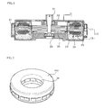
- FIG.1 is a cross-sectional view illustrating a motor according to a first exemplary embodiment of the present disclosure
- FIG.2 is a perspective view illustrating a stator core of FIG.1
- FIG.3 is a cross-sectional view illustrating a motor according to a second exemplary embodiment of the present disclosure
- FIG.4 is a plan view illustrating a stator core and an insulator according to a third exemplary embodiment of the present disclosure.
- the motor includes a housing (10), a stator (20) and a rotor (30).
- the housing (10) may include an upper housing (11) and a bottom housing (12), and a stator (20) wound with a plurality of coils may be installed inside a space formed by coupling of the upper housing (11) and the bottom housing (12).
- the stator (20) may include a stator core (21), an insulator (22) and a coil (23).
- the stator core (21) may be provided with a block of metal material, and may be formed by stacking a plurality of sheets of core members each formed with a thin plate.
- the stator core (21) may be protrusively formed with a plurality of teeth facing a surface opposite to the rotor (30) and each tooth is wound with the coil (23).
- the insulator (22) may be coupled to an upper surface and a bottom surface of the stator core (21) and serves to prevent the coil (23) wound on the teeth from being electrically conducted with the stator core (21).
- the insulator (22) may be formed with a resin material.
- the rotor (30) is rotatably formed at a center of the stator (20) by a rotation shaft (31).
- the rotor (30) may be formed by a magnet being coupled to a rotor core, and in some instances, the rotor core and the magnet may be integrally formed.
- Both distal ends of the rotation shaft (31) are preferably and rotatably supported by a bearing (32).
- An upper surface of the rotor (30) may be installed with a plate coupled to a sensing magnet for obtaining position information of the rotor (30), or may be installed with rotor position detecting means similar to the sensing magnet.
- the characteristic of the present disclosure lies in a configuration for preventing resonance of the stator (20) installed inside a space of the housing (10), and may be divided into the following exemplary embodiments.
- the insulator (22)-equipped stator (20) may be coated at an outside wound with the coil (23), with an insulation member (100) to allow the outside of the stator (20) to be wrapped with the insulation member (100), as illustrated in FIGS. 1 and 2 , and the space of the stator (20) inside the housing (10) may be fully filled with the stator (20) wound with the insulation member (100), as shown in FIG.1 .
- an intrinsic frequency of the stator (20) is changed as the stator (20) is coated with the insulation member (100) to thereby reduce vibration caused by the resonance.
- the insulation member (100) wrapping the stator (20) may surface-contact an inner surface of the upper and bottom housings (11, 12) to cause the vibration generated by electromagnetic force of the rotor (30) and the stator (20) to be absorbed by the insulation member (100) and the upper and bottom housings (11, 12).
- the vibration of the stator (20) generated in the course of motor operation can be restricted to enhance a reduced noise and operational reliability of a motor.
- FIG.3 is a cross-sectional view illustrating a motor according to a second exemplary embodiment of the present disclosure.
- a surface opposite to the upper housing (11) of the insulator (22) may be formed with a first pressure rib (210) extensively formed as long as a length capable of surface-contacting an inner surface of the upper housing (11) to allow the first pressure rib (210) to surface-contact all the inner surface of the upper housing (11).
- a floor surface facing the insulator (22) of the bottom housing (12) may be protrusively formed with a ring-shaped second pressure rib (220) applying a pressure to the insulator (22).
- the second pressure rib (220) may be formed at a position corresponding to a floor surface of the insulator (220) wrapping the teeth as illustrated in FIG.3 .
- the present disclosure is not limited thereto.
- the second pressure rib (220) may be formed at any place configured to support the floor surface of the insulator (22).
- an upper surface of the insulator (22) may surface-contact the upper housing (11) via the first pressure rib (210), and a bottom surface of the insulator (22) may surface-contact the bottom housing (12) via the second pressure rib (220) to reduce the vibration caused by the resonance as the intrinsic frequency of the stator core (21) is changed. Furthermore, the vibration that may be generated by the electromagnetic force of the rotor (30) and the stator (20) may be absorbed by the insulation member (100) and the upper and bottom housings (11, 12) as the inner surface of the upper and bottom housings (11, 12) is surface-contacted with the insulator (22).
- the vibration of the stator (20) that may be generated in the course of motor operation can be restricted to enhance the reduced noise and operational reliability of motor.
- FIG.4 is a plan view illustrating a stator core and an insulator according to a third exemplary embodiment of the present disclosure.
- the insulator (22) is configured to wrap the teeth formed at the stator core (21), such that in a case the teeth are wound with the coil (23), the stator core (21) is prevented from being short-circuited.
- a surface facing the teeth and the rotor (30) is exposed with the teeth of the stator core (21) and each tooth is spaced apart from the other tooth at a predetermined distance.
- a contact unit (300) may be formed in which tooth portions of the insulator (22) wrapping the teeth are mutually touched, while maintaining each of the spaced-apart distances of the teeth unchanged.
- the insulators (22) wrapping each tooth are mutually connected at the contact unit (300), whereby vibration that may be generated from the stator core (21) can be absorbed by the contact unit (300) of the insulator (22) to reduce the vibration that may be generated in the course of motor operation.
Landscapes
- Engineering & Computer Science (AREA)
- Power Engineering (AREA)
- Iron Core Of Rotating Electric Machines (AREA)
- Insulation, Fastening Of Motor, Generator Windings (AREA)
- Motor Or Generator Frames (AREA)
Abstract
Description
- The present application is based on, and claims priority from, Korean Application Number
10-2012-0064172, filed on June 15 2012 - The present disclosure relates to a motor having a stator and a rotor.
- Generally, almost every vehicle employs an electric power-assist steering system. Such an electric power-assist steering system generates an assist force based on the steering torque and the steering angle, so as to enhance the steering performance of the vehicle.
- That is, a steering system that assists a steering force of a vehicle with a separate power is used to enhance the motion stability of a vehicle.
- Conventionally, the auxiliary steering device uses hydraulic pressure, but an Electronic Power Steering (EPS) system adapted to transmit a rotation output of an electric motor to a steering shaft via a speed reduction mechanism has been increasingly employed these days from a viewpoint of a reduction in engine load, a reduction in weight, an enhanced steering stability and a quick restoring force.
- The EPS system is such that an Electronic Control Unit (ECU) drives a motor in response to steering conditions detected by a speed sensor, a torque angle sensor and a torque sensor to enhance a steering stability and provide a quick restoring force, whereby a driver can safely steer a vehicle.
- The EPS system is also such that a motor assists a torque manipulating a steering wheel to allow a driver to steer a vehicle with less power, where the motor employs a Brushless Direct Current (BLDC) motor.
- The BLDC motors have been increasingly used because the brushless motors are excellent in maintenance property, have a small size, and are capable of generating a high torque.
- The BLDC motor generally forms an exterior look by coupling of a housing and a cover member, an inner circumferential surface of the housing is provided with a stator, and the stator is centrally formed with a rotor rotatably mounted in electrical interaction with the stator. The rotor is rotatably supported by a rotation shaft, and an upper surface of the rotation shaft is connected by a steering shaft of a vehicle to provide a power assisting the steering of the vehicle as mentioned above.
- Meanwhile, the cover member is installed at an inside thereof with a PCB (Printed Circuit Board) mounted with a detection sensor provided in the form of a magnetic element. The detection sensor detects a magnetic force of a sensing magnet installed in a rotationally interlocking way with the rotor to learn a current position of the rotor.
- In general, the sensing magnet is fixed to an upper surface of a plate installed at an upper surface of the rotor using an adhesive. A rotor position can be detected by coupling the plate to a rotation shaft in response to a magnetic field direction, in a case the sensing magnet is magnetized to the plate.
- However, there may be generated a trembling or a resonance of a stator core due to electromagnetic force generated during rotation of a rotor. The trembling of the stator core by the resonance may result in an increased noise during operation of the motor, an erroneous operation and/or decreased performance.
- The present disclosure is directed to cope with the abovementioned problems/disadvantages and it is an object of the present disclosure to provide a structure-improved motor configured to reduce vibration of a stator core.
- In a first exemplary embodiment of the present disclosure, there is provided a motor, the motor comprising:
- a housing;
- a stator mounted on the housing and including a stator core having a plurality of teeth, an insulator and a coil;
- a rotor rotatably installed at a center of the stator by a rotation shaft; and
- an insulation member wrapping an entire surface except for a surface opposite to the rotor of the stator, wherein the insulation member is arranged therein with an insulator and a coil.
- Preferably, but not necessarily, the insulation member may be formed with any one of a rubber, silicone and an epoxy molding.
- Preferably, but not necessarily, the stator coated at an outside with the insulation member may take a shape of a ring flat at an upper surface and a bottom surface.
- In a second exemplary embodiment of the present disclosure, there is provided a motor, the motor comprising:
- a housing;
- a stator mounted on the housing and including a stator core having a plurality of teeth, an insulator and a coil;
- a rotor rotatably installed at a center of the stator by a rotation shaft; and
- a vibration prevention unit installed between the stator and the housing to prevent generation of vibration by regulating a movement of the stator.
- Preferably, but not necessarily, the housing may include an upper housing and a bottom housing, and the vibration prevention unit may include a first pressure rib interposed between the insulator and the upper housing to apply pressure to the insulator, and a second pressure rib interposed between the insulator and the bottom housing to apply a pressure to the insulator.
- Preferably, but not necessarily, each of the first and second pressure ribs may be brought into contact with each object.
- Preferably, but not necessarily, the first pressure rib may be extensively and integrally formed with a surface opposite to the upper housing of the insulator.
- Preferably, but not necessarily, the second pressure rib may be protrusively formed at a surface opposite to the insulator of the bottom housing to support a floor surface of the insulator.
- In a third exemplary embodiment of the present disclosure, there is provided a motor, the motor comprising:
- a housing;
- a stator mounted on the housing and including a stator core having a plurality of teeth, each tooth distanced from the other tooth at a predetermined distance, an insulator and a coil;
- a rotor rotatably installed at a center of the stator by a rotation shaft; and
- a contact unit formed by mutual connection of each distal end of a portion wrapping the tooth of the insulator, wherein vibration of the stator core is absorbed by the contact unit.
- Preferably, but not necessarily, the motor may further comprise an insulation member wrapping an entire surface except for a surface opposite to the rotor of the stator, wherein the configuration of the motor is same as that of the first embodiment.
- Preferably, but not necessarily, the motor may further comprise a vibration prevention unit installed between the stator and the housing to prevent generation of vibration by regulating a movement of the stator, wherein the configuration of the motor is same as that of the second exemplary embodiment.
- In an advantageous effect, a motor according to an exemplary embodiment of the present disclosure can prevent generation of resonance occurring on a stator core to reduce an operational noise of the motor, to prevent occurrence of erroneous operation of the motor caused by resonance of the stator core and to prevent generation of decreased performance.
-
-
FIG.1 is a cross-sectional view illustrating a motor according to a first exemplary embodiment of the present disclosure. -
FIG.2 is a perspective view illustrating a stator core ofFIG.1 . -
FIG.3 is a cross-sectional view illustrating a motor according to a second exemplary embodiment of the present disclosure. -
FIG.4 is a plan view illustrating a stator core and an insulator according to a third exemplary embodiment of the present disclosure. - Now, a motor according to the exemplary embodiments of the present disclosure will be described in detail with reference to the accompanying drawings.
-
FIG.1 is a cross-sectional view illustrating a motor according to a first exemplary embodiment of the present disclosure,FIG.2 is a perspective view illustrating a stator core ofFIG.1 ,FIG.3 is a cross-sectional view illustrating a motor according to a second exemplary embodiment of the present disclosure, andFIG.4 is a plan view illustrating a stator core and an insulator according to a third exemplary embodiment of the present disclosure. - Referring to
FIG.1 , the motor includes a housing (10), a stator (20) and a rotor (30). The housing (10) may include an upper housing (11) and a bottom housing (12), and a stator (20) wound with a plurality of coils may be installed inside a space formed by coupling of the upper housing (11) and the bottom housing (12). The stator (20) may include a stator core (21), an insulator (22) and a coil (23). - The stator core (21) may be provided with a block of metal material, and may be formed by stacking a plurality of sheets of core members each formed with a thin plate. The stator core (21) may be protrusively formed with a plurality of teeth facing a surface opposite to the rotor (30) and each tooth is wound with the coil (23).
- The insulator (22) may be coupled to an upper surface and a bottom surface of the stator core (21) and serves to prevent the coil (23) wound on the teeth from being electrically conducted with the stator core (21). The insulator (22) may be formed with a resin material.
- The rotor (30) is rotatably formed at a center of the stator (20) by a rotation shaft (31). The rotor (30) may be formed by a magnet being coupled to a rotor core, and in some instances, the rotor core and the magnet may be integrally formed.
- Both distal ends of the rotation shaft (31) are preferably and rotatably supported by a bearing (32). An upper surface of the rotor (30) may be installed with a plate coupled to a sensing magnet for obtaining position information of the rotor (30), or may be installed with rotor position detecting means similar to the sensing magnet.
- The characteristic of the present disclosure lies in a configuration for preventing resonance of the stator (20) installed inside a space of the housing (10), and may be divided into the following exemplary embodiments.
- According to a first exemplary embodiment of the present disclosure, the insulator (22)-equipped stator (20) may be coated at an outside wound with the coil (23), with an insulation member (100) to allow the outside of the stator (20) to be wrapped with the insulation member (100), as illustrated in
FIGS. 1 and 2 , and the space of the stator (20) inside the housing (10) may be fully filled with the stator (20) wound with the insulation member (100), as shown inFIG.1 . - According to the configuration thus illustrated, an intrinsic frequency of the stator (20) is changed as the stator (20) is coated with the insulation member (100) to thereby reduce vibration caused by the resonance. In addition, the insulation member (100) wrapping the stator (20) may surface-contact an inner surface of the upper and bottom housings (11, 12) to cause the vibration generated by electromagnetic force of the rotor (30) and the stator (20) to be absorbed by the insulation member (100) and the upper and bottom housings (11, 12). Thus, the vibration of the stator (20) generated in the course of motor operation can be restricted to enhance a reduced noise and operational reliability of a motor.
-
FIG.3 is a cross-sectional view illustrating a motor according to a second exemplary embodiment of the present disclosure. - Referring to
FIG.2 , most of the configurations according to the second exemplary embodiment are same as those of the first embodiment, except that shapes of the insulator (22) and the bottom housing (12) are partially changed and a vibration prevention unit (200) is added. - That is, a surface opposite to the upper housing (11) of the insulator (22) may be formed with a first pressure rib (210) extensively formed as long as a length capable of surface-contacting an inner surface of the upper housing (11) to allow the first pressure rib (210) to surface-contact all the inner surface of the upper housing (11). In addition, a floor surface facing the insulator (22) of the bottom housing (12) may be protrusively formed with a ring-shaped second pressure rib (220) applying a pressure to the insulator (22).
- The second pressure rib (220) may be formed at a position corresponding to a floor surface of the insulator (220) wrapping the teeth as illustrated in
FIG.3 . The present disclosure is not limited thereto. Alternatively, the second pressure rib (220) may be formed at any place configured to support the floor surface of the insulator (22). - According to the configuration thus described, an upper surface of the insulator (22) may surface-contact the upper housing (11) via the first pressure rib (210), and a bottom surface of the insulator (22) may surface-contact the bottom housing (12) via the second pressure rib (220) to reduce the vibration caused by the resonance as the intrinsic frequency of the stator core (21) is changed. Furthermore, the vibration that may be generated by the electromagnetic force of the rotor (30) and the stator (20) may be absorbed by the insulation member (100) and the upper and bottom housings (11, 12) as the inner surface of the upper and bottom housings (11, 12) is surface-contacted with the insulator (22).
- Hence, the vibration of the stator (20) that may be generated in the course of motor operation can be restricted to enhance the reduced noise and operational reliability of motor.
-
FIG.4 is a plan view illustrating a stator core and an insulator according to a third exemplary embodiment of the present disclosure. - Referring to
FIG.4 , the insulator (22) is configured to wrap the teeth formed at the stator core (21), such that in a case the teeth are wound with the coil (23), the stator core (21) is prevented from being short-circuited. - However, a surface facing the teeth and the rotor (30) is exposed with the teeth of the stator core (21) and each tooth is spaced apart from the other tooth at a predetermined distance. In the third exemplary embodiment of the present disclosure, a contact unit (300) may be formed in which tooth portions of the insulator (22) wrapping the teeth are mutually touched, while maintaining each of the spaced-apart distances of the teeth unchanged.
- According to the configuration above mentioned, the insulators (22) wrapping each tooth are mutually connected at the contact unit (300), whereby vibration that may be generated from the stator core (21) can be absorbed by the contact unit (300) of the insulator (22) to reduce the vibration that may be generated in the course of motor operation.
- Although embodiments have been described with reference to a number of illustrative embodiments thereof, it should be understood that numerous other modifications and embodiments can be devised by those skilled in the art that will fall within the spirit and scope of the principles of this disclosure. More particularly, various variations and modifications are possible in the component parts and/or arrangements of the subject combination arrangement within the scope of the disclosure, the drawings and the appended claims.
Claims (15)
- A motor, the motor characterized by:a housing (10);a stator (20) mounted on the housing (10) and including a stator core (21) having a plurality of teeth, an insulator (22) and a coil (23);a rotor (30) rotatably installed at a center of the stator (20) by a rotation shaft (31); andan insulation member (100) wrapping an entire surface except for a surface opposite to the rotor (30) of the stator (20), wherein the insulation member (100) is arranged therein with an insulator (22) and a coil (23).
- The motor of claim 1, characterized in that the insulation member (100) is formed with any one of a rubber, silicone and an epoxy molding.
- The motor of claim 1, characterized in that the stator (20) coated at an outside with insulation member (100) takes a shape of a ring flat at an upper surface and a bottom surface.
- The motor of claim 1, further characterized by a vibration prevention unit (200) installed between the stator (20) and the housing (10) to prevent generation of vibration by regulating a movement of the stator (20), wherein the housing (10) includes an upper housing (11) and a bottom housing (12), and the vibration prevention unit (200) includes a first pressure rib (210) interposed between the insulator (22) and the upper housing (11) to apply pressure to the insulator (22), and a second pressure rib (220) interposed between the insulator (22) and the bottom housing (12) to apply a pressure to the insulator (22).
- The motor of claim 4, characterized in that each of the first and second pressure ribs (210, 220) is brought into contact with each object.
- The motor of claim 4, characterized in that the first pressure rib (210) is extensively and integrally formed with a surface opposite to the upper housing (11) of the insulator (22).
- The motor of claim 4, characterized in that the second pressure rib (220) is protrusively formed at a surface opposite to the insulator (22) of the bottom housing to support a floor surface of the insulator (22).
- The motor of claim 1, further characterized by a contact unit (300) formed by mutual connection of each distal end of a portion wrapping the tooth of the insulator (22), wherein vibration of the stator core (21) is absorbed by the contact unit (300).
- The motor of claim 8, further characterized by an insulation member (100) wrapping an entire surface except for a surface opposite to the rotor (30) of the stator (20), wherein the insulation member (100) is arranged therein with the insulator (22) and the coil (23).
- The motor of claim 9, characterized in that the insulation member (100) is formed with any one of a rubber, silicone and an epoxy molding.
- The motor of claim 8, characterized in that the stator (20) coated at an outside with the insulation member (100) takes a shape of a ring flat at an upper surface and a bottom surface.
- The motor of claim 8, further characterized by a vibration prevention unit (200) installed between the stator (20) and the housing (10) to prevent generation of vibration by regulating a movement of the stator (20).
- The motor of claim 12, characterized in that the housing (10) includes an upper housing (11) and a bottom housing (12), and the vibration prevention unit (200) includes a first pressure rib (210) interposed between the insulator (22) and the upper housing (11) to apply pressure to the insulator (22), and a second pressure rib (220) interposed between the insulator (22) and the bottom housing (12) to apply a pressure to the insulator (22).
- The motor of claim 13, characterized in that each of the first and second pressure ribs (210, 220) is brought into contact with each object.
- The motor of claim 13, characterized in that the first pressure rib (210) is extensively and integrally formed with a surface opposite to the upper housing (11) of the insulator (22), and the second pressure rib (220) is protrusively formed at a surface opposite to the insulator (22) of the bottom housing to support a floor surface of the insulator (22).
Applications Claiming Priority (1)
| Application Number | Priority Date | Filing Date | Title |
|---|---|---|---|
| KR1020120064172A KR101930333B1 (en) | 2012-06-15 | 2012-06-15 | Motor |
Publications (3)
| Publication Number | Publication Date |
|---|---|
| EP2675042A2 true EP2675042A2 (en) | 2013-12-18 |
| EP2675042A3 EP2675042A3 (en) | 2017-05-17 |
| EP2675042B1 EP2675042B1 (en) | 2021-08-04 |
Family
ID=48577621
Family Applications (1)
| Application Number | Title | Priority Date | Filing Date |
|---|---|---|---|
| EP13171563.3A Active EP2675042B1 (en) | 2012-06-15 | 2013-06-11 | Motor |
Country Status (5)
| Country | Link |
|---|---|
| US (1) | US20130334909A1 (en) |
| EP (1) | EP2675042B1 (en) |
| JP (1) | JP6243635B2 (en) |
| KR (1) | KR101930333B1 (en) |
| CN (1) | CN103516120B (en) |
Families Citing this family (2)
| Publication number | Priority date | Publication date | Assignee | Title |
|---|---|---|---|---|
| JP6395751B2 (en) * | 2016-03-30 | 2018-09-26 | 三菱電機株式会社 | Rotating electric machine and electric power steering apparatus |
| KR102191128B1 (en) * | 2019-04-05 | 2020-12-16 | 엘지전자 주식회사 | Motor part and electric compressor including the same |
Family Cites Families (22)
| Publication number | Priority date | Publication date | Assignee | Title |
|---|---|---|---|---|
| US2668925A (en) * | 1949-04-05 | 1954-02-09 | Kearfott Company Inc | Electric machine construction |
| US3465182A (en) * | 1967-04-12 | 1969-09-02 | Gen Electric | Motor vibration suppression mounting system |
| JPH01138936A (en) * | 1988-08-27 | 1989-05-31 | Shibaura Eng Works Co Ltd | Manufacture of induction motor stator |
| JPH0515101A (en) * | 1991-06-28 | 1993-01-22 | Asmo Co Ltd | Resin-molded type rotating electric machine |
| JPH06261528A (en) * | 1993-03-08 | 1994-09-16 | Matsushita Electric Ind Co Ltd | Stepping motor |
| JP2000188841A (en) * | 1998-12-21 | 2000-07-04 | Matsushita Electric Ind Co Ltd | DC brushless motor |
| JP2000217302A (en) * | 1999-01-19 | 2000-08-04 | Nippon Densan Corp | Motor |
| JP4076714B2 (en) * | 2000-09-04 | 2008-04-16 | 三菱電機株式会社 | Motor stator, motor, DC brushless motor, and air conditioner |
| US7036207B2 (en) * | 2001-03-02 | 2006-05-02 | Encap Motor Corporation | Stator assembly made from a plurality of toroidal core segments and motor using same |
| JP3882721B2 (en) * | 2002-09-13 | 2007-02-21 | 日産自動車株式会社 | Cooling structure for rotating electrical machine and method for manufacturing the same |
| JP3987413B2 (en) * | 2002-10-22 | 2007-10-10 | ミネベア株式会社 | motor |
| JP4627701B2 (en) * | 2005-08-10 | 2011-02-09 | 日立オートモティブシステムズ株式会社 | Rotating electric machine |
| TWI280322B (en) * | 2005-12-23 | 2007-05-01 | Delta Electronics Inc | Fan and motor thereof |
| JP2007189812A (en) * | 2006-01-12 | 2007-07-26 | Toyota Motor Corp | Inner rotor type brushless motor |
| JP2007318924A (en) * | 2006-05-26 | 2007-12-06 | Sanden Corp | Stator fixing structure of electric motor |
| JP4680875B2 (en) * | 2006-12-11 | 2011-05-11 | 三菱電機株式会社 | Stator core manufacturing method |
| JP2009232658A (en) * | 2008-03-25 | 2009-10-08 | Asmo Co Ltd | Rotating electric machine |
| JP5347380B2 (en) * | 2008-08-28 | 2013-11-20 | アイシン精機株式会社 | Oil cooling structure of motor |
| TWI373903B (en) * | 2008-09-23 | 2012-10-01 | Sunonwealth Electr Mach Ind Co | Inner-rotor type fan |
| CN101771298A (en) * | 2008-12-26 | 2010-07-07 | 三洋电机株式会社 | Molded motor and electric vehicle |
| JP5630650B2 (en) * | 2010-01-12 | 2014-11-26 | 日本電産株式会社 | Motor and motor manufacturing method |
| JP5216038B2 (en) * | 2010-03-25 | 2013-06-19 | 株式会社日立製作所 | Rotating motor |
-
2012
- 2012-06-15 KR KR1020120064172A patent/KR101930333B1/en active Active
-
2013
- 2013-06-11 EP EP13171563.3A patent/EP2675042B1/en active Active
- 2013-06-11 JP JP2013122561A patent/JP6243635B2/en active Active
- 2013-06-13 US US13/917,076 patent/US20130334909A1/en not_active Abandoned
- 2013-06-14 CN CN201310234850.3A patent/CN103516120B/en active Active
Non-Patent Citations (1)
| Title |
|---|
| None |
Also Published As
| Publication number | Publication date |
|---|---|
| EP2675042A3 (en) | 2017-05-17 |
| EP2675042B1 (en) | 2021-08-04 |
| JP6243635B2 (en) | 2017-12-06 |
| JP2014003885A (en) | 2014-01-09 |
| KR20130141076A (en) | 2013-12-26 |
| US20130334909A1 (en) | 2013-12-19 |
| KR101930333B1 (en) | 2018-12-18 |
| CN103516120A (en) | 2014-01-15 |
| CN103516120B (en) | 2018-09-04 |
Similar Documents
| Publication | Publication Date | Title |
|---|---|---|
| KR102146023B1 (en) | Motor and electronic power steering system having the same | |
| US20160352160A1 (en) | Stator and Motor Using the Same | |
| US8791610B2 (en) | Anti-separating structure of sensing magnet for EPS motor | |
| CN107251372A (en) | The rotor and motor of electric rotating machine | |
| CN110268606B (en) | Electric machine | |
| US9973054B2 (en) | Motor with damper member on bearing | |
| JP5523044B2 (en) | Drive control device and motor unit | |
| US20130134824A1 (en) | Stator core | |
| KR101966620B1 (en) | Stator and motor using the same | |
| EP2675042B1 (en) | Motor | |
| US20200169138A1 (en) | Motor | |
| KR102355645B1 (en) | Motor | |
| KR20160010820A (en) | Direct current motor without contacting power supplier | |
| KR102488442B1 (en) | Motor apparatus | |
| KR20180092423A (en) | Motor | |
| KR102311773B1 (en) | coil insulation securing structure for motor stator | |
| KR102477861B1 (en) | Motor and appartus for steering | |
| KR20180089173A (en) | Motor | |
| KR102257691B1 (en) | Motor and electronic power steering system having the same | |
| KR20180087684A (en) | Motor | |
| KR20200026619A (en) | Motor | |
| KR20180083535A (en) | Motor | |
| KR20180122176A (en) | Motor | |
| KR20190093352A (en) | Motor | |
| KR20180091279A (en) | Motor |
Legal Events
| Date | Code | Title | Description |
|---|---|---|---|
| PUAI | Public reference made under article 153(3) epc to a published international application that has entered the european phase |
Free format text: ORIGINAL CODE: 0009012 |
|
| AK | Designated contracting states |
Kind code of ref document: A2 Designated state(s): AL AT BE BG CH CY CZ DE DK EE ES FI FR GB GR HR HU IE IS IT LI LT LU LV MC MK MT NL NO PL PT RO RS SE SI SK SM TR |
|
| AX | Request for extension of the european patent |
Extension state: BA ME |
|
| 17P | Request for examination filed |
Effective date: 20140328 |
|
| RBV | Designated contracting states (corrected) |
Designated state(s): AL AT BE BG CH CY CZ DE DK EE ES FI FR GB GR HR HU IE IS IT LI LT LU LV MC MK MT NL NO PL PT RO RS SE SI SK SM TR |
|
| RAP1 | Party data changed (applicant data changed or rights of an application transferred) |
Owner name: LG INNOTEK CO., LTD. |
|
| PUAL | Search report despatched |
Free format text: ORIGINAL CODE: 0009013 |
|
| AK | Designated contracting states |
Kind code of ref document: A3 Designated state(s): AL AT BE BG CH CY CZ DE DK EE ES FI FR GB GR HR HU IE IS IT LI LT LU LV MC MK MT NL NO PL PT RO RS SE SI SK SM TR |
|
| AX | Request for extension of the european patent |
Extension state: BA ME |
|
| RAP1 | Party data changed (applicant data changed or rights of an application transferred) |
Owner name: LG INNOTEK CO., LTD. |
|
| RIC1 | Information provided on ipc code assigned before grant |
Ipc: H02K 5/24 20060101ALI20170411BHEP Ipc: H02K 5/08 20060101AFI20170411BHEP |
|
| GRAP | Despatch of communication of intention to grant a patent |
Free format text: ORIGINAL CODE: EPIDOSNIGR1 |
|
| STAA | Information on the status of an ep patent application or granted ep patent |
Free format text: STATUS: GRANT OF PATENT IS INTENDED |
|
| INTG | Intention to grant announced |
Effective date: 20210128 |
|
| GRAS | Grant fee paid |
Free format text: ORIGINAL CODE: EPIDOSNIGR3 |
|
| GRAA | (expected) grant |
Free format text: ORIGINAL CODE: 0009210 |
|
| STAA | Information on the status of an ep patent application or granted ep patent |
Free format text: STATUS: THE PATENT HAS BEEN GRANTED |
|
| AK | Designated contracting states |
Kind code of ref document: B1 Designated state(s): AL AT BE BG CH CY CZ DE DK EE ES FI FR GB GR HR HU IE IS IT LI LT LU LV MC MK MT NL NO PL PT RO RS SE SI SK SM TR |
|
| REG | Reference to a national code |
Ref country code: GB Ref legal event code: FG4D |
|
| REG | Reference to a national code |
Ref country code: AT Ref legal event code: REF Ref document number: 1418009 Country of ref document: AT Kind code of ref document: T Effective date: 20210815 |
|
| REG | Reference to a national code |
Ref country code: CH Ref legal event code: EP |
|
| REG | Reference to a national code |
Ref country code: DE Ref legal event code: R096 Ref document number: 602013078610 Country of ref document: DE |
|
| REG | Reference to a national code |
Ref country code: IE Ref legal event code: FG4D |
|
| REG | Reference to a national code |
Ref country code: NL Ref legal event code: FP |
|
| REG | Reference to a national code |
Ref country code: LT Ref legal event code: MG9D |
|
| REG | Reference to a national code |
Ref country code: AT Ref legal event code: MK05 Ref document number: 1418009 Country of ref document: AT Kind code of ref document: T Effective date: 20210804 |
|
| PG25 | Lapsed in a contracting state [announced via postgrant information from national office to epo] |
Ref country code: LT Free format text: LAPSE BECAUSE OF FAILURE TO SUBMIT A TRANSLATION OF THE DESCRIPTION OR TO PAY THE FEE WITHIN THE PRESCRIBED TIME-LIMIT Effective date: 20210804 Ref country code: BG Free format text: LAPSE BECAUSE OF FAILURE TO SUBMIT A TRANSLATION OF THE DESCRIPTION OR TO PAY THE FEE WITHIN THE PRESCRIBED TIME-LIMIT Effective date: 20211104 Ref country code: AT Free format text: LAPSE BECAUSE OF FAILURE TO SUBMIT A TRANSLATION OF THE DESCRIPTION OR TO PAY THE FEE WITHIN THE PRESCRIBED TIME-LIMIT Effective date: 20210804 Ref country code: ES Free format text: LAPSE BECAUSE OF FAILURE TO SUBMIT A TRANSLATION OF THE DESCRIPTION OR TO PAY THE FEE WITHIN THE PRESCRIBED TIME-LIMIT Effective date: 20210804 Ref country code: FI Free format text: LAPSE BECAUSE OF FAILURE TO SUBMIT A TRANSLATION OF THE DESCRIPTION OR TO PAY THE FEE WITHIN THE PRESCRIBED TIME-LIMIT Effective date: 20210804 Ref country code: NO Free format text: LAPSE BECAUSE OF FAILURE TO SUBMIT A TRANSLATION OF THE DESCRIPTION OR TO PAY THE FEE WITHIN THE PRESCRIBED TIME-LIMIT Effective date: 20211104 Ref country code: RS Free format text: LAPSE BECAUSE OF FAILURE TO SUBMIT A TRANSLATION OF THE DESCRIPTION OR TO PAY THE FEE WITHIN THE PRESCRIBED TIME-LIMIT Effective date: 20210804 Ref country code: PT Free format text: LAPSE BECAUSE OF FAILURE TO SUBMIT A TRANSLATION OF THE DESCRIPTION OR TO PAY THE FEE WITHIN THE PRESCRIBED TIME-LIMIT Effective date: 20211206 Ref country code: HR Free format text: LAPSE BECAUSE OF FAILURE TO SUBMIT A TRANSLATION OF THE DESCRIPTION OR TO PAY THE FEE WITHIN THE PRESCRIBED TIME-LIMIT Effective date: 20210804 Ref country code: SE Free format text: LAPSE BECAUSE OF FAILURE TO SUBMIT A TRANSLATION OF THE DESCRIPTION OR TO PAY THE FEE WITHIN THE PRESCRIBED TIME-LIMIT Effective date: 20210804 |
|
| PG25 | Lapsed in a contracting state [announced via postgrant information from national office to epo] |
Ref country code: PL Free format text: LAPSE BECAUSE OF FAILURE TO SUBMIT A TRANSLATION OF THE DESCRIPTION OR TO PAY THE FEE WITHIN THE PRESCRIBED TIME-LIMIT Effective date: 20210804 Ref country code: LV Free format text: LAPSE BECAUSE OF FAILURE TO SUBMIT A TRANSLATION OF THE DESCRIPTION OR TO PAY THE FEE WITHIN THE PRESCRIBED TIME-LIMIT Effective date: 20210804 Ref country code: GR Free format text: LAPSE BECAUSE OF FAILURE TO SUBMIT A TRANSLATION OF THE DESCRIPTION OR TO PAY THE FEE WITHIN THE PRESCRIBED TIME-LIMIT Effective date: 20211105 |
|
| PG25 | Lapsed in a contracting state [announced via postgrant information from national office to epo] |
Ref country code: DK Free format text: LAPSE BECAUSE OF FAILURE TO SUBMIT A TRANSLATION OF THE DESCRIPTION OR TO PAY THE FEE WITHIN THE PRESCRIBED TIME-LIMIT Effective date: 20210804 |
|
| REG | Reference to a national code |
Ref country code: DE Ref legal event code: R097 Ref document number: 602013078610 Country of ref document: DE |
|
| PG25 | Lapsed in a contracting state [announced via postgrant information from national office to epo] |
Ref country code: SM Free format text: LAPSE BECAUSE OF FAILURE TO SUBMIT A TRANSLATION OF THE DESCRIPTION OR TO PAY THE FEE WITHIN THE PRESCRIBED TIME-LIMIT Effective date: 20210804 Ref country code: SK Free format text: LAPSE BECAUSE OF FAILURE TO SUBMIT A TRANSLATION OF THE DESCRIPTION OR TO PAY THE FEE WITHIN THE PRESCRIBED TIME-LIMIT Effective date: 20210804 Ref country code: RO Free format text: LAPSE BECAUSE OF FAILURE TO SUBMIT A TRANSLATION OF THE DESCRIPTION OR TO PAY THE FEE WITHIN THE PRESCRIBED TIME-LIMIT Effective date: 20210804 Ref country code: EE Free format text: LAPSE BECAUSE OF FAILURE TO SUBMIT A TRANSLATION OF THE DESCRIPTION OR TO PAY THE FEE WITHIN THE PRESCRIBED TIME-LIMIT Effective date: 20210804 Ref country code: CZ Free format text: LAPSE BECAUSE OF FAILURE TO SUBMIT A TRANSLATION OF THE DESCRIPTION OR TO PAY THE FEE WITHIN THE PRESCRIBED TIME-LIMIT Effective date: 20210804 Ref country code: AL Free format text: LAPSE BECAUSE OF FAILURE TO SUBMIT A TRANSLATION OF THE DESCRIPTION OR TO PAY THE FEE WITHIN THE PRESCRIBED TIME-LIMIT Effective date: 20210804 |
|
| PLBE | No opposition filed within time limit |
Free format text: ORIGINAL CODE: 0009261 |
|
| STAA | Information on the status of an ep patent application or granted ep patent |
Free format text: STATUS: NO OPPOSITION FILED WITHIN TIME LIMIT |
|
| 26N | No opposition filed |
Effective date: 20220506 |
|
| PG25 | Lapsed in a contracting state [announced via postgrant information from national office to epo] |
Ref country code: IT Free format text: LAPSE BECAUSE OF FAILURE TO SUBMIT A TRANSLATION OF THE DESCRIPTION OR TO PAY THE FEE WITHIN THE PRESCRIBED TIME-LIMIT Effective date: 20210804 |
|
| PG25 | Lapsed in a contracting state [announced via postgrant information from national office to epo] |
Ref country code: SI Free format text: LAPSE BECAUSE OF FAILURE TO SUBMIT A TRANSLATION OF THE DESCRIPTION OR TO PAY THE FEE WITHIN THE PRESCRIBED TIME-LIMIT Effective date: 20210804 |
|
| PG25 | Lapsed in a contracting state [announced via postgrant information from national office to epo] |
Ref country code: MC Free format text: LAPSE BECAUSE OF FAILURE TO SUBMIT A TRANSLATION OF THE DESCRIPTION OR TO PAY THE FEE WITHIN THE PRESCRIBED TIME-LIMIT Effective date: 20210804 |
|
| REG | Reference to a national code |
Ref country code: CH Ref legal event code: PL |
|
| REG | Reference to a national code |
Ref country code: BE Ref legal event code: MM Effective date: 20220630 |
|
| GBPC | Gb: european patent ceased through non-payment of renewal fee |
Effective date: 20220611 |
|
| PG25 | Lapsed in a contracting state [announced via postgrant information from national office to epo] |
Ref country code: LU Free format text: LAPSE BECAUSE OF NON-PAYMENT OF DUE FEES Effective date: 20220611 Ref country code: LI Free format text: LAPSE BECAUSE OF NON-PAYMENT OF DUE FEES Effective date: 20220630 Ref country code: IE Free format text: LAPSE BECAUSE OF NON-PAYMENT OF DUE FEES Effective date: 20220611 Ref country code: CH Free format text: LAPSE BECAUSE OF NON-PAYMENT OF DUE FEES Effective date: 20220630 |
|
| PG25 | Lapsed in a contracting state [announced via postgrant information from national office to epo] |
Ref country code: GB Free format text: LAPSE BECAUSE OF NON-PAYMENT OF DUE FEES Effective date: 20220611 Ref country code: BE Free format text: LAPSE BECAUSE OF NON-PAYMENT OF DUE FEES Effective date: 20220630 |
|
| PG25 | Lapsed in a contracting state [announced via postgrant information from national office to epo] |
Ref country code: HU Free format text: LAPSE BECAUSE OF FAILURE TO SUBMIT A TRANSLATION OF THE DESCRIPTION OR TO PAY THE FEE WITHIN THE PRESCRIBED TIME-LIMIT; INVALID AB INITIO Effective date: 20130611 |
|
| PG25 | Lapsed in a contracting state [announced via postgrant information from national office to epo] |
Ref country code: MK Free format text: LAPSE BECAUSE OF FAILURE TO SUBMIT A TRANSLATION OF THE DESCRIPTION OR TO PAY THE FEE WITHIN THE PRESCRIBED TIME-LIMIT Effective date: 20210804 Ref country code: CY Free format text: LAPSE BECAUSE OF FAILURE TO SUBMIT A TRANSLATION OF THE DESCRIPTION OR TO PAY THE FEE WITHIN THE PRESCRIBED TIME-LIMIT Effective date: 20210804 |
|
| PG25 | Lapsed in a contracting state [announced via postgrant information from national office to epo] |
Ref country code: TR Free format text: LAPSE BECAUSE OF FAILURE TO SUBMIT A TRANSLATION OF THE DESCRIPTION OR TO PAY THE FEE WITHIN THE PRESCRIBED TIME-LIMIT Effective date: 20210804 |
|
| PG25 | Lapsed in a contracting state [announced via postgrant information from national office to epo] |
Ref country code: MT Free format text: LAPSE BECAUSE OF FAILURE TO SUBMIT A TRANSLATION OF THE DESCRIPTION OR TO PAY THE FEE WITHIN THE PRESCRIBED TIME-LIMIT Effective date: 20210804 |
|
| PGFP | Annual fee paid to national office [announced via postgrant information from national office to epo] |
Ref country code: NL Payment date: 20250520 Year of fee payment: 13 |
|
| PGFP | Annual fee paid to national office [announced via postgrant information from national office to epo] |
Ref country code: DE Payment date: 20250520 Year of fee payment: 13 |
|
| PGFP | Annual fee paid to national office [announced via postgrant information from national office to epo] |
Ref country code: FR Payment date: 20250521 Year of fee payment: 13 |