EP2674955A1 - Vacuum interrupter with double coaxial contact arrangement at each side - Google Patents
Vacuum interrupter with double coaxial contact arrangement at each side Download PDFInfo
- Publication number
- EP2674955A1 EP2674955A1 EP20120007203 EP12007203A EP2674955A1 EP 2674955 A1 EP2674955 A1 EP 2674955A1 EP 20120007203 EP20120007203 EP 20120007203 EP 12007203 A EP12007203 A EP 12007203A EP 2674955 A1 EP2674955 A1 EP 2674955A1
- Authority
- EP
- European Patent Office
- Prior art keywords
- vacuum interrupter
- contacts
- layer
- contact
- interrupter according
- Prior art date
- Legal status (The legal status is an assumption and is not a legal conclusion. Google has not performed a legal analysis and makes no representation as to the accuracy of the status listed.)
- Granted
Links
- 239000010410 layer Substances 0.000 claims abstract description 52
- 239000000463 material Substances 0.000 claims abstract description 14
- 229910000851 Alloy steel Inorganic materials 0.000 claims abstract description 7
- 229910000831 Steel Inorganic materials 0.000 claims abstract description 7
- 239000010959 steel Substances 0.000 claims abstract description 7
- 239000002356 single layer Substances 0.000 claims abstract description 4
- 239000010935 stainless steel Substances 0.000 claims description 22
- 229910001220 stainless steel Inorganic materials 0.000 claims description 22
- RYGMFSIKBFXOCR-UHFFFAOYSA-N Copper Chemical group [Cu] RYGMFSIKBFXOCR-UHFFFAOYSA-N 0.000 claims description 21
- 229910052802 copper Inorganic materials 0.000 claims description 21
- 239000010949 copper Substances 0.000 claims description 21
- PXHVJJICTQNCMI-UHFFFAOYSA-N Nickel Chemical compound [Ni] PXHVJJICTQNCMI-UHFFFAOYSA-N 0.000 claims description 6
- 238000000034 method Methods 0.000 claims description 5
- 230000000694 effects Effects 0.000 claims description 3
- 229910052759 nickel Inorganic materials 0.000 claims description 3
- 229910001316 Ag alloy Inorganic materials 0.000 claims 2
- 229910000881 Cu alloy Inorganic materials 0.000 claims 2
- 239000004332 silver Substances 0.000 claims 2
- BQCADISMDOOEFD-UHFFFAOYSA-N Silver Chemical compound [Ag] BQCADISMDOOEFD-UHFFFAOYSA-N 0.000 claims 1
- 229910052709 silver Inorganic materials 0.000 claims 1
- 238000010276 construction Methods 0.000 abstract description 2
- 239000004020 conductor Substances 0.000 description 5
- 239000011248 coating agent Substances 0.000 description 2
- 238000000576 coating method Methods 0.000 description 2
- 230000005489 elastic deformation Effects 0.000 description 2
- 238000005323 electroforming Methods 0.000 description 2
- 238000009713 electroplating Methods 0.000 description 2
- 238000005240 physical vapour deposition Methods 0.000 description 2
- 229910017813 Cu—Cr Inorganic materials 0.000 description 1
- 238000001816 cooling Methods 0.000 description 1
- 230000007423 decrease Effects 0.000 description 1
- 230000003247 decreasing effect Effects 0.000 description 1
- 239000013013 elastic material Substances 0.000 description 1
- 239000002184 metal Substances 0.000 description 1
- 229910052751 metal Inorganic materials 0.000 description 1
- 230000010363 phase shift Effects 0.000 description 1
- 230000000630 rising effect Effects 0.000 description 1
Images


Classifications
-
- H—ELECTRICITY
- H01—ELECTRIC ELEMENTS
- H01H—ELECTRIC SWITCHES; RELAYS; SELECTORS; EMERGENCY PROTECTIVE DEVICES
- H01H33/00—High-tension or heavy-current switches with arc-extinguishing or arc-preventing means
- H01H33/60—Switches wherein the means for extinguishing or preventing the arc do not include separate means for obtaining or increasing flow of arc-extinguishing fluid
- H01H33/66—Vacuum switches
- H01H33/664—Contacts; Arc-extinguishing means, e.g. arcing rings
-
- H—ELECTRICITY
- H01—ELECTRIC ELEMENTS
- H01H—ELECTRIC SWITCHES; RELAYS; SELECTORS; EMERGENCY PROTECTIVE DEVICES
- H01H33/00—High-tension or heavy-current switches with arc-extinguishing or arc-preventing means
- H01H33/60—Switches wherein the means for extinguishing or preventing the arc do not include separate means for obtaining or increasing flow of arc-extinguishing fluid
- H01H33/66—Vacuum switches
- H01H33/6606—Terminal arrangements
-
- H—ELECTRICITY
- H01—ELECTRIC ELEMENTS
- H01H—ELECTRIC SWITCHES; RELAYS; SELECTORS; EMERGENCY PROTECTIVE DEVICES
- H01H33/00—High-tension or heavy-current switches with arc-extinguishing or arc-preventing means
- H01H33/60—Switches wherein the means for extinguishing or preventing the arc do not include separate means for obtaining or increasing flow of arc-extinguishing fluid
- H01H33/66—Vacuum switches
- H01H33/664—Contacts; Arc-extinguishing means, e.g. arcing rings
- H01H33/6642—Contacts; Arc-extinguishing means, e.g. arcing rings having cup-shaped contacts, the cylindrical wall of which being provided with inclined slits to form a coil
-
- H—ELECTRICITY
- H01—ELECTRIC ELEMENTS
- H01H—ELECTRIC SWITCHES; RELAYS; SELECTORS; EMERGENCY PROTECTIVE DEVICES
- H01H33/00—High-tension or heavy-current switches with arc-extinguishing or arc-preventing means
- H01H33/60—Switches wherein the means for extinguishing or preventing the arc do not include separate means for obtaining or increasing flow of arc-extinguishing fluid
- H01H33/66—Vacuum switches
- H01H33/664—Contacts; Arc-extinguishing means, e.g. arcing rings
- H01H33/6643—Contacts; Arc-extinguishing means, e.g. arcing rings having disc-shaped contacts subdivided in petal-like segments, e.g. by helical grooves
-
- H—ELECTRICITY
- H01—ELECTRIC ELEMENTS
- H01H—ELECTRIC SWITCHES; RELAYS; SELECTORS; EMERGENCY PROTECTIVE DEVICES
- H01H2201/00—Contacts
- H01H2201/022—Material
- H01H2201/03—Composite
-
- H—ELECTRICITY
- H01—ELECTRIC ELEMENTS
- H01H—ELECTRIC SWITCHES; RELAYS; SELECTORS; EMERGENCY PROTECTIVE DEVICES
- H01H2203/00—Form of contacts
Definitions
- the invention relates to a vacuum interrupter with double contact arrangement within concentrically arranged contact parts at each side, th.m. on the side of the a fixed contact arrangement as well as on the side of a movable contact arrangement according to the preamble of claim 1.
- the inner contacts are responsible for nominal current conduction and thus should have a very small total resistance (contact and bulk resistances). For this reason, the inner contacts are TMF-like or Butt contacts and made from high electrical conductive material like copper or CuCr.
- the inner contacts following the state of the art description, hold the initial phase of the arc before its commutation to the outer contacts.
- the outer contacts are only responsible for the AMF field generation, thus can be designed with a thin cup-shaped layer made from hard conductive material like stainless-steel. This option offers many advantages over the conventional AMF contacts leading to lower material cost and very robust contacts assembly. These advantages are:
- the outer cup shaped contact is made from a single, double or multiple layer arrangement, wherein at least one layer is made from a hard steel or steel alloy and at least, in case of a multilayer arrangement, a second layer is made from material with high thermal conductivity.
- the material of high thermal conductivity is copper.
- a further advantageous embodiment is, that the hard steel or steel alloy is stainless steel.
- the inner layer of the double or multiple layer contact arrangement is made of stainless steel or another material with same stiffness, and the outer layer is made of copper.
- a further advantageous embodiment is, that in case of a cup shaped contact arrangement the inner layer of the contact arrangement is made of copper, and the other or in case of a cup shaped arrangement the outer layer is made of stainless steel.
- a further advantageous embodiment is, that the contact parts are positioned like that only the inner contacts are in touch when the vacuum interrupter is in closed position, and the whole nominal current flows through them.
- a further embodiment is, that the gap distance in opened position of the vacuuminterrupter between the inner contacts and the outer contacts is kept the same. But in closed position the quasitotality of nominal current flows through the inner contacts.
- a last advantageous embodiment is, that the gap distance between the outer contacts in opened position of the vacuum interrupter is smaller than the gap distance between the inner contacts. But in closed position a big part of nominal current flows through the inner contacts.
- electrode is the whole moving or fixed parts.
- An electrode in this case includes the combination of the inner and the outer contacts.
- the inner and/or outer contacts relative position can be classified according to the following variations:
- the electrode is designated to the whole moving or fixed parts.
- An electrode in this case includes the combination of the inner and the outer contacts.
- the inner and/or outer contacts relative position can be classified according to the following variations, like seen in figure 2 .
- the outer contact is made from a double or multiple layers in which one layer at least is made from a strong, elastic and conductive material like stainless steel, and at least a second layer made from high thermal conductivity material like copper.
- This combination offers both robustness and cost effectiveness criteria to the contact assembly and would guarantee a better thermal management during and after arcing (fast contacts cooling).
- the multi-layer cup-shaped contact may have several various arrangements on the superposition order of the layers depending on the intended application. For example for a double-layer:
Landscapes
- Contacts (AREA)
- High-Tension Arc-Extinguishing Switches Without Spraying Means (AREA)
Abstract
Description
- The invention relates to a vacuum interrupter with double contact arrangement within concentrically arranged contact parts at each side, th.m. on the side of the a fixed contact arrangement as well as on the side of a movable contact arrangement according to the preamble of
claim 1. - There have been constant improvements of many features of the double-contact Vacuuminterrupter concept designed for high current interruption and being cost effective vacuum interrupter. The most attractive feature of the double-contact assembly is the separate function between the nominal current conducting element, that means the inner contacts, and the current interrupting element that means the outer contacts. In this way each element can be designed independantly to its optimum shape and can be made from its best material.
- Such a double contact arrangement is known from the
EP 2 434 513 A1 - The outer contacts, are only responsible for the AMF field generation, thus can be designed with a thin cup-shaped layer made from hard conductive material like stainless-steel. This option offers many advantages over the conventional AMF contacts leading to lower material cost and very robust contacts assembly. These advantages are:
- 1. High mechanical strength
- 2. Lower cost material (stainless-steel instead of copper or CuCr)
- 3. Lower contacts mass- reducing the driving contacts opening forces
- 4. Large effective AMF area leading to a larger diffuse vacuum arc distribution
- So it is an object of the invention, to enhance this special construction furthermore in order to result high conductivity and low restistance.
- This is resulted by the invention in that the outer cup shaped contact is made from a single, double or multiple layer arrangement, wherein at least one layer is made from a hard steel or steel alloy and at least, in case of a multilayer arrangement, a second layer is made from material with high thermal conductivity.
- Advantageous is, that the material of high thermal conductivity is copper.
- A further advantageous embodiment is, that the hard steel or steel alloy is stainless steel.
- In a further advantageous embodiment the inner layer of the double or multiple layer contact arrangement is made of stainless steel or another material with same stiffness, and the outer layer is made of copper.
- A further advantageous embodiment is, that in case of a cup shaped contact arrangement the inner layer of the contact arrangement is made of copper, and the other or in case of a cup shaped arrangement the outer layer is made of stainless steel.
- A further advantageous embodiment is, that the contact parts are positioned like that only the inner contacts are in touch when the vacuum interrupter is in closed position, and the whole nominal current flows through them.
- A further embodiment is, that the gap distance in opened position of the vacuuminterrupter between the inner contacts and the outer contacts is kept the same. But in closed position the quasitotality of nominal current flows through the inner contacts.
- A last advantageous embodiment is, that the gap distance between the outer contacts in opened position of the vacuum interrupter is smaller than the gap distance between the inner contacts. But in closed position a big part of nominal current flows through the inner contacts.
- To avoid confusion between the terminology contact and electrode, it is designated, that electrode is the whole moving or fixed parts. An electrode in this case includes the combination of the inner and the outer contacts. Firstly, the inner and/or outer contacts relative position can be classified according to the following variations:
- The detailed version to realized that, are disclosed in the following description.
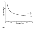
- There are many possible contacts elements arrangement in respect to each other with the double-contact system Vacuum interrupter. The inner part of the double contact is designed for nominal current path thus the contacts resistance should be as low as possible. This is achieved by applying high closing forces to minimize the contact resistance. In general the contact resistance Rc is inversely proportional to the square of the closing forces, i.e. decreases by increasing the closing forces.

- This variation can be illustrated by following
Figure 1 , which shows the change in total impedance of a vacuum interrupter (RT = RB + RC) with Cu-Cr contacts as a function of the contact load. - In case of double-contact electrodes the contact resistance of each contact (inner or outer) can be adjusted by altering the contact forces distribution. This is the basical functional feature of the invention which concerns to the structural features as claimed.
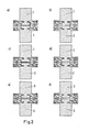
- Like already said above, in order to avoid confusion between the terminology contact and electrode, the electrode is designated to the whole moving or fixed parts. An electrode in this case includes the combination of the inner and the outer contacts. Firstly, the inner and/or outer contacts relative position can be classified according to the following variations, like seen in
figure 2 . - 1.) In the first case only the inner contacts are in touch when the switch is in closed position and the whole nominal current flows through them. They are also used at the initial vacuum arcing phase while performing the current interruption.
- a.) The inner contacts (TMF-like) of both, moving and fixed electrodes, are emerging compared to outer contacts, like shown in
figure 2a . - b.) Alternatively, only one of the inner contacts (the moving or the fixed one) is emerging compared to the outer contact, while the other inner contact is at the same level as the outer contact, see
figure 2b .
While opening, the arc ignites first between the inner contacts, then develops in succeeding modes as the contacts distance increased then commutes partially to the outer contacts after some milliseconds. At this time the outer contacts start to generate AMF field corresponding to the current flow through them. After that the arc takes some other milliseconds to commute to fully diffuse arc as the AMF generation starts with some delay (Note: The delay caused by the phase shift between the B-field (AMF) and the current due to eddy currents effect is not taken into account here; it's found to be negligible in this double-contact structure). - a.) The inner contacts (TMF-like) of both, moving and fixed electrodes, are emerging compared to outer contacts, like shown in
- 2.) In the second case, the gap distance (in open position) between the inner contacts (moving and fixed) and the outer contacts (moving and fixed) is kept the same. Two relative position cases can be distinguished.
- a.) The inner contact of one electrode (moving and fixed) is rising compared to the outer contact, while the position of the inner part of the opposite electrode is lowered (or pushed inwardly); see
figure 2 c. - b.) All inner and outer contacts are at the same level, see
figure 2 d.
case 3. This means that the contact resistance through the inner contacts is much lower than the contact resistance through the outer ones.
While opening, the elastic deformation propriety of the outer contacts ensures the arc ignition between the outer contacts as the last touching point is found between them.
These two features give to this configuration a real big asset, because it has the advantage of the low contact resistance for nominal current (between inner contacts), and the arc ignition between the outer contacts, which are responsible for the AMF field generation. The arc commutation to the fully diffuse arc takes shorter time with this arrangement. - a.) The inner contact of one electrode (moving and fixed) is rising compared to the outer contact, while the position of the inner part of the opposite electrode is lowered (or pushed inwardly); see
- 3.) The third case is the inverse of the first one, i.e. the gap distance between the outer contacts (in open position) is smaller than the gap distance between the inner contacts. However this difference should be as small as 0.1 - 2.5 mm and preferentially 0.5 - 1.5 mm. Here also we can distinguish two cases.
- a.) Both inner contacts are pushed inwardly compared to the outer ones, but with very small distance; see
figure 2 e. - b.) The inner contact of one electrode is pushed inwardly while the other inner contact of the opposite electrode is kept at the same level as the outer contact , see
figure 2 f.
In this case, the arc ignition will start at the outer contact but the contact resistance of the inner contacts (for the nominal current) is increased unless the elastic properties of the outer contacts are changed (to increase the deformation of the outer contact).
It is important to notice that the elasticity of the outer contact can be influenced by the outer contact diameter, the cup thickness and the cup material as well. - a.) Both inner contacts are pushed inwardly compared to the outer ones, but with very small distance; see
- According to another embodiment, the outer contact (cup-shaped) is made from a double or multiple layers in which one layer at least is made from a strong, elastic and conductive material like stainless steel, and at least a second layer made from high thermal conductivity material like copper. This combination offers both robustness and cost effectiveness criteria to the contact assembly and would guarantee a better thermal management during and after arcing (fast contacts cooling).
- The multi-layer cup-shaped contact may have several various arrangements on the superposition order of the layers depending on the intended application. For example for a double-layer:
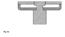
- 1.) The inner layer is made from stainless-steel (hard conductive material) and the outer one from copper (excellent thermal and electrical conductor). In this case the major part of the short circuit current passes through outer layer (copper), thus increasing the effective AMF area. This arrangement is favoured for increased high current interruption performance.
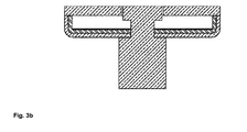
- 2.) The inner layer is made from copper and the outer one from stainless-steel. Here, the outer layer of the cup-shaped contact is made from stainless-steel thus could be considered for withstanding high voltage towards the shield. This arrangement can be a good option for high voltage application. The contacts forces distribution changes slightly by using these two arrangements due to the change in the outer contact elasticity as shown, see for example
figure 3 . The force between the outer contacts decreased from 100 N in case of stainless-steel monolayer to ∼ 70 N by using a double layer. - 3.) Alternatively, the inner layer can be made from stainless-steel and a second layer made from copper; a third very thin layer can be superposed to the second outer layer and made from stainless-steel or another metal with good high voltage withstand properties (Nickel, steel-alloy, etc). This very thin layer can be obtained for example by coating with electroplating, electroforming or PVD processes, etc. With this multilayer structure we increase the effective AMF area during the high current interruption process, and increase the high voltage withstand performance of the vacuum interrupter.
- 4.) Alternatively, an inversed arrangement of the multilayer cup-shape contact is possible. The inner layer is made from copper and the outer layer from stainless-steel (the stainless-steel layer is necessary for contacts robustness). The stainless-steel layer is superposed by a very thin layer of copper which can be obtained by coating with electroplating, electroforming or PVD processes, etc.
- So
figures 3a ,3b ,3c and3d show different the embodiments. -
Figure 3a shows a double layer system with a stainless-steel inner layer and a copper outer layer. -
Figure 3b shows a double layer system with a copper inner layer and a stainless steel outer layer. -
Figure 3c shows a multilayer system with stainless steel inner layer, plus a copper outer layer with a thin coverage by steel/nickel layer. -
Figure 3d shows a multilayer system with a copper inner layer plus a stainless steel outer layer with a thin coverage by a thin copper layer.
Claims (14)
- Vacuum interrupter with double co-axial contacts arrangement in which the inner contact has a TMF-like or Pin shape arranged within concentrically cup shaped AMF coil; with a single layer or multilayered arranged contact parts at each side, th.m. on the side of a fixed contact arrangement as well as on the side of a movable contact arrangement,
characterized in that,
that the outer cup shaped contact is made from a single layer, or double or multiple layer arrangement, wherein at least one layer is made from a hard steel or steel alloy and in case of multilayer arrangement at least a second layer is made from material with high thermal conductivity. - Vacuum interrupter according to claim 1,
characterized in,
that the material of high thermal conductivity is copper, silver, silver-alloy or copper-alloy. - Vacuum interrupter according to claim 1,
characterized in,
that the hard steel or steel alloy is stainless steel. - Vacuum interrupter according to claim 1, 2 or 3,
characterized in,
that the inner layer of the double or multiple layer contact arrangement is made of stainless steel or another material with similar stiffness, and the outer or the second layer is made of copper. - Vacuum interrupter according to claim 1, 2 or 3,
characterized in,
that in case of a cup shaped contact arrangement the inner layer of the contact arrangement is made of copper, and the other or the outer layer is made of stainless steel. - Vacuum interrupter according to one of the aforesaid claims 1 to 4,
characterized in,
that the outer layer is covered or coated with a very thin layer up to 100 µm thickness from high voltage withstand material. - Vacuum interrupter according to claim 6, characterized in,
thin layer material is Nickel, steel or steel alloy. - Vacuum interrupter according to one of the aforesaid claims 1 to 3 and 5,
characterized in,
that the outer layer is covered or coated with a very thin layer up to 100 µm thickness from copper, silver or copper alloy. - Vacuum interrupter according to one of the aforesaid claims 1 to 8,
characterized in,
that the contact parts are positioned like that only the inner contacts are in touch when the vacuum interrupter is in closed position, and the whole nominal current flows through them. - Vacuum interrupter according to one of the aforesaid claims 1 to 8,
characterized in,
that the respective gap distance in open position of the vacuum interrupter between the inner contacts, and between the outer contacts is kept the same. - Vacuum interrupter according to one of the aforesaid claims 1 to 8,
characterized in,
that the gap distance between the outer contacts in opened position of the vacuum interrupter is smaller than the gap distance between the inner contacts. - Vacuum interrupter according to the aforesaid claims 1, 9 to 11,
characterized in,
that in closed position of the vacuum interrupter a totality or a quasi-totality of nominal current flows through the inner contacts. - Vacuum interrupter according to the aforesaid claims 1 and 9,
characterized in,
that while opening (disconnecting) the contacts of the vacuum interrupter during the current interruption process, the arc ignition takes place between the inner contacts, then commutes partially or totally to the outer contacts and transforms to a diffuse arc under the effect of the generated AMF corresponding to the current flow through the outer contacts. - Vacuum interrupter according to the aforesaid claims 1 and 10 to 12,
characterized in,
that while opening (disconnecting) the contacts of the vacuum interrupter during the current interruption process, the arc ignition takes place between the outer contacts, then transforms quickly to a diffuse arc under the effect of the generated AMF corresponding to the current flow through the outer contacts.
Priority Applications (7)
| Application Number | Priority Date | Filing Date | Title |
|---|---|---|---|
| EP20189894.7A EP3754684A1 (en) | 2012-06-11 | 2012-10-18 | Vacuum interrupter with double coaxial contact arrangement at each side |
| EP12007203.8A EP2674955B1 (en) | 2012-06-11 | 2012-10-18 | Vacuum interrupter with double coaxial contact arrangement at each side |
| PCT/EP2013/001708 WO2013185906A1 (en) | 2012-06-11 | 2013-06-11 | Vacuum interrupter with double coaxial contact arrangement at each side |
| IN10567DEN2014 IN2014DN10567A (en) | 2012-06-11 | 2013-06-11 | |
| CN201380038542.1A CN104488057A (en) | 2012-06-11 | 2013-06-11 | Vacuum interrupter with double coaxial contact arrangement at each side |
| JP2015516506A JP2015519713A (en) | 2012-06-11 | 2013-06-11 | Vacuum circuit breaker with double coaxial contact configuration on both sides |
| US14/567,489 US20150114931A1 (en) | 2012-06-11 | 2014-12-11 | Vacuum interrupter with double coaxial contact arrangement at each side |
Applications Claiming Priority (2)
| Application Number | Priority Date | Filing Date | Title |
|---|---|---|---|
| EP12004395 | 2012-06-11 | ||
| EP12007203.8A EP2674955B1 (en) | 2012-06-11 | 2012-10-18 | Vacuum interrupter with double coaxial contact arrangement at each side |
Related Child Applications (2)
| Application Number | Title | Priority Date | Filing Date |
|---|---|---|---|
| EP20189894.7A Division-Into EP3754684A1 (en) | 2012-06-11 | 2012-10-18 | Vacuum interrupter with double coaxial contact arrangement at each side |
| EP20189894.7A Division EP3754684A1 (en) | 2012-06-11 | 2012-10-18 | Vacuum interrupter with double coaxial contact arrangement at each side |
Publications (2)
| Publication Number | Publication Date |
|---|---|
| EP2674955A1 true EP2674955A1 (en) | 2013-12-18 |
| EP2674955B1 EP2674955B1 (en) | 2020-12-02 |
Family
ID=47044725
Family Applications (2)
| Application Number | Title | Priority Date | Filing Date |
|---|---|---|---|
| EP20189894.7A Pending EP3754684A1 (en) | 2012-06-11 | 2012-10-18 | Vacuum interrupter with double coaxial contact arrangement at each side |
| EP12007203.8A Active EP2674955B1 (en) | 2012-06-11 | 2012-10-18 | Vacuum interrupter with double coaxial contact arrangement at each side |
Family Applications Before (1)
| Application Number | Title | Priority Date | Filing Date |
|---|---|---|---|
| EP20189894.7A Pending EP3754684A1 (en) | 2012-06-11 | 2012-10-18 | Vacuum interrupter with double coaxial contact arrangement at each side |
Country Status (6)
| Country | Link |
|---|---|
| US (1) | US20150114931A1 (en) |
| EP (2) | EP3754684A1 (en) |
| JP (1) | JP2015519713A (en) |
| CN (1) | CN104488057A (en) |
| IN (1) | IN2014DN10567A (en) |
| WO (1) | WO2013185906A1 (en) |
Families Citing this family (1)
| Publication number | Priority date | Publication date | Assignee | Title |
|---|---|---|---|---|
| DE102020212377A1 (en) * | 2020-09-30 | 2022-03-31 | Siemens Aktiengesellschaft | Compact vacuum interrupter |
Citations (3)
| Publication number | Priority date | Publication date | Assignee | Title |
|---|---|---|---|---|
| DE9305125U1 (en) * | 1993-03-30 | 1994-08-04 | Siemens AG, 80333 München | Contact arrangement for a vacuum interrupter |
| EP0660353A2 (en) * | 1993-12-24 | 1995-06-28 | Hitachi, Ltd. | Vacuum valve and method of manufacturing the same |
| EP2434513A1 (en) | 2010-09-24 | 2012-03-28 | ABB Technology AG | Electrical contact arrangement for vacuum interrupter arrangement |
Family Cites Families (10)
| Publication number | Priority date | Publication date | Assignee | Title |
|---|---|---|---|---|
| US3210505A (en) * | 1962-04-03 | 1965-10-05 | Gen Electric | Electrode structure for an electric circuit interrupter |
| US3980850A (en) * | 1974-12-19 | 1976-09-14 | Westinghouse Electric Corporation | Vacuum interrupter with cup-shaped contact having an inner arc controlling electrode |
| JPS56138836A (en) * | 1980-03-31 | 1981-10-29 | Meidensha Electric Mfg Co Ltd | Vacuum breaker |
| JPS6065413A (en) * | 1983-09-20 | 1985-04-15 | 株式会社東芝 | Vacuum breaker |
| US4847456A (en) * | 1987-09-23 | 1989-07-11 | Westinghouse Electric Corp. | Vacuum circuit interrupter with axial magnetic arc transfer mechanism |
| DE10221363C1 (en) * | 2002-05-07 | 2003-12-24 | Siemens Ag | Pot-shaped switch contact with metal vapor shield |
| US6965089B2 (en) * | 2003-02-21 | 2005-11-15 | Mcgraw-Edison Company | Axial magnetic field vacuum fault interrupter |
| CN1981354B (en) * | 2004-07-05 | 2011-10-26 | Abb研究有限公司 | Vacuum interrupter and contact arrangement for a vacuum interrupter |
| CN101164130A (en) * | 2005-04-16 | 2008-04-16 | Abb技术股份公司 | Manufacturing method of contact piece for vacuum switch box |
| DE102006042101B4 (en) * | 2006-09-07 | 2008-09-25 | Switchcraft Europe Gmbh | Vacuum switch for medium and high voltages |
-
2012
- 2012-10-18 EP EP20189894.7A patent/EP3754684A1/en active Pending
- 2012-10-18 EP EP12007203.8A patent/EP2674955B1/en active Active
-
2013
- 2013-06-11 CN CN201380038542.1A patent/CN104488057A/en active Pending
- 2013-06-11 IN IN10567DEN2014 patent/IN2014DN10567A/en unknown
- 2013-06-11 WO PCT/EP2013/001708 patent/WO2013185906A1/en not_active Ceased
- 2013-06-11 JP JP2015516506A patent/JP2015519713A/en active Pending
-
2014
- 2014-12-11 US US14/567,489 patent/US20150114931A1/en not_active Abandoned
Patent Citations (3)
| Publication number | Priority date | Publication date | Assignee | Title |
|---|---|---|---|---|
| DE9305125U1 (en) * | 1993-03-30 | 1994-08-04 | Siemens AG, 80333 München | Contact arrangement for a vacuum interrupter |
| EP0660353A2 (en) * | 1993-12-24 | 1995-06-28 | Hitachi, Ltd. | Vacuum valve and method of manufacturing the same |
| EP2434513A1 (en) | 2010-09-24 | 2012-03-28 | ABB Technology AG | Electrical contact arrangement for vacuum interrupter arrangement |
Also Published As
| Publication number | Publication date |
|---|---|
| WO2013185906A1 (en) | 2013-12-19 |
| CN104488057A (en) | 2015-04-01 |
| EP2674955B1 (en) | 2020-12-02 |
| US20150114931A1 (en) | 2015-04-30 |
| IN2014DN10567A (en) | 2015-08-28 |
| EP3754684A1 (en) | 2020-12-23 |
| JP2015519713A (en) | 2015-07-09 |
Similar Documents
| Publication | Publication Date | Title |
|---|---|---|
| EP2434513B1 (en) | Electrical contact arrangement for vacuum interrupter arrangement | |
| EP2551878A1 (en) | Contact assembly for a vacuum circuit breaker | |
| CN101459013B (en) | Longitudinal magnetic field electrode vacuum switch tube with low loop resistance | |
| US4594489A (en) | Electrical switching element | |
| US20220013307A1 (en) | Dual parallel moveable electrical contacts/relays | |
| US9202645B2 (en) | Switchgear for a vacuum circuit breaker comprising locking means | |
| EP2674955A1 (en) | Vacuum interrupter with double coaxial contact arrangement at each side | |
| US20240087822A1 (en) | Vacuum Interrupter | |
| US9837232B2 (en) | Electromechanical circuit breaker | |
| CN102034640B (en) | There is the power switch in rated current path in parallel | |
| KR101015495B1 (en) | On-load tap-changer for sequence switch | |
| US20080121504A1 (en) | Electrical contact system for an electrical switching device | |
| CN104362054A (en) | Combined type auxiliary switch used for circuit breaker mechanism | |
| EP3926654B1 (en) | Circuit breaker with field deflection element | |
| JP2018181681A (en) | Shrinkage ring and vacuum interrupter | |
| JP2002505797A (en) | Arc switching switch | |
| CN1902721B (en) | Electrical contact for medium or high voltage electrical equipment, method and apparatus for making same | |
| JP5525316B2 (en) | Vacuum valve | |
| US20190066949A1 (en) | Heavy current reed switch contact structure | |
| US3996438A (en) | Vacuum-type circuit interrupter with two sets of contacts electrically in parallel | |
| KR20160040585A (en) | Electric contact point and contact element | |
| CN215377239U (en) | Contact for a medium-voltage or high-voltage circuit breaker and medium-voltage or high-voltage circuit breaker | |
| JP2013222528A (en) | Vacuum switch | |
| FR2985080A1 (en) | Electric connection assembly for use in e.g. high voltage circuit breaker, has cylindrical electrically conducting part comprising switching finger exceeding main contact finger at distance not to contact switching finger | |
| US20180174770A1 (en) | Electrical contact material |
Legal Events
| Date | Code | Title | Description |
|---|---|---|---|
| PUAI | Public reference made under article 153(3) epc to a published international application that has entered the european phase |
Free format text: ORIGINAL CODE: 0009012 |
|
| AK | Designated contracting states |
Kind code of ref document: A1 Designated state(s): AL AT BE BG CH CY CZ DE DK EE ES FI FR GB GR HR HU IE IS IT LI LT LU LV MC MK MT NL NO PL PT RO RS SE SI SK SM TR |
|
| AX | Request for extension of the european patent |
Extension state: BA ME |
|
| 17P | Request for examination filed |
Effective date: 20140528 |
|
| RBV | Designated contracting states (corrected) |
Designated state(s): AL AT BE BG CH CY CZ DE DK EE ES FI FR GB GR HR HU IE IS IT LI LT LU LV MC MK MT NL NO PL PT RO RS SE SI SK SM TR |
|
| 17Q | First examination report despatched |
Effective date: 20160905 |
|
| RAP1 | Party data changed (applicant data changed or rights of an application transferred) |
Owner name: ABB SCHWEIZ AG |
|
| STAA | Information on the status of an ep patent application or granted ep patent |
Free format text: STATUS: EXAMINATION IS IN PROGRESS |
|
| GRAP | Despatch of communication of intention to grant a patent |
Free format text: ORIGINAL CODE: EPIDOSNIGR1 |
|
| STAA | Information on the status of an ep patent application or granted ep patent |
Free format text: STATUS: GRANT OF PATENT IS INTENDED |
|
| INTG | Intention to grant announced |
Effective date: 20200520 |
|
| GRAS | Grant fee paid |
Free format text: ORIGINAL CODE: EPIDOSNIGR3 |
|
| RAP1 | Party data changed (applicant data changed or rights of an application transferred) |
Owner name: ABB SCHWEIZ AG |
|
| RIN1 | Information on inventor provided before grant (corrected) |
Inventor name: LAMARA, TAREK Inventor name: SOKOLOV, ALEXEY Inventor name: GENTSCH, DIETMAR |
|
| GRAA | (expected) grant |
Free format text: ORIGINAL CODE: 0009210 |
|
| STAA | Information on the status of an ep patent application or granted ep patent |
Free format text: STATUS: THE PATENT HAS BEEN GRANTED |
|
| AK | Designated contracting states |
Kind code of ref document: B1 Designated state(s): AL AT BE BG CH CY CZ DE DK EE ES FI FR GB GR HR HU IE IS IT LI LT LU LV MC MK MT NL NO PL PT RO RS SE SI SK SM TR |
|
| REG | Reference to a national code |
Ref country code: GB Ref legal event code: FG4D |
|
| REG | Reference to a national code |
Ref country code: AT Ref legal event code: REF Ref document number: 1341831 Country of ref document: AT Kind code of ref document: T Effective date: 20201215 Ref country code: CH Ref legal event code: EP |
|
| REG | Reference to a national code |
Ref country code: IE Ref legal event code: FG4D |
|
| REG | Reference to a national code |
Ref country code: DE Ref legal event code: R096 Ref document number: 602012073465 Country of ref document: DE |
|
| PG25 | Lapsed in a contracting state [announced via postgrant information from national office to epo] |
Ref country code: GR Free format text: LAPSE BECAUSE OF FAILURE TO SUBMIT A TRANSLATION OF THE DESCRIPTION OR TO PAY THE FEE WITHIN THE PRESCRIBED TIME-LIMIT Effective date: 20210303 Ref country code: FI Free format text: LAPSE BECAUSE OF FAILURE TO SUBMIT A TRANSLATION OF THE DESCRIPTION OR TO PAY THE FEE WITHIN THE PRESCRIBED TIME-LIMIT Effective date: 20201202 Ref country code: RS Free format text: LAPSE BECAUSE OF FAILURE TO SUBMIT A TRANSLATION OF THE DESCRIPTION OR TO PAY THE FEE WITHIN THE PRESCRIBED TIME-LIMIT Effective date: 20201202 Ref country code: NO Free format text: LAPSE BECAUSE OF FAILURE TO SUBMIT A TRANSLATION OF THE DESCRIPTION OR TO PAY THE FEE WITHIN THE PRESCRIBED TIME-LIMIT Effective date: 20210302 |
|
| REG | Reference to a national code |
Ref country code: NL Ref legal event code: MP Effective date: 20201202 |
|
| REG | Reference to a national code |
Ref country code: AT Ref legal event code: MK05 Ref document number: 1341831 Country of ref document: AT Kind code of ref document: T Effective date: 20201202 |
|
| PG25 | Lapsed in a contracting state [announced via postgrant information from national office to epo] |
Ref country code: LV Free format text: LAPSE BECAUSE OF FAILURE TO SUBMIT A TRANSLATION OF THE DESCRIPTION OR TO PAY THE FEE WITHIN THE PRESCRIBED TIME-LIMIT Effective date: 20201202 Ref country code: SE Free format text: LAPSE BECAUSE OF FAILURE TO SUBMIT A TRANSLATION OF THE DESCRIPTION OR TO PAY THE FEE WITHIN THE PRESCRIBED TIME-LIMIT Effective date: 20201202 Ref country code: PL Free format text: LAPSE BECAUSE OF FAILURE TO SUBMIT A TRANSLATION OF THE DESCRIPTION OR TO PAY THE FEE WITHIN THE PRESCRIBED TIME-LIMIT Effective date: 20201202 Ref country code: BG Free format text: LAPSE BECAUSE OF FAILURE TO SUBMIT A TRANSLATION OF THE DESCRIPTION OR TO PAY THE FEE WITHIN THE PRESCRIBED TIME-LIMIT Effective date: 20210302 |
|
| PG25 | Lapsed in a contracting state [announced via postgrant information from national office to epo] |
Ref country code: NL Free format text: LAPSE BECAUSE OF FAILURE TO SUBMIT A TRANSLATION OF THE DESCRIPTION OR TO PAY THE FEE WITHIN THE PRESCRIBED TIME-LIMIT Effective date: 20201202 Ref country code: HR Free format text: LAPSE BECAUSE OF FAILURE TO SUBMIT A TRANSLATION OF THE DESCRIPTION OR TO PAY THE FEE WITHIN THE PRESCRIBED TIME-LIMIT Effective date: 20201202 |
|
| REG | Reference to a national code |
Ref country code: LT Ref legal event code: MG9D |
|
| PG25 | Lapsed in a contracting state [announced via postgrant information from national office to epo] |
Ref country code: LT Free format text: LAPSE BECAUSE OF FAILURE TO SUBMIT A TRANSLATION OF THE DESCRIPTION OR TO PAY THE FEE WITHIN THE PRESCRIBED TIME-LIMIT Effective date: 20201202 Ref country code: PT Free format text: LAPSE BECAUSE OF FAILURE TO SUBMIT A TRANSLATION OF THE DESCRIPTION OR TO PAY THE FEE WITHIN THE PRESCRIBED TIME-LIMIT Effective date: 20210405 Ref country code: SK Free format text: LAPSE BECAUSE OF FAILURE TO SUBMIT A TRANSLATION OF THE DESCRIPTION OR TO PAY THE FEE WITHIN THE PRESCRIBED TIME-LIMIT Effective date: 20201202 Ref country code: RO Free format text: LAPSE BECAUSE OF FAILURE TO SUBMIT A TRANSLATION OF THE DESCRIPTION OR TO PAY THE FEE WITHIN THE PRESCRIBED TIME-LIMIT Effective date: 20201202 Ref country code: SM Free format text: LAPSE BECAUSE OF FAILURE TO SUBMIT A TRANSLATION OF THE DESCRIPTION OR TO PAY THE FEE WITHIN THE PRESCRIBED TIME-LIMIT Effective date: 20201202 Ref country code: EE Free format text: LAPSE BECAUSE OF FAILURE TO SUBMIT A TRANSLATION OF THE DESCRIPTION OR TO PAY THE FEE WITHIN THE PRESCRIBED TIME-LIMIT Effective date: 20201202 Ref country code: CZ Free format text: LAPSE BECAUSE OF FAILURE TO SUBMIT A TRANSLATION OF THE DESCRIPTION OR TO PAY THE FEE WITHIN THE PRESCRIBED TIME-LIMIT Effective date: 20201202 |
|
| PG25 | Lapsed in a contracting state [announced via postgrant information from national office to epo] |
Ref country code: AT Free format text: LAPSE BECAUSE OF FAILURE TO SUBMIT A TRANSLATION OF THE DESCRIPTION OR TO PAY THE FEE WITHIN THE PRESCRIBED TIME-LIMIT Effective date: 20201202 |
|
| REG | Reference to a national code |
Ref country code: DE Ref legal event code: R097 Ref document number: 602012073465 Country of ref document: DE |
|
| PG25 | Lapsed in a contracting state [announced via postgrant information from national office to epo] |
Ref country code: IS Free format text: LAPSE BECAUSE OF FAILURE TO SUBMIT A TRANSLATION OF THE DESCRIPTION OR TO PAY THE FEE WITHIN THE PRESCRIBED TIME-LIMIT Effective date: 20210402 |
|
| PLBE | No opposition filed within time limit |
Free format text: ORIGINAL CODE: 0009261 |
|
| STAA | Information on the status of an ep patent application or granted ep patent |
Free format text: STATUS: NO OPPOSITION FILED WITHIN TIME LIMIT |
|
| PG25 | Lapsed in a contracting state [announced via postgrant information from national office to epo] |
Ref country code: IT Free format text: LAPSE BECAUSE OF FAILURE TO SUBMIT A TRANSLATION OF THE DESCRIPTION OR TO PAY THE FEE WITHIN THE PRESCRIBED TIME-LIMIT Effective date: 20201202 Ref country code: AL Free format text: LAPSE BECAUSE OF FAILURE TO SUBMIT A TRANSLATION OF THE DESCRIPTION OR TO PAY THE FEE WITHIN THE PRESCRIBED TIME-LIMIT Effective date: 20201202 |
|
| 26N | No opposition filed |
Effective date: 20210903 |
|
| PG25 | Lapsed in a contracting state [announced via postgrant information from national office to epo] |
Ref country code: SI Free format text: LAPSE BECAUSE OF FAILURE TO SUBMIT A TRANSLATION OF THE DESCRIPTION OR TO PAY THE FEE WITHIN THE PRESCRIBED TIME-LIMIT Effective date: 20201202 Ref country code: ES Free format text: LAPSE BECAUSE OF FAILURE TO SUBMIT A TRANSLATION OF THE DESCRIPTION OR TO PAY THE FEE WITHIN THE PRESCRIBED TIME-LIMIT Effective date: 20201202 Ref country code: DK Free format text: LAPSE BECAUSE OF FAILURE TO SUBMIT A TRANSLATION OF THE DESCRIPTION OR TO PAY THE FEE WITHIN THE PRESCRIBED TIME-LIMIT Effective date: 20201202 |
|
| PG25 | Lapsed in a contracting state [announced via postgrant information from national office to epo] |
Ref country code: IS Free format text: LAPSE BECAUSE OF FAILURE TO SUBMIT A TRANSLATION OF THE DESCRIPTION OR TO PAY THE FEE WITHIN THE PRESCRIBED TIME-LIMIT Effective date: 20210402 |
|
| REG | Reference to a national code |
Ref country code: CH Ref legal event code: PL |
|
| REG | Reference to a national code |
Ref country code: BE Ref legal event code: MM Effective date: 20211031 |
|
| GBPC | Gb: european patent ceased through non-payment of renewal fee |
Effective date: 20211018 |
|
| PG25 | Lapsed in a contracting state [announced via postgrant information from national office to epo] |
Ref country code: MC Free format text: LAPSE BECAUSE OF FAILURE TO SUBMIT A TRANSLATION OF THE DESCRIPTION OR TO PAY THE FEE WITHIN THE PRESCRIBED TIME-LIMIT Effective date: 20201202 |
|
| PG25 | Lapsed in a contracting state [announced via postgrant information from national office to epo] |
Ref country code: LU Free format text: LAPSE BECAUSE OF NON-PAYMENT OF DUE FEES Effective date: 20211018 Ref country code: GB Free format text: LAPSE BECAUSE OF NON-PAYMENT OF DUE FEES Effective date: 20211018 Ref country code: BE Free format text: LAPSE BECAUSE OF NON-PAYMENT OF DUE FEES Effective date: 20211031 |
|
| PG25 | Lapsed in a contracting state [announced via postgrant information from national office to epo] |
Ref country code: LI Free format text: LAPSE BECAUSE OF NON-PAYMENT OF DUE FEES Effective date: 20211031 Ref country code: CH Free format text: LAPSE BECAUSE OF NON-PAYMENT OF DUE FEES Effective date: 20211031 |
|
| PG25 | Lapsed in a contracting state [announced via postgrant information from national office to epo] |
Ref country code: IE Free format text: LAPSE BECAUSE OF NON-PAYMENT OF DUE FEES Effective date: 20211018 |
|
| PG25 | Lapsed in a contracting state [announced via postgrant information from national office to epo] |
Ref country code: HU Free format text: LAPSE BECAUSE OF FAILURE TO SUBMIT A TRANSLATION OF THE DESCRIPTION OR TO PAY THE FEE WITHIN THE PRESCRIBED TIME-LIMIT; INVALID AB INITIO Effective date: 20121018 Ref country code: CY Free format text: LAPSE BECAUSE OF FAILURE TO SUBMIT A TRANSLATION OF THE DESCRIPTION OR TO PAY THE FEE WITHIN THE PRESCRIBED TIME-LIMIT Effective date: 20201202 |
|
| PG25 | Lapsed in a contracting state [announced via postgrant information from national office to epo] |
Ref country code: MK Free format text: LAPSE BECAUSE OF FAILURE TO SUBMIT A TRANSLATION OF THE DESCRIPTION OR TO PAY THE FEE WITHIN THE PRESCRIBED TIME-LIMIT Effective date: 20201202 |
|
| PG25 | Lapsed in a contracting state [announced via postgrant information from national office to epo] |
Ref country code: TR Free format text: LAPSE BECAUSE OF FAILURE TO SUBMIT A TRANSLATION OF THE DESCRIPTION OR TO PAY THE FEE WITHIN THE PRESCRIBED TIME-LIMIT Effective date: 20201202 |
|
| PG25 | Lapsed in a contracting state [announced via postgrant information from national office to epo] |
Ref country code: MT Free format text: LAPSE BECAUSE OF FAILURE TO SUBMIT A TRANSLATION OF THE DESCRIPTION OR TO PAY THE FEE WITHIN THE PRESCRIBED TIME-LIMIT Effective date: 20201202 |
|
| PGFP | Annual fee paid to national office [announced via postgrant information from national office to epo] |
Ref country code: DE Payment date: 20241021 Year of fee payment: 13 |
|
| PGFP | Annual fee paid to national office [announced via postgrant information from national office to epo] |
Ref country code: FR Payment date: 20241021 Year of fee payment: 13 |