JP2015519713A - Vacuum circuit breaker with double coaxial contact configuration on both sides - Google Patents
Vacuum circuit breaker with double coaxial contact configuration on both sides Download PDFInfo
- Publication number
- JP2015519713A JP2015519713A JP2015516506A JP2015516506A JP2015519713A JP 2015519713 A JP2015519713 A JP 2015519713A JP 2015516506 A JP2015516506 A JP 2015516506A JP 2015516506 A JP2015516506 A JP 2015516506A JP 2015519713 A JP2015519713 A JP 2015519713A
- Authority
- JP
- Japan
- Prior art keywords
- contact
- circuit breaker
- vacuum circuit
- layer
- contacts
- Prior art date
- Legal status (The legal status is an assumption and is not a legal conclusion. Google has not performed a legal analysis and makes no representation as to the accuracy of the status listed.)
- Pending
Links
- 239000010410 layer Substances 0.000 claims abstract description 63
- 239000000463 material Substances 0.000 claims abstract description 13
- 229910000831 Steel Inorganic materials 0.000 claims abstract description 8
- 239000010959 steel Substances 0.000 claims abstract description 8
- 239000002356 single layer Substances 0.000 claims abstract description 5
- 239000010935 stainless steel Substances 0.000 claims description 22
- 229910001220 stainless steel Inorganic materials 0.000 claims description 22
- RYGMFSIKBFXOCR-UHFFFAOYSA-N Copper Chemical group [Cu] RYGMFSIKBFXOCR-UHFFFAOYSA-N 0.000 claims description 21
- 229910052802 copper Inorganic materials 0.000 claims description 21
- 239000010949 copper Substances 0.000 claims description 21
- 229910000851 Alloy steel Inorganic materials 0.000 claims description 6
- PXHVJJICTQNCMI-UHFFFAOYSA-N Nickel Chemical group [Ni] PXHVJJICTQNCMI-UHFFFAOYSA-N 0.000 claims description 6
- 238000000034 method Methods 0.000 claims description 5
- 229910052759 nickel Inorganic materials 0.000 claims description 3
- 238000009792 diffusion process Methods 0.000 claims description 2
- 229910001316 Ag alloy Inorganic materials 0.000 claims 2
- 229910000881 Cu alloy Inorganic materials 0.000 claims 2
- BQCADISMDOOEFD-UHFFFAOYSA-N Silver Chemical compound [Ag] BQCADISMDOOEFD-UHFFFAOYSA-N 0.000 claims 2
- 239000004332 silver Substances 0.000 claims 2
- 229910052709 silver Inorganic materials 0.000 claims 1
- 239000000956 alloy Substances 0.000 abstract 1
- 229910045601 alloy Inorganic materials 0.000 abstract 1
- 239000004020 conductor Substances 0.000 description 6
- 230000000717 retained effect Effects 0.000 description 3
- 239000011248 coating agent Substances 0.000 description 2
- 238000000576 coating method Methods 0.000 description 2
- 230000005489 elastic deformation Effects 0.000 description 2
- 238000005323 electroforming Methods 0.000 description 2
- 238000009713 electroplating Methods 0.000 description 2
- 238000005240 physical vapour deposition Methods 0.000 description 2
- 238000001816 cooling Methods 0.000 description 1
- 230000007423 decrease Effects 0.000 description 1
- 230000009977 dual effect Effects 0.000 description 1
- 230000000694 effects Effects 0.000 description 1
- 239000002184 metal Substances 0.000 description 1
- 229910052751 metal Inorganic materials 0.000 description 1
- 239000002470 thermal conductor Substances 0.000 description 1
Images
Classifications
-
- H—ELECTRICITY
- H01—ELECTRIC ELEMENTS
- H01H—ELECTRIC SWITCHES; RELAYS; SELECTORS; EMERGENCY PROTECTIVE DEVICES
- H01H33/00—High-tension or heavy-current switches with arc-extinguishing or arc-preventing means
- H01H33/60—Switches wherein the means for extinguishing or preventing the arc do not include separate means for obtaining or increasing flow of arc-extinguishing fluid
- H01H33/66—Vacuum switches
- H01H33/6606—Terminal arrangements
-
- H—ELECTRICITY
- H01—ELECTRIC ELEMENTS
- H01H—ELECTRIC SWITCHES; RELAYS; SELECTORS; EMERGENCY PROTECTIVE DEVICES
- H01H33/00—High-tension or heavy-current switches with arc-extinguishing or arc-preventing means
- H01H33/60—Switches wherein the means for extinguishing or preventing the arc do not include separate means for obtaining or increasing flow of arc-extinguishing fluid
- H01H33/66—Vacuum switches
- H01H33/664—Contacts; Arc-extinguishing means, e.g. arcing rings
- H01H33/6642—Contacts; Arc-extinguishing means, e.g. arcing rings having cup-shaped contacts, the cylindrical wall of which being provided with inclined slits to form a coil
-
- H—ELECTRICITY
- H01—ELECTRIC ELEMENTS
- H01H—ELECTRIC SWITCHES; RELAYS; SELECTORS; EMERGENCY PROTECTIVE DEVICES
- H01H33/00—High-tension or heavy-current switches with arc-extinguishing or arc-preventing means
- H01H33/60—Switches wherein the means for extinguishing or preventing the arc do not include separate means for obtaining or increasing flow of arc-extinguishing fluid
- H01H33/66—Vacuum switches
- H01H33/664—Contacts; Arc-extinguishing means, e.g. arcing rings
- H01H33/6643—Contacts; Arc-extinguishing means, e.g. arcing rings having disc-shaped contacts subdivided in petal-like segments, e.g. by helical grooves
-
- H—ELECTRICITY
- H01—ELECTRIC ELEMENTS
- H01H—ELECTRIC SWITCHES; RELAYS; SELECTORS; EMERGENCY PROTECTIVE DEVICES
- H01H2201/00—Contacts
- H01H2201/022—Material
- H01H2201/03—Composite
-
- H—ELECTRICITY
- H01—ELECTRIC ELEMENTS
- H01H—ELECTRIC SWITCHES; RELAYS; SELECTORS; EMERGENCY PROTECTIVE DEVICES
- H01H2203/00—Form of contacts
Landscapes
- Contacts (AREA)
- High-Tension Arc-Extinguishing Switches Without Spraying Means (AREA)
Abstract
本発明は、二重同軸コンタクト構成を有する真空遮断器に関するものであり、請求項1のプリアンブルに記載されているように、内側コンタクトは、同心のカップ形状のAMFコイル内に配置されるTMFのような形状またはピン形状を有し、両側に、すなわち、固定コンタクトの配置側および移動コンタクト配置側に、単層または多層のコンタクト部品を有する。この特別な構造をさらに強化し、高伝導および低抵抗を達成するために、本発明では、カップ形状の外側コンタクトは、二重層または多層の構成から成り、少なくとも1つの層は、硬鋼または合金鋼から成り、少なくとも第2の層は、高熱伝導性を有する材料から成る。The present invention relates to a vacuum circuit breaker having a double coaxial contact configuration, and as described in the preamble of claim 1, the inner contact is a TMF disposed in a concentric cup-shaped AMF coil. Such a shape or pin shape is provided, and single-layer or multilayer contact parts are provided on both sides, that is, on the fixed contact arrangement side and the moving contact arrangement side. In order to further strengthen this special structure and achieve high conductivity and low resistance, in the present invention, the cup-shaped outer contact consists of a double-layer or multi-layer configuration, at least one layer being a hard steel or alloy Made of steel, at least the second layer is made of a material having high thermal conductivity.
Description
本発明は、請求項1のプリアンブルに記載されているように、両側に、すなわち、固定コンタクト配置側および移動コンタクト配置側に、同心に配置されたコンタクト部品内に二重コンタクト構成を有する真空遮断器に関するものである。
The present invention as described in the preamble of
高い電流遮断のために設計され、かつ、費用効果的な真空遮断器である二重コンタクト真空遮断器の多数の特徴に対して、一定の改善がなされてきた。二重コンタクト・アセンブリの最も魅力的な特徴は、公称電流を伝導する要素(すなわち、内側コンタクト)と、電流を遮断する要素(すなわち、外側コンタクト)と、の間の別個の機能である。このように、各要素は、その最適形状になるように別個に設計され、最適材料から製造可能である。 Certain improvements have been made to the many features of double contact vacuum circuit breakers that are designed for high current interruptions and are cost effective vacuum circuit breakers. The most attractive feature of the dual contact assembly is the distinct function between the element that conducts the nominal current (ie, the inner contact) and the element that blocks the current (ie, the outer contact). In this way, each element is separately designed to be in its optimal shape and can be manufactured from the optimal material.
この種の二重コンタクト構成は、EP2434513A1から公知である。内側コンタクトは、公称電流を伝導する機能を有するので、非常に小さい全抵抗(接触抵抗および体抵抗)を有さなければならない。このために、内側コンタクトは、TMFのようなコンタクト、または、接合コンタクトであり、銅またはCuCrのような高導電性材料から成る。内側コンタクトは、従来技術の説明に従い、外側コンタクトに対する整流(commutation)前にアークの最初のフェーズを保持する。 A double contact configuration of this kind is known from EP 2434513 A1. Since the inner contact has the function of conducting a nominal current, it must have a very small total resistance (contact resistance and body resistance). For this purpose, the inner contact is a contact such as TMF or a junction contact and is made of a highly conductive material such as copper or CuCr. The inner contact retains the first phase of the arc prior to commutation with respect to the outer contact, as described in the prior art.
外側コンタクトは、AMFを生成する機能のみを有するので、ステンレス鋼のような硬い導電材料から成るカップ形状の薄層を有するように設計されうる。このオプションは、従来のAMFコンタクトに勝る多くの利点を提供し、低い材料コストおよび非常にロバストなコンタクト・アセンブリを提供する。これらの利点は、以下の通りである。
1.高い機械的強度
2.低コストの材料(銅またはCuCrの代わりにステンレス鋼)
3.低い接触量(contacts mass)、コンタクトを駆動する開放力の減少
4.より大きい拡散真空アーク分布に至る大きい有効なAMF領域
Since the outer contact only has the function of generating AMF, it can be designed with a cup-shaped thin layer of a hard conductive material such as stainless steel. This option offers many advantages over traditional AMF contacts, providing low material costs and a very robust contact assembly. These advantages are as follows.
1. 1. High mechanical strength Low cost material (stainless steel instead of copper or CuCr)
3. 3. Low contact mass and reduced opening force that drives the contacts. Large effective AMF region leading to larger diffuse vacuum arc distribution
それゆえ、本発明の目的は、この特別な構造をさらに強化し、高伝導および低抵抗を達成することにある。 The object of the present invention is therefore to further strengthen this special structure to achieve high conductivity and low resistance.
本発明では、カップ形状の外側コンタクトは単層、二重層または多層の構成から成り、少なくとも1つの層は、硬鋼または合金鋼から成り、多層構成の場合には、少なくとも第2の層は、高熱伝導性を有する材料から成る。 In the present invention, the cup-shaped outer contact is composed of a single layer, a double layer or a multilayer structure, at least one layer is composed of hard steel or alloy steel, and in the case of the multilayer structure, at least the second layer is It is made of a material having high thermal conductivity.
有利には、高熱伝導性を有する材料は、銅である。 Advantageously, the material with high thermal conductivity is copper.
さらに有利な実施形態では、硬鋼または合金鋼は、ステンレス鋼である。 In a further advantageous embodiment, the hard steel or alloy steel is stainless steel.
さらに有利な実施形態では、二重または多層のコンタクト構成の内側層はステンレス鋼または同一の剛性を有する他の材料から成り、外側層は銅から成る。 In a further advantageous embodiment, the inner layer of the double or multilayer contact arrangement consists of stainless steel or other material of the same rigidity and the outer layer consists of copper.
さらに有利な実施形態では、カップ形状のコンタクト構成の場合、コンタクト構成の内側層は、銅およびその他から成り、または、カップ形状の配置の場合、外側層は、ステンレス鋼から成る。 In a further advantageous embodiment, in the case of a cup-shaped contact configuration, the inner layer of the contact configuration consists of copper and others, or in the case of a cup-shaped arrangement, the outer layer consists of stainless steel.
さらに有利な実施形態では、真空遮断器が閉鎖位置にあるとき、内側コンタクトのみが接触し、公称電流全体が内側コンタクト内を流れるように、コンタクト部品は配置される。 In a further advantageous embodiment, the contact components are arranged such that when the vacuum circuit breaker is in the closed position, only the inner contact is in contact and the entire nominal current flows in the inner contact.
さらなる実施形態では、真空遮断器の開放位置では、内側コンタクト間および外側コンタクト間の間隔距離は、同一に保たれる。しかし、閉鎖位置では、公称電流の略全体が、内側コンタクト内を流れる。 In a further embodiment, the distance between the inner and outer contacts is kept the same in the open position of the vacuum circuit breaker. However, in the closed position, substantially the entire nominal current flows in the inner contact.
最後の有利な実施形態では、真空遮断器の開放位置では、外側コンタクトの間の間隔距離は、内側コンタクト間の間隔距離より小さい。しかし、閉鎖位置では、公称電流の大部分は、内側コンタクト内を流れる。 In a last advantageous embodiment, in the open position of the vacuum circuit breaker, the distance between the outer contacts is smaller than the distance between the inner contacts. However, in the closed position, the majority of the nominal current flows in the inner contact.
コンタクトという用語と電極という用語の混同を回避するために、電極は、移動部品または固定部品の全体を指す。この場合、電極は、内側コンタクトおよび外側コンタクトの組み合わせを含む。はじめに、内側コンタクトおよび/または外側コンタクトの相対位置は、以下のバリエーションに従って分類可能である。 In order to avoid confusion between the term contact and the term electrode, electrode refers to the entire moving or stationary part. In this case, the electrode includes a combination of inner and outer contacts. First, the relative positions of the inner and / or outer contacts can be classified according to the following variations.
これを実現する詳細な説明は以下に示される。 A detailed description of achieving this is given below.
二重コンタクトシステムの真空遮断器について、互いに接触するコンタクト要素の多数の構成が存在する。二重コンタクトの内側部品は、公称電流経路のために設計されるので、接触抵抗は、できるだけ低くなければならない。これは、接触抵抗を最小化するための高い閉鎖力(closing force)を適用することによって達成される。一般に、接触抵抗RCは、閉鎖力の平方根に反比例する、すなわち、閉鎖力を増加させると減少する。
この関係は、図1に例示され、図1は、CuCrコンタクトを有する真空遮断器の総インピーダンス(RT=RB+RC)の変化をコンタクト負荷の関数として示す。 This relationship is illustrated in FIG. 1, which shows the change in the total impedance (R T = R B + R C ) of a vacuum circuit breaker with CuCr contacts as a function of contact load.
二重のコンタクト電極の場合、各コンタクト(内側または外側)の接触抵抗は、接触力分布を変えることによって調整可能である。これは、請求項に記載される構造的特徴に関する、本発明の基本的な機能的特徴である。 In the case of double contact electrodes, the contact resistance of each contact (inner or outer) can be adjusted by changing the contact force distribution. This is a basic functional feature of the invention with respect to the structural features recited in the claims.
上述したように、コンタクトという用語と電極という用語の混同を回避するために、電極は、移動部品または固定部品の全体を指す。この場合、電極は、内側コンタクトおよび外側コンタクトの組み合わせを含む。はじめに、図2に示すように、内側コンタクトおよび/または外側コンタクトの相対位置は、以下のバリエーションに従って分類可能である。 As mentioned above, to avoid confusion between the term contact and the term electrode, an electrode refers to the entire moving or stationary part. In this case, the electrode includes a combination of inner and outer contacts. First, as shown in FIG. 2, the relative positions of the inner and / or outer contacts can be classified according to the following variations.
1)第1のケースでは、スイッチが閉鎖位置にあるとき、内側コンタクトのみが接触し、公称電流全体は、内側コンタクト内を流れる。内側コンタクトは、最初の真空アーク・フェーズにおいても、電流遮断を実行する。 1) In the first case, when the switch is in the closed position, only the inner contact contacts, and the entire nominal current flows in the inner contact. The inner contact performs a current interruption even in the first vacuum arc phase.
a)図2aに示すように、移動電極および固定電極の両方の内側コンタクト(TMFのような)は、外側コンタクトと比較して表面から突出している。 a) As shown in FIG. 2a, the inner contact (such as TMF) of both the moving electrode and the fixed electrode protrudes from the surface compared to the outer contact.
b)あるいは、図2bに示すように、(移動または固定の)内側コンタクトの一方のみが、外側コンタクトと比較して表面から突出し、内側コンタクトの他方は、外側コンタクトと同一レベルにある。 b) Alternatively, as shown in FIG. 2b, only one of the inner contacts (moving or stationary) protrudes from the surface compared to the outer contact, the other of the inner contacts being at the same level as the outer contact.
この場合、閉鎖位置における合力は、内側コンタクトによって保持される。これは、公称電流全体が内側コンタクト内を流れることを意味する。 In this case, the resultant force in the closed position is held by the inner contact. This means that the entire nominal current flows in the inner contact.
開放時に、最初、アークは内側コンタクト間で点火し、その後、コンタクト距離が増加すると次のモードに発展し、数ミリ秒後に外側コンタクトに部分的に伝わる。この時点で、外側コンタクトは、外側コンタクトを通る電流に対応するAMFの生成を開始する。その後、AMFの生成が若干遅延して開始するので、アークは、数ミリ秒間発生し、拡散アークを完全に伝える(注:渦電流効果のためB磁界(AMF)と電流との間のフェーズ・シフトによって生じる遅延は、ここで考慮されない。この二重コンタクト構造では無視できると判明しているためである)。 Upon opening, the arc initially ignites between the inner contacts, and then develops to the next mode as the contact distance increases and is partially transmitted to the outer contacts after a few milliseconds. At this point, the outer contact begins to generate AMF corresponding to the current through the outer contact. Thereafter, the AMF generation starts with a slight delay, so the arc occurs for a few milliseconds and fully conveys the diffuse arc (Note: because of the eddy current effect, the phase between the B magnetic field (AMF) and the current) The delay caused by the shift is not considered here because it has been found to be negligible in this double contact structure).
2)第2のケースでは、(開放位置では)(移動および固定の)内側コンタクト間の間隔距離および(移動および固定の)外側コンタクト間の間隔距離は、同一に保たれる。2つの相対位置のケースが、区別できる。 2) In the second case, the distance between the inner contacts (moving and stationary) and the distance between the outer contacts (moving and stationary) (in the open position) are kept the same. Two relative position cases can be distinguished.
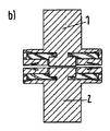
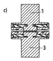
a)(移動および固定の)一方の電極の内側コンタクトは、外側コンタクトと比較して上昇し、対向電極の内側部品の位置は下降している(または内側に押し込まれている)。図2cを参照。 a) The inner contact of one electrode (moving and fixed) is raised compared to the outer contact, and the position of the inner part of the counter electrode is lowered (or pushed inward). See Figure 2c.
b)すべての内側コンタクトおよび外側コンタクトは、同一レベルにある。図2dを参照。 b) All inner and outer contacts are at the same level. See Figure 2d.
この場合、ケース3にて説明したように、力の略全部(99%)は、閉鎖位置において、外側コンタクトの弾性変形のため、内側コンタクトによって保持される。これは、内側コンタクトによる接触抵抗が外側コンタクトによる接触抵抗よりはるかに低いことを意味する。
In this case, as explained in
開放時には、最後の接触点が外側コンタクト間に見出だされるとき、外側コンタクトの弾性変形の特性は、外側コンタクト間にアーク点火を確実にする。 Upon opening, when the last contact point is found between the outer contacts, the elastic deformation characteristics of the outer contacts ensure arc ignition between the outer contacts.
これらの2つの特徴は、この構成に大きい利点を与える。なぜなら、(内側コンタクト間の)公称電流のための低い接触抵抗、および、AMF発生の原因となる外側コンタクト間のアーク点火に有利であるためである。この構成により、完全な拡散アークに対するアーク整流は、短時間で発生する。 These two features give great advantages to this configuration. This is because it is advantageous for low contact resistance for nominal current (between inner contacts) and arc ignition between outer contacts that causes AMF generation. With this configuration, arc rectification for a complete diffusion arc occurs in a short time.
3)第3のケースは、第1のケースの反対であり、すなわち、(開放位置において)外側コンタクト間の間隔距離は、内側コンタクト間の間隔距離より小さい。ただし、この差は、0.1〜2.5mm程度であり、好ましくは、0.5〜1.5mm程度である。ここでもまた、2つのケースを区別することができる。 3) The third case is the opposite of the first case, i.e. the distance between the outer contacts (in the open position) is smaller than the distance between the inner contacts. However, this difference is about 0.1 to 2.5 mm, and preferably about 0.5 to 1.5 mm. Again, two cases can be distinguished.
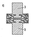
a)両方の内側コンタクトは、外側コンタクトと比較して内側に(非常に短い距離ではあるが)押し込まれている。図2fを参照。 a) Both inner contacts are pushed inward (although at a very short distance) compared to the outer contacts. See Figure 2f.
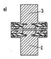
b)一方の電極の内側コンタクトは、内側に押し込まれ、対向電極の他方の内側コンタクトは、外側コンタクトと同一レベルに保たれている。図2eを参照。 b) The inner contact of one electrode is pushed inward and the other inner contact of the counter electrode is kept at the same level as the outer contact. See Figure 2e.
それぞれの間隔距離の相違、および、外側コンタクトコイルの弾性に応じて、内側コンタクトは、接触しているか、閉鎖位置にないか、のいずれかである。内側コンタクト間のそれぞれの間隔距離が大きい場合および/または外側コンタクトコイルの弾性が低い場合、力全体は、外側コンタクトによって保たれる(ケース1)、しかし、内側コンタクト間のそれぞれの間隔距離が小さい場合および/または外側コンタクトコイルの弾性が大きい場合、大部分の力は、内側コンタクトによって保たれる(ケース2)。この場合、アーク点火は外側コンタクトで開始するが、(外側コンタクトの変形を増加させるために)外側コンタクトの弾性特性が変えられない限り、(公称電流のための)内側コンタクトの接触抵抗は増加する。外側コンタクトの弾性が、外側コンタクトの直径、カップ厚およびカップ材料によって影響されうることに気付くことは重要である。 Depending on the difference in distance between each and the elasticity of the outer contact coil, the inner contact is either in contact or not in the closed position. If the respective spacing distance between the inner contacts is large and / or if the elasticity of the outer contact coil is low, the entire force is retained by the outer contact (case 1), but the respective spacing distance between the inner contacts is small. If and / or if the outer contact coil is highly elastic, most of the force is retained by the inner contact (case 2). In this case, arc ignition starts at the outer contact, but the contact resistance of the inner contact (for nominal current) increases unless the elastic properties of the outer contact are changed (to increase the deformation of the outer contact). . It is important to note that the elasticity of the outer contact can be affected by the outer contact diameter, cup thickness and cup material.
他の実施形態によれば、(カップ形状の)外側コンタクトは、二重層または多層から構成され、少なくとも1層はステンレス鋼のような強く、弾性があり、導電性の材料から成り、少なくとも第2の層は、銅のような高熱伝導性材料から成る。この組合せは、ロバストさおよびコスト効果の基準をコンタクト・アセンブリに提供し、アーク放電中およびアーク放電後のより良好な熱管理を保証する(高速なコンタクトの冷却)。 According to another embodiment, the (cup-shaped) outer contact is composed of a double layer or multiple layers, at least one layer being made of a strong, elastic, conductive material, such as stainless steel, and at least a second This layer consists of a highly thermally conductive material such as copper. This combination provides a robust and cost effective criterion for the contact assembly and ensures better thermal management during and after arcing (fast contact cooling).
多層のカップ形状のコンタクトは、目的の用途に応じて、層の重ね合せ順序のさまざまな構成を有することができる。以下、二重層の実施例を示す。 Multi-layer cup-shaped contacts can have various configurations of layer stacking order, depending on the intended application. Examples of double layers are shown below.
1)内側層は、ステンレス鋼(硬い導電材料)から成り、外側層は、銅(優れた熱導体および導電体)から成る。この場合、短絡電流の大部分は外側層(銅)を通過するので、有効なAMF領域を増加させる。この構成は、増加した大電流遮断性能のために望ましい。 1) The inner layer is made of stainless steel (hard conductive material) and the outer layer is made of copper (excellent thermal conductor and conductor). In this case, most of the short circuit current passes through the outer layer (copper), thus increasing the effective AMF area. This configuration is desirable for increased high current interrupt performance.
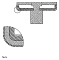
2)内側層は、銅から成り、外側層は、ステンレス鋼から成る。ここで、カップ形状のコンタクトの外側層は、ステンレス鋼から成るので、シールドの方への高電圧に耐えることを考慮されうる。この構成は、高圧用途のための良好なオプションとなりうる。接触力分布は、図示するように外側コンタクトの弾性の変化により、これらの2つの構成を用いることにより僅かに変化する。例えば、図3を参照。外側コンタクト間の力は、ステンレス鋼の単層の場合の100Nから、二重層を用いると70Nに減少した。 2) The inner layer is made of copper and the outer layer is made of stainless steel. Here, since the outer layer of the cup-shaped contact is made of stainless steel, it can be considered to withstand high voltages towards the shield. This configuration can be a good option for high pressure applications. The contact force distribution is slightly changed by using these two configurations due to changes in the elasticity of the outer contacts as shown. For example, see FIG. The force between the outer contacts was reduced from 100 N for the stainless steel single layer to 70 N using the double layer.
3)あるいは、内側層は、ステンレス鋼から成り、第2の層は、銅から成る。第3の薄層は、第2の外層上に重ねられ、ステンレス鋼または高電圧の良好な耐性を有する他の金属(ニッケル、合金鋼など)から成る。例えば、この薄層は、電気メッキ、電鋳またはPVDプロセス、などを有するコーティングによって得られる。この多層構造により、真空遮断器において、高い電流遮断プロセス中の有効なAMF領域を増加させ、高電圧の耐性を増加させる。 3) Alternatively, the inner layer is made of stainless steel and the second layer is made of copper. The third thin layer is overlaid on the second outer layer and consists of stainless steel or other metal (nickel, alloy steel, etc.) with good resistance to high voltages. For example, this thin layer can be obtained by coating with electroplating, electroforming or PVD processes, and the like. This multi-layer structure increases the effective AMF area during the high current interrupt process and increases the high voltage tolerance in the vacuum circuit breaker.
4)あるいは、多層カップ形状のコンタクトの逆の配置も可能である。内側層は、銅から成り、外側層は、ステンレス鋼から成る(ステンレス鋼層はコンタクトの頑丈さのために必要である)。ステンレス鋼の層は、銅の薄層によって重ねられ、銅の薄層は、電気メッキ、電鋳またはPVDプロセス等のコーティングによって得られる。 4) Alternatively, the arrangement of contacts in the shape of a multilayer cup can be reversed. The inner layer is made of copper and the outer layer is made of stainless steel (the stainless steel layer is necessary for contact robustness). The stainless steel layer is overlaid by a thin copper layer, which is obtained by coating such as electroplating, electroforming or PVD process.
それゆえ、図3a、図3b、図3cおよび図3dは、異なる実施形態を示す。 Therefore, Figures 3a, 3b, 3c and 3d show different embodiments.
図3aは、ステンレス鋼の内側層および銅の外側層を備える二重層システムを示す。 FIG. 3a shows a double layer system with an inner layer of stainless steel and an outer layer of copper.
図3bは、銅の内側層およびステンレス鋼の外側層を備える二重層システムを示す。 FIG. 3b shows a double layer system with an inner layer of copper and an outer layer of stainless steel.
図3cは、ステンレス鋼の内側層と、銅の外側層と、鋼/ニッケルの薄いカバー層と、を備える多層システムを示す。 FIG. 3c shows a multilayer system comprising an inner layer of stainless steel, an outer layer of copper, and a thin cover layer of steel / nickel.
図3dは、銅の内側層と、ステンレス鋼の外側層と、銅の薄いカバー層と、を備える多層システムを示す。 FIG. 3d shows a multilayer system comprising an inner layer of copper, an outer layer of stainless steel, and a thin cover layer of copper.
Claims (14)
内側コンタクトは、同心のカップ形状のAMFコイル内に配置されるTMFのような形状またはピン形状を有し、
両側に、すなわち、固定コンタクト配置側および移動コンタクト配置側に、単層または多層で配置されたコンタクト部品を有し、
カップ形状の外側コンタクトは、単層、二重層または多層の構成から成り、
少なくとも1つの層は、硬鋼または合金鋼から成り、
多層構成の場合には、少なくとも第2の層は、高熱伝導性を有する材料から成る、
真空遮断器。 A vacuum circuit breaker having a double coaxial contact configuration,
The inner contact has a TMF-like shape or pin shape placed in a concentric cup-shaped AMF coil;
Having contact parts arranged in a single layer or multiple layers on both sides, i.e. on the fixed contact placement side and on the moving contact placement side,
The cup-shaped outer contact consists of a single layer, double layer or multiple layer configuration,
At least one layer consists of hard steel or alloy steel;
In the case of a multilayer configuration, at least the second layer is made of a material having high thermal conductivity,
Vacuum circuit breaker.
請求項1に記載の真空遮断器。 The material having high thermal conductivity is copper, silver, a silver alloy or a copper alloy.
The vacuum circuit breaker according to claim 1.
請求項1に記載の真空遮断器。 Hard steel or alloy steel is stainless steel,
The vacuum circuit breaker according to claim 1.
請求項1〜3のいずれかに記載の真空遮断器。 The inner layer of the double-layer or multi-layer contact configuration is made of stainless steel or other material of comparable rigidity, and the outer layer or the second layer is made of copper;
The vacuum circuit breaker in any one of Claims 1-3.
請求項1〜3のいずれかに記載の真空遮断器。 In the case of a cup-shaped contact configuration, the inner layer of the contact configuration is made of copper, and the other or outer layer is made of stainless steel.
The vacuum circuit breaker in any one of Claims 1-3.
請求項1〜4のいずれかに記載の真空遮断器。 The outer layer is covered or coated with a thin layer made of a material resistant to high voltages, with a thickness of 100 μm or less,
The vacuum circuit breaker in any one of Claims 1-4.
請求項6に記載の真空遮断器。 The material of the thin layer is nickel, steel or alloy steel,
The vacuum circuit breaker according to claim 6.
請求項1〜3、5のいずれかに記載の真空遮断器。 The outer layer is covered or coated with a thin layer made of copper, silver or copper alloy and having a thickness of 100 μm or less.
The vacuum circuit breaker in any one of Claims 1-3.
請求項1〜8のいずれかに記載の真空遮断器。 When the vacuum circuit breaker is in the closed position, the contact components are arranged such that only the inner contact is in contact and the entire nominal current flows through the inner contact;
The vacuum circuit breaker in any one of Claims 1-8.
請求項1〜8のいずれかに記載の真空遮断器。 In the open position of the vacuum circuit breaker, the distance between the inner contacts and the distance between the outer contacts are kept the same.
The vacuum circuit breaker in any one of Claims 1-8.
請求項1〜8のいずれかに記載の真空遮断器。 In the open position of the vacuum circuit breaker, the distance between the outer contacts is smaller than the distance between the inner contacts,
The vacuum circuit breaker in any one of Claims 1-8.
請求項1、9〜11のいずれかに記載の真空遮断器。 In the closed position of the vacuum circuit breaker, the whole or substantially the whole of the nominal current flows in the inner contact,
The vacuum circuit breaker in any one of Claims 1 and 9-11.
アーク点火は、前記内側コンタクト間に発生し、
部分的にまたは全体的に前記外側コンタクトに伝わり、前記外側コンタクト内の電流に対応して生成されたAMFの影響の下、拡散アークに変わる、
請求項1または9に記載の真空遮断器。 When opening (separating) the contact of the vacuum circuit breaker during the current interruption process,
Arc ignition occurs between the inner contacts,
Partially or wholly transmitted to the outer contact and converted into a diffusion arc under the influence of the AMF generated in response to the current in the outer contact;
The vacuum circuit breaker according to claim 1 or 9.
アーク点火は、前記外側コンタクト間に発生し、
前記外側コンタクト内の電流に対応して生成されたAMFの影響の下、拡散アークに急速に変わる、
請求項1、10〜12のいずれかに記載の真空遮断器。 When opening (separating) the contact of the vacuum circuit breaker during the current interruption process,
Arc ignition occurs between the outer contacts,
Under the influence of the AMF generated corresponding to the current in the outer contact, it rapidly changes to a diffuse arc.
The vacuum circuit breaker in any one of Claim 1, 10-12.
Applications Claiming Priority (5)
| Application Number | Priority Date | Filing Date | Title |
|---|---|---|---|
| EP12004395 | 2012-06-11 | ||
| EP12004395.5 | 2012-06-11 | ||
| EP12007203.8A EP2674955B1 (en) | 2012-06-11 | 2012-10-18 | Vacuum interrupter with double coaxial contact arrangement at each side |
| EP12007203.8 | 2012-10-18 | ||
| PCT/EP2013/001708 WO2013185906A1 (en) | 2012-06-11 | 2013-06-11 | Vacuum interrupter with double coaxial contact arrangement at each side |
Publications (1)
| Publication Number | Publication Date |
|---|---|
| JP2015519713A true JP2015519713A (en) | 2015-07-09 |
Family
ID=47044725
Family Applications (1)
| Application Number | Title | Priority Date | Filing Date |
|---|---|---|---|
| JP2015516506A Pending JP2015519713A (en) | 2012-06-11 | 2013-06-11 | Vacuum circuit breaker with double coaxial contact configuration on both sides |
Country Status (6)
| Country | Link |
|---|---|
| US (1) | US20150114931A1 (en) |
| EP (2) | EP2674955B1 (en) |
| JP (1) | JP2015519713A (en) |
| CN (1) | CN104488057A (en) |
| IN (1) | IN2014DN10567A (en) |
| WO (1) | WO2013185906A1 (en) |
Citations (2)
| Publication number | Priority date | Publication date | Assignee | Title |
|---|---|---|---|---|
| JPS56138836A (en) * | 1980-03-31 | 1981-10-29 | Meidensha Electric Mfg Co Ltd | Vacuum breaker |
| JPS6065413A (en) * | 1983-09-20 | 1985-04-15 | 株式会社東芝 | Vacuum breaker |
Family Cites Families (11)
| Publication number | Priority date | Publication date | Assignee | Title |
|---|---|---|---|---|
| US3210505A (en) * | 1962-04-03 | 1965-10-05 | Gen Electric | Electrode structure for an electric circuit interrupter |
| US3980850A (en) * | 1974-12-19 | 1976-09-14 | Westinghouse Electric Corporation | Vacuum interrupter with cup-shaped contact having an inner arc controlling electrode |
| US4847456A (en) * | 1987-09-23 | 1989-07-11 | Westinghouse Electric Corp. | Vacuum circuit interrupter with axial magnetic arc transfer mechanism |
| DE9305125U1 (en) * | 1993-03-30 | 1994-08-04 | Siemens AG, 80333 München | Contact arrangement for a vacuum interrupter |
| TW264530B (en) * | 1993-12-24 | 1995-12-01 | Hitachi Seisakusyo Kk | |
| DE10221363C1 (en) * | 2002-05-07 | 2003-12-24 | Siemens Ag | Pot-shaped switch contact with metal vapor shield |
| US6965089B2 (en) * | 2003-02-21 | 2005-11-15 | Mcgraw-Edison Company | Axial magnetic field vacuum fault interrupter |
| EP1766646B1 (en) * | 2004-07-05 | 2016-05-04 | ABB Research Ltd. | Vacuum interrupter and contact arrangement for a vacuum interrupter |
| CN101164130A (en) * | 2005-04-16 | 2008-04-16 | Abb技术股份公司 | Method of manufacturing contact element for vacuum switch case |
| DE102006042101B4 (en) * | 2006-09-07 | 2008-09-25 | Switchcraft Europe Gmbh | Vacuum switch for medium and high voltages |
| EP2434513B1 (en) | 2010-09-24 | 2019-04-17 | ABB Schweiz AG | Electrical contact arrangement for vacuum interrupter arrangement |
-
2012
- 2012-10-18 EP EP12007203.8A patent/EP2674955B1/en active Active
- 2012-10-18 EP EP20189894.7A patent/EP3754684A1/en active Pending
-
2013
- 2013-06-11 JP JP2015516506A patent/JP2015519713A/en active Pending
- 2013-06-11 IN IN10567DEN2014 patent/IN2014DN10567A/en unknown
- 2013-06-11 CN CN201380038542.1A patent/CN104488057A/en active Pending
- 2013-06-11 WO PCT/EP2013/001708 patent/WO2013185906A1/en active Application Filing
-
2014
- 2014-12-11 US US14/567,489 patent/US20150114931A1/en not_active Abandoned
Patent Citations (2)
| Publication number | Priority date | Publication date | Assignee | Title |
|---|---|---|---|---|
| JPS56138836A (en) * | 1980-03-31 | 1981-10-29 | Meidensha Electric Mfg Co Ltd | Vacuum breaker |
| JPS6065413A (en) * | 1983-09-20 | 1985-04-15 | 株式会社東芝 | Vacuum breaker |
Also Published As
| Publication number | Publication date |
|---|---|
| EP2674955B1 (en) | 2020-12-02 |
| US20150114931A1 (en) | 2015-04-30 |
| CN104488057A (en) | 2015-04-01 |
| IN2014DN10567A (en) | 2015-08-28 |
| EP3754684A1 (en) | 2020-12-23 |
| EP2674955A1 (en) | 2013-12-18 |
| WO2013185906A1 (en) | 2013-12-19 |
Similar Documents
| Publication | Publication Date | Title |
|---|---|---|
| US9330868B2 (en) | Contact assembly for a vacuum circuit breaker | |
| US7906742B2 (en) | Vacuum interrupter chamber and contact arrangement for a vacuum circuit breaker | |
| RU2507624C2 (en) | Vacuum interrupter for vacuum circuit breaker | |
| EP2434513A1 (en) | Electrical contact arrangement for vacuum interrupter arrangement | |
| TWI607464B (en) | Sequential switching device with surrounding heterogeneous joint points structure | |
| RU2692778C2 (en) | Magnetic switch for strong currents | |
| EP2346061A1 (en) | Electrode structure for vacuum circuit breaker | |
| JP5274676B2 (en) | Vacuum valve | |
| CN101459013B (en) | Longitudinal magnetic field electrode vacuum switch tube with low loop resistance | |
| RU2634749C2 (en) | Coil of axial magnetic field for vacuum interrupter | |
| JP2015519713A (en) | Vacuum circuit breaker with double coaxial contact configuration on both sides | |
| CN108231439B (en) | Electrical contact material | |
| AU2016321594B2 (en) | Switching contact of a vacuum interrupter comprising supporting bodies | |
| US7041929B2 (en) | Contact arrangement for a vacuum switch tube | |
| JP5523594B2 (en) | Switch | |
| WO2015019424A1 (en) | Electric contact point and contact element | |
| JP5525316B2 (en) | Vacuum valve | |
| US20210233730A1 (en) | Electromagnetic actuator, electrical switching unit comprising an electromagnetic actuator of this kind | |
| JP5889549B2 (en) | Current-carrying member for gas insulated switchgear | |
| JP2010251079A (en) | Switch | |
| JP2014116183A (en) | Vacuum valve | |
| JP6579425B2 (en) | Board switch | |
| JP2018181681A (en) | Shrinkage ring and vacuum interrupter | |
| JPS63160122A (en) | Vacuum interruptor | |
| CN115101381A (en) | Coupling type vacuum interrupter cup longitudinal magnetic field electrode structure |
Legal Events
| Date | Code | Title | Description |
|---|---|---|---|
| A621 | Written request for application examination |
Free format text: JAPANESE INTERMEDIATE CODE: A621 Effective date: 20150204 |
|
| A977 | Report on retrieval |
Free format text: JAPANESE INTERMEDIATE CODE: A971007 Effective date: 20151022 |
|
| A131 | Notification of reasons for refusal |
Free format text: JAPANESE INTERMEDIATE CODE: A131 Effective date: 20151102 |
|
| A601 | Written request for extension of time |
Free format text: JAPANESE INTERMEDIATE CODE: A601 Effective date: 20160202 |
|
| A601 | Written request for extension of time |
Free format text: JAPANESE INTERMEDIATE CODE: A601 Effective date: 20160302 |
|
| RD13 | Notification of appointment of power of sub attorney |
Free format text: JAPANESE INTERMEDIATE CODE: A7433 Effective date: 20160318 |
|
| A601 | Written request for extension of time |
Free format text: JAPANESE INTERMEDIATE CODE: A601 Effective date: 20160401 |
|
| A521 | Request for written amendment filed |
Free format text: JAPANESE INTERMEDIATE CODE: A821 Effective date: 20160318 |
|
| A02 | Decision of refusal |
Free format text: JAPANESE INTERMEDIATE CODE: A02 Effective date: 20160704 |


