EP2674715A1 - A plate heat exchanger with thermally drilled hole - Google Patents
A plate heat exchanger with thermally drilled hole Download PDFInfo
- Publication number
- EP2674715A1 EP2674715A1 EP12171915.7A EP12171915A EP2674715A1 EP 2674715 A1 EP2674715 A1 EP 2674715A1 EP 12171915 A EP12171915 A EP 12171915A EP 2674715 A1 EP2674715 A1 EP 2674715A1
- Authority
- EP
- European Patent Office
- Prior art keywords
- plate
- heat exchanger
- hole
- exchanger plates
- package
- Prior art date
- Legal status (The legal status is an assumption and is not a legal conclusion. Google has not performed a legal analysis and makes no representation as to the accuracy of the status listed.)
- Withdrawn
Links
- 238000005553 drilling Methods 0.000 claims abstract description 37
- 239000012530 fluid Substances 0.000 claims abstract description 11
- 238000000034 method Methods 0.000 claims description 18
- 238000005219 brazing Methods 0.000 claims description 5
- 238000003466 welding Methods 0.000 claims description 5
- 239000000853 adhesive Substances 0.000 claims description 4
- 230000001070 adhesive effect Effects 0.000 claims description 4
- 239000011521 glass Substances 0.000 claims description 3
- 238000007689 inspection Methods 0.000 claims description 3
- 239000000463 material Substances 0.000 description 29
- 238000005520 cutting process Methods 0.000 description 7
- 238000004891 communication Methods 0.000 description 5
- 238000007493 shaping process Methods 0.000 description 5
- 239000002826 coolant Substances 0.000 description 3
- 238000005304 joining Methods 0.000 description 3
- 238000004519 manufacturing process Methods 0.000 description 3
- 238000010079 rubber tapping Methods 0.000 description 3
- 230000015572 biosynthetic process Effects 0.000 description 2
- 238000003780 insertion Methods 0.000 description 2
- 230000037431 insertion Effects 0.000 description 2
- 238000005192 partition Methods 0.000 description 2
- 238000012546 transfer Methods 0.000 description 2
- 238000005452 bending Methods 0.000 description 1
- 230000000903 blocking effect Effects 0.000 description 1
- 230000006835 compression Effects 0.000 description 1
- 238000007906 compression Methods 0.000 description 1
- 239000010725 compressor oil Substances 0.000 description 1
- 238000011109 contamination Methods 0.000 description 1
- 238000001816 cooling Methods 0.000 description 1
- 238000006073 displacement reaction Methods 0.000 description 1
- 238000010438 heat treatment Methods 0.000 description 1
- 230000001788 irregular Effects 0.000 description 1
- 238000003754 machining Methods 0.000 description 1
- 238000012544 monitoring process Methods 0.000 description 1
- 230000002093 peripheral effect Effects 0.000 description 1
- 238000003825 pressing Methods 0.000 description 1
- 239000000523 sample Substances 0.000 description 1
- 229910000679 solder Inorganic materials 0.000 description 1
- 238000005482 strain hardening Methods 0.000 description 1
- WFKWXMTUELFFGS-UHFFFAOYSA-N tungsten Chemical compound [W] WFKWXMTUELFFGS-UHFFFAOYSA-N 0.000 description 1
Images




Classifications
-
- B—PERFORMING OPERATIONS; TRANSPORTING
- B21—MECHANICAL METAL-WORKING WITHOUT ESSENTIALLY REMOVING MATERIAL; PUNCHING METAL
- B21J—FORGING; HAMMERING; PRESSING METAL; RIVETING; FORGE FURNACES
- B21J5/00—Methods for forging, hammering, or pressing; Special equipment or accessories therefor
- B21J5/06—Methods for forging, hammering, or pressing; Special equipment or accessories therefor for performing particular operations
- B21J5/063—Friction heat forging
- B21J5/066—Flow drilling
-
- F—MECHANICAL ENGINEERING; LIGHTING; HEATING; WEAPONS; BLASTING
- F25—REFRIGERATION OR COOLING; COMBINED HEATING AND REFRIGERATION SYSTEMS; HEAT PUMP SYSTEMS; MANUFACTURE OR STORAGE OF ICE; LIQUEFACTION SOLIDIFICATION OF GASES
- F25B—REFRIGERATION MACHINES, PLANTS OR SYSTEMS; COMBINED HEATING AND REFRIGERATION SYSTEMS; HEAT PUMP SYSTEMS
- F25B39/00—Evaporators; Condensers
- F25B39/02—Evaporators
- F25B39/022—Evaporators with plate-like or laminated elements
-
- F—MECHANICAL ENGINEERING; LIGHTING; HEATING; WEAPONS; BLASTING
- F28—HEAT EXCHANGE IN GENERAL
- F28D—HEAT-EXCHANGE APPARATUS, NOT PROVIDED FOR IN ANOTHER SUBCLASS, IN WHICH THE HEAT-EXCHANGE MEDIA DO NOT COME INTO DIRECT CONTACT
- F28D9/00—Heat-exchange apparatus having stationary plate-like or laminated conduit assemblies for both heat-exchange media, the media being in contact with different sides of a conduit wall
- F28D9/0006—Heat-exchange apparatus having stationary plate-like or laminated conduit assemblies for both heat-exchange media, the media being in contact with different sides of a conduit wall the plate-like or laminated conduits being enclosed within a pressure vessel
-
- F—MECHANICAL ENGINEERING; LIGHTING; HEATING; WEAPONS; BLASTING
- F28—HEAT EXCHANGE IN GENERAL
- F28D—HEAT-EXCHANGE APPARATUS, NOT PROVIDED FOR IN ANOTHER SUBCLASS, IN WHICH THE HEAT-EXCHANGE MEDIA DO NOT COME INTO DIRECT CONTACT
- F28D9/00—Heat-exchange apparatus having stationary plate-like or laminated conduit assemblies for both heat-exchange media, the media being in contact with different sides of a conduit wall
- F28D9/0031—Heat-exchange apparatus having stationary plate-like or laminated conduit assemblies for both heat-exchange media, the media being in contact with different sides of a conduit wall the conduits for one heat-exchange medium being formed by paired plates touching each other
- F28D9/0043—Heat-exchange apparatus having stationary plate-like or laminated conduit assemblies for both heat-exchange media, the media being in contact with different sides of a conduit wall the conduits for one heat-exchange medium being formed by paired plates touching each other the plates having openings therein for circulation of at least one heat-exchange medium from one conduit to another
- F28D9/005—Heat-exchange apparatus having stationary plate-like or laminated conduit assemblies for both heat-exchange media, the media being in contact with different sides of a conduit wall the conduits for one heat-exchange medium being formed by paired plates touching each other the plates having openings therein for circulation of at least one heat-exchange medium from one conduit to another the plates having openings therein for both heat-exchange media
-
- F—MECHANICAL ENGINEERING; LIGHTING; HEATING; WEAPONS; BLASTING
- F28—HEAT EXCHANGE IN GENERAL
- F28D—HEAT-EXCHANGE APPARATUS, NOT PROVIDED FOR IN ANOTHER SUBCLASS, IN WHICH THE HEAT-EXCHANGE MEDIA DO NOT COME INTO DIRECT CONTACT
- F28D9/00—Heat-exchange apparatus having stationary plate-like or laminated conduit assemblies for both heat-exchange media, the media being in contact with different sides of a conduit wall
- F28D9/0062—Heat-exchange apparatus having stationary plate-like or laminated conduit assemblies for both heat-exchange media, the media being in contact with different sides of a conduit wall the conduits for one heat-exchange medium being formed by spaced plates with inserted elements
-
- F—MECHANICAL ENGINEERING; LIGHTING; HEATING; WEAPONS; BLASTING
- F28—HEAT EXCHANGE IN GENERAL
- F28F—DETAILS OF HEAT-EXCHANGE AND HEAT-TRANSFER APPARATUS, OF GENERAL APPLICATION
- F28F9/00—Casings; Header boxes; Auxiliary supports for elements; Auxiliary members within casings
-
- F—MECHANICAL ENGINEERING; LIGHTING; HEATING; WEAPONS; BLASTING
- F28—HEAT EXCHANGE IN GENERAL
- F28F—DETAILS OF HEAT-EXCHANGE AND HEAT-TRANSFER APPARATUS, OF GENERAL APPLICATION
- F28F9/00—Casings; Header boxes; Auxiliary supports for elements; Auxiliary members within casings
- F28F9/02—Header boxes; End plates
- F28F9/0243—Header boxes having a circular cross-section
-
- F—MECHANICAL ENGINEERING; LIGHTING; HEATING; WEAPONS; BLASTING
- F28—HEAT EXCHANGE IN GENERAL
- F28F—DETAILS OF HEAT-EXCHANGE AND HEAT-TRANSFER APPARATUS, OF GENERAL APPLICATION
- F28F9/00—Casings; Header boxes; Auxiliary supports for elements; Auxiliary members within casings
- F28F9/02—Header boxes; End plates
- F28F9/0246—Arrangements for connecting header boxes with flow lines
- F28F9/0248—Arrangements for sealing connectors to header boxes
-
- F—MECHANICAL ENGINEERING; LIGHTING; HEATING; WEAPONS; BLASTING
- F28—HEAT EXCHANGE IN GENERAL
- F28F—DETAILS OF HEAT-EXCHANGE AND HEAT-TRANSFER APPARATUS, OF GENERAL APPLICATION
- F28F9/00—Casings; Header boxes; Auxiliary supports for elements; Auxiliary members within casings
- F28F9/02—Header boxes; End plates
- F28F9/026—Header boxes; End plates with static flow control means, e.g. with means for uniformly distributing heat exchange media into conduits
- F28F9/027—Header boxes; End plates with static flow control means, e.g. with means for uniformly distributing heat exchange media into conduits in the form of distribution pipes
- F28F9/0273—Header boxes; End plates with static flow control means, e.g. with means for uniformly distributing heat exchange media into conduits in the form of distribution pipes with multiple holes
-
- F—MECHANICAL ENGINEERING; LIGHTING; HEATING; WEAPONS; BLASTING
- F28—HEAT EXCHANGE IN GENERAL
- F28F—DETAILS OF HEAT-EXCHANGE AND HEAT-TRANSFER APPARATUS, OF GENERAL APPLICATION
- F28F9/00—Casings; Header boxes; Auxiliary supports for elements; Auxiliary members within casings
- F28F9/02—Header boxes; End plates
- F28F9/04—Arrangements for sealing elements into header boxes or end plates
- F28F9/16—Arrangements for sealing elements into header boxes or end plates by permanent joints, e.g. by rolling
Definitions
- the present invention refers generally to a plate heat exchanger having at least one through hole being formed by thermal drilling.
- the invention also relates to a method of arranging at least one through hole in a plate heat exchanger.
- Heat exchangers and especially plate heat exchangers are examples of thin walled structures for the provision of an interior channel system for the guiding of one or several fluids between at least one inlet and at least one outlet.
- a typical plate heat exchanger is formed by a plurality of thin heat exchangers plates arranged to form a plate package.
- the plate package is formed by a number of first and second heat exchanger plates.
- the heat exchanger plates may be permanently joined to each other and arranged side by side in such a way that a first plate interspace is formed between each pair of adjacent first and second heat exchanger plates and a second plate interspace is formed between each pair of adjacent second and first heat exchanger plates.
- the first plate interspaces and the second plate interspaces are separated from each other and provided side by side in an alternating order in the plate package.
- each heat exchanger plate has at least a first porthole and a second porthole, wherein the first portholes form a first inlet channel to the first plate interspaces and the second portholes form a first outlet channel from the first plate interspaces.
- the permanently joining may be achieved by welding, brazing, bonding or adhesives.
- the positions of inlets or outlets are depending on the first and second portholes.
- any surface profile of the heat exchanger plates is depending on the position of the inlets and the outlets in order to optimize the flow through the panel interspaces and thereby the thermal efficiency.
- the thin walled lamellae like structure formed by the permanently joined plate heat exchanger makes it very complicated to add additional inlets or outlets, sensors or the like since the positioning thereof is limited to the port holes and the inlet or outlet channels formed thereof.
- the complex and irregular lamellae structure of a permanently joined plate heat exchanger results in an unreliable material for machining and the inner structures in the inlet or outlet ports may collapse. Generally it is hard to even create surfaces to seal against in a permanently joined plate heat exchanger. Further, provided the permanent joining is achieved by brazing, it is difficult to solder or weld connections, such as weld bolts, without destroying the brazed structure. Additionally, it is very hard to make large holes covering one or several plate interspaces.
- the object of the present invention is to provide a plate heat exchanger having at least one through hole remedying the problems mentioned above.
- Another object is to provide a method allowing an essentially arbitrary positioning of a through hole in a plate heat exchanger.
- the method should be applicable to high volume production where a high degree of reliability and repeatability is required.
- a plate heat exchanger including a plate package which plate package includes a plurality of heat exchanger plates of at least two configurations which are joined to each other and which alternate with each other to form a stack of heat exchanger plates forming plate interspaces between the heat exchanger plates, the plate interspaces being arranged to receive at least two different fluids.
- the plate heat exchanger is characterized in that at least one through hole is arranged to extend between the exterior of the plate package and a compartment inside the plate package, the compartment being at least partly formed by any of the plate interspaces, wherein the at least one through hole is formed by a thermal drilling
- Thermal drilling also known as flow drilling, friction drilling or form drilling is a non-cutting method providing a plastic re-shaping of the material.
- the hole is formed by rotating a pin-like tool having a circular cross section with a diameter essentially corresponding to the hole to be formed. During rotation, the tool creates a hole by relying on the friction that results from the high rotational speed. The generated heat makes the material malleable enough to be formed and perforated.
- the tip of the tool penetrates the lower surface of the base material, the displaced material starts to flow in the direction of the tool feed. Some displaced material may form a collar around the upper surface of the work piece. The rest of the material may form a sleeve-like bushing in the lower surface.
- the formed sleeve is remarkably strong and may by way of example be threaded in a separate process.
- Thermal drilling has surprisingly proven to be applicable to thin-walled, honeycomb-like structures such as plate heat exchangers. Further, thermal drilling is a non-cutting method leaving no contaminating chips which may cause uncontrolled throttling or blocking in the narrow passages in the interior of the plate heat exchanger. Also, there is no risk of chips being formed that might constitute problems for devices to be arranged downstream of a plate heat exchanger, such as a compressor.
- the combination of the honeycomb-like structure and the strict requirement of no chip formation has traditionally made hole making in joined plate heat exchangers very complicated and in fact something that has generally been avoided where possible. This is especially the case in high volume production.
- thermal drilling By using thermal drilling, completely new possibilities concerning access to the interior of the plate package of a permanently joined plate heat exchanger are provided. This involves insertion of instruments such as sensors, cameras or the like to improve the monitoring and understanding of the operational conditions inside the plate heat exchanger. Also, it provides completely new possibilities regarding positioning of inlets or outlets for fluid supply or tubings used therefore. In fact, the thermal drilling allows an essentially arbitrary positioning of a through hole in a plate heat exchanger. Further, by thermal drilling it is made possible to make large holes providing access to more than one plate interspace.
- the compartment may comprise a plurality of plate interspaces communicating with each other via a common channel, wherein the at least one through hole is arranged in a wall portion defining the common channel.
- the wall portion may be the circumferential envelope surface of the common channel or a longitudinal end surface thereof.
- the common channel may by way of example be an inlet or an outlet channel extending through or along the plate package.
- the at least one through hole may be arranged to receive a component contained in the group consisting of sensors such as temperature sensors, pressure sensors and optic sensors, plugs, such as drainage plugs or inspection glasses and connectors for tubings. It is to be understood that these are not limiting examples of components possible to be applied.
- the longitudinal axis of the at least one through hole may be arranged to extend essentially in parallel with a general plane of the longitudinal extension of the heat exchanger plates.
- the at least one through hole may be arranged in a wall portion defining a circumferential side wall of the plate package, the side wall extending essentially perpendicular to a general plane of the longitudinal surface extension of the heat exchanger plates.
- the at least one through hole may have a diameter providing access to more than one plate interspace.
- the at least one through hole may be arranged in an upper or a lower end plate forming part of the plate package.
- the heat exchanger plates in the plate package may be permanently joined to each other through brazing, welding, adhesive or bonding.
- the at least one through hole may comprise a longitudinal envelope surface defining a sleeve having a longitudinal extension being coaxial with the longitudinal axis of the through hole, and the sleeve may have a free edge portion facing the interior of the compartment.
- the sleeve may be used for threading or for the receipt of a bushing, lining, connector or the like.
- the sleeve may also be used to provide a channel past one or several plate interspaces to thereby provide enhanced access to the interior structure of the plate package allowing insertion of e.g. a sensor.
- the mouth of the at least one through hole facing away from the compartment may comprise a circumferential collar formed during the thermal drilling.
- Such circumferential collar may be used for connection of a component to be inserted into the through hole.
- the at least one through hole may comprise a threaded portion.
- the plate heat exchanger may further comprise a a bracket arranged in or around the mouth of the at least one through hole. Such bracket may be used for mounting of a component to be inserted into the through hole.
- the stack of the plate package may include a number of first heat exchanger plates and a number of second heat exchanger plates, which are joined to each other and arranged side by side in such a way that a first plate interspace is formed between each pair of adjacent first heat exchanger plates and second heat exchanger plates, and a second plate interspace is formed between each pair of adjacent second heat exchanger plates and first heat exchanger plates.
- the first plate interspaces and the second plate interspaces may be separated from each other and provided side by side in an alternating order in the at least one plate package.
- the invention may relate to a method of providing a through hole in a plate heat exchanger, the method comprising providing a plate heat exchanger comprising a plate package, which plate package includes a plurality of heat exchanger plates of at least two configurations which are joined to each other and which alternate with each other to form a stack of heat exchanger plates forming plate interspaces between the heat exchanger plates, the plate interspaces being arranged to receive at least two different fluids; and arranging by thermal drilling at least one through hole extending between the exterior of the plate package and a compartment inside the plate package, the compartment being at least partly formed by any of the plate interspaces.
- Figs. 1 to 3 disclose a typical example of a plate heat exchanger 1.
- the plate heat exchanger 1 includes a plate package P, which is formed by a number of compression molded heat exchanger plates A, B, which are provided side by side of each other to thereby form a stack 2.
- the heat exchanger plates included in the embodiment are two different heat exchanger plates, which in the following are called the first heat exchanger plates A, see Figs. 3 , 4 and 6 , and the second heat exchanger plate B, see Figs. 3 , 5 and 6 .
- the plate package P includes substantially the same number of first heat exchanger plates A and second heat exchanger plates B.
- the heat exchanger plates A, B are provided side by side in such a way that a first plate interspace 3 is formed between each pair of adjacent first heat exchanger plates A and second heat exchanger plates B, and a second plate interspace 4 between each pair of adjacent second heat exchanger plates B and first heat exchanger plates A. Every second plate interspace thus forms a respective first plate interspace 3 and the remaining plate interspaces form a respective second plate interspace 4, i. e. the first and second plate interspaces 3 and 4 are provided in an alternating order in the plate package P. Furthermore, the first and second plate interspaces 3 and 4 are substantially completely separated from each other.
- a plurality of compartments 5 are thus formed inside the plate package P.
- a first compartment 51 is formed at least partly by any of the first plate interspaces 3 and a second compartment 52 is formed at least partly by any of the second plate interspaces 4.
- the plate package P also includes an upper end plate 6 and a lower end plate 7, which are provided on a respective side of the plate package P.
- the plate heat exchanger 1 may advantageously be adapted to operate as an evaporator in a cooling agent circuit, not disclosed.
- the first plate interspaces 3 may form passages for a first fluid, such as a cooling agent
- the second plate interspaces 4 may form passages for a second fluid, which is adapted to be cooled by the cooling agent.
- the heat exchanger plates A, B and the upper and lower end plates 6, 7 are permanently connected to each other.
- Such a permanent connection may advantageously be performed through brazing, welding, adhesive or bonding.
- substantially each heat exchanger plate A, B has four portholes 8, namely a first porthole 8, a second porthole 8, a third porthole 8 and a fourth porthole 8.
- the first portholes 8 form a first inlet channel 9 to the first plate interspaces 3, which extends through substantially the whole plate package P, i. e. all plates A, B and also the upper end plate 6.
- the second portholes 5 form a first outlet channel 10 from the first plate interspaces 3, which also extends through substantially the whole plate package P, i. e. all plates A, B and the upper end plate 6.
- the third portholes 5 form a second inlet channel 11 to the second plate interspaces 4, and the fourth portholes 5 form a second outlet channel 12 from the second plate interspaces 4. Also these two channels 11 and 12 extend through substantially the whole plate package P, i. e. all plates A, B and the upper end plate 6.
- first inlet channel 9 being in communication with the first plate interspaces 3 may be seen as a part of the first compartment 51.
- the first outlet channel 10, being in communication with the first plate interspaces 3, may also be seen as forming part of the first compartment 51.
- the second inlet channel 11 being in communication with the second plate interspaces 4 may be seen as a part of the second compartment 52.
- the second outlet channel 12, being in communication with the second plate interspaces 4, may also be seen as forming part of the second compartment 52.
- the first plate interspace 3 is accessed via the first inlet channel 9 or the first outlet channel 10, i.e. via the first compartment 51.
- the second plate interspace 4 is accessed via the second inlet channel 11 or the second outlet channel 12, i.e. via the second compartment 52.
- any instruments, sensors or the like are inserted via one of these channels 9, 10, 11, 12, whereby they allow access along the longitudinal extension of one of these channels.
- this only allow access to a strict limited area of the interior of the plate heat exchanger, and especially, it allows no access to the heat transfer surface of an individual heat exchanger plate A, B. Access to such area is cumbersome and is for practical reasons not possible during normal use of a system produced in large scale.
- FIG. 6 disclosing a schematic cross section of an inlet channel 9; 11 or an outlet channel 10; 12 of a typical plate heat exchanger 1 describing one embodiment of the invention.
- the cross section is restricted to the area in and around an inlet or outlet channel 9; 10; 11; 12, the same principle is applicable to any exterior wall portion of the plate package P of a plate heat exchanger 1.
- Fig. 6 discloses a plurality of first and second heat exchanger plates A, B provided side by side in such a way that a first plate interspace 3 is formed between each pair of adjacent first heat exchanger plates A and second heat exchanger plates B, and a second plate interspace 4 between each pair of adjacent second heat exchanger plates B and first heat exchanger plates A. Every second plate interspace thus forms a respective first plate interspace 3 and the remaining plate interspaces form a respective second plate interspace 4, i. e. the first and second plate interspaces 3 and 4 are provided in an alternating order in the plate package P. Furthermore, the first and second plate interspaces 3 and 4 are substantially completely separated from each other.
- the circumferential side wall 13 of the plate package P comprises a plurality of outwardly extending flanges 14, each flange 14 being formed by the outer peripheral edge portion 15 of a pair of adjacent first heat exchanger plates A and second heat exchanger plates B.
- the circumferential side wall 13 extends essentially perpendicular to a general plane 16 of the first and the second heat exchanger plates A, B.
- a plurality of through holes 20 are arranged in the circumferential side wall 13 of the plate package P.
- the through holes 20 are made by thermal drilling. Thermal drilling as a method will be described below.
- the longitudinal axis L of each through hole 20 is arranged to extend essentially in parallel with the general plane 16 of the first and the second heat exchanger plates A, B.
- each first plate interspace 3 comprises a through hole 20 extending from the exterior of the plate package P into the through channel being an inlet channel 9; 11 or an outlet channel 10; 12. It is to be understood that other hole patterns than that illustrated may be used. Further, it is to be understood that by thermal drilling, the through hole 20 may be arranged in any arbitrary position along the circumferential side wall 13 of the plate package P.
- the through holes 20 are arranged with their longitudinal axis L somewhat displaced from the adjacent flanges 14, whereby the through holes 20 are essentially made through a portion of either of the first or the second heat exchanger plates A, B which together form a pair of heat exchanger plates A, B. It is to be understood that other positions are possible.
- the circumferential side wall 13 of the plate package P may be essentially smooth. This may be made e.g. by bending the plurality of outwardly extending flanges 14 to extend essentially in parallel with the circumferential wall portion 13 or by cutting off the flanges 14. It is also to be understood that the cross section depends on the surface pattern 21 of the heat exchanger plates A, B constituting the plate package P.
- a through hole 20 is arranged in the upper end plate 6, whereby a communication is made possible from the exterior of the plate package P to the plate interspace 3; 4 closest to the upper end plate 6.
- the through hole 20 extends into a first plate interspace 3, i.e. the first compartment 51. Any arbitrary position is possible depending on the intended use of the through hole 20. The same principle is applicable to the lower end plate 7.
- Fig. 6 also discloses a through hole 20 arranged in the lower end plate 7.
- the through hole 20 extends past the plate interspace 3; 4 closest to the lower end plate 7 and into the second, subsequent plate interspace 3; 4.
- the longitudinal axis L of the through hole 20 extends through a joint 22 between the two joined heat exchanger plates A, B. It is to be understood that other positions are possible.
- Fig. 6 discloses one embodiment of a through hole 20 having a diameter that provides access to more than one first or second plate interspace 3, 4.
- the through hole 23 is disclosed with an area extending across a plurality of heat exchanger plates A, B and thereby the partition walls 24 between two or several plate interspaces 3, 3; 4, 4, which partition walls 24 are formed by the heat exchanger plates A, B as such.
- Thermal drilling also known as flow drilling, friction drilling or form drilling is a non-cutting method used to form a hole.
- the hole may be a through hole or a blind hole.
- the process is illustrated in Figs. 7a-7c .
- the thermal drilling provides a plastic re-shaping of the material.
- the hole 20 is formed by rotating a pin-like tool 30 having a circular cross section with a diameter essentially corresponding to the hole to be formed, see Fig. 7a .
- the tool 30 has a cone shaped free end 31 engaging a base material 32 with a high rotational speed and with a relatively high axial pressure to thereby form a hole 20.
- the tool 30 may be made by way of example carbide, such as Wolfram carbide.
- the tool 30 creates a hole, see Fig. 9b by relying on the friction that results from the high rotational speed.
- the generated heat makes the base material 32 malleable enough to be formed and perforated.
- a material displacement occurs, see Fig. 7c .
- the displaced material flows upwards towards the tool.
- the tip of the free end 31 of the tool 30 penetrates the lower surface 33 of the base material 32, the displaced material starts to flow in the direction of the tool feed.
- the axial force is reduced and the feed rate is increased.
- Some displaced material may form a collar 34 around the upper surface 35 of the base material 32.
- the rest of the material forms a sleeve 36 in the lower surface 33.
- the collar 34 and the sleeve 36 will be coaxial with the resulting through hole 20 and have a longitudinal extension L slightly exceeding the thickness of the base material 32.
- the degree of work hardening depends on the material.
- the formed sleeve 36 is remarkably strong and may by way of example be threaded in a separate process, see Fig. 7d .
- the threading may be made either internally or externally of the sleeve 36. It is to be understood that the threading 37 may be limited to a portion of the collar 34, the base material 32 and the sleeve 36.
- Standard drilling, NC, and CNC machines are all suitable for thermal drilling. But the process depends on the speed and force with which the specialized tool 30 engages the base material 32. It is to be understood that parameters such as hole size, material, and thickness all influence the suitable rotational speed, feed rate, and axial force. For example, thin materials may bend or collapse under excessive pressure, necessitating adequate support to prevent deformation. Predrilled holes may reduce the required axial force and also leave a smooth finish in the sleeve's lower edge. However, due to chipformation, predrilling is normally not an option when applied to heat exchangers.
- thermal drilling being a non-cutting method no chips are formed that might fall into and contaminate the plate heat exchanger, such as a permanently joined plate package, or any devices to be arranged downstream such plate heat exchanger.
- Thermal drilling has surprisingly proven to be excellent to when making large holes 23 having diameters straddling a plurality of plate interspaces 3, 3; 4, 4, like in a plate heat exchanger 1.
- the sleeve 36 is to be threaded, this may be made by using thermal tapping, basically using the same principle as with thermal drilling with the essential difference that the temperatures are much lower.
- Thermal tapping provides a plastic re-shaping of the material.
- the used tool 38 see Fig. 7d , has threads 38a and when inserted into the hole 20 during rotation, the material in the envelope surface of the hole flows into the thread depression and the crest 38a of the tool 38. Thus, the threads are cold formed leaving no chips.
- the thread form, the depth and the strength is decided by the elected tool 38.
- the treading may be made by a non-cutting conventional plastic cold forming.
- a schematic cross section of a through hole 20 made by thermal drilling is disclosed.
- the mouth 39 of the through hole 20 intended to face away from the plate interspace 3; 4 may comprise the circumferential collar 34 of displaced material. It is possible to shape the collar 34 by the tool 30 used during the thermal drilling to control the shape of the collar 34.
- the through hole 20 comprises on its lower side a longitudinal envelope surface defining the sleeve 36 having a longitudinal extension being coaxial with the longitudinal axis L of the through hole 20.
- the sleeve 36 has a free edge portion 40.
- the sleeve 36 is the result of the thermal drilling being a plastic re-shaping method.
- the through hole 20 may be threaded.
- the threading may be made along the full interior envelope surface 41 of the through hole 20, i.e. from the outer edge of the collar 34 to the free edge portion 40 of the sleeve 36. Alternatively, only a portion of the envelope surface 41 be threaded.
- the collar 34 may be used as connecting surface for any device, or for brackets or the like.
- the through holes 20 may be used to receive or mount different types of sensors (not disclosed) such as temperature sensors, pressure sensors and optic sensors.
- the through holes 20 may also be used to mount plugs (not disclosed), such as drainage plugs or inspection glasses. Typical drainage plugs are drainage plugs for compressor oil and drainage plugs for system evacuation.
- the through holes 20 may also be used as separate inlets or outlets (not disclosed) for reversed cooling/heating duties.
- the invention has generally been described based on a plate heat exchanger 1 having first and second plate interspaces 3; 4 and four port holes 8 allowing a flow of two fluids. It is to be understood that the invention is applicable also for plate heat exchangers having different configurations in terms of the number of plate interspaces, the number of port holes and the number of fluids to be handled. The invention is even applicable to plate heat exchangers wherein one or several inlet or outlet channels formed as through holes integrated in the heat exchanger plates are omitted. It is further to be understood that the invention is applicable no matter type of heat exchanger. It may by way of example be applied to heat exchangers of the tube and shell type or spiral heat exchangers.
- the four portholes 8 are in the disclosed embodiment provided in the proximity of a respective corner of the substantially rectangular heat exchanger plates A, B. It is to be understood that other positions are possible, and the invention should not be limited to the illustrated and disclosed positions.
- the invention is also applicable to plate heat exchangers (not disclosed) comprising pairwise permanently joined heat exchanger plates, wherein each pair forms a cassette.
- gaskets are arranged between each cassette.
- the heat exchanger plates forming each cassette may be permanently joined by welding.
- the invention is also applicable to plate heat exchangers (not disclosed) where the plate package is kept together by tie-bolts extending through the heat exchanger plates and the upper and lower end plates. In the latter case gaskets are used between the heat exchanger plates.
Landscapes
- Engineering & Computer Science (AREA)
- Mechanical Engineering (AREA)
- Physics & Mathematics (AREA)
- Thermal Sciences (AREA)
- General Engineering & Computer Science (AREA)
- Heat-Exchange Devices With Radiators And Conduit Assemblies (AREA)
Abstract
Description
- The present invention refers generally to a plate heat exchanger having at least one through hole being formed by thermal drilling. The invention also relates to a method of arranging at least one through hole in a plate heat exchanger.
- Heat exchangers and especially plate heat exchangers are examples of thin walled structures for the provision of an interior channel system for the guiding of one or several fluids between at least one inlet and at least one outlet.
- A typical plate heat exchanger is formed by a plurality of thin heat exchangers plates arranged to form a plate package. The plate package is formed by a number of first and second heat exchanger plates. The heat exchanger plates may be permanently joined to each other and arranged side by side in such a way that a first plate interspace is formed between each pair of adjacent first and second heat exchanger plates and a second plate interspace is formed between each pair of adjacent second and first heat exchanger plates. The first plate interspaces and the second plate interspaces are separated from each other and provided side by side in an alternating order in the plate package. Substantially each heat exchanger plate has at least a first porthole and a second porthole, wherein the first portholes form a first inlet channel to the first plate interspaces and the second portholes form a first outlet channel from the first plate interspaces.
- The permanently joining may be achieved by welding, brazing, bonding or adhesives. In such permanently joined plate heat exchanger the positions of inlets or outlets are depending on the first and second portholes. Also, any surface profile of the heat exchanger plates is depending on the position of the inlets and the outlets in order to optimize the flow through the panel interspaces and thereby the thermal efficiency. Generally, there is a constant struggle to reduce the size of the port holes to maximize the available heat transfer surface of the heat exchanger plates.
- The thin walled lamellae like structure formed by the permanently joined plate heat exchanger makes it very complicated to add additional inlets or outlets, sensors or the like since the positioning thereof is limited to the port holes and the inlet or outlet channels formed thereof.
- There are many problems relating to making a connection or an interface in a permanently joined plate heat exchanger. Just to mention a few of them: It is almost impossible to create a hole in a side thereof by preparing/pressing a pattern in the individual plates before joining the plates to form a plate package. If drilling or threading holes in a plate package, chips will inevitable get into the plate package and contaminate it. Due to the highly complex cross section of a permanently joined plate heat exchanger, it is almost impossible to remove any chips. There is also a risk of contamination of any devices to be arranged downstream thereof, such as a compressor. The thin goods in the sides, created by the flanks of the individual plates, is as such not thick enough to allow a threaded connection. The complex and irregular lamellae structure of a permanently joined plate heat exchanger results in an unreliable material for machining and the inner structures in the inlet or outlet ports may collapse. Generally it is hard to even create surfaces to seal against in a permanently joined plate heat exchanger. Further, provided the permanent joining is achieved by brazing, it is difficult to solder or weld connections, such as weld bolts, without destroying the brazed structure. Additionally, it is very hard to make large holes covering one or several plate interspaces.
- Following these examples of problems, it is very hard to mount connections of any additional inlets or outlets, sensors, probes, fastening means or the like to a plate heat exchanger, and especially to a permanently joined plate heat exchanger. This is especially the case in a high volume production.
- The object of the present invention is to provide a plate heat exchanger having at least one through hole remedying the problems mentioned above.
- Another object is to provide a method allowing an essentially arbitrary positioning of a through hole in a plate heat exchanger.
- Further, the method should be applicable to high volume production where a high degree of reliability and repeatability is required.
- This object is achieved by a plate heat exchanger including a plate package which plate package includes a plurality of heat exchanger plates of at least two configurations which are joined to each other and which alternate with each other to form a stack of heat exchanger plates forming plate interspaces between the heat exchanger plates, the plate interspaces being arranged to receive at least two different fluids. The plate heat exchanger is characterized in that at least one through hole is arranged to extend between the exterior of the plate package and a compartment inside the plate package, the compartment being at least partly formed by any of the plate interspaces, wherein the at least one through hole is formed by a thermal drilling
- Thermal drilling, also known as flow drilling, friction drilling or form drilling is a non-cutting method providing a plastic re-shaping of the material. The hole is formed by rotating a pin-like tool having a circular cross section with a diameter essentially corresponding to the hole to be formed. During rotation, the tool creates a hole by relying on the friction that results from the high rotational speed. The generated heat makes the material malleable enough to be formed and perforated. As the tip of the tool penetrates the lower surface of the base material, the displaced material starts to flow in the direction of the tool feed. Some displaced material may form a collar around the upper surface of the work piece. The rest of the material may form a sleeve-like bushing in the lower surface. The formed sleeve is remarkably strong and may by way of example be threaded in a separate process.
- Thermal drilling has surprisingly proven to be applicable to thin-walled, honeycomb-like structures such as plate heat exchangers. Further, thermal drilling is a non-cutting method leaving no contaminating chips which may cause uncontrolled throttling or blocking in the narrow passages in the interior of the plate heat exchanger. Also, there is no risk of chips being formed that might constitute problems for devices to be arranged downstream of a plate heat exchanger, such as a compressor. The combination of the honeycomb-like structure and the strict requirement of no chip formation has traditionally made hole making in joined plate heat exchangers very complicated and in fact something that has generally been avoided where possible. This is especially the case in high volume production.
- By using thermal drilling, completely new possibilities concerning access to the interior of the plate package of a permanently joined plate heat exchanger are provided. This involves insertion of instruments such as sensors, cameras or the like to improve the monitoring and understanding of the operational conditions inside the plate heat exchanger. Also, it provides completely new possibilities regarding positioning of inlets or outlets for fluid supply or tubings used therefore. In fact, the thermal drilling allows an essentially arbitrary positioning of a through hole in a plate heat exchanger. Further, by thermal drilling it is made possible to make large holes providing access to more than one plate interspace.
- The compartment may comprise a plurality of plate interspaces communicating with each other via a common channel, wherein the at least one through hole is arranged in a wall portion defining the common channel. Thus, the wall portion may be the circumferential envelope surface of the common channel or a longitudinal end surface thereof. The common channel may by way of example be an inlet or an outlet channel extending through or along the plate package.
- The at least one through hole may be arranged to receive a component contained in the group consisting of sensors such as temperature sensors, pressure sensors and optic sensors, plugs, such as drainage plugs or inspection glasses and connectors for tubings. It is to be understood that these are not limiting examples of components possible to be applied.
- The longitudinal axis of the at least one through hole may be arranged to extend essentially in parallel with a general plane of the longitudinal extension of the heat exchanger plates.
- The at least one through hole may be arranged in a wall portion defining a circumferential side wall of the plate package, the side wall extending essentially perpendicular to a general plane of the longitudinal surface extension of the heat exchanger plates.
- The at least one through hole may have a diameter providing access to more than one plate interspace.
- The at least one through hole may be arranged in an upper or a lower end plate forming part of the plate package.
- The heat exchanger plates in the plate package may be permanently joined to each other through brazing, welding, adhesive or bonding.
- The at least one through hole may comprise a longitudinal envelope surface defining a sleeve having a longitudinal extension being coaxial with the longitudinal axis of the through hole, and the sleeve may have a free edge portion facing the interior of the compartment. The sleeve may be used for threading or for the receipt of a bushing, lining, connector or the like. The sleeve may also be used to provide a channel past one or several plate interspaces to thereby provide enhanced access to the interior structure of the plate package allowing insertion of e.g. a sensor.
- The mouth of the at least one through hole facing away from the compartment may comprise a circumferential collar formed during the thermal drilling. Such circumferential collar may be used for connection of a component to be inserted into the through hole.
- The at least one through hole may comprise a threaded portion.
- The plate heat exchanger may further comprise a a bracket arranged in or around the mouth of the at least one through hole. Such bracket may be used for mounting of a component to be inserted into the through hole.
- The stack of the plate package may include a number of first heat exchanger plates and a number of second heat exchanger plates, which are joined to each other and arranged side by side in such a way that a first plate interspace is formed between each pair of adjacent first heat exchanger plates and second heat exchanger plates, and a second plate interspace is formed between each pair of adjacent second heat exchanger plates and first heat exchanger plates. The first plate interspaces and the second plate interspaces may be separated from each other and provided side by side in an alternating order in the at least one plate package.
- According to another aspect, the invention may relate to a method of providing a through hole in a plate heat exchanger, the method comprising providing a plate heat exchanger comprising a plate package, which plate package includes a plurality of heat exchanger plates of at least two configurations which are joined to each other and which alternate with each other to form a stack of heat exchanger plates forming plate interspaces between the heat exchanger plates, the plate interspaces being arranged to receive at least two different fluids; and arranging by thermal drilling at least one through hole extending between the exterior of the plate package and a compartment inside the plate package, the compartment being at least partly formed by any of the plate interspaces.
- Embodiments of the invention will now be described, by way of example, with reference to the accompanying schematic drawings, in which
-
Fig. 1 discloses schematically a side view of a typical plate heat exchanger. -
Fig. 2 discloses schematically a front view of the plate heat exchanger ofFig. 1 . -
Fig. 3 discloses a highly schematic cross section along an inlet or outlet channel of a typical plate package of a plate heat exchanger -
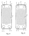
Figs. 4 and 5 disclose highly schematic examples of first and second heat exchanger plates of a plate heat exchanger. -
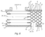
Fig. 6 discloses a first embodiment of a highly schematic cross section of a plate package of a plate heat exchanger exemplifying different positions of through holes. -
Fig. 7a-7d schematically discloses the formation of a through hole during thermal drilling and subsequent thermal tapping. -
Fig. 8 discloses a schematic cross section of a through hole made by thermal drilling. -
Figs. 1 to 3 disclose a typical example of a plate heat exchanger 1. The plate heat exchanger 1 includes a plate package P, which is formed by a number of compression molded heat exchanger plates A, B, which are provided side by side of each other to thereby form astack 2. The heat exchanger plates included in the embodiment are two different heat exchanger plates, which in the following are called the first heat exchanger plates A, seeFigs. 3 ,4 and6 , and the second heat exchanger plate B, seeFigs. 3 ,5 and6 . The plate package P includes substantially the same number of first heat exchanger plates A and second heat exchanger plates B. - As is clear from
Fig. 3 , the heat exchanger plates A, B are provided side by side in such a way that afirst plate interspace 3 is formed between each pair of adjacent first heat exchanger plates A and second heat exchanger plates B, and asecond plate interspace 4 between each pair of adjacent second heat exchanger plates B and first heat exchanger plates A. Every second plate interspace thus forms a respectivefirst plate interspace 3 and the remaining plate interspaces form a respectivesecond plate interspace 4, i. e. the first and second plate interspaces 3 and 4 are provided in an alternating order in the plate package P. Furthermore, the first and second plate interspaces 3 and 4 are substantially completely separated from each other. - A plurality of
compartments 5 are thus formed inside the plate package P. By way of example, afirst compartment 51 is formed at least partly by any of the first plate interspaces 3 and asecond compartment 52 is formed at least partly by any of the second plate interspaces 4. - The plate package P also includes an
upper end plate 6 and alower end plate 7, which are provided on a respective side of the plate package P. - The plate heat exchanger 1 may advantageously be adapted to operate as an evaporator in a cooling agent circuit, not disclosed. In such an evaporator application, the first plate interspaces 3 may form passages for a first fluid, such as a cooling agent, whereas the second plate interspaces 4 may form passages for a second fluid, which is adapted to be cooled by the cooling agent.
- In the embodiment disclosed in
Fig. 1 andFig. 3 , the heat exchanger plates A, B and the upper andlower end plates - As appears from especially
Figs. 2 ,4 and 5 , substantially each heat exchanger plate A, B has fourportholes 8, namely afirst porthole 8, asecond porthole 8, athird porthole 8 and afourth porthole 8. Thefirst portholes 8 form afirst inlet channel 9 to the first plate interspaces 3, which extends through substantially the whole plate package P, i. e. all plates A, B and also theupper end plate 6. Thesecond portholes 5 form afirst outlet channel 10 from the first plate interspaces 3, which also extends through substantially the whole plate package P, i. e. all plates A, B and theupper end plate 6. Thethird portholes 5 form asecond inlet channel 11 to the second plate interspaces 4, and thefourth portholes 5 form asecond outlet channel 12 from the second plate interspaces 4. Also these twochannels upper end plate 6. - In the disclosed embodiment, the
first inlet channel 9 being in communication with the first plate interspaces 3 may be seen as a part of thefirst compartment 51. Thefirst outlet channel 10, being in communication with the first plate interspaces 3, may also be seen as forming part of thefirst compartment 51. Likewise in the disclosed embodiment, thesecond inlet channel 11 being in communication with the second plate interspaces 4 may be seen as a part of thesecond compartment 52. Thesecond outlet channel 12, being in communication with the second plate interspaces 4, may also be seen as forming part of thesecond compartment 52. - In this type of prior art plate heat exchangers the
first plate interspace 3 is accessed via thefirst inlet channel 9 or thefirst outlet channel 10, i.e. via thefirst compartment 51. Likewise, thesecond plate interspace 4 is accessed via thesecond inlet channel 11 or thesecond outlet channel 12, i.e. via thesecond compartment 52. - In a prior art plate heat exchanger, any instruments, sensors or the like are inserted via one of these
channels - Now, for better understanding of the invention, reference will be made to
Fig. 6 disclosing a schematic cross section of aninlet channel 9; 11 or anoutlet channel 10; 12 of a typical plate heat exchanger 1 describing one embodiment of the invention. Although the cross section is restricted to the area in and around an inlet oroutlet channel 9; 10; 11; 12, the same principle is applicable to any exterior wall portion of the plate package P of a plate heat exchanger 1. -
Fig. 6 discloses a plurality of first and second heat exchanger plates A, B provided side by side in such a way that afirst plate interspace 3 is formed between each pair of adjacent first heat exchanger plates A and second heat exchanger plates B, and asecond plate interspace 4 between each pair of adjacent second heat exchanger plates B and first heat exchanger plates A. Every second plate interspace thus forms a respectivefirst plate interspace 3 and the remaining plate interspaces form a respectivesecond plate interspace 4, i. e. the first and second plate interspaces 3 and 4 are provided in an alternating order in the plate package P. Furthermore, the first and second plate interspaces 3 and 4 are substantially completely separated from each other. - The
circumferential side wall 13 of the plate package P comprises a plurality of outwardly extendingflanges 14, eachflange 14 being formed by the outerperipheral edge portion 15 of a pair of adjacent first heat exchanger plates A and second heat exchanger plates B. Thecircumferential side wall 13 extends essentially perpendicular to ageneral plane 16 of the first and the second heat exchanger plates A, B. - In the disclosed embodiment a plurality of through
holes 20 are arranged in thecircumferential side wall 13 of the plate package P. The through holes 20 are made by thermal drilling. Thermal drilling as a method will be described below. The longitudinal axis L of each throughhole 20 is arranged to extend essentially in parallel with thegeneral plane 16 of the first and the second heat exchanger plates A, B. - In the disclosed embodiment, each
first plate interspace 3 comprises a throughhole 20 extending from the exterior of the plate package P into the through channel being aninlet channel 9; 11 or anoutlet channel 10; 12. It is to be understood that other hole patterns than that illustrated may be used. Further, it is to be understood that by thermal drilling, the throughhole 20 may be arranged in any arbitrary position along thecircumferential side wall 13 of the plate package P. - In the disclosed embodiment, the through
holes 20 are arranged with their longitudinal axis L somewhat displaced from theadjacent flanges 14, whereby the throughholes 20 are essentially made through a portion of either of the first or the second heat exchanger plates A, B which together form a pair of heat exchanger plates A, B. It is to be understood that other positions are possible. - It is to be understood that the
circumferential side wall 13 of the plate package P may be essentially smooth. This may be made e.g. by bending the plurality of outwardly extendingflanges 14 to extend essentially in parallel with thecircumferential wall portion 13 or by cutting off theflanges 14. It is also to be understood that the cross section depends on thesurface pattern 21 of the heat exchanger plates A, B constituting the plate package P. - Further in
Fig. 6 , a throughhole 20 is arranged in theupper end plate 6, whereby a communication is made possible from the exterior of the plate package P to theplate interspace 3; 4 closest to theupper end plate 6. In the disclosed embodiment, the throughhole 20 extends into afirst plate interspace 3, i.e. thefirst compartment 51. Any arbitrary position is possible depending on the intended use of the throughhole 20. The same principle is applicable to thelower end plate 7. -
Fig. 6 also discloses a throughhole 20 arranged in thelower end plate 7. The throughhole 20 extends past theplate interspace 3; 4 closest to thelower end plate 7 and into the second,subsequent plate interspace 3; 4. In the disclosed embodiment, the longitudinal axis L of the throughhole 20 extends through a joint 22 between the two joined heat exchanger plates A, B. It is to be understood that other positions are possible. - Further,
Fig. 6 discloses one embodiment of a throughhole 20 having a diameter that provides access to more than one first orsecond plate interspace hole 23 is disclosed with an area extending across a plurality of heat exchanger plates A, B and thereby thepartition walls 24 between two orseveral plate interspaces partition walls 24 are formed by the heat exchanger plates A, B as such. - Thermal drilling, also known as flow drilling, friction drilling or form drilling is a non-cutting method used to form a hole. The hole may be a through hole or a blind hole. The process is illustrated in
Figs. 7a-7c . The thermal drilling provides a plastic re-shaping of the material. Thehole 20 is formed by rotating a pin-like tool 30 having a circular cross section with a diameter essentially corresponding to the hole to be formed, seeFig. 7a . Thetool 30 has a cone shapedfree end 31 engaging abase material 32 with a high rotational speed and with a relatively high axial pressure to thereby form ahole 20. Thetool 30 may be made by way of example carbide, such as Wolfram carbide. During rotation, thetool 30 creates a hole, see Fig. 9b by relying on the friction that results from the high rotational speed. The generated heat makes thebase material 32 malleable enough to be formed and perforated. As thetool 30 advances in the axial direction a material displacement occurs, seeFig. 7c . Initially the displaced material flows upwards towards the tool. As the tip of thefree end 31 of thetool 30 penetrates thelower surface 33 of thebase material 32, the displaced material starts to flow in the direction of the tool feed. As the material softens, the axial force is reduced and the feed rate is increased. Some displaced material may form acollar 34 around theupper surface 35 of thebase material 32. The rest of the material forms asleeve 36 in thelower surface 33. Thecollar 34 and thesleeve 36 will be coaxial with the resulting throughhole 20 and have a longitudinal extension L slightly exceeding the thickness of thebase material 32. The degree of work hardening depends on the material. As a result, the formedsleeve 36 is remarkably strong and may by way of example be threaded in a separate process, seeFig. 7d . The threading may be made either internally or externally of thesleeve 36. It is to be understood that the threading 37 may be limited to a portion of thecollar 34, thebase material 32 and thesleeve 36. - Standard drilling, NC, and CNC machines are all suitable for thermal drilling. But the process depends on the speed and force with which the
specialized tool 30 engages thebase material 32. It is to be understood that parameters such as hole size, material, and thickness all influence the suitable rotational speed, feed rate, and axial force. For example, thin materials may bend or collapse under excessive pressure, necessitating adequate support to prevent deformation. Predrilled holes may reduce the required axial force and also leave a smooth finish in the sleeve's lower edge. However, due to chipformation, predrilling is normally not an option when applied to heat exchangers. By thermal drilling being a non-cutting method no chips are formed that might fall into and contaminate the plate heat exchanger, such as a permanently joined plate package, or any devices to be arranged downstream such plate heat exchanger. Thermal drilling has surprisingly proven to be excellent to when makinglarge holes 23 having diameters straddling a plurality ofplate interspaces - Provided the
sleeve 36 is to be threaded, this may be made by using thermal tapping, basically using the same principle as with thermal drilling with the essential difference that the temperatures are much lower. Thermal tapping provides a plastic re-shaping of the material. The usedtool 38, seeFig. 7d , hasthreads 38a and when inserted into thehole 20 during rotation, the material in the envelope surface of the hole flows into the thread depression and thecrest 38a of thetool 38. Thus, the threads are cold formed leaving no chips. It is to be understood that the thread form, the depth and the strength is decided by the electedtool 38. It is also to be understood that the treading may be made by a non-cutting conventional plastic cold forming. - Now turning to
Fig. 8 , a schematic cross section of a throughhole 20 made by thermal drilling is disclosed. As a consequence of thermal drilling being a plastic re-shaping method in which thehole 30 is formed by displacing material instead of cutting material, themouth 39 of the throughhole 20 intended to face away from theplate interspace 3; 4 may comprise thecircumferential collar 34 of displaced material. It is possible to shape thecollar 34 by thetool 30 used during the thermal drilling to control the shape of thecollar 34. Further, the throughhole 20 comprises on its lower side a longitudinal envelope surface defining thesleeve 36 having a longitudinal extension being coaxial with the longitudinal axis L of the throughhole 20. Thesleeve 36 has afree edge portion 40. Also thesleeve 36 is the result of the thermal drilling being a plastic re-shaping method. The throughhole 20 may be threaded. The threading may be made along the fullinterior envelope surface 41 of the throughhole 20, i.e. from the outer edge of thecollar 34 to thefree edge portion 40 of thesleeve 36. Alternatively, only a portion of theenvelope surface 41 be threaded. It is to be understood that thecollar 34 may be used as connecting surface for any device, or for brackets or the like. - The through holes 20 may be used to receive or mount different types of sensors (not disclosed) such as temperature sensors, pressure sensors and optic sensors. The through holes 20 may also be used to mount plugs (not disclosed), such as drainage plugs or inspection glasses. Typical drainage plugs are drainage plugs for compressor oil and drainage plugs for system evacuation. The through holes 20 may also be used as separate inlets or outlets (not disclosed) for reversed cooling/heating duties.
- The invention has generally been described based on a plate heat exchanger 1 having first and second plate interspaces 3; 4 and four
port holes 8 allowing a flow of two fluids. It is to be understood that the invention is applicable also for plate heat exchangers having different configurations in terms of the number of plate interspaces, the number of port holes and the number of fluids to be handled. The invention is even applicable to plate heat exchangers wherein one or several inlet or outlet channels formed as through holes integrated in the heat exchanger plates are omitted. It is further to be understood that the invention is applicable no matter type of heat exchanger. It may by way of example be applied to heat exchangers of the tube and shell type or spiral heat exchangers. - The four
portholes 8 are in the disclosed embodiment provided in the proximity of a respective corner of the substantially rectangular heat exchanger plates A, B. It is to be understood that other positions are possible, and the invention should not be limited to the illustrated and disclosed positions. - The invention is also applicable to plate heat exchangers (not disclosed) comprising pairwise permanently joined heat exchanger plates, wherein each pair forms a cassette. In such solution, gaskets are arranged between each cassette. Also, in such embodiment, the heat exchanger plates forming each cassette may be permanently joined by welding. The invention is also applicable to plate heat exchangers (not disclosed) where the plate package is kept together by tie-bolts extending through the heat exchanger plates and the upper and lower end plates. In the latter case gaskets are used between the heat exchanger plates.
- The invention is not limited to the embodiment disclosed but may be varied and modified within the scope of the following claims, which partly has been described above.
Claims (14)
- A plate heat exchanger (1) including a plate package (P), which plate package includes a plurality of heat exchanger plates (A, B) of at least two configurations which are joined to each other and which alternate with each other to form a stack (2) of heat exchanger plates (A, B) forming plate interspaces (3, 4) between the heat exchanger plates (A, B), the plate interspaces (3, 4) being arranged to receive at least two different fluids, characterized in that at least one through hole (20) is arranged to extend between the exterior of the plate package (P) and a compartment (5) inside the plate package (P), the compartment (5) being at least partly formed by any of the plate interspaces (3, 4), wherein the at least one through hole (20) is formed by a thermal drilling.
- A plate heat exchanger according to claim 1, wherein the compartment (5) comprises a plurality of plate interspaces (3, 4) communicating with each other via a common channel (9; 10; 11; 12), wherein the at least one through hole (20) is arranged in a wall portion defining the common channel (9; 10; 11; 12).
- A plate heat exchanger according to any of the preceding claims, wherein said at least one through hole (20) is arranged to receive a component contained in the group consisting of sensors such as temperature sensors, pressure sensors and optic sensors, plugs, such as drainage plugs or inspection glasses and connectors for tubings.
- A plate heat exchanger according to any of the preceding claims, wherein the longitudinal axis (L) of the at least one through hole (20) is arranged to extend essentially in parallel with a general plane (16) of the longitudinal surface extension of the heat exchanger plates (A, B).
- A plate heat exchanger according to any of the preceding claims, wherein the at least one through hole (20) is arranged in a wall portion defining a circumferential side wall (13) of the plate package (P), the side wall extending essentially perpendicular to a general plane (16) of the longitudinal surface extension of the heat exchanger plates (A, B).
- A plate heat exchanger according to any of the preceding claims, wherein the at least one through hole (20) has a diameter providing access to more than one plate interspace (3, 4).
- A plate heat exchanger according to any of claims 1-6, wherein the at least one through hole is arranged in an upper or a lower end plate (6, 7) forming part of the plate package (P).
- A plate heat exchanger according to any of the preceding claims, wherein the heat exchanger plates (A, B) in the plate package (P) are permanently joined through brazing, welding, adhesive or bonding.
- A plate heat exchanger according to any of the preceding claims, wherein the at least one through hole (20) comprises a longitudinal envelope surface (41) defining a sleeve (36) having a longitudinal extension being coaxial with the longitudinal axis (L) of the through hole (20) and the sleeve having a free edge portion (40) facing the interior of the compartment (5).
- A plate heat exchanger according to any of the preceding claims, wherein the mouth (39) of the at least one through hole (20) facing away from the compartment (5) comprises a circumferential collar (34) formed during the thermal drilling.
- A plate heat exchanger according to any of the preceding claims, wherein the at least one through hole (20) comprises a threaded portion (37).
- A plate heat exchanger according to any of the preceding claims, further comprising a bracket arranged in or around the mouth of the at least one through hole.
- A plate heat exchanger according to claim 1, wherein the stack (2) of the plate package (P) includes a number of first heat exchanger plates (A) and a number of second heat exchanger plates (B), which are joined to each other and arranged side by side in such a way that a first plate interspace (3) is formed between each pair of adjacent first heat exchanger plates (A) and second heat exchanger plates (B), and a second plate interspace (4) is formed between each pair of adjacent second heat exchanger plates (B) and first heat exchanger plates (A), wherein the first plate interspaces (3) and the second plate interspaces (4) are separated from each other and provided side by side in an alternating order in the at least one plate package (P).
- A method of providing a through hole (20) in a plate heat exchanger (1), the method comprising
providing a plate heat exchanger (1) comprising a plate package (P), which plate package includes a plurality of heat exchanger plates (A, B) of at least two configurations which are joined to each other and which alternate with each other to form a stack (2) of heat exchanger plates forming plate interspaces (3, 4) between the heat exchanger plates (A, B), the plate interspaces (3, 4) being arranged to receive at least two different fluids, and
arranging by thermal drilling at least one through hole (20) extending between the exterior of the plate package (P) and a compartment (5) inside the plate package (P), the compartment (5) being at least partly formed by any of the plate interspaces (3, 4).
Priority Applications (8)
| Application Number | Priority Date | Filing Date | Title |
|---|---|---|---|
| EP12171915.7A EP2674715A1 (en) | 2012-06-14 | 2012-06-14 | A plate heat exchanger with thermally drilled hole |
| JP2015516583A JP2015519535A (en) | 2012-06-14 | 2013-06-11 | Plate heat exchanger with holes drilled |
| CN201380030937.7A CN104350350A (en) | 2012-06-14 | 2013-06-11 | Plate heat exchanger with thermal drilling |
| KR1020157000542A KR20150030235A (en) | 2012-06-14 | 2013-06-11 | A plate heat exchanger with thermally drilled hole |
| KR1020177004194A KR20170020937A (en) | 2012-06-14 | 2013-06-11 | A plate heat exchanger with thermally drilled hole |
| US14/407,555 US20150168075A1 (en) | 2012-06-14 | 2013-06-11 | Plate heat exchanger |
| PCT/EP2013/061982 WO2013186193A1 (en) | 2012-06-14 | 2013-06-11 | A plate heat exchanger with thermally drilled hole |
| TW102121014A TWI619920B (en) | 2012-06-14 | 2013-06-14 | A plate heat exchanger and the method of providing a through hole in such plate heat exchanger |
Applications Claiming Priority (1)
| Application Number | Priority Date | Filing Date | Title |
|---|---|---|---|
| EP12171915.7A EP2674715A1 (en) | 2012-06-14 | 2012-06-14 | A plate heat exchanger with thermally drilled hole |
Publications (1)
| Publication Number | Publication Date |
|---|---|
| EP2674715A1 true EP2674715A1 (en) | 2013-12-18 |
Family
ID=48672583
Family Applications (1)
| Application Number | Title | Priority Date | Filing Date |
|---|---|---|---|
| EP12171915.7A Withdrawn EP2674715A1 (en) | 2012-06-14 | 2012-06-14 | A plate heat exchanger with thermally drilled hole |
Country Status (7)
| Country | Link |
|---|---|
| US (1) | US20150168075A1 (en) |
| EP (1) | EP2674715A1 (en) |
| JP (1) | JP2015519535A (en) |
| KR (2) | KR20170020937A (en) |
| CN (1) | CN104350350A (en) |
| TW (1) | TWI619920B (en) |
| WO (1) | WO2013186193A1 (en) |
Cited By (4)
| Publication number | Priority date | Publication date | Assignee | Title |
|---|---|---|---|---|
| CN106001662A (en) * | 2016-06-28 | 2016-10-12 | 洛阳红奇机械科技有限公司 | Manufacturing process for integrated water jacket heating plate of big-plate hot press |
| US9488210B2 (en) | 2014-09-30 | 2016-11-08 | Ford Global Technologies, Llc | Flow drill screw assembly and method |
| CN106575619A (en) * | 2014-08-01 | 2017-04-19 | 应用材料公司 | Multi-substrate thermal management apparatus |
| US11841195B2 (en) | 2016-12-16 | 2023-12-12 | Swep International Ab | Means for sensing temperature |
Families Citing this family (14)
| Publication number | Priority date | Publication date | Assignee | Title |
|---|---|---|---|---|
| EP2413045B1 (en) * | 2010-07-30 | 2014-02-26 | Grundfos Management A/S | Heat exchange unit |
| SI2674714T1 (en) | 2012-06-14 | 2019-11-29 | Alfa Laval Corp Ab | A plate heat exchanger with injection means |
| SI2674716T1 (en) | 2012-06-14 | 2015-08-31 | Alfa Laval Corporate Ab | A plate heat exchanger |
| KR101583921B1 (en) * | 2014-05-02 | 2016-01-11 | 현대자동차주식회사 | Method and apparatus for manufacturing heat exchanger for vehicle |
| EP3124907B1 (en) * | 2015-07-29 | 2019-04-10 | Zhejiang Sanhua Automotive Components Co., Ltd. | Heat exchange device |
| DE102017211529A1 (en) * | 2017-07-06 | 2019-01-10 | Mahle International Gmbh | Insert tube for the inlet channel of a plate heat exchanger |
| CN111684229A (en) * | 2017-12-14 | 2020-09-18 | 加拿大粉体流冷却科学公司 | Plate heat exchanger for heating or cooling solid particulate material |
| JP6887074B2 (en) * | 2018-03-05 | 2021-06-16 | パナソニックIpマネジメント株式会社 | Heat exchanger |
| US12044487B2 (en) | 2018-03-27 | 2024-07-23 | Lg Electronics Inc. | Plate-type heat exchanger and a method for manufacturing same |
| KR102115924B1 (en) * | 2018-03-27 | 2020-05-27 | 엘지전자 주식회사 | Plate type heat exchanger and a method for manufacturng the same |
| CN114270146A (en) * | 2019-08-23 | 2022-04-01 | 特兰特公司 | Sensor assembly for heat exchanger |
| JP2023522749A (en) * | 2020-04-23 | 2023-05-31 | アルファ-ラヴァル・コーポレート・アーベー | Heat exchanger including plate package and hollow manifold |
| DE102023201575A1 (en) * | 2022-06-10 | 2023-12-21 | Hanon Systems | Heat exchanger and method for producing a heat exchanger |
| MX2024008445A (en) * | 2023-08-07 | 2025-03-07 | Danfoss As | Plate heat exchanger. |
Citations (7)
| Publication number | Priority date | Publication date | Assignee | Title |
|---|---|---|---|---|
| EP0487007A2 (en) * | 1990-11-23 | 1992-05-27 | Guglielmo Wolfsgruber | Process for the manufacture of radiant panels and the like and radiant panel thus obtained |
| EP0677716A1 (en) * | 1994-04-12 | 1995-10-18 | Showa Aluminum Corporation | Stacked-type duplex heat exchanger |
| EP1066493A1 (en) * | 1998-04-02 | 2001-01-10 | Alfa Laval AB | Heat exchanger installation |
| EP1242782A1 (en) * | 1999-12-08 | 2002-09-25 | Alfa Laval AB | A heat exchanger arrangement and method for control of a fluid through a heat exchanger arrangement |
| US20030010017A1 (en) * | 2001-07-12 | 2003-01-16 | Myers Stephen J. | Catalytic converter with integral oxygen sensor |
| US20070160510A1 (en) * | 2001-07-12 | 2007-07-12 | Schultz Eric C | Gas sensor mounting boss and method of making |
| US20080257538A1 (en) * | 1997-02-25 | 2008-10-23 | Lars Persson | Heat Exchanger With Temperature-Controlled Valve |
Family Cites Families (24)
| Publication number | Priority date | Publication date | Assignee | Title |
|---|---|---|---|---|
| US1662236A (en) * | 1926-09-11 | 1928-03-13 | Edmund Mcgillivray | Steam and hot-water radiator |
| US3866674A (en) * | 1973-10-01 | 1975-02-18 | Gen Electric | Gas turbine regenerator |
| US3976128A (en) * | 1975-06-12 | 1976-08-24 | Ford Motor Company | Plate and fin heat exchanger |
| JPS55160722U (en) * | 1979-05-07 | 1980-11-18 | ||
| JPS58157545A (en) * | 1982-03-06 | 1983-09-19 | フロ−ドリル・ベ−・ハウ | Fluid drill for tabular material |
| JPS59139771U (en) * | 1983-03-08 | 1984-09-18 | 三菱電機株式会社 | heat exchange equipment |
| JP2850587B2 (en) * | 1991-09-05 | 1999-01-27 | 松下電器産業株式会社 | Heat exchanger |
| JP3358250B2 (en) * | 1992-10-21 | 2002-12-16 | 株式会社デンソー | Refrigerant evaporator |
| TW249274B (en) * | 1993-10-08 | 1995-06-11 | Hitachi Seisakusyo Kk | Plate-type fluid passage device and method of producing same |
| SE9502189D0 (en) * | 1995-06-16 | 1995-06-16 | Tetra Laval Holdings & Finance | plate heat exchangers |
| JP3031232B2 (en) * | 1996-03-04 | 2000-04-10 | 松下電器産業株式会社 | Stacked heat exchanger for absorption heat pump |
| SE530957C2 (en) * | 2004-09-08 | 2008-11-04 | Ep Technology Ab | Heat exchanger with temperature controlled valve |
| SE518475C2 (en) * | 2001-02-20 | 2002-10-15 | Alfa Laval Ab | Flat heat exchanger with sensor device |
| FR2823995B1 (en) * | 2001-04-25 | 2008-06-06 | Alfa Laval Vicarb | IMPROVED DEVICE FOR EXCHANGING AND / OR REACTING BETWEEN FLUIDS |
| EP1707912A1 (en) * | 2005-04-01 | 2006-10-04 | Fiwihex B.V. | Heat exchanger and greenhouse |
| US7597137B2 (en) * | 2007-02-28 | 2009-10-06 | Colmac Coil Manufacturing, Inc. | Heat exchanger system |
| WO2009062738A1 (en) * | 2007-11-14 | 2009-05-22 | Swep International Ab | Distribution pipe |
| WO2010069872A1 (en) * | 2008-12-17 | 2010-06-24 | Swep International Ab | Port opening of heat exchanger |
| JP2010223571A (en) * | 2009-02-27 | 2010-10-07 | Hitachi Appliances Inc | Air conditioner, flow drill for forming tube seat of air conditioner refrigerant quantity regulator, and tube seat processing method |
| CN101788243B (en) * | 2009-04-03 | 2011-09-28 | 三花丹佛斯(杭州)微通道换热器有限公司 | Refrigerant distributor for heat exchanger and heat exchanger |
| DE102009052489A1 (en) * | 2009-04-29 | 2010-11-11 | Siemens Aktiengesellschaft | Apparatus for exchanging heat with a plate pack and method for its production |
| WO2011126488A2 (en) * | 2010-04-09 | 2011-10-13 | Ingersoll-Rand Company | Formed microchannel heat exchanger |
| JP2012013108A (en) * | 2010-06-29 | 2012-01-19 | Hitachi Appliances Inc | Method for manufacturing pipe seat and air conditioner |
| JP5710232B2 (en) * | 2010-12-09 | 2015-04-30 | 株式会社日阪製作所 | Plate heat exchanger |
-
2012
- 2012-06-14 EP EP12171915.7A patent/EP2674715A1/en not_active Withdrawn
-
2013
- 2013-06-11 KR KR1020177004194A patent/KR20170020937A/en not_active Withdrawn
- 2013-06-11 JP JP2015516583A patent/JP2015519535A/en active Pending
- 2013-06-11 WO PCT/EP2013/061982 patent/WO2013186193A1/en not_active Ceased
- 2013-06-11 US US14/407,555 patent/US20150168075A1/en not_active Abandoned
- 2013-06-11 CN CN201380030937.7A patent/CN104350350A/en active Pending
- 2013-06-11 KR KR1020157000542A patent/KR20150030235A/en not_active Ceased
- 2013-06-14 TW TW102121014A patent/TWI619920B/en active
Patent Citations (7)
| Publication number | Priority date | Publication date | Assignee | Title |
|---|---|---|---|---|
| EP0487007A2 (en) * | 1990-11-23 | 1992-05-27 | Guglielmo Wolfsgruber | Process for the manufacture of radiant panels and the like and radiant panel thus obtained |
| EP0677716A1 (en) * | 1994-04-12 | 1995-10-18 | Showa Aluminum Corporation | Stacked-type duplex heat exchanger |
| US20080257538A1 (en) * | 1997-02-25 | 2008-10-23 | Lars Persson | Heat Exchanger With Temperature-Controlled Valve |
| EP1066493A1 (en) * | 1998-04-02 | 2001-01-10 | Alfa Laval AB | Heat exchanger installation |
| EP1242782A1 (en) * | 1999-12-08 | 2002-09-25 | Alfa Laval AB | A heat exchanger arrangement and method for control of a fluid through a heat exchanger arrangement |
| US20030010017A1 (en) * | 2001-07-12 | 2003-01-16 | Myers Stephen J. | Catalytic converter with integral oxygen sensor |
| US20070160510A1 (en) * | 2001-07-12 | 2007-07-12 | Schultz Eric C | Gas sensor mounting boss and method of making |
Non-Patent Citations (2)
| Title |
|---|
| "Bohren, wo es am duennsten ist", WERKSTATT UND BETRIEB, CARL HANSER VERLAG GMBH & CO. KG, DE, vol. 141, no. 10, 1 October 2008 (2008-10-01), pages 104 - 105, XP001517648, ISSN: 0043-2792 * |
| DALE JOHNSON: "Let the revolution begin", INTERNET CITATION, 3 January 2004 (2004-01-03), XP002424482, Retrieved from the Internet <URL:http://www.fandmmag.com/fmmag/article_archives.asp?action=details&magarticle_id=404&channel_id=10&mag_id=5> [retrieved on 20070313] * |
Cited By (5)
| Publication number | Priority date | Publication date | Assignee | Title |
|---|---|---|---|---|
| CN106575619A (en) * | 2014-08-01 | 2017-04-19 | 应用材料公司 | Multi-substrate thermal management apparatus |
| CN106575619B (en) * | 2014-08-01 | 2020-07-24 | 应用材料公司 | Multi-substrate thermal management equipment |
| US9488210B2 (en) | 2014-09-30 | 2016-11-08 | Ford Global Technologies, Llc | Flow drill screw assembly and method |
| CN106001662A (en) * | 2016-06-28 | 2016-10-12 | 洛阳红奇机械科技有限公司 | Manufacturing process for integrated water jacket heating plate of big-plate hot press |
| US11841195B2 (en) | 2016-12-16 | 2023-12-12 | Swep International Ab | Means for sensing temperature |
Also Published As
| Publication number | Publication date |
|---|---|
| CN104350350A (en) | 2015-02-11 |
| WO2013186193A1 (en) | 2013-12-19 |
| KR20170020937A (en) | 2017-02-24 |
| TWI619920B (en) | 2018-04-01 |
| JP2015519535A (en) | 2015-07-09 |
| KR20150030235A (en) | 2015-03-19 |
| US20150168075A1 (en) | 2015-06-18 |
| TW201405085A (en) | 2014-02-01 |
Similar Documents
| Publication | Publication Date | Title |
|---|---|---|
| US20150168075A1 (en) | Plate heat exchanger | |
| EP2345861B1 (en) | Heat exchanger with extruded multi-chamber manifold with machined bypass | |
| EP2342521B1 (en) | Heat exchanger | |
| US10837720B2 (en) | Heat exchanger with aluminum tubes rolled into an aluminum tube support | |
| EP2863159A1 (en) | Heat exchanger, method for producing same, and refrigeration cycle device | |
| WO2009104575A1 (en) | Method of manufacturing a pipe coupling component, method of manufacturing a casing structural member, and pipe coupling structure for a hollow part | |
| JP4262779B2 (en) | Heat transfer plate manufacturing method, heat transfer plate assembly, and plate heat exchanger comprising heat transfer plate assembly | |
| JP2019168190A (en) | Metal laminate and method of manufacturing metal laminate | |
| US20180252475A1 (en) | Heat exchange tube for heat exchanger, heat exchanger and assembly method thereof | |
| KR101359778B1 (en) | Welding method for shell and tube | |
| WO2006014956A1 (en) | Heat exchano'er having a double baffle | |
| US6540016B1 (en) | Method of forming heat exchanger tube ports and manifold therefor | |
| WO2019021457A1 (en) | Refrigerant distributor and heat pump device having said refrigerant distributor | |
| EP2997322B1 (en) | Method for manufacturing a multiple manifold assembly having internal communication ports | |
| JP6455103B2 (en) | Heat exchanger | |
| KR101723874B1 (en) | Multifid Metal Plate and Heat Exchanger with Injection Flow Part | |
| CN114929903B (en) | Cooling plate for metallurgical furnace | |
| JP6263922B2 (en) | Heat exchanger | |
| EP1087851A1 (en) | A method of producing a plate heat exchanger; and a plate heat exchanger | |
| KR20160117376A (en) | Manufacturing method for heat exchanger with i-o pipe connecting member for heat exchanger | |
| JP2008232566A (en) | Method of forming connector part for heat exchanger | |
| KR101694671B1 (en) | Manufacturing method for heat exchanger with i-o pipe connecting member for heat exchanger | |
| KR100740699B1 (en) | Heat exchanger header pipe | |
| KR101694670B1 (en) | I-o pipe connecting member for heat exchanger | |
| CN100476336C (en) | Heat exchanger and method for manufacturing the same |
Legal Events
| Date | Code | Title | Description |
|---|---|---|---|
| PUAI | Public reference made under article 153(3) epc to a published international application that has entered the european phase |
Free format text: ORIGINAL CODE: 0009012 |
|
| AK | Designated contracting states |
Kind code of ref document: A1 Designated state(s): AL AT BE BG CH CY CZ DE DK EE ES FI FR GB GR HR HU IE IS IT LI LT LU LV MC MK MT NL NO PL PT RO RS SE SI SK SM TR |
|
| AX | Request for extension of the european patent |
Extension state: BA ME |
|
| 17P | Request for examination filed |
Effective date: 20140313 |
|
| RBV | Designated contracting states (corrected) |
Designated state(s): AL AT BE BG CH CY CZ DE DK EE ES FI FR GB GR HR HU IE IS IT LI LT LU LV MC MK MT NL NO PL PT RO RS SE SI SK SM TR |
|
| STAA | Information on the status of an ep patent application or granted ep patent |
Free format text: STATUS: THE APPLICATION HAS BEEN WITHDRAWN |
|
| 18W | Application withdrawn |
Effective date: 20180426 |