EP2674703B1 - Refrigerator - Google Patents
Refrigerator Download PDFInfo
- Publication number
- EP2674703B1 EP2674703B1 EP13171366.1A EP13171366A EP2674703B1 EP 2674703 B1 EP2674703 B1 EP 2674703B1 EP 13171366 A EP13171366 A EP 13171366A EP 2674703 B1 EP2674703 B1 EP 2674703B1
- Authority
- EP
- European Patent Office
- Prior art keywords
- ice
- stopper
- chute
- refrigerating compartment
- bank
- Prior art date
- Legal status (The legal status is an assumption and is not a legal conclusion. Google has not performed a legal analysis and makes no representation as to the accuracy of the status listed.)
- Active
Links
Images


Classifications
-
- F—MECHANICAL ENGINEERING; LIGHTING; HEATING; WEAPONS; BLASTING
- F25—REFRIGERATION OR COOLING; COMBINED HEATING AND REFRIGERATION SYSTEMS; HEAT PUMP SYSTEMS; MANUFACTURE OR STORAGE OF ICE; LIQUEFACTION SOLIDIFICATION OF GASES
- F25C—PRODUCING, WORKING OR HANDLING ICE
- F25C5/00—Working or handling ice
- F25C5/20—Distributing ice
-
- F—MECHANICAL ENGINEERING; LIGHTING; HEATING; WEAPONS; BLASTING
- F25—REFRIGERATION OR COOLING; COMBINED HEATING AND REFRIGERATION SYSTEMS; HEAT PUMP SYSTEMS; MANUFACTURE OR STORAGE OF ICE; LIQUEFACTION SOLIDIFICATION OF GASES
- F25C—PRODUCING, WORKING OR HANDLING ICE
- F25C1/00—Producing ice
- F25C1/22—Construction of moulds; Filling devices for moulds
- F25C1/24—Construction of moulds; Filling devices for moulds for refrigerators, e.g. freezing trays
-
- F—MECHANICAL ENGINEERING; LIGHTING; HEATING; WEAPONS; BLASTING
- F25—REFRIGERATION OR COOLING; COMBINED HEATING AND REFRIGERATION SYSTEMS; HEAT PUMP SYSTEMS; MANUFACTURE OR STORAGE OF ICE; LIQUEFACTION SOLIDIFICATION OF GASES
- F25C—PRODUCING, WORKING OR HANDLING ICE
- F25C5/00—Working or handling ice
- F25C5/02—Apparatus for disintegrating, removing or harvesting ice
-
- F—MECHANICAL ENGINEERING; LIGHTING; HEATING; WEAPONS; BLASTING
- F25—REFRIGERATION OR COOLING; COMBINED HEATING AND REFRIGERATION SYSTEMS; HEAT PUMP SYSTEMS; MANUFACTURE OR STORAGE OF ICE; LIQUEFACTION SOLIDIFICATION OF GASES
- F25C—PRODUCING, WORKING OR HANDLING ICE
- F25C5/00—Working or handling ice
- F25C5/18—Storing ice
-
- F—MECHANICAL ENGINEERING; LIGHTING; HEATING; WEAPONS; BLASTING
- F25—REFRIGERATION OR COOLING; COMBINED HEATING AND REFRIGERATION SYSTEMS; HEAT PUMP SYSTEMS; MANUFACTURE OR STORAGE OF ICE; LIQUEFACTION SOLIDIFICATION OF GASES
- F25C—PRODUCING, WORKING OR HANDLING ICE
- F25C5/00—Working or handling ice
- F25C5/20—Distributing ice
- F25C5/22—Distributing ice particularly adapted for household refrigerators
-
- F—MECHANICAL ENGINEERING; LIGHTING; HEATING; WEAPONS; BLASTING
- F25—REFRIGERATION OR COOLING; COMBINED HEATING AND REFRIGERATION SYSTEMS; HEAT PUMP SYSTEMS; MANUFACTURE OR STORAGE OF ICE; LIQUEFACTION SOLIDIFICATION OF GASES
- F25D—REFRIGERATORS; COLD ROOMS; ICE-BOXES; COOLING OR FREEZING APPARATUS NOT OTHERWISE PROVIDED FOR
- F25D23/00—General constructional features
- F25D23/02—Doors; Covers
-
- F—MECHANICAL ENGINEERING; LIGHTING; HEATING; WEAPONS; BLASTING
- F25—REFRIGERATION OR COOLING; COMBINED HEATING AND REFRIGERATION SYSTEMS; HEAT PUMP SYSTEMS; MANUFACTURE OR STORAGE OF ICE; LIQUEFACTION SOLIDIFICATION OF GASES
- F25D—REFRIGERATORS; COLD ROOMS; ICE-BOXES; COOLING OR FREEZING APPARATUS NOT OTHERWISE PROVIDED FOR
- F25D11/00—Self-contained movable devices, e.g. domestic refrigerators
- F25D11/02—Self-contained movable devices, e.g. domestic refrigerators with cooling compartments at different temperatures
Definitions
- the present disclosure relates to a refrigerator.
- refrigerators are home appliances for storing foods at a low temperature in an inner storage space covered by a door. That is, since such a refrigerator cools the inside of a storage space by using cool air generated through heat-exchange with a refrigerant circulating a refrigeration cycle, foods stored in the storage space may be stored in an state that slows spoilage.
- an ice maker for making ice may be provided inside the refrigerator.
- the ice maker is configured so that water supplied from a water supply source or a water tank is accommodated into an ice tray to make ice pieces.
- a dispenser for dispensing purified water or ice made in the ice maker to the outside may be provided in the refrigerating compartment door.
- US 2012/0023999 A1 relates to a refrigerator having an ice transfer unit, wherein the refrigerator includes: a refrigerator main body including a freezing chamber positioned at a lower portion thereof and a refrigerating chamber positioned at an upper portion thereof; an ice maker and an ice bank positioned at an inner side of the freezing chamber; an ice dispenser positioned at an inner side of the refrigerating chamber; a transfer flow path extending from the ice bank to the ice dispenser; an ice input unit supplying ice stored in the ice bank to the interior of the transfer flow path; and a blower blowing air to allow the ice supplied to the interior of the ice transfer flow path toward the ice dispenser.
- a refrigerator main body including a freezing chamber positioned at a lower portion thereof and a refrigerating chamber positioned at an upper portion thereof; an ice maker and an ice bank positioned at an inner side of the freezing chamber; an ice dispenser positioned at an inner side of the refrigerating chamber; a transfer flow path extending from the
- KR 200 154 593 Y1 relates to an ice dispensing structure in refrigerators.
- EP 1 598 618 A1 relates to a refrigerator, wherein the refrigerator is provided with an airflow passage for an ice making compartment of the refrigerator.
- a main body has an opened side, and a door selectively closes the opened side of the main body.
- An ice making compartment is formed in the door, the ice making compartment being insulated from the outside and being kept at a low temperature.
- a duct is formed in the main body for exchanging cooling air with the ice making compartment, and a cooling air passage is formed at an outer surface of the ice making compartment to connect the duct with the ice making compartment.
- a switching unit closes the cooling air passage when the door is opened, and opens the cooling air passage when the door is closed. With this arrangement, the cooling air can be sufficiently supplied to the ice making compartment without the penetration of foreign substance.
- a refrigerator includes a cabinet defining a refrigerating compartment and a freezing compartment, a refrigerating compartment door configured to open and close at least a portion of the refrigerating compartment, and an ice bank mounted on the refrigerating compartment door and configured to store ice therein.
- the refrigerator also includes a dispenser disposed under the ice bank and configured to dispense ice stored in the ice bank and an ice maker provided in the freezing compartment and configured to make ice.
- the refrigerator further includes a transfer member connected to the ice maker and configured to transfer ice made in the ice maker to the ice bank and an ice chute connecting an outlet of the transfer member to the ice bank.
- the ice chute defines an ice transfer passage between the transfer member and the ice bank.
- the refrigerator includes a stopper disposed on a discharge end of the ice chute and configured to block discharge of ice from the ice chute in a state in which the refrigerating compartment door is opened.
- the stopper may have a shape that covers the discharge end of the ice chute and may have a plurality of flaps defined by a plurality of cutoff lines that are arranged radially from a center of the stopper.
- the stopper may apply resistance to ice passing through the stopper and may bend to enable ice pushed with a sufficient amount of force to discharge.
- the stopper may be made of a flexible material that restores to its original position after ice passes therethrough.
- the stopper may be made of a silicon material.
- a cool air hole may be defined in a center of the stopper. The cool air hole may have a diameter that is less than a diameter of an ice piece that passes through the stopper.
- the stopper includes a damper configured to rotate to open and close at least a portion of the discharge end of the ice chute and the damper applies resistance to ice passing through the stopper, rotates to enable ice pushed with a sufficient amount of force to discharge through the stopper, and returns to its original position by a self-weight or a flexible material thereof or by a restoring force of a spring after the ice passes therethrough.
- a rotation shaft of the damper may be disposed above the discharge end of the ice chute.
- a spring may be coupled to a rotation shaft of the damper.
- the damper applies resistance to ice passing through the stopper, rotates to enable ice pushed with a sufficient amount of force to discharge through the stopper, and returns to its original position by a restoring force of the spring after the ice passes therethrough.
- the refrigerator may include a support member connecting the discharge end of the ice chute to the stopper and the stopper may be coupled to the support member.
- the stopper may be coupled to the discharge end of the ice chute.
- the stopper may be coupled to a sidewall of the refrigerating compartment corresponding to the discharge end of the ice chute.
- the ice maker may be configured to make spherical ice pieces.
- the ice maker may include an upper tray comprising a first recess part recessed in a hemispherical shape and a lower tray comprising a second recess part recessed in a hemispherical shape.
- the upper tray and the lower tray may be arranged such that the first recess part is recessed away from the lower tray and the second recess part is recessed away from the upper tray.
- a refrigerator in another aspect, includes a cabinet defining a freezing compartment therein, the cabinet having an open side.
- the refrigerator also includes a door configured to open and close to expose and cover at least a portion of the open side of the cabinet and an ice bank disposed on a back surface of the door and configured to store ice.
- the refrigerator further includes an ice maker disposed within the cabinet and configured to make ice, a transfer member connected to the ice maker and configured to transfer ice made in the ice maker to the ice bank, and an ice chute connecting an outlet of the transfer member to the ice bank.
- the ice chute defines an ice transfer passage between the transfer member and the ice bank.
- the refrigerator includes a stopper disposed on a discharge end of the ice chute and configured to interfere with discharge of ice from the ice chute.
- the stopper may include a front part disposed on the discharge end of the ice chute and a plurality of flaps defined by radial cuts made to the front part of the stopper.
- the plurality of flaps may bend toward an inside of the ice bank based on the transfer member transferring an ice piece to the ice bank through the stopper.
- the stopper may be detachably coupled to the discharge end of the ice chute. At least a portion of the stopper may be disposed within the ice bank in a state in which the door covers the open side of the cabinet.
- the ice maker may be configured to make spherical ice pieces.
- the ice maker may include an upper tray comprising a first recess part recessed in a hemispherical shape and a lower tray comprising a second recess part recessed in a hemispherical shape.
- the upper tray and the lower tray may be arranged such that the first recess part is recessed away from the lower tray and the second recess part is recessed away from the upper tray.
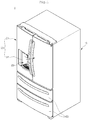
- Fig. 1 illustrates an example refrigerator.
- Fig. 2 is illustrates an example cool air circulation state within the inside of the refrigerator shown in FIG. 1 and an example ice making compartment in the refrigerator shown in FIG. 1 .
- a refrigerator 1 includes a cabinet 10 defining a storage space and doors 20 and 30 mounted on the cabinet 10.
- An outer appearance of the refrigerator 1 may be defined by the cabinet 10 and the doors 20 and 30.
- the storage space within the cabinet 10 is vertically partitioned by a barrier 11.
- a refrigerating compartment 12 is defined in the partitioned upper side, and a freezing compartment 13 is defined in the partitioned lower side.
- the doors 20 and 30 include a refrigerating compartment door 20 for opening or closing the refrigerating compartment 12 and a freezing compartment door 30 for opening or closing the freezing compartment 13.
- the refrigerating compartment door 20 includes a plurality of doors disposed on left and right sides thereof.
- the plurality of doors include a first refrigerating compartment door 21, and a second refrigerating compartment door 22 disposed at a right side of the first refrigerating compartment door 21.
- the first refrigerating compartment door 21 and the second refrigerating compartment door 22 are independently rotated with respect to each other.
- the freezing compartment door 30 may be provided as a slidably accessible door.
- the freezing compartment door 30 includes a plurality of doors that are vertically disposed.
- the freezing compartment door 30 may be provided as one door as needed.
- a dispenser 23 for dispensing water or ice is disposed in one of the first refrigerating compartment door 21 and the second refrigerating compartment door 22.
- a structure in which the dispenser 23 is disposed in the first refrigerating compartment door 21 is illustrated in Fig. 1 .
- An ice making compartment 40 for making and storing ice is defined in the first refrigerating compartment door 21.
- the ice making compartment 40 is provided as an independent insulation space.
- the ice making compartment 40 may be opened or closed by an ice making compartment door 41.
- An ice maker for making ice may be provided within the ice making compartment 40.
- components for storing made ice or dispensing the made ice through the dispenser 23 may be provided in the ice making compartment 40.
- a cool air inlet 42 and a cool air outlet 43 which communicate with a cool air duct 50 disposed in the cabinet 10 when the first refrigerating compartment door 21 is closed are provided in one surface of the ice making compartment 40. Cool air introduced into the cool air inlet 42 cools the inside of the ice making compartment 40 to make ice. Then, the heat-exchanged cool air is discharged to the outside of the ice making compartment 40 through the cool air outlet 43.
- a heat exchange chamber 14 partitioned from the freezing compartment 13 is defined in a rear side of the freezing compartment 13.
- An evaporator is provided in the heat exchange chamber 14. Cool air generated in the evaporator may be supplied into the freezing compartment 13, the refrigerating compartment 12, and the ice making compartment 40 to cool the inside of each of the freezing compartment 13, the refrigerating compartment 12, and the ice making compartment 40.
- the cool air duct 50 for supplying cool air into the ice making compartment 40 and recovering the cool air from the ice making compartment 40 is disposed in a side wall of the cabinet 10.
- the cool air duct 50 extends from a side of the freezing compartment 13 to an upper portion of the refrigerating compartment 12.
- the cool air duct 50 communicates with the cool air inlet 42 and the cool air outlet 43.
- the cool air duct 50 communicates with the heat exchange chamber 14 and the freezing compartment 13.
- cool air within the heat exchange chamber 14 is introduced into the ice making compartment 40 through a supply passage 51 of the cool air duct 50. Also, cool air within the ice making compartment 40 is recovered into the freezing compartment 13 through a recovery passage 52 of the cool air duct 50. Ice is made and stored within the ice making compartment 40 by continuous circulation of the cool air through the cool air duct 50.
- making and storage of ice is performed within the ice making compartment 40 provided in the refrigerating compartment 20, which increases a volume of the refrigerating compartment door 20.
- an accommodation space defined in a back surface of the refrigerating compartment door 20 may be reduced.
- Fig. 3 illustrates an example refrigerator with a door opened
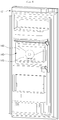
- Fig. 4 illustrates an example ice bank with a door opened
- Fig. 5 illustrates the inside of an example freezing compartment.
- a refrigerator 100 includes a cabinet 110 and a door.
- the cabinet 110 and the door define an outer appearance of the refrigerator 100.
- the inside of the cabinet 110 is partitioned by a barrier 111. That is, a refrigerating compartment 112 is defined at an upper side, and a freezing compartment 113 is defined at a lower side.
- An ice maker 200 for making ice and an ice transfer device 300 for transferring the made ice into an ice bank 140 may be provided within the freezing compartment 113.
- an ice chute 340 and a cool air duct 350 of the ice transfer device 300 have openings 341 and 351, respectively, defined in a sidewall of the refrigerating compartment 112.
- the opening 341 of the ice chute 340 may be called a "discharge end 341" because ice is discharged into the ice bank 140 from the ice chute 340 through the opening 341 of the ice chute 340.
- the door includes a refrigerating compartment door 120 for covering the refrigerating compartment 112 and a freezing compartment door 130 for covering the freezing compartment 113.
- the refrigerating compartment door 120 includes a first refrigerating compartment door 121 and a second refrigerating compartment door 122 which are rotated to open or close the refrigerating compartment 112.
- the freezing compartment door 130 may be slidably withdrawn in front and rear directions to open or close the freezing compartment 113.
- a dispenser 123 may be provided in a front surface of the first refrigerating compartment door 121. Purified water and ice made in the ice maker 200 may be dispensed to the outside through the dispenser 123.
- the ice bank 140 is provided in a back surface of the refrigerating compartment door 120.
- the ice bank 140 provides a space for storing ice transferred by the ice transfer device 300.
- the ice bank 140 may be openable by the first refrigerating compartment door 121.
- the ice bank 140 defines an insulation space.
- the ice bank 140 is connected to the ice chute 340 and the cool air duct 350 to allow ice to be supplied and cool air to be circulated.
- the ice bank 140 communicates with the dispenser 123.
- a separate case 142 for accommodating ice may be provided within the ice bank 140.
- an auger 143 configured to smoothly transfer ice and a blade for crushing ice to dispense ice pieces may be further provided within the ice bank 140.
- the ice bank 140 protrudes to contact an inner sidewall of the refrigerating compartment 112 when the first refrigerating compartment door 121 is closed.
- An air hole 144 and an ice inlet hole 145 may be further defined in a sidewall of the ice bank 140 corresponding to the openings 341 and 351 of the ice chute 340 and the cool air duct 350 which are disposed in the inner sidewall of the refrigerating compartment 112.
- a stopper (see reference numeral 400 of Fig. 9 ) is disposed on a side of the opening 341 of the ice chute 340.
- the stopper 400 may be a member for interfering with the ice transferred from the opening 341 of the ice chute 340 into the ice inlet hole 145.
- the ice transferred between the opening 341 of the ice chute 340 and the ice inlet hole 145 may stay between the stopper 400 and the ice chute 340 by the interference of the stopper 400.
- the stopper 400 prevents the ice from dropping down on the floor when the first refrigerating compartment door 121 is opened.
- a withdrawable drawer, the ice maker 200, and the ice transfer device 300 may be disposed inside the freezing compartment 113.
- the ice maker 200 is configured to make ice by using water supplied from the water supply source.
- the ice maker 200 may be disposed in a left upper side of the freezing compartment 113.
- the ice maker 200 is fixedly mounted on a bottom surface of the barrier 111.
- the ice made in the ice maker 200 may drop down and fall into a housing 310 of the ice transfer device 300.
- the ice transfer device 300 for supplying the ice made in the ice maker 200 into the ice bank 140 may be disposed under the ice maker 200. That is, the positions of the ice maker 200 and the ice transfer device 300 may be determined by the position of the ice bank 140.
- the ice maker 200 and the ice transfer device 300 may be disposed in a left upper side of the freezing compartment 113 so that each of the ice maker 200 and the ice transfer device 300 and the ice bank 140 disposed in the first refrigerating compartment door 121 have the shortest distance therebetween.
- the ice transfer device 300 may be disposed under the ice maker 200 and fixedly mounted on a sidewall of the freezing compartment 113.
- a transfer member 320 for transferring ice may be disposed within the housing 310.
- the housing 310 may be connected to the ice chute 340 to transfer the made ice into the ice bank 140 through the ice chute 340. Also, the cool air around the ice transferred along the ice chute 340 may be recovered into (or supplied from) the freezing compartment 113.
- the cool air duct 350 is disposed on a side of the ice transfer device 300.
- the cool air duct 350 is configured to supply (or recover) the cool air of the freezing compartment 113 into the ice bank 140.
- An entrance of the cool air duct may be exposed to the inside of the freezing compartment 113, and a blower fan 353 (see Fig. 7 ) may be disposed on a side of the cool air duct 350.
- the cool air of the freezing compartment 113 may be supplied into the ice bank 140 through the cool air duct 350, and the cool air supplied into the ice bank 140 may be recovered into the freezing compartment 113 through the ice chute 340.
- the cool air of the freezing compartment 113 may be supplied into the ice bank 140 through the ice chute 340, and the cool air supplied into the ice bank 140 may be recovered into the freezing compartment 113 through the cool air duct 350.
- one of the ice chute 340 and the cool air duct 350 may serve as a "cool air supply duct” for supplying cool air into the ice bank 140, and the other one of the ice chute 340 and the cool air duct 350 may serve as a "cool air recovery duct” for recovering cool air of the ice bank 140 into the freezing compartment 113.
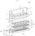
- Fig. 6 illustrates an example ice maker.
- the ice maker 200 is mounted on an ice maker bracket (see reference numeral 250 of Fig. 7 ) disposed on the barrier 111.
- the ice maker 200 includes an upper tray 210 defining an upper appearance thereof, a lower tray 220 defining a lower appearance thereof, a motor assembly for operating one of the upper tray 210 and the lower tray 220, and an ejecting unit for separating ice made on the upper or lower tray 210 or 220.
- the lower tray 220 has an approximately square shape when viewed from an upper side. Also, the lower tray 220 has a recess part 225, which is recessed downward, having a hemispherical shape so that a lower portion of an ice having a spherical or globular shape is made.
- the lower tray 220 may be formed of a metal material. As necessary, at least one portion of the lower tray 120 may be formed of an elastically deformable material. In some examples, only a portion of the lower tray 220 may be formed of an elastic material.
- the lower tray 220 may include a tray case 221 defining an outer appearance thereof, a tray body 223 mounted on the tray case 221 to define the recess part 225 providing a space in which an ice is made, and a tray cover 226 fixing and mounting the tray body 223 to the tray case 221.
- the tray case 221 may have a square frame shape. Also, the tray case 221 may further extend upward and downward along a circumference thereof. Also, a seat part 221a punched in a circular shape is disposed within the tray case 221.
- the seat part 221a may have a shape corresponding to that of the recess part 225 of the tray body 223. Also, the seat part 221a has a rounded inner side surface so that the recess part 225 having the hemispherical shape is stably seated thereon.
- the seat part 221a may be provided in plurality to correspond to the position and shape of the recess part 225. Thus, the plurality of seat parts 221a may be successively arranged in a line and connected to each other.
- the upper tray 210 and the motor assembly 240 are coupled to a rear side of the tray case 221. Also, a lower tray connection part 222 is disposed on the rear side of the tray case 221 so that the tray case 221 is rotatably mounted.
- an elastic member mounting part 221b for mounting the elastic member 231 providing an elastic force to maintain a closed state of the lower tray 220 may be further disposed on a side surface of the tray case 221.
- the tray body 223 may be formed of an elastically deformable flexible material.
- the tray body 223 is seated on the tray case 221.
- the tray body 223 includes a plane part 224 having a shape corresponding to that of the tray body 223 and the recess part 225 recessed from the plane part 224.
- the plane part 224 has a plate shape with a predetermined thickness. Also, the plane part 224 may have a shape to correspond to that of a top surface of the tray case 221 so that the plane part 224 is accommodated into the tray case 221. Also, the recess part 225 may have the hemispherical shape to define a lower shell providing a space in which an ice piece is made. Alternatively, the recess part 225 may have a shape corresponding to that of a recess part 225 of the upper tray 210. Thus, when the upper tray 210 and the lower tray 220 are closed, the shell providing a space having a globular or spherical shape may be defined.
- the recess part 225 may pass through the seat part 221a of the tray case 221 to protrude downward.
- the recess part 225 may be pushed by the ejecting unit when the lower tray 220 is rotated. As a result, an ice within the recess part 225 may be separated to the outside.
- a lower protrusion protruding upward is disposed around the recess part 225.
- the lower protrusion may overlap an upper protrusion of the upper tray 210 to prevent water from leaking.
- the tray cover 226 may be disposed above the tray body 223 to fix the tray body 223 to the tray case 221.
- a screw or rivet may be coupled to the tray cover 226. The screw or rivet successively passes through the tray cover 226, the tray body 223, and the tray case 221 to assemble the lower tray 220.
- a punched part 226a having a shape corresponding to that of an opened top surface of the recess part 225 defined in the tray body 223 is defined in the tray cover 225.
- the punched part 226a may have a shape in which a plurality of circular shapes successively that overlap each other.
- the upper tray 210 defines an upper appearance of the ice maker 200.
- the upper tray 210 may include a mounting part 211 for mounting the ice maker 200 and a tray part 212 for making ice.
- the mounting part 211 is configured to mount the ice maker 200 inside the freezing compartment 113.
- the mounting part 212 may extend in a vertical direction perpendicular to that of the tray part 212.
- the mounting part 211 may surface-contact the freezing compartment 113 to maintain a stably mounted state thereof.
- the tray part 212 may have a shape corresponding to that of the lower tray 220.
- the tray part 212 may include a plurality of recess parts 213 each being recessed upward and having a hemispherical shape. The plurality of recess parts 213 are successively arranged in a line.
- the recess part 225 of the lower tray 220 and the recess part 213 of the upper tray 210 are coupled to match each other in shape to define the shell which provides an ice making space having a globular or spherical shape.
- the recess part 213 of the upper tray 210 may have a hemispherical shape corresponding to that of the lower tray 220.
- a shaft coupling part 211a to which the lower tray connection part 222 is shaft-coupled may be further disposed on a rear side of the tray part 212.
- the shaft coupling part 211a extends downward from both sides of a bottom surface of the tray part 212 and is shaft-coupled to the lower tray connection part 222.
- the lower tray 220 is shaft-coupled to the upper tray 210 and is rotatably mounted on the upper tray 220. That is, the lower tray 220 may be rotatably opened or closed by the rotation of the motor assembly 240.
- the upper tray 210 may be formed entirely of a metal material. Thus, the upper tray 210 may be configured to quickly freeze water within the shell. Also, a heater for heating the upper tray 210 to separate ice from the upper tray 210 may be further disposed on the upper tray 210. Also, a water supply tube for supplying water into a water supply part 214 of the upper tray 210 may be disposed above the upper tray 210.
- the recess part 213 of the upper tray 210 may be formed of an elastic material, like the recess part 210 of the lower tray 220, so that ice pieces are easily separated.
- a rotating arm 230 and the elastic member 231 are disposed on a side of the lower tray 220.
- the rotating arm 230 may be provided for the tension of the elastic member 231.
- the rotating arm 230 may be rotatably mounted on the lower tray 220.
- the rotating arm 230 has one end shaft-coupled to the lower tray connection part 222. Thus, even though the lower tray 220 is in a closed state, the rotating arm 230 may be further rotated to allow the elastic member 231 to be tensioned. Also, the elastic member 231 is mounted between the rotating arm 230 and the elastic member mounting part 221b. The elastic member 231 may include a tension spring. Thus, the rotating arm 230 may be further rotated in a counterclockwise direction in the state where the lower tray 220 is closed to allow the elastic member 231 to be tensioned. As a result, the lower tray 220 may be closely attached to the upper tray 210 by the elastic force of the elastic member 231 to prevent water from leaking during ice-making.
- the motor assembly 240 may be disposed on a side of the upper and lower trays 210 and 220 and include a motor. Also, the motor assembly may include a plurality of gears that are combined with each other to adjust the rotation of the lower tray 220.
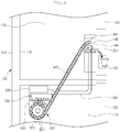
- Fig. 7 illustrates the entire structure of an example ice transfer device.
- Fig. 8 illustrates an example ice transfer state through the ice transfer device shown in FIG. 7 .
- the ice transfer device 300 is disposed in the freezing compartment 113 and connected to the ice bank 140 via the freezing compartment 113, the refrigerating compartment 112, and the first refrigerating compartment door 121 to supply ice made in the ice maker 200 into the ice bank 140.
- the ice transfer device 300 may be mounted within an inner case 115 defining an inner surface of the cabinet 110 and be exposed to the inside of the refrigerator.
- the ice transfer device 300 may be mounted on a member such as a separate bracket coupled to the inner case 115.
- at least one portion of the ice transfer device 300 may be buried in an insulation material that is disposed between an outer case 114 and the inner case 115 of the cabinet 110 to provide insulation properties.
- the ice transfer device 300 includes the housing 310 in which ice pieces transferred from the ice maker 200 are supplied, the transfer member 320 disposed within the housing 310 to transfer the ice within the housing 310, a driving unit 330 for rotating the transfer member 320, and the ice chute 340 for guiding the ice within the housing 310 up to the dispenser 123.
- the housing 310 is disposed under the ice maker 200. Also, the housing 310 provides a space for accommodating ice and the transfer member 320 therein. The housing 310 is opened upward to accommodate ice supplied from the ice maker 200.
- an upper portion of the housing 310 is disposed under the ice maker 200 and exposed to the inside the freezing compartment 113. Also, a lower portion of the housing 310 in which the transfer member 320 is accommodated may be buried in the insulation material between the outer case 114 and the inner case 115.
- the transfer member 320 is disposed within the housing 310.
- the transfer member 320 may have a gear or impeller shape.
- the transfer member 320 may be configured to accommodate the made globular or spherical ice pieces into a space between a plurality of protrusions 321 disposed thereon.
- the entire transfer member 320 may be accommodated in the housing 310.
- a rotation shaft of the transfer member 320 passes though the housing 310 and is exposed to the outside of the housing 310.
- the driving unit 330 is connected to the rotation shaft of the transfer member 320 to provide a power for rotating the transfer member 320.
- the driving unit 330 may be configured to provide a power for rotating the transfer member 320.
- the driving unit 330 includes a driving motor for providing a rotation power and a gear assembly rotated by the driving motor.
- the gear assembly may be provided in plurality. Also, a plurality of gears may be combined with each other to control a rotation rate of the transfer member 320.
- the ice chute 340 guides the ice pieces made in the ice maker 200 into the ice bank 140, and simultaneously, guides cool air circulating between the freezing compartment 113 and the ice bank 140.
- the ice chute 340 extends from a side of the housing 310 up to the first refrigerating compartment door 121 on which the ice bank 140 is mounted.
- the ice chute 340 may have a hollow tube shape so that a globular or spherical ice piece is transferred therethrough.
- the ice chute 340 may have an inner diameter corresponding to that of the globular or spherical ice piece or slightly greater than that of the made globular or spherical ice piece.
- the made ice pieces may be successively transferred in a line.
- the shape of the ice chute 340 is not limited to the cylindrical shape, and thus the ice chute may have various shapes.
- the ice chute 340 may extend to pass through the barrier 111. Also, the ice chute 340 may be mounted so that the chute 340 is exposed to the outside of the freezing compartment 113 and the refrigerating compartment 112. Here, an insulation member may be further provided outside the ice chute 340 to prevent the refrigerating compartment 112 from being heat-exchanged with the ice chute 340.
- the ice chute 340 may be disposed between the outer case 114 and the inner case 115. That is, the ice chute 340 may be disposed within a sidewall of the cabinet 110 corresponding to the first refrigerating compartment door 121. Here, the ice chute 340 may be thermally insulated by an insulation member within the cabinet 110 and not be exposed to the inside of the refrigerator.
- the ice chute 340 may extend up to an inner sidewall of the refrigerating compartment 112 corresponding to a position of the ice bank 140. Also, the opening 341 opened in the inner wall of the refrigerating compartment 112 is defined in an upper end of the ice chute 340.
- the ice bank 140 and the ice chute 340 may communicate with each other.
- ice pieces may move along the ice chute 340 by the rotation of the transfer member 320 and supplied into the ice bank 140.
- the cool air duct 350 together with the ice chute 340 may be configured so that the cool air within the freezing compartment is circulated into the ice bank 140.
- the cool air duct 350 is disposed along the refrigerating compartment 112 at a side of the freezing compartment 113. Also, the cool air duct 350 may be buried within the cabinet 100, like the ice chute 340.
- the cool air duct 350 communicates with the ice bank 140 in the state where the first refrigerating compartment door 121 is closed to supply (or recover) cool air.
- cool air generated in the evaporator may be supplied into the ice maker 200 that is disposed inside the freezing compartment 113.
- a globular or spherical ice piece may be made inside the ice maker 200 using water supplied into the ice maker 200.
- the ice piece drops down by the heater provided in the ice maker 200 or a component for separating the ice.
- An upwardly opened entrance of the housing 310 may be defined under the ice maker 200, and thus the made globular or spherical ice piece may be supplied into the housing 310.
- the ice supplied through the upper side of the housing may move by the rotation of the transfer member 320.
- a plurality of protrusions 321 are disposed on the transfer member 320.
- a space in which each of the globular or spherical ice pieces is accommodated is defined between the protrusions 321.
- ice pieces introduced into the housing 310 are accommodated into the space between the plurality of protrusions 321 disposed on the transfer member 320 by the rotation of the transfer member 320.
- the ice pieces accommodated in the space defined in the transfer member 320 may be transferred by the rotation of the transfer member 320.
- the ice chute 340 may be maintained in a state where the made ice pieces fill the ice chute 340.
- the transfer member 320 may be rotated to push the ice pieces within the ice chute 340, thereby discharging the ice pieces into the ice bank 140.
- the ice pieces discharged into the ice bank 140 are stored in the ice bank 140.
- the ice pieces stored in the ice bank 140 may be dispensed through the dispenser 123 when the dispenser 123 is manipulated.
- a full ice detection device 146 may be provided in the ice bank 140. Further, a full ice detection device 312 may be additionally provided inside the housing 310. A preset amount or more of ice may be filled into the ice bank 140 and the housing 310 by the full ice detection device disposed in each of the ice bank 140 and the housing 310. Also, the operation of the ice maker 200 may be controlled by the full ice detection devices 146 and 312 until the preset amount or more of ice pieces fill the ice bank 140 and the housing 310. In this state, the transfer member 320 may be operated to supply the ice pieces into the ice bank 140.
- the operation of the driving unit 330 may start.
- the transfer member 320 When the transfer member 320 is rotated, the ice pieces accommodated in the space defined in the transfer member 320 may be rotated together to push the ice pieces accommodated in a lower end of the ice chute 340 upward.
- the ice pieces accommodated in the lower end of the ice chute 340 are pushed upward, the ice pieces successively stacked within the ice chute 340 may be pushed at the same time to ascend upward.
- globular or spherical ice pieces may be supplied into the ice bank 140 through the opening 341 of the ice chute 340. Then, the ice pieces may be dispensed to the outside through the dispenser 123.
- each of the ice pieces dispensed through the dispenser 123 may have a globular or spherical shape, and also, the user may dispense the desired number of ice pieces by manipulating the dispenser 123.
- the operation of the driving unit 330 may be restricted by a door sensor for detecting an opening/closing of the refrigerating compartment door 120. That is, when the user manipulates the dispenser 123 in a state where the refrigerating compartment door 120 is opened, the driving unit 330 may not be operated to prevent ice from being dispensed.
- the stopper 400 When the first refrigerating compartment door 121 is opened, the ice pieces moving between the opening 341 of the ice chute and the ice inlet hole 145 may interfere with the stopper 400 to prevent the ice pieces from dropping down on the floor.
- the stopper 400 will be described in more detail.
- Fig. 9 illustrates an example stopper
- Fig. 10 illustrates an example operation of the example stopper.
- Fig. 9 illustrates the stopper 400 in a state where the refrigerating compartment door is opened
- Fig. 10 illustrates an operation of the stopper 400 in a state where the refrigerating compartment door is closed.
- the stopper 400 is disposed on a side of the opening 341 to interfere with the movement of the ice pieces from the ice chute 340 into the ice bank 140.
- the stopper 400 may include a front part 410 and a circumferential part 420 surrounding the front part 410.
- the front part 410 may include a flap 411 extending from the outside of the front part 410 toward a center of the front part 410 and a cool air hole 412 defined in a central portion of the front part 410.
- the flap 411 may be a portion to which a force in a direction opposite to the moving direction of the ice is applied.
- the flap 411 may be provided in plurality.
- the plurality of flaps 411 may be radially disposed along an outer circumference of the front part 410.
- the stopper 400 may be formed of a flexible material so that the stopper is bent to apply resistance to the ice pieces when the ice pieces are discharged and restored in its original position after the ice pieces pass therethrough.
- the stopper 400 may be formed of a silicon material having superior heat resistance, cold resistance, water resistance, and electrical insulation.
- the front part 410, the circumferential part 420, and the flap 411 of the stopper 400 may be integrated with each other.
- the flap 411 may be simply manufactured by cutting a portion of the front part 410 by a predetermined length. In this case, since it is unnecessary to separately manufacture the front part 410, the circumferential part 420, and the flap 411, it may have advantages in manufacturing processes and costs.
- the refrigerator 100 may further include a support member 500 connecting the discharge end 341 of the ice chute 340 to the stopper 400.
- the support member 500 may include an outer wall 510 protruding and extending toward a front surface of the inner case 115 and a first coupling part 520 disposed on an outer circumferential surface of the outer wall 510.
- the stopper 400 may be coupled to the first coupling part 520.
- the stopper 400 may include a second coupling part disposed along the circumferential part 420.
- first and second coupling parts may protrude, and the other one may be inserted.
- the stopper 400 and the support member 500 may be detachably provided by the first and second coupling parts.
- the stopper 400 may be washed or replaced after being separated.
- the stopper 400 and the support member 500 may be integrated with each other.
- the stopper 400 may be directly fixed or detachably coupled to the discharge end 341 of the ice chute.
- the stopper 400 may be coupled to an outer circumferential surface, an inner circumferential surface, or an end of the discharge end 341.
- the stopper 400 may be fixedly or detachably coupled to a sidewall of the refrigerating compartment 112 corresponding to the discharge end 341 of the ice chute.
- a first ice I1 disposed at the uppermost portion of the ice chute 400 and a second ice 12 just after being discharged from the opening 341 of the ice chute 400 are illustrated in Fig. 10 .
- An ice moving from a state of the first ice I1 to a state of the second ice 12 may not be seated on the ice bank 140 to drop onto the floor when the refrigerating compartment door 120 is opened.
- the stopper 400 prevents ice pieces from dropping onto the floor.
- the flap 411 may be maintained in a certain state.
- the flap 411 may be maintained in a state in which the flap 411 is disposed on the same plane as that of the front part 410.
- the ice may cause deformation of the flap 411.
- the flap 411 is bent in a right direction. That is to say, the flap 411 is bent toward the inside of the ice bank 140.
- the flap 411 is formed of a flexible material, the flap 411 is bent to apply resistance to the ice when the ice is discharged via the stopper and then restored in its original position after the ice passes therethrough.
- the flap 411 may bend further so that the ice passes through the flap 411.
- the ice may exit the stopper 400.
- the ice exiting the stopper 410 is in a state in which the ice enters into an inner space of the ice bank 140, the ice may be stably stated in the ice bank 140.
- an operation of the stopper 400 will be described.
- an operation of the driving unit 330 for transferring ice is stopped.
- An ice exiting the state of the second ice 12 is seated in the ice bank 140.
- an ice before exiting the state of the second ice 12 for example, the ice pieces in the states of the first and second ices I1 and I2 may be stably fixed between the stopper 400 and the ice chute 340 by a force applied to the ice pieces from the flap 411, as described above.
- an ice in the state of the second ice 12 may drop down on the floor. Also, an ice in the state of the first ice I1 may exit the ice chute 340 to drop down on the floor when a slight external force is applied to the refrigerator 100 or an internal vibration occurs in the refrigerator 100. Thus, the ice pieces from the state of the first ice I1 to the state of the second ice 12 may not drop down out of the refrigerator and may be stably transferred into the ice bank 140.
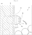
- Fig. 11 illustrates another example stopper 400.
- a stopper 400 is disposed above an opening 341.
- the stopper 400 includes a damper 414 for interfering with movement of an ice piece and a rotation shaft 415 for rotatably coupling the damper 414 with respect to the opening 341.
- the damper 414 may have a shape substantially corresponding to that of the opening 341.
- the damper 414 may have a size to cover only a portion of the opening 341. This is done so that cool air flowing through an ice chute 340 may be smoothly circulated.
- the damper 414 has a semicircular shape in Fig. 11 , the present disclosure is not limited thereto. Also, the damper 414 may be provided in plurality.
- the rotation shaft 415 may be a portion at which the damper 414 is coupled to an inner case 115.
- the rotation shaft 415 is disposed above the damper 414.
- the damper 414 may be vertically rotated with respect to the rotation shaft 415.
- the damper 414 applies a force to an ice in a direction opposite to the moving direction of the ice. However, the damper 414 returns to a position for covering the opening 341 by the self-weight of the damper 414.
- the damper 414 is rotated in a counterclockwise direction.
- a force for returning in a clockwise direction by the self-weight is applied to the damper 414.
- the damper 414 applies a force in a direction opposite to the moving direction of the ice with respect to the ice.
- a material for forming the damper 414 is not limited to a flexible material.
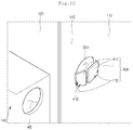
- Fig. 12 illustrates yet another example stopper 400.
- a stopper 400 is disposed on a side of an opening 341.
- the stopper 400 may be disposed at a lower side of the opening 341 as shown in Fig. 12 .
- the stopper 400 may include a damper 414 for interfering with movement of an ice piece, a rotation shaft 415 provided on a side of the damper 414, and a spring 416 provided on a side of the rotation shaft 415.
- the spring 416 may be a member that provides an elastic force so that the damper 414 is maintained at a position for covering the opening 341.
- the spring 416 may be provided as a torsion spring.
- the damper 414 applies a force to an ice in a direction opposite to the moving direction of the ice. However, the damper 414 returns to a position for covering the opening 341 by the elastic force of the spring 416.
- the damper 414 is rotated in a clockwise direction.
- a force for returning in a counterclockwise direction by the elastic force of the spring 416 is applied to the damper 414.
- the damper 414 applies a force in a direction opposite to the moving direction of the ice with respect to the ice.
- a material for forming the damper 414 is not limited to a flexible material.
- the ice maker is disposed in the freezing compartment to omit a separate space for providing the ice maker.
- a space for storing may be expanded in the back surface of the refrigerating compartment door.
- the storage capacity of the refrigerator may be expanded while maintaining the convenience of use.
- the stopper may prevent the ice from dropping down.
- waste of ice may be prevented, and the convenience of use may be improved.
- the stopper since the stopper uses a simple mechanical structure without using the control of an additional sensor or motor, it may have an advantage in cost. Also, when the ice maker is broken down, the ice maker may be easily replaced and repaired.
Description
- The present disclosure relates to a refrigerator.
- In general, refrigerators are home appliances for storing foods at a low temperature in an inner storage space covered by a door. That is, since such a refrigerator cools the inside of a storage space by using cool air generated through heat-exchange with a refrigerant circulating a refrigeration cycle, foods stored in the storage space may be stored in an state that slows spoilage.
- Also, an ice maker for making ice may be provided inside the refrigerator. The ice maker is configured so that water supplied from a water supply source or a water tank is accommodated into an ice tray to make ice pieces. Also, a dispenser for dispensing purified water or ice made in the ice maker to the outside may be provided in the refrigerating compartment door.
-
US 2012/0023999 A1 relates to a refrigerator having an ice transfer unit, wherein the refrigerator includes: a refrigerator main body including a freezing chamber positioned at a lower portion thereof and a refrigerating chamber positioned at an upper portion thereof; an ice maker and an ice bank positioned at an inner side of the freezing chamber; an ice dispenser positioned at an inner side of the refrigerating chamber; a transfer flow path extending from the ice bank to the ice dispenser; an ice input unit supplying ice stored in the ice bank to the interior of the transfer flow path; and a blower blowing air to allow the ice supplied to the interior of the ice transfer flow path toward the ice dispenser. -
KR 200 154 593 Y1 -
EP 1 598 618 A1 - The objects are solved by the features of the independent claim. A refrigerator includes a cabinet defining a refrigerating compartment and a freezing compartment, a refrigerating compartment door configured to open and close at least a portion of the refrigerating compartment, and an ice bank mounted on the refrigerating compartment door and configured to store ice therein. The refrigerator also includes a dispenser disposed under the ice bank and configured to dispense ice stored in the ice bank and an ice maker provided in the freezing compartment and configured to make ice. The refrigerator further includes a transfer member connected to the ice maker and configured to transfer ice made in the ice maker to the ice bank and an ice chute connecting an outlet of the transfer member to the ice bank. The ice chute defines an ice transfer passage between the transfer member and the ice bank. In addition, the refrigerator includes a stopper disposed on a discharge end of the ice chute and configured to block discharge of ice from the ice chute in a state in which the refrigerating compartment door is opened.
- Implementations may include one or more of the following features. For example, the stopper may have a shape that covers the discharge end of the ice chute and may have a plurality of flaps defined by a plurality of cutoff lines that are arranged radially from a center of the stopper. In this example, the stopper may apply resistance to ice passing through the stopper and may bend to enable ice pushed with a sufficient amount of force to discharge. The stopper may be made of a flexible material that restores to its original position after ice passes therethrough. The stopper may be made of a silicon material. A cool air hole may be defined in a center of the stopper. The cool air hole may have a diameter that is less than a diameter of an ice piece that passes through the stopper.
- According to the present invention, the stopper includes a damper configured to rotate to open and close at least a portion of the discharge end of the ice chute and the damper applies resistance to ice passing through the stopper, rotates to enable ice pushed with a sufficient amount of force to discharge through the stopper, and returns to its original position by a self-weight or a flexible material thereof or by a restoring force of a spring after the ice passes therethrough. In these implementations, a rotation shaft of the damper may be disposed above the discharge end of the ice chute.
- In some examples, a spring may be coupled to a rotation shaft of the damper. According to the present invention, the damper applies resistance to ice passing through the stopper, rotates to enable ice pushed with a sufficient amount of force to discharge through the stopper, and returns to its original position by a restoring force of the spring after the ice passes therethrough.
- In addition, the refrigerator may include a support member connecting the discharge end of the ice chute to the stopper and the stopper may be coupled to the support member. The stopper may be coupled to the discharge end of the ice chute. The stopper may be coupled to a sidewall of the refrigerating compartment corresponding to the discharge end of the ice chute.
- In some implementations, the ice maker may be configured to make spherical ice pieces. In these implementations, the ice maker may include an upper tray comprising a first recess part recessed in a hemispherical shape and a lower tray comprising a second recess part recessed in a hemispherical shape. The upper tray and the lower tray may be arranged such that the first recess part is recessed away from the lower tray and the second recess part is recessed away from the upper tray.
- In another aspect, a refrigerator includes a cabinet defining a freezing compartment therein, the cabinet having an open side. The refrigerator also includes a door configured to open and close to expose and cover at least a portion of the open side of the cabinet and an ice bank disposed on a back surface of the door and configured to store ice. The refrigerator further includes an ice maker disposed within the cabinet and configured to make ice, a transfer member connected to the ice maker and configured to transfer ice made in the ice maker to the ice bank, and an ice chute connecting an outlet of the transfer member to the ice bank. The ice chute defines an ice transfer passage between the transfer member and the ice bank. In addition, the refrigerator includes a stopper disposed on a discharge end of the ice chute and configured to interfere with discharge of ice from the ice chute.
- Implementations may include one or more of the following features. For example, the stopper may include a front part disposed on the discharge end of the ice chute and a plurality of flaps defined by radial cuts made to the front part of the stopper. In this example, the plurality of flaps may bend toward an inside of the ice bank based on the transfer member transferring an ice piece to the ice bank through the stopper.
- The stopper may be detachably coupled to the discharge end of the ice chute. At least a portion of the stopper may be disposed within the ice bank in a state in which the door covers the open side of the cabinet.
- In some implementations, the ice maker may be configured to make spherical ice pieces. In these implementations, the ice maker may include an upper tray comprising a first recess part recessed in a hemispherical shape and a lower tray comprising a second recess part recessed in a hemispherical shape. The upper tray and the lower tray may be arranged such that the first recess part is recessed away from the lower tray and the second recess part is recessed away from the upper tray.
- The details of one or more implementations are set forth in the accompanying drawings and the description below. Other features will be apparent from the description and drawings, and from the claims.
-
-
Fig. 1 is a perspective view of an example refrigerator. -
Fig. 2 is a perspective view illustrating an example cool air circulation state within the inside of the refrigerator shown inFIG. 1 and an ice making compartment in the refrigerator shown inFIG. 1 . -
Fig. 3 is a perspective view of an example refrigerator with a door opened. -
Fig. 4 is a perspective of an example ice bank with a door opened. -
Fig. 5 is a partially perspective view illustrating the inside of an example freezing compartment. -
Fig. 6 is an exploded perspective view of an example ice maker. -
Fig. 7 is a perspective view illustrating the entire structure of an example ice transfer device. -
Fig. 8 is a schematic view illustrating an example ice transfer state through the example ice transfer device. -
Fig. 9 is a perspective view of an example stopper. -
Fig. 10 is a view illustrating an operation of the example stopper. -
Fig. 11 is a perspective view of another example stopper. -
Fig. 12 is a perspective view of yet another example stopper. - Reference will now be made in detail to the embodiments of the present disclosure, examples of which are illustrated in the accompanying drawings.
- In the following detailed description of the preferred embodiments, reference is made to the accompanying drawings that form a part hereof, and in which is shown by way of illustration specific preferred embodiments in which the invention may be practiced. These embodiments are described in sufficient detail to enable those skilled in the art to practice the invention, and it is understood that other embodiments may be utilized and that logical structural, mechanical, electrical, and chemical changes may be made without departing from the scope of the invention. To avoid detail not necessary to enable those skilled in the art to practice the invention, the description may omit certain information known to those skilled in the art. The following detailed description is, therefore, not to be taken in a limiting sense.
-
Fig. 1 illustrates an example refrigerator.Fig. 2 is illustrates an example cool air circulation state within the inside of the refrigerator shown inFIG. 1 and an example ice making compartment in the refrigerator shown inFIG. 1 . - Referring to
Figs. 1 and2 , arefrigerator 1 includes acabinet 10 defining a storage space anddoors cabinet 10. An outer appearance of therefrigerator 1 may be defined by thecabinet 10 and thedoors - The storage space within the
cabinet 10 is vertically partitioned by abarrier 11. A refrigeratingcompartment 12 is defined in the partitioned upper side, and a freezingcompartment 13 is defined in the partitioned lower side. - The
doors refrigerating compartment door 20 for opening or closing therefrigerating compartment 12 and a freezingcompartment door 30 for opening or closing the freezingcompartment 13. - The refrigerating
compartment door 20 includes a plurality of doors disposed on left and right sides thereof. The plurality of doors include a firstrefrigerating compartment door 21, and a second refrigerating compartment door 22 disposed at a right side of the firstrefrigerating compartment door 21. The firstrefrigerating compartment door 21 and the second refrigerating compartment door 22 are independently rotated with respect to each other. - The freezing
compartment door 30 may be provided as a slidably accessible door. The freezingcompartment door 30 includes a plurality of doors that are vertically disposed. The freezingcompartment door 30 may be provided as one door as needed. - A
dispenser 23 for dispensing water or ice is disposed in one of the firstrefrigerating compartment door 21 and the second refrigerating compartment door 22. For example, a structure in which thedispenser 23 is disposed in the firstrefrigerating compartment door 21 is illustrated inFig. 1 . - An
ice making compartment 40 for making and storing ice is defined in the firstrefrigerating compartment door 21. Theice making compartment 40 is provided as an independent insulation space. Theice making compartment 40 may be opened or closed by an icemaking compartment door 41. An ice maker for making ice may be provided within theice making compartment 40. Also, components for storing made ice or dispensing the made ice through thedispenser 23 may be provided in theice making compartment 40. - A
cool air inlet 42 and acool air outlet 43 which communicate with acool air duct 50 disposed in thecabinet 10 when the firstrefrigerating compartment door 21 is closed are provided in one surface of theice making compartment 40. Cool air introduced into thecool air inlet 42 cools the inside of theice making compartment 40 to make ice. Then, the heat-exchanged cool air is discharged to the outside of theice making compartment 40 through thecool air outlet 43. - A
heat exchange chamber 14 partitioned from the freezingcompartment 13 is defined in a rear side of the freezingcompartment 13. An evaporator is provided in theheat exchange chamber 14. Cool air generated in the evaporator may be supplied into the freezingcompartment 13, the refrigeratingcompartment 12, and theice making compartment 40 to cool the inside of each of the freezingcompartment 13, the refrigeratingcompartment 12, and theice making compartment 40. - Also, the
cool air duct 50 for supplying cool air into theice making compartment 40 and recovering the cool air from theice making compartment 40 is disposed in a side wall of thecabinet 10. Thecool air duct 50 extends from a side of the freezingcompartment 13 to an upper portion of therefrigerating compartment 12. When the firstrefrigerating compartment door 21 is closed, thecool air duct 50 communicates with thecool air inlet 42 and thecool air outlet 43. Also, thecool air duct 50 communicates with theheat exchange chamber 14 and the freezingcompartment 13. - Thus, cool air within the
heat exchange chamber 14 is introduced into theice making compartment 40 through asupply passage 51 of thecool air duct 50. Also, cool air within theice making compartment 40 is recovered into the freezingcompartment 13 through arecovery passage 52 of thecool air duct 50. Ice is made and stored within theice making compartment 40 by continuous circulation of the cool air through thecool air duct 50. - In the refrigerator having the above-described structure, making and storage of ice is performed within the
ice making compartment 40 provided in therefrigerating compartment 20, which increases a volume of the refrigeratingcompartment door 20. Thus, an accommodation space defined in a back surface of the refrigeratingcompartment door 20 may be reduced. - Also, since cool air for making ice is supplied up to the ice making compartment, power consumption may be increased.
-
Fig. 3 illustrates an example refrigerator with a door opened,Fig. 4 illustrates an example ice bank with a door opened, andFig. 5 illustrates the inside of an example freezing compartment. - Referring to
Figs. 3 to 5 , arefrigerator 100 includes acabinet 110 and a door. Here, thecabinet 110 and the door define an outer appearance of therefrigerator 100. The inside of thecabinet 110 is partitioned by abarrier 111. That is, arefrigerating compartment 112 is defined at an upper side, and a freezingcompartment 113 is defined at a lower side. - An
ice maker 200 for making ice and anice transfer device 300 for transferring the made ice into anice bank 140 may be provided within the freezingcompartment 113. Also, anice chute 340 and acool air duct 350 of theice transfer device 300 haveopenings refrigerating compartment 112. Theopening 341 of theice chute 340 may be called a "discharge end 341" because ice is discharged into theice bank 140 from theice chute 340 through theopening 341 of theice chute 340. - The door includes a
refrigerating compartment door 120 for covering therefrigerating compartment 112 and a freezingcompartment door 130 for covering the freezingcompartment 113. The refrigeratingcompartment door 120 includes a firstrefrigerating compartment door 121 and a secondrefrigerating compartment door 122 which are rotated to open or close therefrigerating compartment 112. Also, the freezingcompartment door 130 may be slidably withdrawn in front and rear directions to open or close the freezingcompartment 113. - A
dispenser 123 may be provided in a front surface of the firstrefrigerating compartment door 121. Purified water and ice made in theice maker 200 may be dispensed to the outside through thedispenser 123. - The
ice bank 140 is provided in a back surface of the refrigeratingcompartment door 120. Theice bank 140 provides a space for storing ice transferred by theice transfer device 300. Also, theice bank 140 may be openable by the firstrefrigerating compartment door 121. Theice bank 140 defines an insulation space. Also, when the firstrefrigerating compartment door 121 is closed, theice bank 140 is connected to theice chute 340 and thecool air duct 350 to allow ice to be supplied and cool air to be circulated. Theice bank 140 communicates with thedispenser 123. Thus, when thedispenser 123 is manipulated, ice stored in theice bank 140 may be dispensed. Also, aseparate case 142 for accommodating ice may be provided within theice bank 140. Further, anauger 143 configured to smoothly transfer ice and a blade for crushing ice to dispense ice pieces may be further provided within theice bank 140. - Also, the
ice bank 140 protrudes to contact an inner sidewall of therefrigerating compartment 112 when the firstrefrigerating compartment door 121 is closed. Anair hole 144 and anice inlet hole 145 may be further defined in a sidewall of theice bank 140 corresponding to theopenings ice chute 340 and thecool air duct 350 which are disposed in the inner sidewall of therefrigerating compartment 112. Thus, when the firstrefrigerating compartment door 121 is closed, the made ice and the cool air for maintaining the ice may be supplied into theice bank 140. - A stopper (see
reference numeral 400 ofFig. 9 ) is disposed on a side of theopening 341 of theice chute 340. Thestopper 400 may be a member for interfering with the ice transferred from theopening 341 of theice chute 340 into theice inlet hole 145. The ice transferred between the opening 341 of theice chute 340 and theice inlet hole 145 may stay between thestopper 400 and theice chute 340 by the interference of thestopper 400. Thus, according to the present invention, thestopper 400 prevents the ice from dropping down on the floor when the firstrefrigerating compartment door 121 is opened. - A withdrawable drawer, the
ice maker 200, and theice transfer device 300 may be disposed inside the freezingcompartment 113. - The
ice maker 200 is configured to make ice by using water supplied from the water supply source. Theice maker 200 may be disposed in a left upper side of the freezingcompartment 113. Theice maker 200 is fixedly mounted on a bottom surface of thebarrier 111. The ice made in theice maker 200 may drop down and fall into ahousing 310 of theice transfer device 300. - Also, the
ice transfer device 300 for supplying the ice made in theice maker 200 into theice bank 140 may be disposed under theice maker 200. That is, the positions of theice maker 200 and theice transfer device 300 may be determined by the position of theice bank 140. Here, theice maker 200 and theice transfer device 300 may be disposed in a left upper side of the freezingcompartment 113 so that each of theice maker 200 and theice transfer device 300 and theice bank 140 disposed in the firstrefrigerating compartment door 121 have the shortest distance therebetween. - The
ice transfer device 300 may be disposed under theice maker 200 and fixedly mounted on a sidewall of the freezingcompartment 113. Atransfer member 320 for transferring ice may be disposed within thehousing 310. Thehousing 310 may be connected to theice chute 340 to transfer the made ice into theice bank 140 through theice chute 340. Also, the cool air around the ice transferred along theice chute 340 may be recovered into (or supplied from) the freezingcompartment 113. - The
cool air duct 350 is disposed on a side of theice transfer device 300. Thecool air duct 350 is configured to supply (or recover) the cool air of the freezingcompartment 113 into theice bank 140. An entrance of the cool air duct may be exposed to the inside of the freezingcompartment 113, and a blower fan 353 (seeFig. 7 ) may be disposed on a side of thecool air duct 350. - When the
blower fan 353 is rotated forwardly, the cool air of the freezingcompartment 113 may be supplied into theice bank 140 through thecool air duct 350, and the cool air supplied into theice bank 140 may be recovered into the freezingcompartment 113 through theice chute 340. On the other hand, when theblower fan 353 is rotated reversely, the cool air of the freezingcompartment 113 may be supplied into theice bank 140 through theice chute 340, and the cool air supplied into theice bank 140 may be recovered into the freezingcompartment 113 through thecool air duct 350. That is to say, one of theice chute 340 and thecool air duct 350 may serve as a "cool air supply duct" for supplying cool air into theice bank 140, and the other one of theice chute 340 and thecool air duct 350 may serve as a "cool air recovery duct" for recovering cool air of theice bank 140 into the freezingcompartment 113. -
Fig. 6 illustrates an example ice maker. Referring toFig. 6 , theice maker 200 is mounted on an ice maker bracket (seereference numeral 250 ofFig. 7 ) disposed on thebarrier 111. Also, theice maker 200 includes anupper tray 210 defining an upper appearance thereof, alower tray 220 defining a lower appearance thereof, a motor assembly for operating one of theupper tray 210 and thelower tray 220, and an ejecting unit for separating ice made on the upper orlower tray - For instance, the
lower tray 220 has an approximately square shape when viewed from an upper side. Also, thelower tray 220 has arecess part 225, which is recessed downward, having a hemispherical shape so that a lower portion of an ice having a spherical or globular shape is made. Thelower tray 220 may be formed of a metal material. As necessary, at least one portion of thelower tray 120 may be formed of an elastically deformable material. In some examples, only a portion of thelower tray 220 may be formed of an elastic material. - The
lower tray 220 may include atray case 221 defining an outer appearance thereof, atray body 223 mounted on thetray case 221 to define therecess part 225 providing a space in which an ice is made, and atray cover 226 fixing and mounting thetray body 223 to thetray case 221. - The
tray case 221 may have a square frame shape. Also, thetray case 221 may further extend upward and downward along a circumference thereof. Also, aseat part 221a punched in a circular shape is disposed within thetray case 221. Theseat part 221a may have a shape corresponding to that of therecess part 225 of thetray body 223. Also, theseat part 221a has a rounded inner side surface so that therecess part 225 having the hemispherical shape is stably seated thereon. Theseat part 221a may be provided in plurality to correspond to the position and shape of therecess part 225. Thus, the plurality ofseat parts 221a may be successively arranged in a line and connected to each other. - Also, the
upper tray 210 and themotor assembly 240 are coupled to a rear side of thetray case 221. Also, a lowertray connection part 222 is disposed on the rear side of thetray case 221 so that thetray case 221 is rotatably mounted. - Also, an elastic
member mounting part 221b for mounting theelastic member 231 providing an elastic force to maintain a closed state of thelower tray 220 may be further disposed on a side surface of thetray case 221. - The
tray body 223 may be formed of an elastically deformable flexible material. Thetray body 223 is seated on thetray case 221. Thetray body 223 includes aplane part 224 having a shape corresponding to that of thetray body 223 and therecess part 225 recessed from theplane part 224. - The
plane part 224 has a plate shape with a predetermined thickness. Also, theplane part 224 may have a shape to correspond to that of a top surface of thetray case 221 so that theplane part 224 is accommodated into thetray case 221. Also, therecess part 225 may have the hemispherical shape to define a lower shell providing a space in which an ice piece is made. Alternatively, therecess part 225 may have a shape corresponding to that of arecess part 225 of theupper tray 210. Thus, when theupper tray 210 and thelower tray 220 are closed, the shell providing a space having a globular or spherical shape may be defined. - The
recess part 225 may pass through theseat part 221a of thetray case 221 to protrude downward. Thus, therecess part 225 may be pushed by the ejecting unit when thelower tray 220 is rotated. As a result, an ice within therecess part 225 may be separated to the outside. - Also, a lower protrusion protruding upward is disposed around the
recess part 225. When theupper tray 210 and thelower tray 220 are closed with respect to each other, the lower protrusion may overlap an upper protrusion of theupper tray 210 to prevent water from leaking. - The
tray cover 226 may be disposed above thetray body 223 to fix thetray body 223 to thetray case 221. A screw or rivet may be coupled to thetray cover 226. The screw or rivet successively passes through thetray cover 226, thetray body 223, and thetray case 221 to assemble thelower tray 220. - A punched
part 226a having a shape corresponding to that of an opened top surface of therecess part 225 defined in thetray body 223 is defined in thetray cover 225. The punchedpart 226a may have a shape in which a plurality of circular shapes successively that overlap each other. Thus, when thelower tray 220 is completely assembled, therecess part 225 is exposed through the punchedpart 226a, and the lower protrusion is disposed inside the punchedpart 226a. - The
upper tray 210 defines an upper appearance of theice maker 200. Theupper tray 210 may include a mountingpart 211 for mounting theice maker 200 and atray part 212 for making ice. - In detail, the mounting
part 211 is configured to mount theice maker 200 inside the freezingcompartment 113. The mountingpart 212 may extend in a vertical direction perpendicular to that of thetray part 212. Thus, the mountingpart 211 may surface-contact the freezingcompartment 113 to maintain a stably mounted state thereof. - Also, the
tray part 212 may have a shape corresponding to that of thelower tray 220. Thetray part 212 may include a plurality ofrecess parts 213 each being recessed upward and having a hemispherical shape. The plurality ofrecess parts 213 are successively arranged in a line. When theupper tray 210 and thelower tray 220 are closed, therecess part 225 of thelower tray 220 and therecess part 213 of theupper tray 210 are coupled to match each other in shape to define the shell which provides an ice making space having a globular or spherical shape. Therecess part 213 of theupper tray 210 may have a hemispherical shape corresponding to that of thelower tray 220. - A
shaft coupling part 211a to which the lowertray connection part 222 is shaft-coupled may be further disposed on a rear side of thetray part 212. Theshaft coupling part 211a extends downward from both sides of a bottom surface of thetray part 212 and is shaft-coupled to the lowertray connection part 222. Thus, thelower tray 220 is shaft-coupled to theupper tray 210 and is rotatably mounted on theupper tray 220. That is, thelower tray 220 may be rotatably opened or closed by the rotation of themotor assembly 240. - The
upper tray 210 may be formed entirely of a metal material. Thus, theupper tray 210 may be configured to quickly freeze water within the shell. Also, a heater for heating theupper tray 210 to separate ice from theupper tray 210 may be further disposed on theupper tray 210. Also, a water supply tube for supplying water into awater supply part 214 of theupper tray 210 may be disposed above theupper tray 210. - The
recess part 213 of theupper tray 210 may be formed of an elastic material, like therecess part 210 of thelower tray 220, so that ice pieces are easily separated. - A
rotating arm 230 and theelastic member 231 are disposed on a side of thelower tray 220. Therotating arm 230 may be provided for the tension of theelastic member 231. Therotating arm 230 may be rotatably mounted on thelower tray 220. - The
rotating arm 230 has one end shaft-coupled to the lowertray connection part 222. Thus, even though thelower tray 220 is in a closed state, therotating arm 230 may be further rotated to allow theelastic member 231 to be tensioned. Also, theelastic member 231 is mounted between therotating arm 230 and the elasticmember mounting part 221b. Theelastic member 231 may include a tension spring. Thus, therotating arm 230 may be further rotated in a counterclockwise direction in the state where thelower tray 220 is closed to allow theelastic member 231 to be tensioned. As a result, thelower tray 220 may be closely attached to theupper tray 210 by the elastic force of theelastic member 231 to prevent water from leaking during ice-making. - The
motor assembly 240 may be disposed on a side of the upper andlower trays lower tray 220. -
Fig. 7 illustrates the entire structure of an example ice transfer device.Fig. 8 illustrates an example ice transfer state through the ice transfer device shown inFIG. 7 . - Referring to
Figs. 7 and8 , theice transfer device 300 is disposed in the freezingcompartment 113 and connected to theice bank 140 via the freezingcompartment 113, therefrigerating compartment 112, and the firstrefrigerating compartment door 121 to supply ice made in theice maker 200 into theice bank 140. - The
ice transfer device 300 may be mounted within aninner case 115 defining an inner surface of thecabinet 110 and be exposed to the inside of the refrigerator. Here, theice transfer device 300 may be mounted on a member such as a separate bracket coupled to theinner case 115. Also, at least one portion of theice transfer device 300 may be buried in an insulation material that is disposed between anouter case 114 and theinner case 115 of thecabinet 110 to provide insulation properties. - The
ice transfer device 300 includes thehousing 310 in which ice pieces transferred from theice maker 200 are supplied, thetransfer member 320 disposed within thehousing 310 to transfer the ice within thehousing 310, adriving unit 330 for rotating thetransfer member 320, and theice chute 340 for guiding the ice within thehousing 310 up to thedispenser 123. - The
housing 310 is disposed under theice maker 200. Also, thehousing 310 provides a space for accommodating ice and thetransfer member 320 therein. Thehousing 310 is opened upward to accommodate ice supplied from theice maker 200. - Here, an upper portion of the
housing 310 is disposed under theice maker 200 and exposed to the inside the freezingcompartment 113. Also, a lower portion of thehousing 310 in which thetransfer member 320 is accommodated may be buried in the insulation material between theouter case 114 and theinner case 115. - Also, the
transfer member 320 is disposed within thehousing 310. Thetransfer member 320 may have a gear or impeller shape. Thetransfer member 320 may be configured to accommodate the made globular or spherical ice pieces into a space between a plurality ofprotrusions 321 disposed thereon. - Here, the
entire transfer member 320 may be accommodated in thehousing 310. A rotation shaft of thetransfer member 320 passes though thehousing 310 and is exposed to the outside of thehousing 310. Also, the drivingunit 330 is connected to the rotation shaft of thetransfer member 320 to provide a power for rotating thetransfer member 320. - The driving
unit 330 may be configured to provide a power for rotating thetransfer member 320. The drivingunit 330 includes a driving motor for providing a rotation power and a gear assembly rotated by the driving motor. The gear assembly may be provided in plurality. Also, a plurality of gears may be combined with each other to control a rotation rate of thetransfer member 320. - The
ice chute 340 guides the ice pieces made in theice maker 200 into theice bank 140, and simultaneously, guides cool air circulating between the freezingcompartment 113 and theice bank 140. Theice chute 340 extends from a side of thehousing 310 up to the firstrefrigerating compartment door 121 on which theice bank 140 is mounted. Thus, theice chute 340 may have a hollow tube shape so that a globular or spherical ice piece is transferred therethrough. When theice chute 340 has a cylindrical shape, theice chute 340 may have an inner diameter corresponding to that of the globular or spherical ice piece or slightly greater than that of the made globular or spherical ice piece. Thus, the made ice pieces may be successively transferred in a line. However, the shape of theice chute 340 is not limited to the cylindrical shape, and thus the ice chute may have various shapes. - The
ice chute 340 may extend to pass through thebarrier 111. Also, theice chute 340 may be mounted so that thechute 340 is exposed to the outside of the freezingcompartment 113 and therefrigerating compartment 112. Here, an insulation member may be further provided outside theice chute 340 to prevent therefrigerating compartment 112 from being heat-exchanged with theice chute 340. - The
ice chute 340 may be disposed between theouter case 114 and theinner case 115. That is, theice chute 340 may be disposed within a sidewall of thecabinet 110 corresponding to the firstrefrigerating compartment door 121. Here, theice chute 340 may be thermally insulated by an insulation member within thecabinet 110 and not be exposed to the inside of the refrigerator. - The
ice chute 340 may extend up to an inner sidewall of therefrigerating compartment 112 corresponding to a position of theice bank 140. Also, theopening 341 opened in the inner wall of therefrigerating compartment 112 is defined in an upper end of theice chute 340. - Thus, when the first
refrigerating compartment door 121 is closed, theice bank 140 and theice chute 340 may communicate with each other. Thus, ice pieces may move along theice chute 340 by the rotation of thetransfer member 320 and supplied into theice bank 140. - The
cool air duct 350 together with theice chute 340 may be configured so that the cool air within the freezing compartment is circulated into theice bank 140. Thecool air duct 350 is disposed along therefrigerating compartment 112 at a side of the freezingcompartment 113. Also, thecool air duct 350 may be buried within thecabinet 100, like theice chute 340. Thecool air duct 350 communicates with theice bank 140 in the state where the firstrefrigerating compartment door 121 is closed to supply (or recover) cool air. - When the
refrigerator 100 is operating, cool air generated in the evaporator may be supplied into theice maker 200 that is disposed inside the freezingcompartment 113. A globular or spherical ice piece may be made inside theice maker 200 using water supplied into theice maker 200. When the ice piece is completely made, the ice piece drops down by the heater provided in theice maker 200 or a component for separating the ice. - An upwardly opened entrance of the
housing 310 may be defined under theice maker 200, and thus the made globular or spherical ice piece may be supplied into thehousing 310. The ice supplied through the upper side of the housing may move by the rotation of thetransfer member 320. - In detail, a plurality of
protrusions 321 are disposed on thetransfer member 320. A space in which each of the globular or spherical ice pieces is accommodated is defined between theprotrusions 321. Thus, ice pieces introduced into thehousing 310 are accommodated into the space between the plurality ofprotrusions 321 disposed on thetransfer member 320 by the rotation of thetransfer member 320. - The ice pieces accommodated in the space defined in the
transfer member 320 may be transferred by the rotation of thetransfer member 320. Thus, theice chute 340 may be maintained in a state where the made ice pieces fill theice chute 340. Here, thetransfer member 320 may be rotated to push the ice pieces within theice chute 340, thereby discharging the ice pieces into theice bank 140. - The ice pieces discharged into the
ice bank 140 are stored in theice bank 140. The ice pieces stored in theice bank 140 may be dispensed through thedispenser 123 when thedispenser 123 is manipulated. - Also, a full
ice detection device 146 may be provided in theice bank 140. Further, a fullice detection device 312 may be additionally provided inside thehousing 310. A preset amount or more of ice may be filled into theice bank 140 and thehousing 310 by the full ice detection device disposed in each of theice bank 140 and thehousing 310. Also, the operation of theice maker 200 may be controlled by the fullice detection devices ice bank 140 and thehousing 310. In this state, thetransfer member 320 may be operated to supply the ice pieces into theice bank 140. - When a user manipulates the
dispenser 123 in the state where theice bank 140 is fully filled with ice, the operation of thedriving unit 330 may start. When thetransfer member 320 is rotated, the ice pieces accommodated in the space defined in thetransfer member 320 may be rotated together to push the ice pieces accommodated in a lower end of theice chute 340 upward. When the ice pieces accommodated in the lower end of theice chute 340 are pushed upward, the ice pieces successively stacked within theice chute 340 may be pushed at the same time to ascend upward. Also, globular or spherical ice pieces may be supplied into theice bank 140 through theopening 341 of theice chute 340. Then, the ice pieces may be dispensed to the outside through thedispenser 123. - Here, each of the ice pieces dispensed through the
dispenser 123 may have a globular or spherical shape, and also, the user may dispense the desired number of ice pieces by manipulating thedispenser 123. - The operation of the
driving unit 330 may be restricted by a door sensor for detecting an opening/closing of the refrigeratingcompartment door 120. That is, when the user manipulates thedispenser 123 in a state where the refrigeratingcompartment door 120 is opened, the drivingunit 330 may not be operated to prevent ice from being dispensed. - When the first
refrigerating compartment door 121 is opened, the ice pieces moving between the opening 341 of the ice chute and theice inlet hole 145 may interfere with thestopper 400 to prevent the ice pieces from dropping down on the floor. Hereinafter, thestopper 400 will be described in more detail. -
Fig. 9 illustrates an example stopper, andFig. 10 illustrates an example operation of the example stopper. In detail,Fig. 9 illustrates thestopper 400 in a state where the refrigerating compartment door is opened, andFig. 10 illustrates an operation of thestopper 400 in a state where the refrigerating compartment door is closed. - The
stopper 400 is disposed on a side of theopening 341 to interfere with the movement of the ice pieces from theice chute 340 into theice bank 140. - In detail, the
stopper 400 may include afront part 410 and acircumferential part 420 surrounding thefront part 410. - The
front part 410 may include aflap 411 extending from the outside of thefront part 410 toward a center of thefront part 410 and a cool air hole 412 defined in a central portion of thefront part 410. - The
flap 411 may be a portion to which a force in a direction opposite to the moving direction of the ice is applied. Theflap 411 may be provided in plurality. The plurality offlaps 411 may be radially disposed along an outer circumference of thefront part 410. Thus, due to the above-described structure, thestopper 400 may stably prevent the ice pieces from being separated. - The
stopper 400 may be formed of a flexible material so that the stopper is bent to apply resistance to the ice pieces when the ice pieces are discharged and restored in its original position after the ice pieces pass therethrough. Particularly, thestopper 400 may be formed of a silicon material having superior heat resistance, cold resistance, water resistance, and electrical insulation. - The
front part 410, thecircumferential part 420, and theflap 411 of thestopper 400 may be integrated with each other. Theflap 411 may be simply manufactured by cutting a portion of thefront part 410 by a predetermined length. In this case, since it is unnecessary to separately manufacture thefront part 410, thecircumferential part 420, and theflap 411, it may have advantages in manufacturing processes and costs. - The
refrigerator 100 may further include asupport member 500 connecting thedischarge end 341 of theice chute 340 to thestopper 400. Thesupport member 500 may include anouter wall 510 protruding and extending toward a front surface of theinner case 115 and afirst coupling part 520 disposed on an outer circumferential surface of theouter wall 510. Thestopper 400 may be coupled to thefirst coupling part 520. Thestopper 400 may include a second coupling part disposed along thecircumferential part 420. - One of the first and second coupling parts may protrude, and the other one may be inserted. The
stopper 400 and thesupport member 500 may be detachably provided by the first and second coupling parts. Thus, when thestopper 400 is contaminated or not able to function normally due to loss of the flexibility as a use time elapses, thestopper 400 may be washed or replaced after being separated. In some implementations, thestopper 400 and thesupport member 500 may be integrated with each other. - The
stopper 400 may be directly fixed or detachably coupled to thedischarge end 341 of the ice chute. For example, thestopper 400 may be coupled to an outer circumferential surface, an inner circumferential surface, or an end of thedischarge end 341. Also, thestopper 400 may be fixedly or detachably coupled to a sidewall of therefrigerating compartment 112 corresponding to thedischarge end 341 of the ice chute. - A first ice I1 disposed at the uppermost portion of the
ice chute 400 and asecond ice 12 just after being discharged from theopening 341 of theice chute 400 are illustrated inFig. 10 . An ice moving from a state of the first ice I1 to a state of thesecond ice 12 may not be seated on theice bank 140 to drop onto the floor when the refrigeratingcompartment door 120 is opened. However, according to the present invention, thestopper 400 prevents ice pieces from dropping onto the floor. - First, in a state where the refrigerating
compartment door 120 is closed, an operation of thestopper 400 will be described. When an external force is not applied to theflap 411, theflap 411 may be maintained in a certain state. For example, as shown inFig. 9 , theflap 411 may be maintained in a state in which theflap 411 is disposed on the same plane as that of thefront part 410. When the movement of ice starts, the ice may cause deformation of theflap 411. When the ice moves in a right direction with respect toFig. 10 , theflap 411 is bent in a right direction. That is to say, theflap 411 is bent toward the inside of theice bank 140. Since theflap 411 is formed of a flexible material, theflap 411 is bent to apply resistance to the ice when the ice is discharged via the stopper and then restored in its original position after the ice passes therethrough. Thus, when the ice moves from the state of the first ice I1 to the state of thesecond ice 12, it may prevent the ice from exiting theice chute 340. If the ice further moves past the state of thesecond ice 12, theflap 411 may bend further so that the ice passes through theflap 411. Thus, the ice may exit thestopper 400. Also, since the ice exiting thestopper 410 is in a state in which the ice enters into an inner space of theice bank 140, the ice may be stably stated in theice bank 140. - Next, in a state where the refrigerating
compartment door 120 is opened, an operation of thestopper 400 will be described. When the refrigeratingcompartment door 120 is opened, an operation of thedriving unit 330 for transferring ice is stopped. An ice exiting the state of thesecond ice 12 is seated in theice bank 140. Also, an ice before exiting the state of thesecond ice 12, for example, the ice pieces in the states of the first and second ices I1 and I2 may be stably fixed between thestopper 400 and theice chute 340 by a force applied to the ice pieces from theflap 411, as described above. - If the
stopper 400 is not provided, an ice in the state of thesecond ice 12 may drop down on the floor. Also, an ice in the state of the first ice I1 may exit theice chute 340 to drop down on the floor when a slight external force is applied to therefrigerator 100 or an internal vibration occurs in therefrigerator 100. Thus, the ice pieces from the state of the first ice I1 to the state of thesecond ice 12 may not drop down out of the refrigerator and may be stably transferred into theice bank 140. -
Fig. 11 illustrates anotherexample stopper 400. - Referring to
Fig. 11 , astopper 400 is disposed above anopening 341. Thestopper 400 includes adamper 414 for interfering with movement of an ice piece and arotation shaft 415 for rotatably coupling thedamper 414 with respect to theopening 341. - The
damper 414 may have a shape substantially corresponding to that of theopening 341. Thedamper 414 may have a size to cover only a portion of theopening 341. This is done so that cool air flowing through anice chute 340 may be smoothly circulated. Although thedamper 414 has a semicircular shape inFig. 11 , the present disclosure is not limited thereto. Also, thedamper 414 may be provided in plurality. - The
rotation shaft 415 may be a portion at which thedamper 414 is coupled to aninner case 115. Therotation shaft 415 is disposed above thedamper 414. Thedamper 414 may be vertically rotated with respect to therotation shaft 415. - According to the present invention, the
damper 414 applies a force to an ice in a direction opposite to the moving direction of the ice. However, thedamper 414 returns to a position for covering theopening 341 by the self-weight of thedamper 414. When the ice moves in a right direction with respect toFig. 11 , thedamper 414 is rotated in a counterclockwise direction. Here, a force for returning in a clockwise direction by the self-weight is applied to thedamper 414. Thus, thedamper 414 applies a force in a direction opposite to the moving direction of the ice with respect to the ice. - Since the force applied to the ice by the
damper 414 is due to gravity, a material for forming thedamper 414 is not limited to a flexible material. -
Fig. 12 illustrates yet anotherexample stopper 400. - Referring to
Fig. 12 , astopper 400 is disposed on a side of anopening 341. For example, thestopper 400 may be disposed at a lower side of theopening 341 as shown inFig. 12 . Thestopper 400 may include adamper 414 for interfering with movement of an ice piece, arotation shaft 415 provided on a side of thedamper 414, and aspring 416 provided on a side of therotation shaft 415. - The
spring 416 may be a member that provides an elastic force so that thedamper 414 is maintained at a position for covering theopening 341. For example, thespring 416 may be provided as a torsion spring. - According to the present invention, the
damper 414 applies a force to an ice in a direction opposite to the moving direction of the ice. However, thedamper 414 returns to a position for covering theopening 341 by the elastic force of thespring 416. When the ice moves in a right direction with respect toFig. 12 , thedamper 414 is rotated in a clockwise direction. Here, a force for returning in a counterclockwise direction by the elastic force of thespring 416 is applied to thedamper 414. Also, thedamper 414 applies a force in a direction opposite to the moving direction of the ice with respect to the ice. - Since the force applied to the ice by the
damper 414 is due to the elastic force, a material for forming thedamper 414 is not limited to a flexible material. - In the refrigerator described above, the ice maker is disposed in the freezing compartment to omit a separate space for providing the ice maker. Thus, the convenience for dispensing ice may be maintained, and also, a space for storing may be expanded in the back surface of the refrigerating compartment door. Thus, the storage capacity of the refrigerator may be expanded while maintaining the convenience of use.
- Also, since ice is made in the freezing compartment, ice making efficiency may be improved.
- Also, even though the refrigerating compartment door is opened while the ice is transferred from the freezing compartment into the ice bank disposed in the refrigerating compartment door, the stopper may prevent the ice from dropping down. Thus, waste of ice may be prevented, and the convenience of use may be improved.
- Particularly, since the stopper uses a simple mechanical structure without using the control of an additional sensor or motor, it may have an advantage in cost. Also, when the ice maker is broken down, the ice maker may be easily replaced and repaired.
- Although implementations have been described with reference to a number of illustrative examples thereof, it should be understood that numerous other modifications and implementations can be devised by those skilled in the art that will fall within the scope of the principles of this disclosure. More particularly, various variations and modifications are possible in the component parts and/or arrangements and fall within the scope of the disclosure, the drawings and the appended claims. In addition to variations and modifications in the component parts and/or arrangements, alternative uses will also be apparent to those skilled in the art.
Claims (14)
- A refrigerator (100) comprising:a cabinet (110) defining a refrigerating compartment (112) and a freezing compartment (113);a refrigerating compartment door (120) configured to open and close at least a portion of the refrigerating compartment (112);an ice bank (140) mounted on the refrigerating compartment door (120) and configured to store ice therein;a dispenser (123) disposed under the ice bank (140) and configured to dispense ice stored in the ice bank (140);an ice maker (200) provided in the freezing compartment (113) and configured to make ice;a transfer member (320) connected to the ice maker (200) and configured to transfer ice made in the ice maker (200) to the ice bank (140); andan ice chute (340) connecting an outlet of the transfer member (320) to the ice bank (140), the ice chute (340) defining an ice transfer passage between the transfer member (320) and the ice bank (140) such that ice is successively stacked within the ice chute (340), wherein the ice chute (340) extends to the refrigerating compartment door (120),wherein when the refrigerating compartment door (120) is closed, the ice bank (140) and the ice chute (340) communicate with each other;whereina driving unit (330) configured to provide a power for rotating the transfer member (320);a stopper (400) disposed on a discharge end (341) of the ice chute (340) and configured to block discharge of ice from the ice chute (340) in a state in which the refrigerating compartment door (120) is opened,characterized in that when the refrigerating compartment door (120) is opened, the driving unit (330) is not operated to prevent ice from being dispensed and the stopper (400) applies resistance to the ice,wherein the stopper (400) comprises at least one damper (414) configured to rotate to open and close at least a portion of the discharge end (341) of the ice chute (340),wherein the damper (414) is configured to apply resistance to ice passing through the stopper (400), and wherein the damper (414) is configured to rotate to enable ice pushed with a sufficient amount of force provided by the transfer member (320) to discharge through the stopper (400) and to return to its original position by a self-weight or a flexible material thereof or by a force of a spring (416) after the ice passes therethrough.
- The refrigerator according to claim 1, wherein the stopper (400) has a shape that covers the discharge end (341) of the ice chute (340) and has a plurality of flaps (411) defined by a plurality of cutoff lines that are arranged radially from a center of the stopper (400).
- The refrigerator according to claim 1 or 2, wherein the stopper (400) applies resistance to ice passing through the stopper (400) and bends to enable ice pushed with a sufficient amount of force to discharge and the stopper (400) is made of a flexible material that restores to its original position after ice passes therethrough.
- The refrigerator according to one of the claims 1 to 3, wherein the stopper (400) is made of a silicon material.
- The refrigerator according to one of the claims 1 to 4, wherein a cool air hole (412) is defined in a center of the stopper (400), the cool air hole (412) having a diameter that is less than a diameter of an ice piece that passes through the stopper (400).
- The refrigerator according to claims 1 to 5, wherein a rotation shaft (415) of the damper (414) is disposed above the discharge end (341) of the ice chute (340).
- The refrigerator according to claim 1, further comprising a spring (416) coupled to a rotation shaft (415) of the damper (414),
wherein the damper (414) applies resistance to ice passing through the stopper (400) and rotates to enable ice pushed with a sufficient amount of force to discharge through the stopper (400) and the stopper (400) returns to its original position by a restoring force of the spring (416) after the ice passes therethrough. - The refrigerator according to on of the claims 1 to 7, further comprising a support member (500) connecting the discharge end (341) of the ice chute (340) to the stopper (400),
wherein the stopper (400) is coupled to the support member (500). - The refrigerator according to one of the claims 1 to 7, wherein the stopper (400) is coupled to the discharge end (341) of the ice chute (340).
- The refrigerator according to one of the claims 1 to 9, wherein the stopper is coupled to a sidewall of the refrigerating compartment (112) corresponding to the discharge end (341) of the ice chute (340).
- The refrigerator according to one of the claims 1 to 10, wherein the ice maker (200) is configured to make spherical ice pieces.
- The refrigerator according to one of the claims 1 to 10, wherein the ice maker (200) comprises:an upper tray (210) comprising a first recess part (213) recessed in a hemispherical shape; anda lower tray (220) comprising a second recess part (225) recessed in a hemispherical shape, the upper tray (210) and the lower tray (220) being arranged such that the first recess part (213) is recessed away from the lower tray (220) and the second recess part (225) is recessed away from the upper tray (210).
- The refrigerator according to claim 2, wherein the plurality of flaps (411) bend toward an inside of the ice bank (140) based on the transfer member (320) transferring an ice piece to the ice bank (140) through the stopper (400).
- The refrigerator according to one of the claims 1 to 13, wherein at least a portion of the stopper (400) is disposed within the ice bank (140) in a state in which the refrigerating compartment door (120) closes.
Applications Claiming Priority (1)
| Application Number | Priority Date | Filing Date | Title |
|---|---|---|---|
| KR1020120062528A KR101966043B1 (en) | 2012-06-12 | 2012-06-12 | Refrigerator |
Publications (2)
| Publication Number | Publication Date |
|---|---|
| EP2674703A1 EP2674703A1 (en) | 2013-12-18 |
| EP2674703B1 true EP2674703B1 (en) | 2018-10-31 |
Family
ID=48577605
Family Applications (1)
| Application Number | Title | Priority Date | Filing Date |
|---|---|---|---|
| EP13171366.1A Active EP2674703B1 (en) | 2012-06-12 | 2013-06-11 | Refrigerator |
Country Status (4)
| Country | Link |
|---|---|
| US (1) | US20130327081A1 (en) |
| EP (1) | EP2674703B1 (en) |
| KR (1) | KR101966043B1 (en) |
| CN (1) | CN103486810B (en) |
Families Citing this family (11)
| Publication number | Priority date | Publication date | Assignee | Title |
|---|---|---|---|---|
| CN104406342B (en) * | 2014-03-21 | 2016-08-17 | 江苏弗格森制冷设备有限公司 | Ball ice maker |
| CN105783371A (en) * | 2014-12-25 | 2016-07-20 | 海信容声(广东)冰箱有限公司 | Refrigerator |
| KR20170087638A (en) * | 2016-01-21 | 2017-07-31 | 삼성전자주식회사 | Refrigerator and controlling method of the same |
| US20170227276A1 (en) | 2016-02-04 | 2017-08-10 | Robertshaw Controls Company | Rotary damper |
| CN105650954B (en) * | 2016-02-23 | 2018-05-29 | 青岛海尔股份有限公司 | Ice machine assembling structure and with its refrigerator |
| KR102491598B1 (en) * | 2016-03-10 | 2023-01-26 | 삼성전자주식회사 | Refrigerator |
| US10775088B2 (en) * | 2018-02-16 | 2020-09-15 | Haier Us Appliance Solutions, Inc. | Ice making assembly coupling |
| EP3653965B1 (en) * | 2018-11-16 | 2023-10-25 | LG Electronics Inc. | Ice maker and refrigerator |
| CN114061234B (en) | 2018-11-16 | 2023-12-29 | Lg电子株式会社 | Refrigerator with a refrigerator body |
| KR20200057601A (en) * | 2018-11-16 | 2020-05-26 | 엘지전자 주식회사 | ice maker and refrigerator having the same |
| CN114812030B (en) * | 2022-05-07 | 2023-03-21 | 青岛彭美创新科技有限公司 | Ice making module and ice maker and refrigerator with same |
Family Cites Families (27)
| Publication number | Priority date | Publication date | Assignee | Title |
|---|---|---|---|---|
| US3934691A (en) * | 1974-12-06 | 1976-01-27 | General Electric Company | Ice dispensing system of a refrigerator-freezer |
| US4069545A (en) * | 1975-12-24 | 1978-01-24 | General Electric Company | Door control device with closure regulator |
| KR200154593Y1 (en) * | 1997-05-16 | 1999-08-16 | 윤종용 | Ice dispensing structure in refrigerator |
| KR100854746B1 (en) * | 2002-10-02 | 2008-08-27 | 엘지전자 주식회사 | A structure for preventing leakage of cool air of dispense portion for refrigerator |
| US6862891B2 (en) * | 2003-06-02 | 2005-03-08 | General Electric Company | Methods and apparatus for controlling heating within refrigerators |
| KR100535685B1 (en) * | 2003-08-12 | 2005-12-09 | 삼성전자주식회사 | Refrigerator and control method thereof |
| KR100621236B1 (en) * | 2004-05-17 | 2006-09-14 | 엘지전자 주식회사 | Apparatus for grill open/close of ice manufacture room in the refrigerator door |
| US7228702B2 (en) * | 2004-10-26 | 2007-06-12 | Whirlpool Corporation | Ice making and dispensing system |
| US7266951B2 (en) * | 2004-10-26 | 2007-09-11 | Whirlpool Corporation | Ice making and dispensing system |
| US7913509B2 (en) * | 2005-02-01 | 2011-03-29 | Lg Electronics Inc. | Refrigerator |
| KR100781262B1 (en) * | 2005-06-17 | 2007-11-30 | 엘지전자 주식회사 | refrigerator |
| KR20080040998A (en) * | 2006-11-06 | 2008-05-09 | 엘지전자 주식회사 | Freezing room on a refrigerating door |
| US20100011796A1 (en) * | 2006-11-03 | 2010-01-21 | Lg Electronics Inc. | Refrigerator |
| US8371773B2 (en) * | 2007-03-26 | 2013-02-12 | Picker Technologies Llc | Transport system for fruit and like objects |
| KR20090013573A (en) * | 2007-08-02 | 2009-02-05 | 주식회사 대우일렉트로닉스 | Refrigerator |
| US7874457B2 (en) * | 2007-10-25 | 2011-01-25 | Sowers Charles L | Ice bucket dispenser apparatus |
| KR101069475B1 (en) * | 2008-08-01 | 2011-09-30 | 엘지전자 주식회사 | Ice bucket and refrigerator having the same |
| KR101596502B1 (en) * | 2009-04-13 | 2016-02-22 | 엘지전자 주식회사 | Refrigerator |
| KR101626614B1 (en) * | 2009-04-13 | 2016-06-01 | 엘지전자 주식회사 | Control method of a refrigerator |
| KR101643635B1 (en) * | 2009-10-07 | 2016-07-29 | 엘지전자 주식회사 | Method for Ice Making and Ice Maker Apparatus |
| KR20110081704A (en) * | 2010-01-08 | 2011-07-14 | 삼성전자주식회사 | Refrigerator and ice making system of refrigerator |
| KR20120010924A (en) * | 2010-07-27 | 2012-02-06 | 엘지전자 주식회사 | Refrigerator with ice feeding means |
| US20120023996A1 (en) * | 2010-07-28 | 2012-02-02 | Herrera Carlos A | Twist tray ice maker system |
| KR20120012228A (en) * | 2010-07-30 | 2012-02-09 | 엘지전자 주식회사 | Refrigerator with multiple ice banks |
| KR101794346B1 (en) * | 2010-07-30 | 2017-11-06 | 엘지전자 주식회사 | Method for manufacturing damper assembly |
| US9127871B2 (en) * | 2011-06-22 | 2015-09-08 | Whirlpool Corporation | Ice making, transferring, storing and dispensing system for a refrigerator |
| CN103017461B (en) * | 2011-09-27 | 2017-08-25 | 博西华电器(江苏)有限公司 | Refrigerating appliance and the distribution system for refrigerating appliance |
-
2012
- 2012-06-12 KR KR1020120062528A patent/KR101966043B1/en active IP Right Grant
-
2013
- 2013-05-30 US US13/905,345 patent/US20130327081A1/en not_active Abandoned
- 2013-06-09 CN CN201310231207.5A patent/CN103486810B/en active Active
- 2013-06-11 EP EP13171366.1A patent/EP2674703B1/en active Active
Non-Patent Citations (1)
| Title |
|---|
| None * |
Also Published As
| Publication number | Publication date |
|---|---|
| KR20130138958A (en) | 2013-12-20 |
| KR101966043B1 (en) | 2019-04-05 |
| CN103486810B (en) | 2015-11-18 |
| CN103486810A (en) | 2014-01-01 |
| EP2674703A1 (en) | 2013-12-18 |
| US20130327081A1 (en) | 2013-12-12 |
Similar Documents
| Publication | Publication Date | Title |
|---|---|---|
| EP2674703B1 (en) | Refrigerator | |
| EP2568235B1 (en) | Refrigerator | |
| EP2674702B1 (en) | Refrigerator | |
| EP2664871B1 (en) | Refrigerator | |
| EP2679939B1 (en) | Refrigerator | |
| EP3056842B1 (en) | Refrigerator | |
| US9234688B2 (en) | Ice maker | |
| EP2589902B1 (en) | Apparatus for storing ice and method for controlling same | |
| US20110146331A1 (en) | Refrigerator | |
| JP5571746B2 (en) | refrigerator | |
| EP2407737B1 (en) | Refrigerator | |
| EP2054680B1 (en) | Ice maker | |
| CN214537003U (en) | Refrigerator with a door | |
| CN114719512B (en) | Refrigerator with a refrigerator body | |
| KR20240051634A (en) | Refrigerator | |
| KR20240051627A (en) | Refrigerator | |
| KR20100097933A (en) | Refrigerator |
Legal Events
| Date | Code | Title | Description |
|---|---|---|---|
| PUAI | Public reference made under article 153(3) epc to a published international application that has entered the european phase |
Free format text: ORIGINAL CODE: 0009012 |
|
| AK | Designated contracting states |
Kind code of ref document: A1 Designated state(s): AL AT BE BG CH CY CZ DE DK EE ES FI FR GB GR HR HU IE IS IT LI LT LU LV MC MK MT NL NO PL PT RO RS SE SI SK SM TR |
|
| AX | Request for extension of the european patent |
Extension state: BA ME |
|
| 17P | Request for examination filed |
Effective date: 20140617 |
|
| RBV | Designated contracting states (corrected) |
Designated state(s): AL AT BE BG CH CY CZ DE DK EE ES FI FR GB GR HR HU IE IS IT LI LT LU LV MC MK MT NL NO PL PT RO RS SE SI SK SM TR |
|
| STAA | Information on the status of an ep patent application or granted ep patent |
Free format text: STATUS: EXAMINATION IS IN PROGRESS |
|
| 17Q | First examination report despatched |
Effective date: 20170526 |
|
| GRAP | Despatch of communication of intention to grant a patent |
Free format text: ORIGINAL CODE: EPIDOSNIGR1 |
|
| STAA | Information on the status of an ep patent application or granted ep patent |
Free format text: STATUS: GRANT OF PATENT IS INTENDED |
|
| RIC1 | Information provided on ipc code assigned before grant |
Ipc: F25C 5/00 20060101AFI20180329BHEP Ipc: F25D 11/02 20060101ALN20180329BHEP |
|
| INTG | Intention to grant announced |
Effective date: 20180411 |
|
| RAP1 | Party data changed (applicant data changed or rights of an application transferred) |
Owner name: LG ELECTRONICS INC. |
|
| GRAS | Grant fee paid |
Free format text: ORIGINAL CODE: EPIDOSNIGR3 |
|
| GRAJ | Information related to disapproval of communication of intention to grant by the applicant or resumption of examination proceedings by the epo deleted |
Free format text: ORIGINAL CODE: EPIDOSDIGR1 |
|
| GRAL | Information related to payment of fee for publishing/printing deleted |
Free format text: ORIGINAL CODE: EPIDOSDIGR3 |
|
| STAA | Information on the status of an ep patent application or granted ep patent |
Free format text: STATUS: EXAMINATION IS IN PROGRESS |
|
| GRAR | Information related to intention to grant a patent recorded |
Free format text: ORIGINAL CODE: EPIDOSNIGR71 |
|
| STAA | Information on the status of an ep patent application or granted ep patent |
Free format text: STATUS: GRANT OF PATENT IS INTENDED |
|
| INTC | Intention to grant announced (deleted) | ||
| GRAA | (expected) grant |
Free format text: ORIGINAL CODE: 0009210 |
|
| STAA | Information on the status of an ep patent application or granted ep patent |
Free format text: STATUS: THE PATENT HAS BEEN GRANTED |
|
| RIC1 | Information provided on ipc code assigned before grant |
Ipc: F25D 11/02 20060101ALN20180913BHEP Ipc: F25C 5/00 20060101AFI20180913BHEP |
|
| INTG | Intention to grant announced |
Effective date: 20180920 |
|
| RIC1 | Information provided on ipc code assigned before grant |
Ipc: F25D 11/02 20060101ALN20180920BHEP Ipc: F25C 5/00 20060101AFI20180920BHEP |
|
| AK | Designated contracting states |
Kind code of ref document: B1 Designated state(s): AL AT BE BG CH CY CZ DE DK EE ES FI FR GB GR HR HU IE IS IT LI LT LU LV MC MK MT NL NO PL PT RO RS SE SI SK SM TR |
|
| REG | Reference to a national code |
Ref country code: CH Ref legal event code: EP Ref country code: GB Ref legal event code: FG4D |
|
| REG | Reference to a national code |
Ref country code: AT Ref legal event code: REF Ref document number: 1059881 Country of ref document: AT Kind code of ref document: T Effective date: 20181115 |
|
| REG | Reference to a national code |
Ref country code: DE Ref legal event code: R096 Ref document number: 602013045833 Country of ref document: DE |
|
| REG | Reference to a national code |
Ref country code: IE Ref legal event code: FG4D |
|
| REG | Reference to a national code |
Ref country code: NL Ref legal event code: MP Effective date: 20181031 |
|
| REG | Reference to a national code |
Ref country code: LT Ref legal event code: MG4D |
|
| REG | Reference to a national code |
Ref country code: AT Ref legal event code: MK05 Ref document number: 1059881 Country of ref document: AT Kind code of ref document: T Effective date: 20181031 |
|
| PG25 | Lapsed in a contracting state [announced via postgrant information from national office to epo] |
Ref country code: IS Free format text: LAPSE BECAUSE OF FAILURE TO SUBMIT A TRANSLATION OF THE DESCRIPTION OR TO PAY THE FEE WITHIN THE PRESCRIBED TIME-LIMIT Effective date: 20190228 Ref country code: LV Free format text: LAPSE BECAUSE OF FAILURE TO SUBMIT A TRANSLATION OF THE DESCRIPTION OR TO PAY THE FEE WITHIN THE PRESCRIBED TIME-LIMIT Effective date: 20181031 Ref country code: AT Free format text: LAPSE BECAUSE OF FAILURE TO SUBMIT A TRANSLATION OF THE DESCRIPTION OR TO PAY THE FEE WITHIN THE PRESCRIBED TIME-LIMIT Effective date: 20181031 Ref country code: FI Free format text: LAPSE BECAUSE OF FAILURE TO SUBMIT A TRANSLATION OF THE DESCRIPTION OR TO PAY THE FEE WITHIN THE PRESCRIBED TIME-LIMIT Effective date: 20181031 Ref country code: BG Free format text: LAPSE BECAUSE OF FAILURE TO SUBMIT A TRANSLATION OF THE DESCRIPTION OR TO PAY THE FEE WITHIN THE PRESCRIBED TIME-LIMIT Effective date: 20190131 Ref country code: NO Free format text: LAPSE BECAUSE OF FAILURE TO SUBMIT A TRANSLATION OF THE DESCRIPTION OR TO PAY THE FEE WITHIN THE PRESCRIBED TIME-LIMIT Effective date: 20190131 Ref country code: HR Free format text: LAPSE BECAUSE OF FAILURE TO SUBMIT A TRANSLATION OF THE DESCRIPTION OR TO PAY THE FEE WITHIN THE PRESCRIBED TIME-LIMIT Effective date: 20181031 Ref country code: PL Free format text: LAPSE BECAUSE OF FAILURE TO SUBMIT A TRANSLATION OF THE DESCRIPTION OR TO PAY THE FEE WITHIN THE PRESCRIBED TIME-LIMIT Effective date: 20181031 Ref country code: LT Free format text: LAPSE BECAUSE OF FAILURE TO SUBMIT A TRANSLATION OF THE DESCRIPTION OR TO PAY THE FEE WITHIN THE PRESCRIBED TIME-LIMIT Effective date: 20181031 Ref country code: ES Free format text: LAPSE BECAUSE OF FAILURE TO SUBMIT A TRANSLATION OF THE DESCRIPTION OR TO PAY THE FEE WITHIN THE PRESCRIBED TIME-LIMIT Effective date: 20181031 |
|
| PG25 | Lapsed in a contracting state [announced via postgrant information from national office to epo] |
Ref country code: SE Free format text: LAPSE BECAUSE OF FAILURE TO SUBMIT A TRANSLATION OF THE DESCRIPTION OR TO PAY THE FEE WITHIN THE PRESCRIBED TIME-LIMIT Effective date: 20181031 Ref country code: NL Free format text: LAPSE BECAUSE OF FAILURE TO SUBMIT A TRANSLATION OF THE DESCRIPTION OR TO PAY THE FEE WITHIN THE PRESCRIBED TIME-LIMIT Effective date: 20181031 Ref country code: GR Free format text: LAPSE BECAUSE OF FAILURE TO SUBMIT A TRANSLATION OF THE DESCRIPTION OR TO PAY THE FEE WITHIN THE PRESCRIBED TIME-LIMIT Effective date: 20190201 Ref country code: PT Free format text: LAPSE BECAUSE OF FAILURE TO SUBMIT A TRANSLATION OF THE DESCRIPTION OR TO PAY THE FEE WITHIN THE PRESCRIBED TIME-LIMIT Effective date: 20190301 Ref country code: AL Free format text: LAPSE BECAUSE OF FAILURE TO SUBMIT A TRANSLATION OF THE DESCRIPTION OR TO PAY THE FEE WITHIN THE PRESCRIBED TIME-LIMIT Effective date: 20181031 Ref country code: RS Free format text: LAPSE BECAUSE OF FAILURE TO SUBMIT A TRANSLATION OF THE DESCRIPTION OR TO PAY THE FEE WITHIN THE PRESCRIBED TIME-LIMIT Effective date: 20181031 |
|
| PG25 | Lapsed in a contracting state [announced via postgrant information from national office to epo] |
Ref country code: CZ Free format text: LAPSE BECAUSE OF FAILURE TO SUBMIT A TRANSLATION OF THE DESCRIPTION OR TO PAY THE FEE WITHIN THE PRESCRIBED TIME-LIMIT Effective date: 20181031 Ref country code: DK Free format text: LAPSE BECAUSE OF FAILURE TO SUBMIT A TRANSLATION OF THE DESCRIPTION OR TO PAY THE FEE WITHIN THE PRESCRIBED TIME-LIMIT Effective date: 20181031 Ref country code: IT Free format text: LAPSE BECAUSE OF FAILURE TO SUBMIT A TRANSLATION OF THE DESCRIPTION OR TO PAY THE FEE WITHIN THE PRESCRIBED TIME-LIMIT Effective date: 20181031 |
|
| REG | Reference to a national code |
Ref country code: DE Ref legal event code: R097 Ref document number: 602013045833 Country of ref document: DE |
|
| PG25 | Lapsed in a contracting state [announced via postgrant information from national office to epo] |
Ref country code: SM Free format text: LAPSE BECAUSE OF FAILURE TO SUBMIT A TRANSLATION OF THE DESCRIPTION OR TO PAY THE FEE WITHIN THE PRESCRIBED TIME-LIMIT Effective date: 20181031 Ref country code: RO Free format text: LAPSE BECAUSE OF FAILURE TO SUBMIT A TRANSLATION OF THE DESCRIPTION OR TO PAY THE FEE WITHIN THE PRESCRIBED TIME-LIMIT Effective date: 20181031 Ref country code: SK Free format text: LAPSE BECAUSE OF FAILURE TO SUBMIT A TRANSLATION OF THE DESCRIPTION OR TO PAY THE FEE WITHIN THE PRESCRIBED TIME-LIMIT Effective date: 20181031 Ref country code: EE Free format text: LAPSE BECAUSE OF FAILURE TO SUBMIT A TRANSLATION OF THE DESCRIPTION OR TO PAY THE FEE WITHIN THE PRESCRIBED TIME-LIMIT Effective date: 20181031 |
|
| PLBE | No opposition filed within time limit |
Free format text: ORIGINAL CODE: 0009261 |
|
| STAA | Information on the status of an ep patent application or granted ep patent |
Free format text: STATUS: NO OPPOSITION FILED WITHIN TIME LIMIT |
|
| 26N | No opposition filed |
Effective date: 20190801 |
|
| PG25 | Lapsed in a contracting state [announced via postgrant information from national office to epo] |
Ref country code: SI Free format text: LAPSE BECAUSE OF FAILURE TO SUBMIT A TRANSLATION OF THE DESCRIPTION OR TO PAY THE FEE WITHIN THE PRESCRIBED TIME-LIMIT Effective date: 20181031 |
|
| PG25 | Lapsed in a contracting state [announced via postgrant information from national office to epo] |
Ref country code: MC Free format text: LAPSE BECAUSE OF FAILURE TO SUBMIT A TRANSLATION OF THE DESCRIPTION OR TO PAY THE FEE WITHIN THE PRESCRIBED TIME-LIMIT Effective date: 20181031 |
|
| REG | Reference to a national code |
Ref country code: CH Ref legal event code: PL |
|
| GBPC | Gb: european patent ceased through non-payment of renewal fee |
Effective date: 20190611 |
|
| REG | Reference to a national code |
Ref country code: BE Ref legal event code: MM Effective date: 20190630 |
|
| PG25 | Lapsed in a contracting state [announced via postgrant information from national office to epo] |
Ref country code: TR Free format text: LAPSE BECAUSE OF FAILURE TO SUBMIT A TRANSLATION OF THE DESCRIPTION OR TO PAY THE FEE WITHIN THE PRESCRIBED TIME-LIMIT Effective date: 20181031 |
|
| PG25 | Lapsed in a contracting state [announced via postgrant information from national office to epo] |
Ref country code: IE Free format text: LAPSE BECAUSE OF NON-PAYMENT OF DUE FEES Effective date: 20190611 Ref country code: GB Free format text: LAPSE BECAUSE OF NON-PAYMENT OF DUE FEES Effective date: 20190611 |
|
| PG25 | Lapsed in a contracting state [announced via postgrant information from national office to epo] |
Ref country code: CH Free format text: LAPSE BECAUSE OF NON-PAYMENT OF DUE FEES Effective date: 20190630 Ref country code: BE Free format text: LAPSE BECAUSE OF NON-PAYMENT OF DUE FEES Effective date: 20190630 Ref country code: LU Free format text: LAPSE BECAUSE OF NON-PAYMENT OF DUE FEES Effective date: 20190611 Ref country code: LI Free format text: LAPSE BECAUSE OF NON-PAYMENT OF DUE FEES Effective date: 20190630 |
|
| PG25 | Lapsed in a contracting state [announced via postgrant information from national office to epo] |
Ref country code: FR Free format text: LAPSE BECAUSE OF NON-PAYMENT OF DUE FEES Effective date: 20190630 |
|
| PG25 | Lapsed in a contracting state [announced via postgrant information from national office to epo] |
Ref country code: CY Free format text: LAPSE BECAUSE OF FAILURE TO SUBMIT A TRANSLATION OF THE DESCRIPTION OR TO PAY THE FEE WITHIN THE PRESCRIBED TIME-LIMIT Effective date: 20181031 |
|
| PG25 | Lapsed in a contracting state [announced via postgrant information from national office to epo] |
Ref country code: HU Free format text: LAPSE BECAUSE OF FAILURE TO SUBMIT A TRANSLATION OF THE DESCRIPTION OR TO PAY THE FEE WITHIN THE PRESCRIBED TIME-LIMIT; INVALID AB INITIO Effective date: 20130611 Ref country code: MT Free format text: LAPSE BECAUSE OF FAILURE TO SUBMIT A TRANSLATION OF THE DESCRIPTION OR TO PAY THE FEE WITHIN THE PRESCRIBED TIME-LIMIT Effective date: 20181031 |
|
| PG25 | Lapsed in a contracting state [announced via postgrant information from national office to epo] |
Ref country code: MK Free format text: LAPSE BECAUSE OF FAILURE TO SUBMIT A TRANSLATION OF THE DESCRIPTION OR TO PAY THE FEE WITHIN THE PRESCRIBED TIME-LIMIT Effective date: 20181031 |
|
| PGFP | Annual fee paid to national office [announced via postgrant information from national office to epo] |
Ref country code: DE Payment date: 20230508 Year of fee payment: 11 |