EP2674676A2 - Balancing damper - Google Patents
Balancing damper Download PDFInfo
- Publication number
- EP2674676A2 EP2674676A2 EP13183615.7A EP13183615A EP2674676A2 EP 2674676 A2 EP2674676 A2 EP 2674676A2 EP 13183615 A EP13183615 A EP 13183615A EP 2674676 A2 EP2674676 A2 EP 2674676A2
- Authority
- EP
- European Patent Office
- Prior art keywords
- coal
- assembly
- blades
- balancing damper
- pipe
- Prior art date
- Legal status (The legal status is an assumption and is not a legal conclusion. Google has not performed a legal analysis and makes no representation as to the accuracy of the status listed.)
- Withdrawn
Links
- 239000003245 coal Substances 0.000 abstract description 52
- 239000012159 carrier gas Substances 0.000 abstract description 20
- 238000002485 combustion reaction Methods 0.000 abstract description 3
- 239000000446 fuel Substances 0.000 description 29
- 230000005514 two-phase flow Effects 0.000 description 11
- 238000011144 upstream manufacturing Methods 0.000 description 4
- 238000000034 method Methods 0.000 description 3
- 238000010276 construction Methods 0.000 description 2
- 239000007787 solid Substances 0.000 description 2
- 230000007704 transition Effects 0.000 description 2
- 229910000831 Steel Inorganic materials 0.000 description 1
- 239000000853 adhesive Substances 0.000 description 1
- 230000001070 adhesive effect Effects 0.000 description 1
- 230000000712 assembly Effects 0.000 description 1
- 238000000429 assembly Methods 0.000 description 1
- 239000000919 ceramic Substances 0.000 description 1
- 239000012141 concentrate Substances 0.000 description 1
- 238000010586 diagram Methods 0.000 description 1
- -1 e.g. Substances 0.000 description 1
- 230000000694 effects Effects 0.000 description 1
- 239000003344 environmental pollutant Substances 0.000 description 1
- 230000007774 longterm Effects 0.000 description 1
- 238000004519 manufacturing process Methods 0.000 description 1
- 239000000463 material Substances 0.000 description 1
- 229910052751 metal Inorganic materials 0.000 description 1
- 239000002184 metal Substances 0.000 description 1
- 150000002739 metals Chemical class 0.000 description 1
- 238000012986 modification Methods 0.000 description 1
- 230000004048 modification Effects 0.000 description 1
- 239000002245 particle Substances 0.000 description 1
- 231100000719 pollutant Toxicity 0.000 description 1
- 229920000642 polymer Polymers 0.000 description 1
- 238000007789 sealing Methods 0.000 description 1
- 239000010959 steel Substances 0.000 description 1
Images




Classifications
-
- F—MECHANICAL ENGINEERING; LIGHTING; HEATING; WEAPONS; BLASTING
- F23—COMBUSTION APPARATUS; COMBUSTION PROCESSES
- F23K—FEEDING FUEL TO COMBUSTION APPARATUS
- F23K3/00—Feeding or distributing of lump or pulverulent fuel to combustion apparatus
-
- F—MECHANICAL ENGINEERING; LIGHTING; HEATING; WEAPONS; BLASTING
- F23—COMBUSTION APPARATUS; COMBUSTION PROCESSES
- F23K—FEEDING FUEL TO COMBUSTION APPARATUS
- F23K3/00—Feeding or distributing of lump or pulverulent fuel to combustion apparatus
- F23K3/02—Pneumatic feeding arrangements, i.e. by air blast
-
- F—MECHANICAL ENGINEERING; LIGHTING; HEATING; WEAPONS; BLASTING
- F16—ENGINEERING ELEMENTS AND UNITS; GENERAL MEASURES FOR PRODUCING AND MAINTAINING EFFECTIVE FUNCTIONING OF MACHINES OR INSTALLATIONS; THERMAL INSULATION IN GENERAL
- F16K—VALVES; TAPS; COCKS; ACTUATING-FLOATS; DEVICES FOR VENTING OR AERATING
- F16K1/00—Lift valves or globe valves, i.e. cut-off apparatus with closure members having at least a component of their opening and closing motion perpendicular to the closing faces
- F16K1/16—Lift valves or globe valves, i.e. cut-off apparatus with closure members having at least a component of their opening and closing motion perpendicular to the closing faces with pivoted closure-members
- F16K1/18—Lift valves or globe valves, i.e. cut-off apparatus with closure members having at least a component of their opening and closing motion perpendicular to the closing faces with pivoted closure-members with pivoted discs or flaps
- F16K1/20—Lift valves or globe valves, i.e. cut-off apparatus with closure members having at least a component of their opening and closing motion perpendicular to the closing faces with pivoted closure-members with pivoted discs or flaps with axis of rotation arranged externally of valve member
- F16K1/2007—Lift valves or globe valves, i.e. cut-off apparatus with closure members having at least a component of their opening and closing motion perpendicular to the closing faces with pivoted closure-members with pivoted discs or flaps with axis of rotation arranged externally of valve member specially adapted operating means therefor
-
- F—MECHANICAL ENGINEERING; LIGHTING; HEATING; WEAPONS; BLASTING
- F16—ENGINEERING ELEMENTS AND UNITS; GENERAL MEASURES FOR PRODUCING AND MAINTAINING EFFECTIVE FUNCTIONING OF MACHINES OR INSTALLATIONS; THERMAL INSULATION IN GENERAL
- F16K—VALVES; TAPS; COCKS; ACTUATING-FLOATS; DEVICES FOR VENTING OR AERATING
- F16K1/00—Lift valves or globe valves, i.e. cut-off apparatus with closure members having at least a component of their opening and closing motion perpendicular to the closing faces
- F16K1/16—Lift valves or globe valves, i.e. cut-off apparatus with closure members having at least a component of their opening and closing motion perpendicular to the closing faces with pivoted closure-members
- F16K1/18—Lift valves or globe valves, i.e. cut-off apparatus with closure members having at least a component of their opening and closing motion perpendicular to the closing faces with pivoted closure-members with pivoted discs or flaps
- F16K1/20—Lift valves or globe valves, i.e. cut-off apparatus with closure members having at least a component of their opening and closing motion perpendicular to the closing faces with pivoted closure-members with pivoted discs or flaps with axis of rotation arranged externally of valve member
- F16K1/2021—Lift valves or globe valves, i.e. cut-off apparatus with closure members having at least a component of their opening and closing motion perpendicular to the closing faces with pivoted closure-members with pivoted discs or flaps with axis of rotation arranged externally of valve member with a plurality of valve members
-
- F—MECHANICAL ENGINEERING; LIGHTING; HEATING; WEAPONS; BLASTING
- F23—COMBUSTION APPARATUS; COMBUSTION PROCESSES
- F23K—FEEDING FUEL TO COMBUSTION APPARATUS
- F23K2203/00—Feeding arrangements
- F23K2203/10—Supply line fittings
Definitions
- pulverized coal is transported through a pipe (duct) system that connects a grinding mill to one, or more, burners of a furnace.
- the PC is transported within the pipe system by a carrier gas, e.g., air.
- a carrier gas e.g., air.
- the heterogeneous flow, or stream is made up of the PC and air (i.e., a two-phase flow or multi-phase flow).
- one grinding mill is capable of supplying one or more such streams to multiple burners (receptors) of the furnace.
- Various methods and devices have been utilized to obtain more uniform and homogenous two-phase flow through a fuel pipe system, as the flow travels from the coal mill to the furnace. Such methods and devices are implemented at different points downstream of the coal mill.
- One such method and device is a conventional adjustable orifice, as illustrated in Fig. 1 .
- the conventional adjustable orifice can be implemented at any point along the furnace pipe system.
- Such an adjustable orifice comprises opposed gate boxes 120 and 121 located along a pipe or between pipes.
- the gate boxes include slidable gates 123 and 124, which can be adjusted to regulate the resistance to the flow of coal and a carrier gas flowing into the pipe 111 from pipe 110 by altering the opening between gates 123 and 124.
- the gates can be retracted into the gate boxes 120 and 121. Conversely, to reduce the amount of flow through the pipe 111, the gates 123 and 124 can be positioned closer together.
- the use of such an adjustable orifice has disadvantages.
- the adjustable orifice was initially designed for use in a single-phase flow. As shown in Fig. 1 , if used in a two-phase system, once the flow passes through the gateway opening, coal eddies 125 are created from streams of coal, which are interrupted as they travel over the top edges 123-1 and 124-1. of the gates 123 and 124. Such eddies not only wear down the interior walls of the pipe, but leave piles of coal immediately outside the gates 123 and 124. Additionally, coal piles up within the gate boxes 120 and 121, unless a complicated sealing system is used, eventually making it difficult to retract the gates into the gate boxes. As a result such orifices are most effective when used in a vertical direction, in order to minimize coal pile-up downstream of the gates.
- the present invention relates to an improved furnace system that supplies a uniform flow of fuel and a carrier gas such as through a pipe system to a furnace.
- the present invention is directed to a furnace system having a balancing damper assembly that contains a plurality of adjustable blades.
- the adjustable blades are constructed and arranged so as to facilitate an efficient and uniform flow of fuel and a carrier gas in a burner assembly.
- a balancing damper comprises a housing, with an inlet end and an outlet end, that contains a plurality of blades disposed within the center of the housing. Furthermore, there are at least two blades that are capable of being moved between an open and closed position. This particular arrangement and construction of the blades allows streams of pulverized coal and a carrier gas that enter the balancing damper housing, to travel between the two blades, as well as between the outer edges of the blades and the inner edges of the housing walls.
- the balancing damper further comprises at least one blade that has at least one turning baffle.
- an assembly for use in a furnace system comprises three sections: a burner assembly, a pipe arranged upstream of the burner assembly, and a balancing damper located within the pipe.
- the balancing damper comprises a housing having an inner and outer wall, at least two blades located within the housing that are capable of being moved between an open and closed position.
- the assembly for use in a furnace system further comprises a tower distributor.
- the assembly comprises a fuel injector.
- the assembly comprises an air register assembly.
- a furnace system is comprised of four components: a furnace, a burner assembly, which delivers pulverized fuel in a carrier gas, a pipe that is arranged upstream of the burner assembly, and a balancing damper located downstream of a fuel source.
- a balancing damper according to the present invention will overcome the shortcomings in the prior art.
- a balancing damper according to the present invention will allow optimum flow of coal and a carrier gas, while prolonging the life of the pipe system.
- the design of the present invention reduces the amount of turbulent eddies present in a pipe system by directing any turbulent eddies towards the center of the pipe. This reduces the amount of wear and tear on the interior walls of the pipe.
- the present design is also advantageous because unlike prior art orifices, it may be positioned in the horizontal or vertical direction without coal piling up downstream of the balancing damper.
- an object of the present invention to provide an assembly for use in a furnace system that will produce a more homogeneous flow of coal in a carrier gas and the efficient and complete combustion of coal in a carrier gas within the furnace burner.
- Another object of this invention is to provide a balancing damper for use in a furnace system that is capable of being oriented in either the vertical or horizontal position along a furnace pipe assembly.
- Another object of this invention is to provide a balancing damper for use in a furnace assembly that will eliminate the buildup of coal that collects along the pipe.
- FIG. 2 A preferred furnace assembly according to the present invention is illustrated in Fig. 2 .
- the furnace assembly comprises a coal mill 20, coal pipes 24, 24-1, 24-2 and 25, a balancing damper assembly 26, a tower distributor 22, a fuel injector 28, an air register assembly 30, and a burner zone 32.
- Streams of fuel, such as pulverized coal, and a carrier gas (e.g., air) originate at the coal mill 20.
- the flow passes through a tower distributor 22 that helps to provide a balanced two-phase flow of fuel and a carrier gas prior to their entry into a coal pipe 24.
- Tower distributor 22 such as that disclosed in a related U.S.
- Tower Distributor to Vatksy, which is incorporated by reference herein, has an elongated passageway to provide an area for turbulent eddies to settle down and form a more laminar and homogenous flow of fuel and air.
- the coal pipes eventually lead the flow of coal and carrier air into a burner zone 32, where the fuel stream is consumed.
- the second stream with respect to coal pipe 24 is only described herein.
- the fuel flow is typically exposed to turbulence.
- the fuel flow is further directed in accordance with the principal of the invention through a balancing damper assembly 26, which can be located a predetermined distance downstream from the coal mill 20.
- the balancing damper assembly 26 permits on-line adjustment of resistance in the pipe circuits to optimize pipe-to-pipe coal balance. In doing so, it prolongs the life of the pipes 24 and 25 by reducing the occurrences of turbulent streams of pulverized coal and air that impinge upon the coal pipes and directing turbulent streams towards the center of the pipe.
- the balancing damper assembly 26 is described in greater detail below.
- Air register assemblies 30 provide a swirl of air that surrounds the fuel injector. This permits adjustment of the flame that results when the fuel and carrier air are injected into the burner zone 32.
- the overall effect of the furnace assembly of the present invention is to achieve improved balance of coal and carrier air between coal pipes leaving a mill, while prolonging the life of the furnace assembly components. This ultimately allows a greater percentage of fuel to be burned in the burner zone, thereby reducing the amount of harmful pollutants emitted into the atmosphere and increasing the efficiency of the furnace system.
- the furnace assembly may comprise different variations of the aforementioned system. Certain components of the assembly, such as the tower distributor and air register assembly need not be present for the furnace assembly to function properly.
- an alternative furnace assembly may consist of a coal mill, a balancing damper assembly (i.e., an adjustable damper assembly) and fuel injector.
- another furnace assembly may consist of a coal mill, a balancing damper assembly, a fuel injector and an air register assembly.
- FIG. 3 A balancing damper assembly 26 according to the present invention is illustrated in Fig. 3 .
- the balancing damper assembly 26 preferably has a housing 42 and two blades 40 and 41 disposed within the center of the housing 42.
- the blades respectively have outer edges 40-1 and 41-1 and interior edges 40-2 and 41-2.
- the balancing damper assembly 26 may be constructed using steel with various wear-resistant materials, such as metals, certain polymers, ceramic, etc.
- the two-phase flow of fuel and air enters the balancing damper assembly 26 at its inlet end 80.
- the fuel flow travels between the inner edges 40-2 and 41-2, as well as between the inner walls 42-2 of the housing 42 and the outer edges 40-1 and 41-1 of the blades 40 and 41. Once the flow has passed around the blades 40 and 41, the flow continues through the outlet end 82 into coal pipe 25 ( Fig. 2 ).
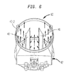
- the illustration of the directions and flow of air are also shown in Figs. 4 and 6 .
- the blades 40 and 41 can be adjusted. This is accomplished through use of an adjustment means 84, as illustrated in Fig. 7 , 8 and 9 and described further below.
- a preferred adjustment means comprises a system wherein the blades 40 and 41 are simultaneously adjustable.
- the blades 40 and 41 are connected to rotatable shafts 122-1 and 122-2, as illustrated in Figs. 3 and 5 .
- the rotatable shafts 122-1 and 122-2 extend through the housing 42 of the balancing damper assembly 26.
- a control knob 90 is provided to adjust rotatable shafts 122-1 and 122-2, such that the blades 40 and 41 can be placed in an open or closed position.
- Control knob 90 turns control stem 92, which is in turn connected to rotatable shafts 122-1 and 122-2.
- Control knob 90 can be rotated in either a clockwise or counter-clockwise direction. This manipulation forces movement of the control stem 92 to shift upwards or downwards (depending on the direction the control knob is turned), thereby causing movement of the rotatable shafts 122-1 and 122-2.
- control knob 90 will cause movement of the rotatable shafts 122-1 and 122-2, such that blades 40 and 41 move towards each other into a closed position.
- rotation of the control knob 90 in a counter-clockwise direction will cause movement of the rotatable shafts 122-1 and 122-2, such that blades 40 and 41 move apart from each other into an open position.
- control knob 90 is capable of adjusting both blades 40 and 41 at the same time.
- the adjustment means may be electronically controlled, either by remote control, a control panel implemented on the balancing damper itself or another part of the furnace assembly. Additionally, the adjustment means may be constructed and arranged so that the blades are individually controlled. In such an embodiment, separate controls may be implemented to independently adjust each blade. Further, the counter-clockwise movement of the control knob 90 may move the blades into a closed position and a clockwise movement of the control knob 90 will move the blades into an open position.
- both the inlet end 80 and outlet end 82 may have circular cross-sections.
- the central portion 48 of the housing 42 preferably has a rectangular cross-section. The rectangular shape of the central portion 48 provides additional room for the two-phase flow to pass between the outer edges 40-1 and 41-2 of the blades 40 and 41, and the inner walls of the housing 42-2.
- the balancing damper assembly 26 has a transition region 49, wherein the balancing damper assembly 26 transitions from a circular to square cross-section at its inlet end 80, and then back to a circular cross-section at its outlet end 82. It should be appreciated that the components of the balancing damper assembly 26 are not limited to any particular geometric configuration.
- the shape and construction of the blades further manipulates the direction and amount of two-phase flow through the balancing damper assembly.
- the blades 40 and 41 are preferably rectangular in shape, but the blades can have various geometric configurations in alternate embodiments.
- the blades 40 and 41 can be attached to the housing in a variety of ways.
- the blades 40 and 41 are welded to rotatable shafts 122-1 and 122-2.
- the blades 40 and 41 can be screwed or nailed to the rotating shafts 122-1 and 122-2.
- an inlet plate 96 and outlet plate 86 connect the balancing damper assembly 26 to the coal pipes 24 and 25.
- the balancing damper assembly may be circular in shape and can be secured to the coal pipes 24 and 25 in a variety of ways.
- inlet plate 96 and outlet plate 86 can be screwed to the coal pipes 24 and 25 through screw holes 86-1 to 86-18 and 96-1 to 96-18 (not all shown) located on the inlet and outlet plates 86 and 96. It should be appreciated that the number of screw holes will depend on the size and strength of the screws utilized.
- the inlet plate 86 and outlet plate 96 can also be attached by rivets, clamps, friction, adhesives, etc. Additionally the balancing damper housing 42 may be directly welded to coal pipes 24 and 25 without the inlet circular plate 96 and outlet circular plate 86.
- a set of turning baffles 130 and 132 are disposed on each of the blades 40 and 41.
- the turning baffles 130 and 132 provide yet another feature of the present invention.
- the turning baffles 130 and 132 further eliminate the occurrences of turbulent eddies in the coal pipe that result in long-term damage to the coal pipes.
- the location of the turning baffles 130 and 132 on the blades 40 and 41 distributes the flow of pulverized fuel and the carrier gas towards the center of the blades 40 and 41 and the center of the balancing damper assembly 26. This ultimately directs the two-phase flow through the center of the coal pipe 25.
- any turbulent eddies that may develop are therefore concentrated at the center of pipe and are harmless to the inner walls of the furnace pipe system.
- Fig. 11 shows a top view of a blade 40 having a set of turning baffles 130 and 132.
Landscapes
- Engineering & Computer Science (AREA)
- General Engineering & Computer Science (AREA)
- Mechanical Engineering (AREA)
- Chemical & Material Sciences (AREA)
- Combustion & Propulsion (AREA)
Abstract
Description
- Many industrial processes require the equal distribution of heterogeneous flows to multiple receptors. For example in the electric utility industry, pulverized coal ("PC") is transported through a pipe (duct) system that connects a grinding mill to one, or more, burners of a furnace. The PC is transported within the pipe system by a carrier gas, e.g., air. Thus, the heterogeneous flow, or stream, is made up of the PC and air (i.e., a two-phase flow or multi-phase flow). Ideally, one grinding mill is capable of supplying one or more such streams to multiple burners (receptors) of the furnace.
- Unfortunately, as a stream moves through a long length of pipe, the solid particles in the stream tend to concentrate together in a pattern generally characterized as being in the shape of a rope strand. This phenomenon is commonly referred to as roping, or leaning. As such, any attempt to further distribute, or split, a stream into multiple streams for transport to respective receptors seldom, if ever, yields equal amounts of PC going to each of the receptors. In other words, when roping occurs in a stream, splitting that stream into multiple streams results in a flow imbalance between the multiple streams. This flow imbalance is also compounded by unequal pressure drops across the coal pipes caused by non-identified pipe length and configurations. Resulting flow imbalances could be on the order of ±30% between the multiple streams.
- Likewise, with respect to receptors fed by multiple sources, roping makes it difficult to combine the flows from these multiple sources such that each of the receptors are supplied with equal flows.
- Various methods and devices have been utilized to obtain more uniform and homogenous two-phase flow through a fuel pipe system, as the flow travels from the coal mill to the furnace. Such methods and devices are implemented at different points downstream of the coal mill. One such method and device is a conventional adjustable orifice, as illustrated in
Fig. 1 . The conventional adjustable orifice can be implemented at any point along the furnace pipe system. Such an adjustable orifice comprisesopposed gate boxes slidable gates pipe 111 frompipe 110 by altering the opening betweengates - To increase the amount of coal and a carrier gas into the
pipe 111, the gates can be retracted into thegate boxes pipe 111, thegates - The use of such an adjustable orifice has disadvantages. The adjustable orifice was initially designed for use in a single-phase flow. As shown in
Fig. 1 , if used in a two-phase system, once the flow passes through the gateway opening,coal eddies 125 are created from streams of coal, which are interrupted as they travel over the top edges 123-1 and 124-1. of thegates gates gate boxes - The present invention relates to an improved furnace system that supplies a uniform flow of fuel and a carrier gas such as through a pipe system to a furnace. Specifically, the present invention is directed to a furnace system having a balancing damper assembly that contains a plurality of adjustable blades. The adjustable blades are constructed and arranged so as to facilitate an efficient and uniform flow of fuel and a carrier gas in a burner assembly.
- In one embodiment of the invention, a balancing damper comprises a housing, with an inlet end and an outlet end, that contains a plurality of blades disposed within the center of the housing. Furthermore, there are at least two blades that are capable of being moved between an open and closed position. This particular arrangement and construction of the blades allows streams of pulverized coal and a carrier gas that enter the balancing damper housing, to travel between the two blades, as well as between the outer edges of the blades and the inner edges of the housing walls.
- In another embodiment, the balancing damper further comprises at least one blade that has at least one turning baffle.
- In accordance with another aspect of this invention, an assembly for use in a furnace system comprises three sections: a burner assembly, a pipe arranged upstream of the burner assembly, and a balancing damper located within the pipe. The balancing damper comprises a housing having an inner and outer wall, at least two blades located within the housing that are capable of being moved between an open and closed position.
- In another embodiment, the assembly for use in a furnace system further comprises a tower distributor. In yet another embodiment, the assembly comprises a fuel injector. In another embodiment, the assembly comprises an air register assembly.
- In accordance with another aspect of this invention, a furnace system is comprised of four components: a furnace, a burner assembly, which delivers pulverized fuel in a carrier gas, a pipe that is arranged upstream of the burner assembly, and a balancing damper located downstream of a fuel source.
- A balancing damper according to the present invention will overcome the shortcomings in the prior art. A balancing damper according to the present invention will allow optimum flow of coal and a carrier gas, while prolonging the life of the pipe system. The design of the present invention reduces the amount of turbulent eddies present in a pipe system by directing any turbulent eddies towards the center of the pipe. This reduces the amount of wear and tear on the interior walls of the pipe. The present design is also advantageous because unlike prior art orifices, it may be positioned in the horizontal or vertical direction without coal piling up downstream of the balancing damper.
- It is therefore, an object of the present invention to provide an assembly for use in a furnace system that will produce a more homogeneous flow of coal in a carrier gas and the efficient and complete combustion of coal in a carrier gas within the furnace burner.
- It is also an object of the present invention to provide a balancing damper for use in a furnace system that will produce a single, laminar, and homogeneous stream.
- It is also an object of the present invention to provide a balancing damper for use in a furnace system that will prolong the life of the pipes carrying a two-phase flow of pulverized coal and a carrier gas.
- Another object of this invention is to provide a balancing damper for use in a furnace system that is capable of being oriented in either the vertical or horizontal position along a furnace pipe assembly.
- Another object of this invention is to provide a balancing damper for use in a furnace assembly that will eliminate the buildup of coal that collects along the pipe.
-
-
Fig. 1 shows a prior art adjustable orifice. -
Fig. 2 is an illustrative block diagram of a furnace system's fuel and primary air circuit according to the present invention. -
Fig. 3 is a cross-sectional view of a balancing damper assembly in accordance with one principal of the invention. -
Fig. 4 is a second cross sectional view of a two-phase flow traveling through the balancing damper assembly. -
Fig. 5 is a top view of the balancing damper assembly ofFig. 3 . -
Fig. 6 is a perspective top view of the balancing damper assembly ofFig. 3 . -
Fig. 7 is another perspective top view of the balancing damper assembly according to the present invention. -
Fig. 8 is a side view of an adjustment means for the balancing damper assembly ofFig. 3 . -
Fig. 9 is a second, enlarged, side view of an adjustment means for the balancing damper assembly. -
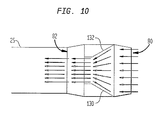
Fig. 10 is a cross-sectional view of a two-phase flow traveling through the balancing damper assembly referenced inFigure 6 . -
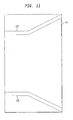
Fig. 11 is a top view of a blade of the balancing damper assembly according to the present invention. - A preferred furnace assembly according to the present invention is illustrated in
Fig. 2 . The furnace assembly comprises acoal mill 20,coal pipes 24, 24-1, 24-2 and 25, a balancingdamper assembly 26, atower distributor 22, afuel injector 28, anair register assembly 30, and aburner zone 32. Streams of fuel, such as pulverized coal, and a carrier gas (e.g., air) originate at thecoal mill 20. The flow passes through atower distributor 22 that helps to provide a balanced two-phase flow of fuel and a carrier gas prior to their entry into acoal pipe 24.Tower distributor 22, such as that disclosed in a related U.S. Application entitled "Tower Distributor" to Vatksy, which is incorporated by reference herein, has an elongated passageway to provide an area for turbulent eddies to settle down and form a more laminar and homogenous flow of fuel and air. Once the flow of pulverized coal and primary air travel through thetower distributor 22, it is distributed among one or more coal pipes, such as represented bypipes 24, 24-1, 24-2 and 25. The coal pipes eventually lead the flow of coal and carrier air into aburner zone 32, where the fuel stream is consumed. For simplicity, the second stream with respect tocoal pipe 24 is only described herein. - During its travel through
coal pipes damper assembly 26, which can be located a predetermined distance downstream from thecoal mill 20. The balancingdamper assembly 26 permits on-line adjustment of resistance in the pipe circuits to optimize pipe-to-pipe coal balance. In doing so, it prolongs the life of thepipes damper assembly 26 is described in greater detail below. - Once the flow of fuel and air passes through the balancing
damper assembly 26, the flow will pass throughcoal pipe 25 that feeds directly intofuel injector 28.Air register assemblies 30 provide a swirl of air that surrounds the fuel injector. This permits adjustment of the flame that results when the fuel and carrier air are injected into theburner zone 32. - The overall effect of the furnace assembly of the present invention is to achieve improved balance of coal and carrier air between coal pipes leaving a mill, while prolonging the life of the furnace assembly components. This ultimately allows a greater percentage of fuel to be burned in the burner zone, thereby reducing the amount of harmful pollutants emitted into the atmosphere and increasing the efficiency of the furnace system.
- It should be noted that in alternative embodiments, the furnace assembly may comprise different variations of the aforementioned system. Certain components of the assembly, such as the tower distributor and air register assembly need not be present for the furnace assembly to function properly. Thus, an alternative furnace assembly may consist of a coal mill, a balancing damper assembly (i.e., an adjustable damper assembly) and fuel injector. Similarly, another furnace assembly may consist of a coal mill, a balancing damper assembly, a fuel injector and an air register assembly.
- In the description that follows, references will be made to
Figs. 3-11 , all of which illustrate various aspects of the invention. A balancingdamper assembly 26 according to the present invention is illustrated inFig. 3 . The balancingdamper assembly 26 preferably has ahousing 42 and twoblades housing 42. The blades respectively have outer edges 40-1 and 41-1 and interior edges 40-2 and 41-2. The balancingdamper assembly 26 may be constructed using steel with various wear-resistant materials, such as metals, certain polymers, ceramic, etc. - The two-phase flow of fuel and air enters the balancing
damper assembly 26 at itsinlet end 80. The fuel flow travels between the inner edges 40-2 and 41-2, as well as between the inner walls 42-2 of thehousing 42 and the outer edges 40-1 and 41-1 of theblades blades outlet end 82 into coal pipe 25 (Fig. 2 ). The illustration of the directions and flow of air are also shown inFigs. 4 and6 . - In order to regulate or alter the flow of air and fuel passing through the balancing
damper assembly 26, theblades Fig. 7 ,8 and 9 and described further below. - A preferred adjustment means comprises a system wherein the
blades blades Figs. 3 and5 . The rotatable shafts 122-1 and 122-2 extend through thehousing 42 of the balancingdamper assembly 26. - As shown in
Figs. 8 and 9 , acontrol knob 90 is provided to adjust rotatable shafts 122-1 and 122-2, such that theblades Control knob 90 turnscontrol stem 92, which is in turn connected to rotatable shafts 122-1 and 122-2.Control knob 90 can be rotated in either a clockwise or counter-clockwise direction. This manipulation forces movement of the control stem 92 to shift upwards or downwards (depending on the direction the control knob is turned), thereby causing movement of the rotatable shafts 122-1 and 122-2. In a preferred embodiment, clockwise rotation ofcontrol knob 90 will cause movement of the rotatable shafts 122-1 and 122-2, such thatblades control knob 90 in a counter-clockwise direction will cause movement of the rotatable shafts 122-1 and 122-2, such thatblades control knob 90 is capable of adjusting bothblades - In an alternative embodiment, the adjustment means may be electronically controlled, either by remote control, a control panel implemented on the balancing damper itself or another part of the furnace assembly. Additionally, the adjustment means may be constructed and arranged so that the blades are individually controlled. In such an embodiment, separate controls may be implemented to independently adjust each blade. Further, the counter-clockwise movement of the
control knob 90 may move the blades into a closed position and a clockwise movement of thecontrol knob 90 will move the blades into an open position. - The direction and amount of two-phase flow through the balancing
damper assembly 26 is further manipulated by the geometric configuration of the balancing damper assembly. As illustrated inFig. 7 , both theinlet end 80 and outlet end 82 may have circular cross-sections. Thecentral portion 48 of thehousing 42 preferably has a rectangular cross-section. The rectangular shape of thecentral portion 48 provides additional room for the two-phase flow to pass between the outer edges 40-1 and 41-2 of theblades damper assembly 26 has atransition region 49, wherein the balancingdamper assembly 26 transitions from a circular to square cross-section at itsinlet end 80, and then back to a circular cross-section at itsoutlet end 82. It should be appreciated that the components of the balancingdamper assembly 26 are not limited to any particular geometric configuration. - The shape and construction of the blades further manipulates the direction and amount of two-phase flow through the balancing damper assembly. As illustrated in
Figs. 3 and6 , theblades - The
blades blades blades - To connect the balancing
damper assembly 26 to thepipes Fig. 7 , aninlet plate 96 andoutlet plate 86 connect the balancingdamper assembly 26 to thecoal pipes coal pipes inlet plate 96 andoutlet plate 86 can be screwed to thecoal pipes outlet plates inlet plate 86 andoutlet plate 96 can also be attached by rivets, clamps, friction, adhesives, etc. Additionally the balancingdamper housing 42 may be directly welded tocoal pipes circular plate 96 and outletcircular plate 86. - In another preferred embodiment, as illustrated in
Figs. 10 and11 , a set of turningbaffles blades Fig. 10 , the location of the turning baffles 130 and 132 on theblades blades damper assembly 26. This ultimately directs the two-phase flow through the center of thecoal pipe 25. Thus, any turbulent eddies that may develop are therefore concentrated at the center of pipe and are harmless to the inner walls of the furnace pipe system.Fig. 11 shows a top view of ablade 40 having a set of turningbaffles - Although the invention herein has been described with reference to particular embodiments, it is to be understood that these embodiments are merely illustrative of the principles and applications of the present invention. It is therefore to be understood that numerous modifications may be made to the illustrative embodiments and that other arrangements may be devised without departing from the spirit and scope of the present invention as defined by the appended claims.
- Further aspects of the invention:
- 1. An assembly for use in a furnace system said assembly comprising:
- (a) a burner assembly;
- (b) a pipe arranged upstream of said burner assembly;
- (c) a balancing damper arranged along said pipe downstream of a fuel source; said balancing damper comprising a housing having an inner wall and an outer wall; and a plurality of blades, each blade having an inner edge and an outer edge disposed within said housing, said plurality of blades being movable between a closed position and an open position.
- 2. The assembly of item 1 further comprising a tower distributor.
- 3. The assembly of item 1 further comprising an air register.
- 4. The assembly of item 1 further comprising a fuel injector.
- 5. The assembly of item 1, wherein said damper housing further comprises:
- (a) an inlet section, said inlet section having a circular shape;
- (b) a central section, said central section having a square shape; and
- (c) an outlet section, said outlet section being square in shape.
- 6. The assembly of item 1, wherein said plurality of blades are rectangular.
- 7. The assembly of item 1, wherein at least one turning baffle is disposed on at least one of said plurality of said blades.
- 8. The assembly of item 1, including an adjustment means for controlling the position of at least one blade.
- 9. The assembly of item 8, wherein said adjustment means comprises a control knob.
- 10. The assembly of item 8, wherein said adjustment means comprises a remote control means.
- 11. A furnace system comprising:
- a furnace;
- a burner assembly for delivering pulverized fuel in a carrier gas;
- a pipe arranged upstream of said burner assembly for permitting the flow of solids in a carrier gas;
- a balancing damper arranged within said pipe downstream of a fuel source; said balancing damper comprising: a housing having an inner wall and an outer wall; and a plurality of blades having an inner edge and an outer edge disposed within said housing, said plurality of blades being movable between a closed position and an open position.
- 12. A balancing damper for use in a furnace system, said balancing damper comprising:
- a housing having an inner wall and an outer wall; and
- a plurality of blades, each blade having an inner edge and an outer edge disposed within said housing, said plurality of blades being movable between a closed position and an open position.
- 13. The balancing damper of item 12, wherein said damper housing further comprises:
- (a) an inlet section, said inlet section having a circular shape;
- (b) a central section, said central section having a square shape; and
- (c) an outlet section, said outlet section being square in shape.
- 14. The balancing damper of item 12, wherein said blades are rectangular.
- 15. The balancing damper of item 12, wherein at least one turning baffle is disposed on at least one of said plurality of blades.
- 16. The balancing damper of item 12, including an adjustment means for controlling the position of at least one blade.
- 17. The balancing damper of item 12, wherein said adjustment means comprises a control knob.
- 18. The balancing damper of item 12, wherein said adjustment means comprises a remote control means.
Claims (6)
- A balancing damper (26) for use in a furnace system, said balancing damper comprising:a housing (42) having an inner wall (42-1,42-2) and an outer wall; anda plurality of blades (40,41), each blade having an inner edge (40-2,41-2) and an outer edge (40-1,41-1) disposed within said housing, said plurality of blades being movable between a closed position and an open position,characterized in that at least one turning baffle (130,132) is disposed on at least one of said plurality of blades (40,41).
- The balancing damper of claim 1, wherein said damper housing (42) further comprises:(a) an inlet section, said inlet section having a circular shape;(b) a central section, said central section having a square shape; and(c) an outlet section, said outlet section being square in shape.
- The balancing damper of claim 1, wherein said blades (40,41) are rectangular.
- The balancing damper of claim 1, including an adjustment means (84) for controlling the position of at least one blade.
- The balancing damper of claim 1, wherein said adjustment means (84) comprises a control knob (90).
- The balancing damper of claim 1, wherein said adjustment means (84) comprises a remote control means.
Applications Claiming Priority (2)
| Application Number | Priority Date | Filing Date | Title |
|---|---|---|---|
| US10/379,621 US7341007B2 (en) | 2003-03-05 | 2003-03-05 | Balancing damper |
| EP04717975.9A EP1604148B1 (en) | 2003-03-05 | 2004-03-05 | Balancing damper |
Related Parent Applications (2)
| Application Number | Title | Priority Date | Filing Date |
|---|---|---|---|
| EP04717975.9 Division | 2004-03-05 | ||
| EP04717975.9A Division EP1604148B1 (en) | 2003-03-05 | 2004-03-05 | Balancing damper |
Publications (2)
| Publication Number | Publication Date |
|---|---|
| EP2674676A2 true EP2674676A2 (en) | 2013-12-18 |
| EP2674676A3 EP2674676A3 (en) | 2014-09-03 |
Family
ID=32926713
Family Applications (2)
| Application Number | Title | Priority Date | Filing Date |
|---|---|---|---|
| EP13183615.7A Withdrawn EP2674676A3 (en) | 2003-03-05 | 2004-03-05 | Balancing damper |
| EP04717975.9A Expired - Lifetime EP1604148B1 (en) | 2003-03-05 | 2004-03-05 | Balancing damper |
Family Applications After (1)
| Application Number | Title | Priority Date | Filing Date |
|---|---|---|---|
| EP04717975.9A Expired - Lifetime EP1604148B1 (en) | 2003-03-05 | 2004-03-05 | Balancing damper |
Country Status (8)
| Country | Link |
|---|---|
| US (1) | US7341007B2 (en) |
| EP (2) | EP2674676A3 (en) |
| JP (1) | JP4624989B2 (en) |
| KR (1) | KR20050112094A (en) |
| AU (1) | AU2004217438B2 (en) |
| CA (1) | CA2517475A1 (en) |
| PL (1) | PL1604148T3 (en) |
| WO (1) | WO2004079261A2 (en) |
Families Citing this family (19)
| Publication number | Priority date | Publication date | Assignee | Title |
|---|---|---|---|---|
| JP4659300B2 (en) | 2000-09-13 | 2011-03-30 | 浜松ホトニクス株式会社 | Laser processing method and semiconductor chip manufacturing method |
| CN101335235B (en) | 2002-03-12 | 2010-10-13 | 浜松光子学株式会社 | Method for dicing substrate |
| CN1328002C (en) | 2002-03-12 | 2007-07-25 | 浜松光子学株式会社 | Cutting method for workpiece |
| TWI520269B (en) | 2002-12-03 | 2016-02-01 | 濱松赫德尼古斯股份有限公司 | Cutting method of semiconductor substrate |
| FR2852250B1 (en) | 2003-03-11 | 2009-07-24 | Jean Luc Jouvin | PROTECTIVE SHEATH FOR CANNULA, AN INJECTION KIT COMPRISING SUCH ANKLE AND NEEDLE EQUIPPED WITH SUCH ANKLE |
| DE60315515T2 (en) | 2003-03-12 | 2007-12-13 | Hamamatsu Photonics K.K., Hamamatsu | LASER PROCESSING PROCEDURES |
| JP4563097B2 (en) | 2003-09-10 | 2010-10-13 | 浜松ホトニクス株式会社 | Semiconductor substrate cutting method |
| TW200523506A (en) * | 2003-12-10 | 2005-07-16 | Kiyoharu Michimae | A combustion apparatus for disposal of a dry distillation gas |
| JP4509578B2 (en) | 2004-01-09 | 2010-07-21 | 浜松ホトニクス株式会社 | Laser processing method and laser processing apparatus |
| US8544499B2 (en) * | 2007-02-09 | 2013-10-01 | Wark E. Rickey | Variable orifice for particulate coal conduit |
| JP4814137B2 (en) * | 2007-03-26 | 2011-11-16 | 三菱重工業株式会社 | Pulverized coal concentration adjustment device |
| US8277116B2 (en) * | 2007-05-07 | 2012-10-02 | The Boeing Company | Fluidic mixer with controllable mixing |
| US20100034049A1 (en) * | 2008-08-06 | 2010-02-11 | Nicholas William Ferri | Adjustable Diffusing Coal Valve |
| JP2010062683A (en) * | 2008-09-01 | 2010-03-18 | Smk Corp | Remote control transmitter |
| US9657944B2 (en) | 2010-09-09 | 2017-05-23 | General Electric Technology Gmbh | Assembly for fossil fuel distribution |
| CN103403450B (en) * | 2010-09-09 | 2016-08-17 | 通用电器技术有限公司 | Assembly for Fossil fuel distribution |
| SE536195C2 (en) * | 2011-10-12 | 2013-06-18 | Ecomb Ab Publ | Supply device for combustion chamber and method therefore |
| KR101317937B1 (en) * | 2012-01-31 | 2013-10-16 | (주)파워엔지니어링 | Coal supplying control apparatus for thermal power plant boiler |
| KR102240464B1 (en) * | 2020-04-02 | 2021-04-13 | 김상일 | Swing gate type Adjustable Orifice Valve unit of pulverized coal supply control system of thermal power plant |
Family Cites Families (26)
| Publication number | Priority date | Publication date | Assignee | Title |
|---|---|---|---|---|
| US1477824A (en) | 1923-12-18 | grindle | ||
| US1316439A (en) | 1919-09-16 | Dampeb | ||
| US993381A (en) | 1910-05-21 | 1911-05-30 | Frank Ditchfield | Pipe-damper. |
| US1100634A (en) | 1913-08-11 | 1914-06-16 | Hugh L Turner | Ventilator. |
| US1708496A (en) | 1925-06-12 | 1929-04-09 | Combustion Eng Corp | Pulverized-fuel burner |
| US1747522A (en) * | 1926-02-01 | 1930-02-18 | Forges & Acieries Commercy | Heating apparatus employing powdered fuel |
| US2079420A (en) | 1930-06-23 | 1937-05-04 | Grindle Fuel Equipment Co | Burner for firing furnaces with powdered fuel |
| GB637319A (en) * | 1947-07-01 | 1950-05-17 | Thompson John Water Tube Boilers Ltd | Improvements in or relating to pulverised fuel supply systems |
| US3002472A (en) | 1958-04-21 | 1961-10-03 | Riley Stoker Corp | Comminution system for wet solid materials |
| US3267891A (en) | 1964-10-07 | 1966-08-23 | Babcock & Wilcox Co | Distributor for particle-form material |
| US3524418A (en) | 1969-05-02 | 1970-08-18 | William C Cowan | Industrial burner draught regulating mechanism |
| GB2132318B (en) * | 1982-12-01 | 1986-03-12 | Kilard Co | Valve |
| US4459922A (en) | 1983-01-24 | 1984-07-17 | Combustion Engineering, Inc. | Externally adjustable pipe orifice assembly |
| US4477248A (en) * | 1983-08-04 | 1984-10-16 | Dulac Robert R | Oil burner shutter |
| JPS60221616A (en) * | 1984-04-18 | 1985-11-06 | Babcock Hitachi Kk | Pulverized material supplying device |
| US4602571A (en) * | 1984-07-30 | 1986-07-29 | Combustion Engineering, Inc. | Burner for coal slurry |
| US4806056A (en) * | 1986-07-07 | 1989-02-21 | Waste Recovery, Inc. | Modular fuel metering apparatus and method for use thereof |
| JP2547550B2 (en) * | 1986-10-18 | 1996-10-23 | バブコツク日立株式会社 | Pulverized coal combustion method and apparatus |
| JPS63271019A (en) * | 1987-04-27 | 1988-11-08 | Hitachi Ltd | Pulverized coal boiler operating method and pulverized coal boiler system |
| JP2776572B2 (en) * | 1989-07-17 | 1998-07-16 | バブコツク日立株式会社 | Pulverized coal burner |
| US5010827A (en) * | 1990-05-08 | 1991-04-30 | Wyerehaeuser Company | Apparatus for detecting carryover particles in the interior of a furnace |
| US5593131A (en) | 1995-11-13 | 1997-01-14 | Db Riley, Inc. | Variable orifice plate for coal pipes |
| US5771823A (en) * | 1996-01-31 | 1998-06-30 | Aep Resources Service Company | Method and apparatus for reducing NOx emissions from a multiple-intertube pulverized-coal burner |
| JP2778945B2 (en) * | 1996-04-16 | 1998-07-23 | 三菱重工業株式会社 | Granular material flow control device |
| JPH10232018A (en) * | 1997-02-20 | 1998-09-02 | Ishikawajima Harima Heavy Ind Co Ltd | Boiler equipment |
| US6799525B2 (en) * | 2002-09-13 | 2004-10-05 | General Electric Company | Automatic coal damper |
-
2003
- 2003-03-05 US US10/379,621 patent/US7341007B2/en not_active Expired - Fee Related
-
2004
- 2004-03-05 AU AU2004217438A patent/AU2004217438B2/en not_active Ceased
- 2004-03-05 EP EP13183615.7A patent/EP2674676A3/en not_active Withdrawn
- 2004-03-05 WO PCT/US2004/006647 patent/WO2004079261A2/en not_active Ceased
- 2004-03-05 CA CA002517475A patent/CA2517475A1/en not_active Abandoned
- 2004-03-05 EP EP04717975.9A patent/EP1604148B1/en not_active Expired - Lifetime
- 2004-03-05 PL PL04717975T patent/PL1604148T3/en unknown
- 2004-03-05 JP JP2006509138A patent/JP4624989B2/en not_active Expired - Fee Related
- 2004-03-05 KR KR1020057016501A patent/KR20050112094A/en not_active Withdrawn
Non-Patent Citations (1)
| Title |
|---|
| None |
Also Published As
| Publication number | Publication date |
|---|---|
| CA2517475A1 (en) | 2004-09-16 |
| US7341007B2 (en) | 2008-03-11 |
| EP1604148B1 (en) | 2013-09-11 |
| JP2006520457A (en) | 2006-09-07 |
| JP4624989B2 (en) | 2011-02-02 |
| AU2004217438A1 (en) | 2004-09-16 |
| US20040173128A1 (en) | 2004-09-09 |
| EP1604148A4 (en) | 2011-05-11 |
| KR20050112094A (en) | 2005-11-29 |
| EP1604148A2 (en) | 2005-12-14 |
| AU2004217438B2 (en) | 2009-04-09 |
| EP2674676A3 (en) | 2014-09-03 |
| WO2004079261A2 (en) | 2004-09-16 |
| WO2004079261A3 (en) | 2005-02-03 |
| PL1604148T3 (en) | 2014-02-28 |
Similar Documents
| Publication | Publication Date | Title |
|---|---|---|
| EP1604148B1 (en) | Balancing damper | |
| JP6016395B2 (en) | Coal flow distributor and distributor | |
| US6789488B2 (en) | Adjustable flow control elements for balancing pulverized coal flow at coal pipe splitter junctions | |
| US8919670B2 (en) | Injection lance with variable swirl | |
| US8657221B2 (en) | Roller mill structure | |
| RU2546343C2 (en) | Burner for pulverised and/or granulated fuel with alternating swirl | |
| JPH0515924B2 (en) | ||
| US7013815B2 (en) | Adjustable air foils for balancing pulverized coal flow at a coal pipe splitter junction | |
| US8104412B2 (en) | Deflector device for coal piping systems | |
| US20110239915A1 (en) | Adjustable Diffusing Coal Valve | |
| CN107131518A (en) | A kind of middle warehouse formula medium-speed pulverizer pressurized direct pulverizing coal system | |
| FI94152B (en) | Methods and apparatus for the oxidation of fuel in powder form with two gases with different oxygen levels | |
| KR20080080490A (en) | Online adjustable coal flow distribution device | |
| JPS58193006A (en) | Burner for ground coke | |
| JPS58224207A (en) | Pulverized coal firing equipment | |
| US6988452B2 (en) | Tower distributor assembly | |
| CN103392096A (en) | Tower distributors in coal-fired power plants | |
| US20030205183A1 (en) | Method and apparatus for promoting biaxially uniform particle size distribution in an airstream containing coal particles of mixed sizes | |
| JP2020041776A (en) | Distributor of solid/gas two-phase flow | |
| JPH0262770B2 (en) | ||
| JPH0942649A (en) | Pulverized coal transport pipe bend | |
| MXPA98002329A (en) | Burner for the combustion of a pulveriz fuel | |
| EP3469261A1 (en) | Burner |
Legal Events
| Date | Code | Title | Description |
|---|---|---|---|
| PUAI | Public reference made under article 153(3) epc to a published international application that has entered the european phase |
Free format text: ORIGINAL CODE: 0009012 |
|
| AC | Divisional application: reference to earlier application |
Ref document number: 1604148 Country of ref document: EP Kind code of ref document: P |
|
| AK | Designated contracting states |
Kind code of ref document: A2 Designated state(s): AT BE BG CH CY CZ DE DK EE ES FI FR GB GR HU IE IT LI LU MC NL PL PT RO SE SI SK TR |
|
| RIN1 | Information on inventor provided before grant (corrected) |
Inventor name: VATSKY, JOEL |
|
| PUAL | Search report despatched |
Free format text: ORIGINAL CODE: 0009013 |
|
| AK | Designated contracting states |
Kind code of ref document: A3 Designated state(s): AT BE BG CH CY CZ DE DK EE ES FI FR GB GR HU IE IT LI LU MC NL PL PT RO SE SI SK TR |
|
| RIC1 | Information provided on ipc code assigned before grant |
Ipc: F16K 1/22 20060101ALI20140725BHEP Ipc: F23K 3/02 20060101AFI20140725BHEP |
|
| STAA | Information on the status of an ep patent application or granted ep patent |
Free format text: STATUS: THE APPLICATION IS DEEMED TO BE WITHDRAWN |
|
| 18D | Application deemed to be withdrawn |
Effective date: 20150304 |