EP2674649B1 - Dispositifs de distribution pneumatique et leurs réglages - Google Patents
Dispositifs de distribution pneumatique et leurs réglages Download PDFInfo
- Publication number
- EP2674649B1 EP2674649B1 EP13171519.5A EP13171519A EP2674649B1 EP 2674649 B1 EP2674649 B1 EP 2674649B1 EP 13171519 A EP13171519 A EP 13171519A EP 2674649 B1 EP2674649 B1 EP 2674649B1
- Authority
- EP
- European Patent Office
- Prior art keywords
- distribution
- longitudinal axis
- bayonet coupling
- intermediate element
- seals
- Prior art date
- Legal status (The legal status is an assumption and is not a legal conclusion. Google has not performed a legal analysis and makes no representation as to the accuracy of the status listed.)
- Active
Links
Images




Classifications
-
- F—MECHANICAL ENGINEERING; LIGHTING; HEATING; WEAPONS; BLASTING
- F16—ENGINEERING ELEMENTS AND UNITS; GENERAL MEASURES FOR PRODUCING AND MAINTAINING EFFECTIVE FUNCTIONING OF MACHINES OR INSTALLATIONS; THERMAL INSULATION IN GENERAL
- F16K—VALVES; TAPS; COCKS; ACTUATING-FLOATS; DEVICES FOR VENTING OR AERATING
- F16K11/00—Multiple-way valves, e.g. mixing valves; Pipe fittings incorporating such valves
- F16K11/02—Multiple-way valves, e.g. mixing valves; Pipe fittings incorporating such valves with all movable sealing faces moving as one unit
- F16K11/06—Multiple-way valves, e.g. mixing valves; Pipe fittings incorporating such valves with all movable sealing faces moving as one unit comprising only sliding valves, i.e. sliding closure elements
- F16K11/065—Multiple-way valves, e.g. mixing valves; Pipe fittings incorporating such valves with all movable sealing faces moving as one unit comprising only sliding valves, i.e. sliding closure elements with linearly sliding closure members
- F16K11/07—Multiple-way valves, e.g. mixing valves; Pipe fittings incorporating such valves with all movable sealing faces moving as one unit comprising only sliding valves, i.e. sliding closure elements with linearly sliding closure members with cylindrical slides
- F16K11/0712—Multiple-way valves, e.g. mixing valves; Pipe fittings incorporating such valves with all movable sealing faces moving as one unit comprising only sliding valves, i.e. sliding closure elements with linearly sliding closure members with cylindrical slides comprising particular spool-valve sealing means
-
- F—MECHANICAL ENGINEERING; LIGHTING; HEATING; WEAPONS; BLASTING
- F16—ENGINEERING ELEMENTS AND UNITS; GENERAL MEASURES FOR PRODUCING AND MAINTAINING EFFECTIVE FUNCTIONING OF MACHINES OR INSTALLATIONS; THERMAL INSULATION IN GENERAL
- F16K—VALVES; TAPS; COCKS; ACTUATING-FLOATS; DEVICES FOR VENTING OR AERATING
- F16K11/00—Multiple-way valves, e.g. mixing valves; Pipe fittings incorporating such valves
- F16K11/02—Multiple-way valves, e.g. mixing valves; Pipe fittings incorporating such valves with all movable sealing faces moving as one unit
- F16K11/06—Multiple-way valves, e.g. mixing valves; Pipe fittings incorporating such valves with all movable sealing faces moving as one unit comprising only sliding valves, i.e. sliding closure elements
- F16K11/065—Multiple-way valves, e.g. mixing valves; Pipe fittings incorporating such valves with all movable sealing faces moving as one unit comprising only sliding valves, i.e. sliding closure elements with linearly sliding closure members
- F16K11/07—Multiple-way valves, e.g. mixing valves; Pipe fittings incorporating such valves with all movable sealing faces moving as one unit comprising only sliding valves, i.e. sliding closure elements with linearly sliding closure members with cylindrical slides
- F16K11/0704—Multiple-way valves, e.g. mixing valves; Pipe fittings incorporating such valves with all movable sealing faces moving as one unit comprising only sliding valves, i.e. sliding closure elements with linearly sliding closure members with cylindrical slides comprising locking elements
-
- F—MECHANICAL ENGINEERING; LIGHTING; HEATING; WEAPONS; BLASTING
- F16—ENGINEERING ELEMENTS AND UNITS; GENERAL MEASURES FOR PRODUCING AND MAINTAINING EFFECTIVE FUNCTIONING OF MACHINES OR INSTALLATIONS; THERMAL INSULATION IN GENERAL
- F16K—VALVES; TAPS; COCKS; ACTUATING-FLOATS; DEVICES FOR VENTING OR AERATING
- F16K27/00—Construction of housing; Use of materials therefor
- F16K27/04—Construction of housing; Use of materials therefor of sliding valves
- F16K27/041—Construction of housing; Use of materials therefor of sliding valves cylindrical slide valves
Definitions
- the power of the compressed air for the cylinders and motors must be checked.
- the distributor located between the pneumatic energy source and the actuator performs this function.
- This pre-actuator is associated with a jack and its size and type are functions of this jack.
- drawer dispensers In drawer dispensers, several construction technologies can be used.
- a first solution is given in GB 1021500 and US 3303855 which describe the construction and operation of a distributor with static elastomeric seals on the dispensing body.
- the various forms of joints concurrent with dynamic sealing with the mobile shutter slide are declined in different patents such as DE 19603719 , GB 2309753 , US 5711535 , DE 102005019698 and EP 1284379 .
- US 5609343 describes the construction and operation of a distributor with elastomeric seals integral with the mobile distribution drawer.
- the various forms of concurrent dynamic sealing joints being declined in the patents EP 0866252 and EP 0916879 .
- the object of the invention is, above all, to propose a solution to the problem mentioned above.
- Requirement DE 42 24 180 A1 discloses a dispenser arrangement wherein a stack of seals is disposed in a housing of the dispenser body.
- DE 42 24 180 does not disclose locking means for adjusting a stress exerted along the longitudinal axis on the seals, which would for example compensate manufacturing tolerances during the establishment of this locking means.
- FR 2,474,633 discloses seals spaced apart from each other in the longitudinal direction, being held by bearing rings interconnected to form a one-piece member.
- the support rings do not make it possible to exert a greater or lesser longitudinal stress on the joints, a constraint that could be useful to compensate for manufacturing tolerances, for example.
- GB 1 224 241 relates to a valve dispenser.
- CH 393 015 describes a dispenser whose body is closed at one end by a threaded plug and whose drawer carries annular seals.
- a pneumatic dispensing device comprising a dispensing body and a movable slide valve guided in translation along a longitudinal axis in the dispensing body, is characterized in that at least one intermediate element is interposed radially between the body of the distribution and the movable slide valve, a locking means closing an orifice provided in the dispensing body for introducing into the distribution body of the intermediate element along the longitudinal axis.
- the device can be built according to two different architectures.
- the device may comprise a common distribution body associated with an alignment of multifunctional O-rings interposed spacers (half-rings) allowing an optimum flow and a movable drawer.
- the device may comprise a common distribution body associated with a jacket and a movable drawer, the latter two parts providing a sliding seal "metal-metal”.
- the locking means can exert a stress on the intermediate element along the longitudinal axis.
- the locking means can be made in one piece called bayonet.
- the distribution body and the control boxes are common to both construction technologies and adapted to either the monostable or bistable cylinder control single or double effects.
- An alignment of seals and spacers, forming the intermediate element, is interposed radially between the dispensing body and the movable shutter slide, said alignment being pre-loaded along the longitudinal axis so as to allow adjustment of the pressure dynamic sliding contact between the seals and the drawer.
- the seals may be able to provide static sealing between the body and the spacers by cooperating with particular shapes provided in the spacers.
- the particular shape may be able to ensure equipartition of the pre-load on the joints.
- This pre-charge has the advantage of compressing axially and uniformly each seal of the distribution line. This then results in a radial deformation uniformly distributed around the internal diameter of each seal, the effect of which is to compress all the joints on the drawer. This pre-charge is calculated to ensure dynamic sealing with the drawer, while limiting their compression to optimize the life of the product. Due to the shape of the multifunctional seal and the counter-form of the spacers, the pre-charge also contributes to the static seal between each seal and the dispensing body.
- the device according to the invention uses seals of the family of those described in the joint publication of the LRCCP and ASCO JOUCOMATIC SA France P.ROUMAGNAC, D. HUBERT, "Simulations and tests on a distributor of automation pneumatic. LRCCP technical day at CEAT Toulouse, 13 September 2000 ".
- a bayonet according to the invention single piece, simple and inexpensive, is a solution to this problem.
- the setting of the line of distribution is achieved by the insertion of this bayonet in the body of the distributor and the support on the distribution line, a second bayonet can be placed in the same way, at the other end of the distribution line.
- the position of the bayonet in the body is maintained in a single operation, by angular rotation of the bayonet. During this angular rotation, triangular profiles present in the body are inserted into the conjugate profiles of the projecting parts of the bayonet to ensure locking in position.
- the invention describes the use of spacers and multi-functional joints whose shapes are optimized to allow the homogeneous distribution of the preload between joints, which offers a certain advantage over the scientific publication of the LRCCP of September 2000.
- the intermediate element can also be made in the form of a metal sleeve in the case of a so-called metal-metal solution.
- shocks can occur and damage the elements of the device. It is possible to implement a damper housed and centered in a cavity of the dispensing body.
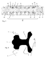
- FIG. 3 a pneumatic dispensing device with static elastomeric seals on the body.
- the device comprises a distribution line 18 equipped with revolution joints 1 ensuring a seal between the inlet and outlet channels 19 of the pneumatic distributor and relative to the outside.
- Spacers 2 are placed between the joints 1 so as to position and hold them in position.
- a bayonet 4 is positioned in a bore 13 of the body 6. The bayonet 4 can be positioned freely or abutting against the shoulder 5 of the body 6 and locked by angular rotation.
- a stack of pre-assembled joints and spacers is then introduced through a sleeve and allowing the equi-distribution of the axial pre-load force.
- the equipartition principle of this axial pre-load is based not only on the shape of the seals 1 and against the form given by the spacers 2, but also the coefficients of friction between the distribution body 6 on the one hand, the spacers 2 on the other hand, the feet of the joints 1.
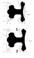
- the figure 4 shows the first phase of the assembly of the spacers 2 with the joints 1 and the beginning of the installation in the sleeve 28.
- the figure 5 shows the end of the set up of the cuff.
- the figure 6 gives the appearance of the spacer joint assembly in the assembly sleeve and introduction into the dispensing body. The sleeve is then extracted and a calibrated rod of the same diameter as the drawer is then introduced as illustrated. figure 7 .
- the normal forces of contact between the feet of the joints and the distribution body are such that they allow the sliding of the joints during the setting in precharge axial ( figure 8 ) and to distribute this effort evenly over the entire stack.
- the calibrated rod is then removed, a second bayonet 14 is then locked in position by angular rotation.
- a drawer 17 is then inserted in the center of the distribution line 18.
- End spacers 3 and 16 make it possible to dissociate the end joints of the respective bayonets 4 and 14.
- the pistons 20, 21, housed in the control boxes 22, can be brought into contact with the slide 17.
- the embodiment which has been described is of the bistable distributor type and uses two pistons.
- the dispenser uses only one piston housed in the control box and the return to the airless position uses a spring housed between the drawer and the other control box .
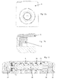
- bayonet locking The principle of bayonet locking (s) is more particularly illustrated figure 10 .
- angular sectors 7 have been provided with one or more claws 12 as illustrated figure 9 . Between these sectors, recesses 8 allow insertion of the complementary portions 9 of the bayonet 4.
- recesses 10 are provided on the bayonet 4.
- the bayonet 4 is rotated by inserting a suitable tool into the cavity 11 of the bayonet 4. During this rotation, the profiles 12 of the angular sectors 7 of the body 8 come into interference with the projecting parts 9 bayonet 4 thus ensuring the locking by plastic deformation of the bayonet 4 ( figures 11 , 12 ) and maintaining compression of the seals 1 in the distribution line 18.
- a pneumatic metal-metal dispensing device is illustrated in the figure 13 and comprises a metal jacket 23 inserted into the body 6, the seal between the body 6 and the metal jacket 23 being provided by the static seals 24.
- the two positions of the movable spool 25 alternately provide control of the jack.
- a damper 26 is centered and housed in the profiled cavity 8 of the body 6, and a locking damper 27 at the other end of the dispensing device is centered and housed identically to the previous one.
- These two dampers are made of an elastic and plastic material (thermoplastic polymer, polyacetal type).
- dampers 26 and 27 replace the bayonets 4 in the housings provided in the body 6 for the bayonets 4. In this way no modification of the body 6 is necessary to go from a use with joints to a use metal-metal.
- the dampers 26 and 27 are more massive than the bayonets 4 and exploit the maximum available space to optimize their ability to absorb shocks.
- control boxes 22 of the construction technology with elastomer seals.
- the body 6 and the control boxes 22 can therefore be completely interchangeable between the two technologies.
Landscapes
- Engineering & Computer Science (AREA)
- General Engineering & Computer Science (AREA)
- Mechanical Engineering (AREA)
- Containers And Packaging Bodies Having A Special Means To Remove Contents (AREA)
- Coating Apparatus (AREA)
- Sealing Devices (AREA)
Description
- La puissance de l'air comprimé destinée aux vérins et moteurs doit être contrôlée. Le distributeur situé entre la source d'énergie pneumatique et l'actionneur remplit cette fonction. Ce pré actionneur est associé à un vérin et sa taille et son type sont fonctions de ce vérin.
- Dans les distributeurs à tiroirs, plusieurs technologies de construction peuvent être employées.
- Une première solution est donnée dans
GB 1021500 US 3303855 qui décrivent la construction et le fonctionnement d'un distributeur avec joints élastomères statiques sur le corps de distribution. Les différentes formes de joints concourantes à l'étanchéité dynamique avec le tiroir obturateur mobile sont déclinées dans différents brevets tels queDE 19603719 ,GB 2309753 US 5711535 ,DE 102005019698 etEP 1284379 . - En alternative
US 5609343 décrit la construction et le fonctionnement d'un distributeur avec joints élastomères solidaires du tiroir mobile de distribution. Les différentes formes de joints concourantes à l'étanchéité dynamiques étant déclinées dans les brevetsEP 0866252 etEP 0916879 . - Enfin
US 6164323 décrit la construction et le fonctionnement d'un système de distribution dont l'étanchéité dynamique est obtenue sans l'aide de joint élastomère, simplement par ajustement précis entre le tiroir et la chemise, dite étanchéité métal-métal. - Ces trois solutions sont très spécifiques et il n'est actuellement pas possible de changer de solution pour une autre.
- Les solutions utilisant des joints permettent une bonne étanchéité au détriment de la durée de vie tandis que les solutions sans joint élastomère, dites métal-métal augmentent la durée de vie du distributeur mais génèrent un débit de fuite.
- L'invention a pour but, surtout, de proposer une solution au problème ci-dessus mentionné.
- La demande
DE 42 24 180 A1 divulgue un agencement de distributeur dans lequel un empilement de joints est disposé dans un logement du corps du distributeur. - Ces joints sont traversés par le tiroir, axialement mobile dans le corps du distributeur.
- Cette demande est silencieuse sur la manière dont le corps est fermé à ses extremités.
- En particulier,
DE 42 24 180 ne divulgue pas de moyen de verrouillage permettant un réglage d'une contrainte exercée suivant l'axe longitudinal sur les joints, qui permettrait par exemple de compenser des tolérance de fabrication lors de la mise en place de ce moyen de verrouillage. -
FR 2 474 633 -
GB 1 224 241 -
CH 393 015 - Selon l'invention, un dispositif de distribution pneumatique comprenant un corps de distribution et un tiroir obturateur mobile guidé en translation suivant un axe longitudinal dans le corps de distribution, est caractérisé en ce que au moins un élément intermédiaire est interposé radialement entre le corps de distribution et le tiroir obturateur mobile, un moyen de verrouillage fermant un orifice prévu dans le corps de distribution permettant l'introduction dans le corps de distribution de l'élément intermédiaire suivant l'axe longitudinal.
- Le dispositif peut être construit suivant deux architectures différentes. Le dispositif peut comprendre un corps commun de distribution associé avec un alignement de joints toriques multifonctionnels intercalés d'entretoises (demi-bagues) autorisant un débit optimum et d'un tiroir mobile.
- En variante le dispositif peut comprendre un corps commun de distribution associé à une chemise et un tiroir mobile, ces deux dernières parties assurant une étanchéité glissante « métal-métal ».
- Ces deux dispositions ne sont pas limitatives par rapport à l'application d'un dispositif de distribution avec joints élastomères solidaires du tiroir mobile qui n'est pas décrite ici.
- Le moyen de verrouillage peut exercer une contrainte sur l'élément intermédiaire suivant l'axe longitudinal. Le moyen de verrouillage peut être réalisé en une seule pièce dite baïonnette.
- Avantageusement, de par l'utilisation du moyen d'assemblage par baïonnette, un ou plusieurs, il est permis que le corps de distribution et les boitiers de commande soient communs aux deux technologies de construction et adaptés soit à la commande monostable ou bistable de vérins simple ou double effets.
- Un alignement de joints et d'entretoises, formant l'élément intermédiaire, est interposé radialement entre le corps de distribution et le tiroir obturateur mobile, ledit alignement étant pré-chargé suivant l'axe longitudinal de manière à permettre l'ajustement de la pression de contact de l'étanchéité dynamique glissante entre les joints et le tiroir.
- Les joints peuvent être aptes à assurer l'étanchéité statique entre le corps et les entretoises en coopérant avec des formes particulières prévues dans les entretoises.
- La forme particulière peut être apte à assurer une équipartition de la pré-charge sur les joints.
- Cette pré-charge a pour intérêt de comprimer axialement et uniformément chaque joint de la ligne de distribution. Il en résulte alors une déformation radiale, uniformément répartie autour du diamètre interne de chaque joint, dont l'effet est de venir comprimer l'ensemble des joints sur le tiroir. Cette pré-charge est calculée de façon à assurer l'étanchéité dynamique avec le tiroir, tout en limitant leur compression pour optimiser la durée de vie du produit. De par la forme du joint multifonctionnel et de la contre forme des entretoises la pré-charge participe aussi à l'étanchéité statique entre chaque joint et le corps de distribution.
- Le dispositif selon l'invention utilise des joints de la famille de ceux décrits dans la publication conjointe du LRCCP et de la société ASCO JOUCOMATIC S.A France de P.ROUMAGNAC, D. HUBERT, « Simulations et essais sur un joint de distributeur d'automatisme pneumatique. Journée technique LRCCP au CEAT Toulouse, 13 septembre 2000 ».
- L'une des difficultés de ce type de réglage, appliqué aux distributeurs pneumatiques, est de verrouiller et de maintenir dans le temps la valeur de pré-charge ainsi appliquée sur les joints, tout en limitant le nombre de pièces nécessaires lors de son montage et de sa mise en fonction par conséquent de réduire le coût global de cette fonction, tout en améliorant le ratio encombrement / débit d'air.
- L'utilisation d'une baïonnette selon l'invention, pièce unique, simple et peu onéreuse, est une solution à ce problème. Le réglage de la ligne de distribution est réalisé par l'insertion de cette baïonnette dans le corps du distributeur et l'appui sur la ligne de distribution, une deuxième baïonnette pouvant être placée de la même façon, à l'autre extrémité de la ligne de distribution. Le maintien en position de la baïonnette dans le corps est réalisé en une seule opération, par rotation angulaire de cette baïonnette. Lors de cette rotation angulaire, des profils triangulaires présents dans le corps viennent s'insérer dans les profils conjugués des parties saillantes de la baïonnette permettant d'assurer un verrouillage en position.
- D'autre part, l'invention décrit l'utilisation d'entretoises et de joints multi-fonctionnels dont les formes sont optimisées pour permettre la répartition homogène de la pré-charge entre joints, qui offre un avantage certain par rapport à la publication scientifique du LRCCP de septembre 2000.
- L'élément intermédiaire peut également être réalisé sous la forme d'un manchon métallique dans le cas d'une solution dite métal-métal.
- Dans ce cas des chocs peuvent intervenir et endommager les éléments du dispositif. Il est possible de mettre en place un amortisseur logé et centré dans une cavité du corps de distribution.
- D'autres caractéristiques et avantages de l'invention apparaîtront dans la description qui suit d'un mode de réalisation d'alimentation d'un vérin double effet avec distributeur bistable avec référence aux dessins annexés mais qui n'a aucun caractère limitatif. Sur ces dessins :
- La
figure 1 est un schéma illustrant l'alimentation d'un vérin simple effet, avec distributeur monostable. - La
figure 2 est un schéma illustrant l'alimentation d'un vérin double effet avec distributeur bistable. - La
figure 3 illustre une ligne de distribution d'un distributeur pneumatique selon l'invention, des joints élastomères étant prévus sur le corps. - Les
figures 4 ,5 ,6 ,7, 8 illustrent la progressivité du serrage des joints sur le corps permettant l'équipartition de la pré-charge. - La
figure 9 illustre la cavité profilée dans le corps du distributeur pneumatique afin de recevoir la baïonnette. - La
figure 10 illustre une baïonnette. - Les
figures 11 illustrent une baïonnette logée dans le corps du distributeur. - Les
figures 12 illustrent une baïonnette insérée et verrouillée dans le corps du distributeur. - La
figure 13 illustre une ligne de distribution d'un distributeur pneumatique à tiroir de technologie dite métal-métal qui ne fait pas partie de l'invention. - On peut voir
figure 3 un dispositif de distribution pneumatique à joints élastomères statiques sur le corps. Le dispositif comprend une ligne de distribution 18 équipée de joints de révolution 1 assurant une étanchéité entre les canaux d'entrée et de sortie 19 du distributeur pneumatique et par rapport à l'extérieur. - Des entretoises 2 sont placées entre les joints 1 de façon à les positionner et les maintenir en position. Une baïonnette 4 est positionnée dans un alésage 13 du corps 6. La baïonnette 4 peut être positionnée librement ou en butée contre l'épaulement 5 du corps 6 puis verrouillée par rotation angulaire. On introduit alors un empilage de joints et d'entretoises préassemblés au travers d'une manchette et permettant l'équi-répartition de l'effort de pré-charge axiale.
- Le principe d'équipartition de cette pré-charge axiale repose non seulement sur la forme des joints 1 et de la contre forme donnée par les entretoises 2, mais aussi des coefficients de frottement entre le corps de distribution 6 d'une part, les entretoises 2 d'autre part, les pieds des joints 1. La
figure 4 montre la première phase de l'assemblage des entretoises 2 avec les joints 1 et le début de la mise en place dans la manchette 28. - La
figure 5 montre la fin de la mise en place de la manchette. Lafigure 6 donne l'allure de l'assemblage joint entretoise dans la manchette d'assemblage et introduction dans le corps de distribution. La manchette est alors extraite et une pige calibrée de même diamètre que le tiroir est alors introduite comme illustréfigure 7 . - Les forces normales de contact entre les pieds des joints et le corps de distribution sont telles qu'elles permettent le glissement des joints lors de la mise en pré-charge axiale (
figure 8 ) et d'équi-répartir cet effort sur l'ensemble de l'empilement. La pige calibrée est alors ôtée, une deuxième baïonnette 14 est alors verrouillée en position par rotation angulaire. Un tiroir 17 est alors inséré au centre de la ligne de distribution 18. - Des entretoises d'extrémités 3 et 16 permettent de dissocier les joints d'extrémité des baïonnettes respectives 4 et 14.
- Les pistons 20, 21, logés dans les boîtiers de commande 22, peuvent être mis en contact avec le tiroir 17. Le mode de réalisation qui a été décrit est du type distributeur bistable et utilise deux pistons. Dans le cas d'un mode de réalisation d'un distributeur de type monostable, le distributeur n'utilise qu'un piston logé dans le boitier de commande et le rappel en position à manque d'air utilise un ressort logé entre le tiroir et l'autre boitier de commande.
- Le principe de verrouillage par baïonnette(s) est plus particulièrement illustré
figure 10 . Dans le corps 6, des secteurs angulaires 7 ont été pourvus d'une ou plusieurs griffes 12 comme illustréfigure 9 . Entre ces secteurs, des évidements 8 permettent l'insertion des parties complémentaires 9 de la baïonnette 4. En regard des secteurs angulaires 7 du corps 8 pourvus de griffes 12, des évidements 10 sont prévus sur la baïonnette 4. - La rotation de la baïonnette 4 est réalisée par l'insertion d'un outil adapté dans l'empreinte 11 de la baïonnette 4. Lors de cette rotation, les profils 12 des secteurs angulaires 7 du corps 8 viennent en interférences avec les parties saillantes 9 de la baïonnette 4 assurant ainsi le verrouillage par déformation plastique de la baïonnette 4 (
figures 11 ,12 ) et le maintien en compression des joints 1 dans la ligne de distribution 18. - Un dispositif de distribution pneumatique dit métal-métal est illustré dans la
figure 13 et comprend une chemise métallique 23 insérée dans le corps 6, l'étanchéité entre le corps 6 et la chemise métallique 23 étant assurée par les joints statiques 24. - Les deux positions du tiroir mobile 25 assurent alternativement la commande du vérin. Un amortisseur 26 est centré et logé dans la cavité profilée 8 du corps 6, et un amortisseur verrouilleur 27 à l'autre extrémité du dispositif de distribution est centré et logé de façon identique au précédent. Ces deux amortisseurs sont réalisés dans un matériau élastique et plastique (polymère thermoplastique, type polyacétale).
- Il est important de noter que les amortisseurs 26 et 27 remplacent les baïonnettes 4 dans les logements prévus dans le corps 6 pour les baïonnettes 4. De cette façon aucune modification du corps 6 n'est nécessaire pour passer d'une utilisation avec joints à une utilisation métal-métal.
- Les amortisseurs 26 et 27 sont plus massifs que les baïonnettes 4 et exploitent au maximum l'espace disponible de manière à optimiser leur capacité à amortir les chocs.
- Il est possible d'utiliser les mêmes boitiers de commande 22 de la technologie de construction avec joints élastomères. Le corps 6 et les boitiers de commande 22 peuvent de ce fait être totalement interchangeables entre les deux technologies.
Claims (9)
- Dispositif de distribution pneumatique comprenant un corps (6) de distribution et un tiroir obturateur mobile (17) guidé en translation suivant un axe longitudinal dans le corps de distribution (6), au moins un élément intermédiaire (2) étant interposé radialement entre le corps de distribution (6) et le tiroir obturateur mobile (17), un moyen de verrouillage (4) fermant un orifice prévu dans le corps de distribution (6) permettant l'introduction dans le corps de distribution (6) de l'élément intermédiaire (2) suivant l'axe longitudinal, caractérisé par le fait que le moyen de verrouillage (4) exerce une contrainte sur l'élément intermédiaire (2) suivant l'axe longitudinal, qu' un alignement de joints (1) et d'entretoises (2), formant l'élément intermédiaire, est interposé radialement entre le corps de distribution (6) et le tiroir obturateur mobile (17), ledit alignement étant pré-chargé suivant l'axe longitudinal de manière à permettre l'ajustement de la pression de contact de l'étanchéité dynamique glissante entre les joints (1) et le tiroir (17).
- Dispositif de distribution pneumatique selon la revendication 1, caractérisé en ce que le moyen de verrouillage est réalisé en une seule pièce dite baïonnette (4).
- Dispositif selon la revendication 2, le maintien de la baïonnette dans le corps étant réalisé en une seule opération, par rotation angulaire de la baïonnette, rotation durant laquelle des profils triangulaires présents dans le corps viennent s'insérer dans des profils conjugés des parties saillantes de la baïonnette, permettant d'assurer un verrouillage en position.
- Dispositif selon l'une des revendications 2 et 3, le corps (6) comportant des secteurs angulaires (7) pourvus d'une ou plusieurs griffes (12), et entre ces secteurs, des évidements (8) permettant l'insertion de parties complémentaires de la baïonnette, des évidements (10) étant prévus sur la baïonnette en regard des secteurs angulaires du corps.
- Dispositif de distribution pneumatique selon la revendication 1, caractérisé en ce que les joints (1) sont aptes à assurer l'étanchéité statique entre le corps (6) et les entretoises (2) en coopérant avec des formes particulières prévues dans les entretoises (2).
- Dispositif de distribution pneumatique selon la revendication 5, caractérisé en ce que la forme particulière est apte à assurer une équipartition de la pré-charge sur les joints (1).
- Dispositif de distribution pneumatique selon l'une quelconque des revendications précédentes, caractérisé en ce que le dispositif est adaptable à une commande monostable ou à une commande bistable de distribution d'air.
- Ensemble comportant un premier dispositif tel que défini dans l'une quelconque des revendications 1 à 7, et un deuxième dispositif comportant un corps (6) de distribution identique, et un tiroir obturateur mobile (17) guidé en translation suivant un axe longitudinal dans le corps de distribution (6), au moins un élément intermédiaire (23) étant interposé radialement entre le corps de distribution (6) et le tiroir obturateur mobile (17), un moyen de verrouillage (4) fermant un orifice prévu dans le corps de distribution (6) permettant l'introduction dans le corps de distribution (6) de l'élément intermédiaire (23) suivant l'axe longitudinal, ce deuxième dispositif comportant une chemise associée au tiroir mobile, assurant une étanchéité glissante « métal-métal ».
- Dispositif de distribution pneumatique selon la revendication 8, caractérisé en ce qu'il comporte au moins un amortisseur logé et centré dans une cavité du corps de distribution, cet amortisseur étant de préférence en un matériau et plastique, et venant de préférence en remplacement du moyen de verrouillage, notamment de la baïonnette, du premier dispositif.
Applications Claiming Priority (1)
| Application Number | Priority Date | Filing Date | Title |
|---|---|---|---|
| FR1255422A FR2991742B1 (fr) | 2012-06-11 | 2012-06-11 | Dispositifs de distribution pneumatique et leurs reglages |
Publications (2)
| Publication Number | Publication Date |
|---|---|
| EP2674649A1 EP2674649A1 (fr) | 2013-12-18 |
| EP2674649B1 true EP2674649B1 (fr) | 2016-01-13 |
Family
ID=47002981
Family Applications (1)
| Application Number | Title | Priority Date | Filing Date |
|---|---|---|---|
| EP13171519.5A Active EP2674649B1 (fr) | 2012-06-11 | 2013-06-11 | Dispositifs de distribution pneumatique et leurs réglages |
Country Status (3)
| Country | Link |
|---|---|
| EP (1) | EP2674649B1 (fr) |
| ES (1) | ES2567478T3 (fr) |
| FR (1) | FR2991742B1 (fr) |
Cited By (1)
| Publication number | Priority date | Publication date | Assignee | Title |
|---|---|---|---|---|
| DE102016213820B3 (de) * | 2016-07-27 | 2017-04-06 | Festo Ag & Co. Kg | Ventil |
Families Citing this family (2)
| Publication number | Priority date | Publication date | Assignee | Title |
|---|---|---|---|---|
| CN106104121B (zh) * | 2014-03-26 | 2018-08-17 | 艾格耐普个人联合股份公司 | 具有密封环座的气动阀的阀体 |
| CN119177959B (zh) * | 2024-09-19 | 2025-10-17 | 中国矿业大学(北京) | 一种水基液压阀的可拆卸组合式密封沟槽结构 |
Family Cites Families (12)
| Publication number | Priority date | Publication date | Assignee | Title |
|---|---|---|---|---|
| US3303855A (en) | 1963-10-28 | 1967-02-14 | Westinghouse Air Brake Co | Piston and spool valve assembly |
| CH393015A (de) * | 1964-04-23 | 1965-05-31 | Nostorag Ag | Mehrweg-Steuerschieber |
| GB1224241A (en) * | 1968-01-11 | 1971-03-03 | Wellman Ind Controls Ltd | Improvements relating to fluid flow control valves |
| DE3002715C2 (de) * | 1980-01-25 | 1983-09-08 | Herion-Werke Kg, 7012 Fellbach | Dichtungsanordnung |
| DE4224180A1 (de) * | 1992-07-22 | 1994-01-27 | Freudenberg Carl Fa | Schieberventildichtung |
| US5609343A (en) | 1994-10-14 | 1997-03-11 | Smc Corporation | Sealing rings for spool valves |
| DE19603719C2 (de) | 1996-02-02 | 1998-07-02 | Festo Ag & Co | Ringförmige Dichtungseinheit für ein Mehrwegeventil sowie Verfahren zu ihrer Herstellung |
| JPH10267141A (ja) | 1997-03-21 | 1998-10-09 | Smc Corp | スプール |
| JPH11141697A (ja) | 1997-11-11 | 1999-05-25 | Smc Corp | スプール |
| US6164323A (en) | 1999-07-12 | 2000-12-26 | Numatics, Incorporated | Solenoid valve control system |
| DE10139632A1 (de) | 2001-08-11 | 2003-02-20 | Bosch Gmbh Robert | Dichtungsanordnung für ein pneumatisches Wegeventil |
| DE102005019698B3 (de) | 2005-04-28 | 2006-12-14 | Festo Ag & Co. | Mehrwegeventil |
-
2012
- 2012-06-11 FR FR1255422A patent/FR2991742B1/fr not_active Expired - Fee Related
-
2013
- 2013-06-11 ES ES13171519.5T patent/ES2567478T3/es active Active
- 2013-06-11 EP EP13171519.5A patent/EP2674649B1/fr active Active
Cited By (1)
| Publication number | Priority date | Publication date | Assignee | Title |
|---|---|---|---|---|
| DE102016213820B3 (de) * | 2016-07-27 | 2017-04-06 | Festo Ag & Co. Kg | Ventil |
Also Published As
| Publication number | Publication date |
|---|---|
| ES2567478T3 (es) | 2016-04-22 |
| FR2991742A1 (fr) | 2013-12-13 |
| EP2674649A1 (fr) | 2013-12-18 |
| FR2991742B1 (fr) | 2017-03-10 |
Similar Documents
| Publication | Publication Date | Title |
|---|---|---|
| EP1740810B1 (fr) | Dispositif de reglage pour moteur a rapport volumetrique variable | |
| EP2715193A1 (fr) | Dispositif de deplacement commande en translation d'une fourchette de passage de vitesse pour boite de vitesses de vehicule automobile | |
| WO2015011358A9 (fr) | Dispositif d'etancheite pour piston | |
| EP2674649A1 (fr) | Dispositifs de distribution pneumatique et leurs réglages | |
| CA2949729C (fr) | Raccord d'etancheite tournant haute-pression a bague continue extensible | |
| WO2013171392A1 (fr) | Module de levée multiple de soupape et système d'actionnement comportant ce module | |
| EP0351317A1 (fr) | Vérin perfectionné | |
| EP3553363B1 (fr) | Elément de raccord et raccord comprenant un tel élément de raccord | |
| FR3030010A1 (fr) | Electrovanne comprenant deux circuits fluidiques independants et etanches, commandes par un actionneur electromagnetique unique, et moteur comprenant une telle electrovanne | |
| EP3172475B1 (fr) | Dispositif d'étanchéité en forme de soufflet métallique renforcé | |
| EP3017210B1 (fr) | Dispositif de freinage par piston à fonction de recul total | |
| EP3060801A1 (fr) | Machine hydraulique comportant un roulement a rouleaux supporte par une forme circulaire bombe | |
| FR2940828A1 (fr) | Robinet a obturateur tournant et siege commande | |
| WO2015145027A1 (fr) | Interface améliorée pour une vanne de conduit de fluide cryogenique. | |
| EP3194771B1 (fr) | Dispositif de distribution pour une machine hydraulique | |
| FR2976983A1 (fr) | Actionneur a quart tournant a pignon non cylindrique et cremaillere complementaire | |
| WO2023187212A1 (fr) | Tête de connexion rapportable sur une ouverture d'un élément de tuyauterie à bride pour son contrôle sous pression | |
| FR2961566A1 (fr) | Actionneur a verin d'un organe mobile dans une turbomachine | |
| FR3006031A1 (fr) | Dispositif d'etancheite en forme de soufflet metallique renforce. | |
| FR2803005A1 (fr) | Tendeur hydraulique pour lien sans fin, systeme de distribution comprenant un tel tendeur et moteur equipe d'un tel systeme de distribution | |
| EP2817541A1 (fr) | Robinet a papillon | |
| EP3406901B1 (fr) | Appareil hydraulique comprenant un distributeur amélioré | |
| FR3000528A1 (fr) | Verin comportant au moins deux elements etanches et deformables capable de compenser les effets d'une difference de pression. | |
| EP1945472A1 (fr) | Module de couplage de deux amortisseurs hydrauliques | |
| FR2891790A1 (fr) | Maitre cylindre tandem |
Legal Events
| Date | Code | Title | Description |
|---|---|---|---|
| PUAI | Public reference made under article 153(3) epc to a published international application that has entered the european phase |
Free format text: ORIGINAL CODE: 0009012 |
|
| 17P | Request for examination filed |
Effective date: 20130611 |
|
| AK | Designated contracting states |
Kind code of ref document: A1 Designated state(s): AL AT BE BG CH CY CZ DE DK EE ES FI FR GB GR HR HU IE IS IT LI LT LU LV MC MK MT NL NO PL PT RO RS SE SI SK SM TR |
|
| AX | Request for extension of the european patent |
Extension state: BA ME |
|
| RBV | Designated contracting states (corrected) |
Designated state(s): AL AT BE BG CH CY CZ DE DK EE ES FI FR GB GR HR HU IE IS IT LI LT LU LV MC MK MT NL NO PL PT RO RS SE SI SK SM TR |
|
| GRAP | Despatch of communication of intention to grant a patent |
Free format text: ORIGINAL CODE: EPIDOSNIGR1 |
|
| INTG | Intention to grant announced |
Effective date: 20150806 |
|
| GRAS | Grant fee paid |
Free format text: ORIGINAL CODE: EPIDOSNIGR3 |
|
| GRAA | (expected) grant |
Free format text: ORIGINAL CODE: 0009210 |
|
| AK | Designated contracting states |
Kind code of ref document: B1 Designated state(s): AL AT BE BG CH CY CZ DE DK EE ES FI FR GB GR HR HU IE IS IT LI LT LU LV MC MK MT NL NO PL PT RO RS SE SI SK SM TR |
|
| REG | Reference to a national code |
Ref country code: GB Ref legal event code: FG4D Free format text: NOT ENGLISH |
|
| REG | Reference to a national code |
Ref country code: CH Ref legal event code: EP |
|
| REG | Reference to a national code |
Ref country code: IE Ref legal event code: FG4D Free format text: LANGUAGE OF EP DOCUMENT: FRENCH |
|
| REG | Reference to a national code |
Ref country code: AT Ref legal event code: REF Ref document number: 770754 Country of ref document: AT Kind code of ref document: T Effective date: 20160215 |
|
| REG | Reference to a national code |
Ref country code: DE Ref legal event code: R096 Ref document number: 602013004577 Country of ref document: DE |
|
| REG | Reference to a national code |
Ref country code: ES Ref legal event code: FG2A Ref document number: 2567478 Country of ref document: ES Kind code of ref document: T3 Effective date: 20160422 |
|
| REG | Reference to a national code |
Ref country code: LT Ref legal event code: MG4D |
|
| REG | Reference to a national code |
Ref country code: NL Ref legal event code: MP Effective date: 20160113 |
|
| REG | Reference to a national code |
Ref country code: AT Ref legal event code: MK05 Ref document number: 770754 Country of ref document: AT Kind code of ref document: T Effective date: 20160113 |
|
| REG | Reference to a national code |
Ref country code: FR Ref legal event code: PLFP Year of fee payment: 4 |
|
| PG25 | Lapsed in a contracting state [announced via postgrant information from national office to epo] |
Ref country code: NL Free format text: LAPSE BECAUSE OF FAILURE TO SUBMIT A TRANSLATION OF THE DESCRIPTION OR TO PAY THE FEE WITHIN THE PRESCRIBED TIME-LIMIT Effective date: 20160113 |
|
| PG25 | Lapsed in a contracting state [announced via postgrant information from national office to epo] |
Ref country code: HR Free format text: LAPSE BECAUSE OF FAILURE TO SUBMIT A TRANSLATION OF THE DESCRIPTION OR TO PAY THE FEE WITHIN THE PRESCRIBED TIME-LIMIT Effective date: 20160113 Ref country code: NO Free format text: LAPSE BECAUSE OF FAILURE TO SUBMIT A TRANSLATION OF THE DESCRIPTION OR TO PAY THE FEE WITHIN THE PRESCRIBED TIME-LIMIT Effective date: 20160413 Ref country code: FI Free format text: LAPSE BECAUSE OF FAILURE TO SUBMIT A TRANSLATION OF THE DESCRIPTION OR TO PAY THE FEE WITHIN THE PRESCRIBED TIME-LIMIT Effective date: 20160113 Ref country code: GR Free format text: LAPSE BECAUSE OF FAILURE TO SUBMIT A TRANSLATION OF THE DESCRIPTION OR TO PAY THE FEE WITHIN THE PRESCRIBED TIME-LIMIT Effective date: 20160414 |
|
| PG25 | Lapsed in a contracting state [announced via postgrant information from national office to epo] |
Ref country code: PL Free format text: LAPSE BECAUSE OF FAILURE TO SUBMIT A TRANSLATION OF THE DESCRIPTION OR TO PAY THE FEE WITHIN THE PRESCRIBED TIME-LIMIT Effective date: 20160113 Ref country code: PT Free format text: LAPSE BECAUSE OF FAILURE TO SUBMIT A TRANSLATION OF THE DESCRIPTION OR TO PAY THE FEE WITHIN THE PRESCRIBED TIME-LIMIT Effective date: 20160513 Ref country code: SE Free format text: LAPSE BECAUSE OF FAILURE TO SUBMIT A TRANSLATION OF THE DESCRIPTION OR TO PAY THE FEE WITHIN THE PRESCRIBED TIME-LIMIT Effective date: 20160113 Ref country code: LV Free format text: LAPSE BECAUSE OF FAILURE TO SUBMIT A TRANSLATION OF THE DESCRIPTION OR TO PAY THE FEE WITHIN THE PRESCRIBED TIME-LIMIT Effective date: 20160113 Ref country code: AT Free format text: LAPSE BECAUSE OF FAILURE TO SUBMIT A TRANSLATION OF THE DESCRIPTION OR TO PAY THE FEE WITHIN THE PRESCRIBED TIME-LIMIT Effective date: 20160113 Ref country code: RS Free format text: LAPSE BECAUSE OF FAILURE TO SUBMIT A TRANSLATION OF THE DESCRIPTION OR TO PAY THE FEE WITHIN THE PRESCRIBED TIME-LIMIT Effective date: 20160113 Ref country code: IS Free format text: LAPSE BECAUSE OF FAILURE TO SUBMIT A TRANSLATION OF THE DESCRIPTION OR TO PAY THE FEE WITHIN THE PRESCRIBED TIME-LIMIT Effective date: 20160513 Ref country code: LT Free format text: LAPSE BECAUSE OF FAILURE TO SUBMIT A TRANSLATION OF THE DESCRIPTION OR TO PAY THE FEE WITHIN THE PRESCRIBED TIME-LIMIT Effective date: 20160113 |
|
| REG | Reference to a national code |
Ref country code: DE Ref legal event code: R097 Ref document number: 602013004577 Country of ref document: DE |
|
| PG25 | Lapsed in a contracting state [announced via postgrant information from national office to epo] |
Ref country code: DK Free format text: LAPSE BECAUSE OF FAILURE TO SUBMIT A TRANSLATION OF THE DESCRIPTION OR TO PAY THE FEE WITHIN THE PRESCRIBED TIME-LIMIT Effective date: 20160113 Ref country code: EE Free format text: LAPSE BECAUSE OF FAILURE TO SUBMIT A TRANSLATION OF THE DESCRIPTION OR TO PAY THE FEE WITHIN THE PRESCRIBED TIME-LIMIT Effective date: 20160113 |
|
| PLBE | No opposition filed within time limit |
Free format text: ORIGINAL CODE: 0009261 |
|
| STAA | Information on the status of an ep patent application or granted ep patent |
Free format text: STATUS: NO OPPOSITION FILED WITHIN TIME LIMIT |
|
| PG25 | Lapsed in a contracting state [announced via postgrant information from national office to epo] |
Ref country code: CZ Free format text: LAPSE BECAUSE OF FAILURE TO SUBMIT A TRANSLATION OF THE DESCRIPTION OR TO PAY THE FEE WITHIN THE PRESCRIBED TIME-LIMIT Effective date: 20160113 Ref country code: SM Free format text: LAPSE BECAUSE OF FAILURE TO SUBMIT A TRANSLATION OF THE DESCRIPTION OR TO PAY THE FEE WITHIN THE PRESCRIBED TIME-LIMIT Effective date: 20160113 Ref country code: RO Free format text: LAPSE BECAUSE OF FAILURE TO SUBMIT A TRANSLATION OF THE DESCRIPTION OR TO PAY THE FEE WITHIN THE PRESCRIBED TIME-LIMIT Effective date: 20160113 Ref country code: SK Free format text: LAPSE BECAUSE OF FAILURE TO SUBMIT A TRANSLATION OF THE DESCRIPTION OR TO PAY THE FEE WITHIN THE PRESCRIBED TIME-LIMIT Effective date: 20160113 |
|
| 26N | No opposition filed |
Effective date: 20161014 |
|
| PG25 | Lapsed in a contracting state [announced via postgrant information from national office to epo] |
Ref country code: BE Free format text: LAPSE BECAUSE OF NON-PAYMENT OF DUE FEES Effective date: 20160630 |
|
| PG25 | Lapsed in a contracting state [announced via postgrant information from national office to epo] |
Ref country code: MC Free format text: LAPSE BECAUSE OF FAILURE TO SUBMIT A TRANSLATION OF THE DESCRIPTION OR TO PAY THE FEE WITHIN THE PRESCRIBED TIME-LIMIT Effective date: 20160113 |
|
| REG | Reference to a national code |
Ref country code: CH Ref legal event code: PL |
|
| PG25 | Lapsed in a contracting state [announced via postgrant information from national office to epo] |
Ref country code: BG Free format text: LAPSE BECAUSE OF FAILURE TO SUBMIT A TRANSLATION OF THE DESCRIPTION OR TO PAY THE FEE WITHIN THE PRESCRIBED TIME-LIMIT Effective date: 20160413 Ref country code: SI Free format text: LAPSE BECAUSE OF FAILURE TO SUBMIT A TRANSLATION OF THE DESCRIPTION OR TO PAY THE FEE WITHIN THE PRESCRIBED TIME-LIMIT Effective date: 20160113 |
|
| REG | Reference to a national code |
Ref country code: IE Ref legal event code: MM4A |
|
| PG25 | Lapsed in a contracting state [announced via postgrant information from national office to epo] |
Ref country code: CH Free format text: LAPSE BECAUSE OF NON-PAYMENT OF DUE FEES Effective date: 20160630 Ref country code: LI Free format text: LAPSE BECAUSE OF NON-PAYMENT OF DUE FEES Effective date: 20160630 |
|
| PG25 | Lapsed in a contracting state [announced via postgrant information from national office to epo] |
Ref country code: IE Free format text: LAPSE BECAUSE OF NON-PAYMENT OF DUE FEES Effective date: 20160611 |
|
| REG | Reference to a national code |
Ref country code: FR Ref legal event code: PLFP Year of fee payment: 5 |
|
| GBPC | Gb: european patent ceased through non-payment of renewal fee |
Effective date: 20170611 |
|
| PG25 | Lapsed in a contracting state [announced via postgrant information from national office to epo] |
Ref country code: GB Free format text: LAPSE BECAUSE OF NON-PAYMENT OF DUE FEES Effective date: 20170611 |
|
| PG25 | Lapsed in a contracting state [announced via postgrant information from national office to epo] |
Ref country code: HU Free format text: LAPSE BECAUSE OF FAILURE TO SUBMIT A TRANSLATION OF THE DESCRIPTION OR TO PAY THE FEE WITHIN THE PRESCRIBED TIME-LIMIT; INVALID AB INITIO Effective date: 20130611 Ref country code: CY Free format text: LAPSE BECAUSE OF FAILURE TO SUBMIT A TRANSLATION OF THE DESCRIPTION OR TO PAY THE FEE WITHIN THE PRESCRIBED TIME-LIMIT Effective date: 20160113 |
|
| REG | Reference to a national code |
Ref country code: FR Ref legal event code: PLFP Year of fee payment: 6 |
|
| PG25 | Lapsed in a contracting state [announced via postgrant information from national office to epo] |
Ref country code: MT Free format text: LAPSE BECAUSE OF FAILURE TO SUBMIT A TRANSLATION OF THE DESCRIPTION OR TO PAY THE FEE WITHIN THE PRESCRIBED TIME-LIMIT Effective date: 20160113 Ref country code: MK Free format text: LAPSE BECAUSE OF FAILURE TO SUBMIT A TRANSLATION OF THE DESCRIPTION OR TO PAY THE FEE WITHIN THE PRESCRIBED TIME-LIMIT Effective date: 20160113 Ref country code: LU Free format text: LAPSE BECAUSE OF NON-PAYMENT OF DUE FEES Effective date: 20160611 Ref country code: TR Free format text: LAPSE BECAUSE OF FAILURE TO SUBMIT A TRANSLATION OF THE DESCRIPTION OR TO PAY THE FEE WITHIN THE PRESCRIBED TIME-LIMIT Effective date: 20160113 |
|
| PG25 | Lapsed in a contracting state [announced via postgrant information from national office to epo] |
Ref country code: AL Free format text: LAPSE BECAUSE OF FAILURE TO SUBMIT A TRANSLATION OF THE DESCRIPTION OR TO PAY THE FEE WITHIN THE PRESCRIBED TIME-LIMIT Effective date: 20160113 |
|
| P01 | Opt-out of the competence of the unified patent court (upc) registered |
Effective date: 20240503 |
|
| PGFP | Annual fee paid to national office [announced via postgrant information from national office to epo] |
Ref country code: DE Payment date: 20240521 Year of fee payment: 12 |
|
| PGFP | Annual fee paid to national office [announced via postgrant information from national office to epo] |
Ref country code: IT Payment date: 20240522 Year of fee payment: 12 Ref country code: FR Payment date: 20240522 Year of fee payment: 12 |
|
| PGFP | Annual fee paid to national office [announced via postgrant information from national office to epo] |
Ref country code: ES Payment date: 20240701 Year of fee payment: 12 |
|
| REG | Reference to a national code |
Ref country code: DE Ref legal event code: R119 Ref document number: 602013004577 Country of ref document: DE |
|
| PG25 | Lapsed in a contracting state [announced via postgrant information from national office to epo] |
Ref country code: DE Free format text: LAPSE BECAUSE OF NON-PAYMENT OF DUE FEES Effective date: 20260101 |
|
| PG25 | Lapsed in a contracting state [announced via postgrant information from national office to epo] |
Ref country code: IT Free format text: LAPSE BECAUSE OF NON-PAYMENT OF DUE FEES Effective date: 20250611 |
|
| PG25 | Lapsed in a contracting state [announced via postgrant information from national office to epo] |
Ref country code: FR Free format text: LAPSE BECAUSE OF NON-PAYMENT OF DUE FEES Effective date: 20250630 |