EP2674639A1 - Actionneur électromécanique - Google Patents
Actionneur électromécanique Download PDFInfo
- Publication number
- EP2674639A1 EP2674639A1 EP13169421.8A EP13169421A EP2674639A1 EP 2674639 A1 EP2674639 A1 EP 2674639A1 EP 13169421 A EP13169421 A EP 13169421A EP 2674639 A1 EP2674639 A1 EP 2674639A1
- Authority
- EP
- European Patent Office
- Prior art keywords
- pusher
- electromechanical actuator
- lip
- opening
- lip seals
- Prior art date
- Legal status (The legal status is an assumption and is not a legal conclusion. Google has not performed a legal analysis and makes no representation as to the accuracy of the status listed.)
- Granted
Links
Images

Classifications
-
- F—MECHANICAL ENGINEERING; LIGHTING; HEATING; WEAPONS; BLASTING
- F16—ENGINEERING ELEMENTS AND UNITS; GENERAL MEASURES FOR PRODUCING AND MAINTAINING EFFECTIVE FUNCTIONING OF MACHINES OR INSTALLATIONS; THERMAL INSULATION IN GENERAL
- F16D—COUPLINGS FOR TRANSMITTING ROTATION; CLUTCHES; BRAKES
- F16D65/00—Parts or details
- F16D65/14—Actuating mechanisms for brakes; Means for initiating operation at a predetermined position
- F16D65/16—Actuating mechanisms for brakes; Means for initiating operation at a predetermined position arranged in or on the brake
- F16D65/18—Actuating mechanisms for brakes; Means for initiating operation at a predetermined position arranged in or on the brake adapted for drawing members together, e.g. for disc brakes
-
- F—MECHANICAL ENGINEERING; LIGHTING; HEATING; WEAPONS; BLASTING
- F16—ENGINEERING ELEMENTS AND UNITS; GENERAL MEASURES FOR PRODUCING AND MAINTAINING EFFECTIVE FUNCTIONING OF MACHINES OR INSTALLATIONS; THERMAL INSULATION IN GENERAL
- F16D—COUPLINGS FOR TRANSMITTING ROTATION; CLUTCHES; BRAKES
- F16D2121/00—Type of actuator operation force
- F16D2121/18—Electric or magnetic
- F16D2121/24—Electric or magnetic using motors
-
- F—MECHANICAL ENGINEERING; LIGHTING; HEATING; WEAPONS; BLASTING
- F16—ENGINEERING ELEMENTS AND UNITS; GENERAL MEASURES FOR PRODUCING AND MAINTAINING EFFECTIVE FUNCTIONING OF MACHINES OR INSTALLATIONS; THERMAL INSULATION IN GENERAL
- F16D—COUPLINGS FOR TRANSMITTING ROTATION; CLUTCHES; BRAKES
- F16D2125/00—Components of actuators
- F16D2125/18—Mechanical mechanisms
- F16D2125/20—Mechanical mechanisms converting rotation to linear movement or vice versa
- F16D2125/34—Mechanical mechanisms converting rotation to linear movement or vice versa acting in the direction of the axis of rotation
- F16D2125/40—Screw-and-nut
Definitions
- the invention relates to an electromechanical actuator of an aircraft wheel brake comprising two lip seals mounted to seal the actuator.
- An "electric” braking system intended to brake braking wheels of an aircraft, includes many electrical, electromechanical and mechanical equipment, some of which are either very technically complex or installed in particularly harsh environments.
- the electrical equipment comprises, according to the system architecture, power devices for shaping and transmitting to the brakes the electrical energy necessary for their activation, and control members for controlling the braking and performing functions such as an anti-skid function.
- This electrical equipment can include a large number of electronic components, and have a relatively low theoretical reliability.
- Each braked wheel is provided with a brake comprising a stack of disks, generally made of carbon and stacked around a torsion tube, and electromechanical actuators carried by an actuator holder and controlled to apply a braking force on the battery discs to exert on the wheel a braking torque tending to slow down the aircraft.
- the electromechanical actuators are powered electrically by the power organs and controlled by the control members. They comprise an electric motor adapted to move a pusher facing the stack of disks.
- the brake environment is particularly rigorous. During braking, the temperature of the discs can suddenly drop from a very low temperature
- the brake is also subjected to many projections: detritus of the track, sand and dust, pressurized water during a wash, hail, etc. This environment can have an impact on the reliability of the equipment making up the brake.
- the object of the invention is to improve the reliability of an electric braking system.
- an electromechanical braking actuator for selectively applying a braking force on friction elements of an aircraft wheel brake, the electromechanical actuator comprising a body in which a pusher is mounted to slide longitudinally under the action of an electric motor protruding from the body through an opening therein.
- the actuator comprises two lip seals which cooperate with the pusher and which are arranged so that one of the lip seals is opposed to the entry of particles into the interior of the body by the opening in the body, and that the other lip seals opposes the output by said fluid opening contained in the interior of the body.
- This arrangement of the lip seals makes it possible to significantly increase the reliability of the electromechanical actuator, and therefore that of a braking system in which it is integrated.
- the lip seals prevent, on the one hand, any entry of particles into the actuator by the opening of the body, including carbon particles from the friction elements of the brake, sand, water, dust, and secondly, any lubricant fluid leakage of internal components of the actuator.
- the interior of the actuator is thus preserved, and the reliability of the actuator is improved.
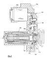
- An electromechanical actuator 1 of the invention is intended to selectively apply a braking force on friction elements of an aircraft brake, here a stack of disks 2.
- This actuator 1 comprises a body 3 fixed to a brake actuator carrier by means of fastening not shown.
- an electric motor 4 Inside this body are arranged an electric motor 4, a gearbox 5 with three stages transmitting the rotational movement of a motor shaft to a nut 6 rotatably mounted in the body 3 and which cooperates with a screw 7 forming a pusher .
- the pusher 7 is threaded on a first length 8 to cooperate via a screw / nut connection with the nut 6.
- the pusher further comprises a cylindrical running portion 9 of X axis bearing at its end a pad 10 .
- An anti-rotation device here comprises a splined central finger 12 cooperating with the internal grooves of the pusher 7 preventing any rotation of the pusher 7 about the X axis.
- the electromechanical actuator of the invention further comprises two double-lip scraper seals 13, 14 which here extend in series between the body 3 and the pusher 7, close to the opening 11 made in the body 3.
- two scraper seals are housed in body gorges.
- these two seals 13, 14 are fixed and are arranged to scrape the pusher during its sliding.
- Each wiper seal 13, 14 comprises a wiper lip 15, 16 and a sealing lip 17, 18 held in pressure by an O-ring 19, 20.
- the sealing lip 17 of the seal 13 closest to the opening 11 is oriented so as to seal the outside of the actuator 1 towards the inside.
- the sealing lip 18 of the other gasket 14 is, in turn, oriented so as to seal from the inside to the outside. This arrangement of the seals makes it possible to prevent any entry of particles (dust, water, etc.) into the actuator, and any exit of lubricating fluid.
- the electromechanical actuator of the invention 101 comprises a body 103 in which are arranged an electric motor 104, a gearbox 105, a nut 106 and a pusher 107.
- the motor 104, the gearbox 105 and the pusher 107 are strictly identical to those of the first embodiment.
- the body 103 is identical to that of the first embodiment, with the difference that the arrangement of the joints is different.
- the body 103 includes a first double lip scraper 113, which extends between the body 103 and the pusher 107, in a similar arrangement to that of the seal closest to the opening in the first embodiment.
- the nut 106 is here provided with a cage 140 surrounding the pusher 107 near an opening 111 formed in the body 103.
- the cage 140 has a groove in which is housed the second double-lip scraper seal 114, which extends between the cage 140 of the nut and the pusher 107.
- the first seal 113 is fixed while the second seal 114 rotates with the nut.
- the relative arrangement of the sealing and scraping lips of the two seals 113, 114 is similar to that of the first embodiment.
- an additional dynamic seal 141 here formed of a sealing member 142 provided with contact lips and held in pressure by an O-ring 143 extends between the body 103 and the nut 106.
- This additional dynamic seal 141 housed in a groove of the body, is therefore fixed and provides sealing between the fixed body and the rotary nut.
- seals with a scraping lip and a sealing lip have been used, it is well it is certainly possible to use seals that do not have a scraper lip, or seals with a different number of lips (and in particular seals with a single lip).
Landscapes
- Engineering & Computer Science (AREA)
- General Engineering & Computer Science (AREA)
- Mechanical Engineering (AREA)
- Sealing Devices (AREA)
Abstract
Description
- L'invention concerne un actionneur électromécanique d'un frein d'une roue d'aéronef comportant deux joints à lèvre montés pour assurer l'étanchéité de l'actionneur.
- Un système de freinage dit « électrique », destiné à freiner des roues freinées d'un aéronef, comporte de nombreux équipements électriques, électromécaniques et mécaniques, parmi lesquels certains sont soit très complexes techniquement, soit installés dans des environnements particulièrement sévères.
- Les équipements électriques comprennent, selon l'architecture du système, des organes de puissances pour mettre en forme et transmettre vers les freins l'énergie électrique nécessaire à leur activation, et des organes de commande pour commander le freinage et assurer des fonctions telles qu'une fonction d'anti-patinage. Ces équipements électriques peuvent comprendre de très nombreux composants électroniques, et ont une fiabilité théorique relativement faible.
- Chaque roue freinée est munie d'un frein comportant une pile de disques, généralement fabriqués en carbone et empilés autour d'un tube de torsion, et des actionneurs électromécaniques portés par un porte-actionneurs et commandés pour appliquer un effort de freinage sur la pile de disques en vue d'exercer sur la roue un couple de freinage tendant à ralentir l'aéronef. Les actionneurs électromécaniques sont alimentés électriquement par les organes de puissance et commandés par les organes de commande. Ils comportent un moteur électrique adapté à déplacer un poussoir en regard de la pile de disques.
- L'environnement du frein est particulièrement rigoureux. Lors d'un freinage, la température des disques peut passer brusquement d'une température très basse
- (parfois inférieure à -50 degrés Celsius) à une température très haute (parfois supérieure à 1000 degrés Celsius) et les contraintes mécaniques (vibrations, chocs) sont particulièrement sévères. Le frein est soumis en outre à de nombreuses projections: détritus de la piste, sable et poussières, eau pressurisée lors d'un lavage, grêle, etc. Cet environnement peut avoir un impact sur la fiabilité des équipements composant le frein.
- L'invention a pour objet d'améliorer la fiabilité d'un système de freinage électrique.
- En vue de la réalisation de ce but, on propose un actionneur électromécanique de freinage destiné à appliquer sélectivement un effort de freinage sur des éléments de friction d'un frein d'une roue d'aéronef, l'actionneur électromécanique comportant un corps dans lequel un poussoir est monté pour coulisser longitudinalement sous l'action d'un moteur électrique en saillant du corps au travers d'une ouverture pratiquée dans celui-ci. Selon l'invention, l'actionneur comporte deux joints à lèvre qui coopèrent avec le poussoir et qui sont disposés de sorte que l'un des joints à lèvre s'oppose à l'entrée de particules dans l'intérieur du corps par l'ouverture pratiquée dans le corps, et que l'autre des joints à lèvre s'oppose à la sortie par ladite ouverture de fluide contenu dans l'intérieur du corps.
- Cette disposition des joints à lèvre permet d'augmenter de manière importante la fiabilité de l'actionneur électromécanique, et donc celle d'un système de freinage dans lequel il est intégré.
- En effet, les joints à lèvre empêchent, d'une part, toute entrée de particules dans l'actionneur par l'ouverture du corps, et notamment des particules de carbone provenant des éléments de friction du frein, de sable, d'eau, de poussière, et d'autre part, toute fuite de fluide lubrifiant de composants internes de l'actionneur. L'intérieur de l'actionneur est donc préservé, et la fiabilité de l'actionneur est améliorée.
- L'invention sera mieux comprise à la lumière de la description qui suit en référence aux figures des dessins annexés parmi lesquelles :
- la
figure 1 est une vue en coupe d'un actionneur électromécanique de l'invention selon un premier mode de réalisation, - la
figure 2 est une vue en coupe d'un actionneur électromécanique de l'invention selon un second mode de réalisation. - Un actionneur électromécanique 1 de l'invention, selon un premier mode de réalisation visible à la
figure 1 , est destiné à appliquer sélectivement un effort de freinage sur des éléments de friction d'un frein d'aéronef, ici une pile de disques 2. Cet actionneur 1 comporte un corps 3 fixé à un porte-actionneurs du frein grâce à des moyens de fixation non représentés. - A l'intérieur de ce corps sont agencés un moteur électrique 4, un réducteur 5 à trois étages transmettant le mouvement de rotation d'un arbre du moteur à un écrou 6 monté tournant dans le corps 3 et qui coopère avec une vis 7 formant poussoir. Le poussoir 7 est fileté sur une première longueur 8 pour coopérer par l'intermédiaire d'une liaison vis/écrou avec l'écrou 6. Le poussoir comporte par ailleurs une partie courante cylindrique 9 d'axe X portant à son extrémité un patin 10.
- Ainsi, sous l'action du moteur électrique 4, le poussoir 7 coulisse selon l'axe X en saillant du corps 3 au travers d'une ouverture 11 pratiquée dans le corps 3 de sorte que le patin 10 vienne au contact de la pile de disques 2. Un dispositif d'anti-rotation comprend ici un doigt central cannelé 12 coopérant avec des cannelures internes du poussoir 7 empêchant toute rotation du poussoir 7 autour de l'axe X.
- Tout ceci est bien connu et n'est rappelé que pour donner le contexte de l'invention.
- L'actionneur électromécanique de l'invention comporte en outre deux joints racleur 13, 14 à double lèvre qui s'étendent ici en série entre le corps 3 et le poussoir 7, à proximité de l'ouverture 11 pratiquée dans le corps 3. Les deux joints racleurs sont logés dans des gorges du corps. Ainsi, ces deux joints 13, 14 sont fixes et sont disposés pour racler le poussoir lors de ses coulissements.
- Chaque joint racleur 13, 14 comporte une lèvre racleuse 15, 16 et une lèvre d'étanchéité 17, 18 maintenue en pression par un joint torique 19, 20. La lèvre d'étanchéité 17 du joint 13 le plus proche de l'ouverture 11 est orientée de manière à assurer une étanchéité de l'extérieur de l'actionneur 1 vers l'intérieur. La lèvre d'étanchéité 18 de l'autre joint 14 est, quant à elle, orientée de manière à assurer une étanchéité de l'intérieur vers l'extérieur. Cet agencement des joints permet d'empêcher toute entrée de particules (poussières, eau, etc.) dans l'actionneur, et toute sortie de fluide lubrifiant.
- Dans un deuxième mode de réalisation, visible à la
figure 2 , l'actionneur électromécanique de l'invention 101 comporte un corps 103 dans lequel sont agencés un moteur électrique 104, un réducteur 105, un écrou 106 et un poussoir 107. Le moteur 104, le réducteur 105 et le poussoir 107 sont strictement identiques à ceux du premier mode de réalisation. Le corps 103 est identique à celui du premier mode de réalisation, à la différence près que l'agencement des joints est différents. - Le corps 103 comporte un premier joint racleur 113 à double lèvre, qui s'étend entre le corps 103 et le poussoir 107, dans un agencement similaire à celui du joint le plus proche de l'ouverture dans le premier mode de réalisation. L'écrou 106 est ici muni d'une cage 140 entourant le poussoir 107 à proximité d'une ouverture 111 pratiquée dans le corps 103. La cage 140 comporte une gorge dans laquelle est logé le deuxième joint racleur 114 à double lèvre, qui s'étend entre la cage 140 de l'écrou et le poussoir 107. Le premier joint 113 est donc fixe tandis que le deuxième joint 114 tourne avec l'écrou. L'agencement relatif des lèvres d'étanchéité et racleuses des deux joints 113, 114 est similaire à celui du premier mode de réalisation. Cet agencement des joints permet d'empêcher toute entrée de particules dans le corps 103 de l'actionneur 101, et toute sortie de fluide par l'espace s'étendant entre l'écrou 106 et le poussoir 107. Pour empêcher toute sortie de fluide par l'espace s'étendant entre le corps 103 et l'écrou 106, un joint d'étanchéité dynamique additionnel 141, ici formé d'un élément d'étanchéité 142 muni de lèvres de contact et maintenu en pression par un joint torique 143, s'étend entre le corps 103 et l'écrou 106. Ce joint d'étanchéité dynamique additionnel 141, logé dans une gorge du corps, est donc fixe et réalise l'étanchéité entre le corps fixe et l'écrou rotatif.
- L'invention n'est pas limitée aux modes de réalisation particuliers qui viennent d'être décrit, mais, bien au contraire, englobe toute variante entrant dans le cadre de l'invention tel que défini par les revendications.
- Bien que l'on ait utilisé des joints munis d'une lèvre racleuse et d'une lèvre d'étanchéité, il est bien sûr possible d'utiliser des joints ne comportant pas de lèvre racleuse, ou bien des joints comportant un nombre de lèvres différent (et notamment des joints comportant une unique lèvre).
- Bien que l'on ait choisi d'illustrer l'invention en prévoyant que le joint le plus proche de l'ouverture empêche l'entrée de particules et l'autre la sortie de fluide, il est bien sûr possible d'inverser cette configuration.
- Il est aussi possible de choisir un joint dynamique différent pour le troisième joint du deuxième mode de réalisation (simple joint torique, joint à lèvres, à chicane, etc.).
Claims (5)
- Actionneur électromécanique destiné à appliquer sélectivement un effort de freinage sur des éléments de friction (2) d'un frein d'une roue d'aéronef, l'actionneur électromécanique comportant un corps (3 ; 103) dans lequel un poussoir (7 ; 107) est monté pour coulisser longitudinalement sous l'action d'un moteur électrique (4 ; 104) en saillant du corps au travers d'une ouverture (11 ; 111) pratiquée dans celui-ci, caractérisé en ce que l'actionneur comporte deux joints à lèvre (13, 14 ; 113, 114) qui coopèrent avec le poussoir et qui sont disposés de sorte que l'un des joints à lèvre (13 ; 113) s'oppose à l'entrée de particules dans l'intérieur du corps par l'ouverture pratiquée dans le corps, et que l'autre des joints à lèvre (14 ; 114) s'oppose à la sortie par ladite ouverture de fluide contenu dans l'intérieur du corps.
- Actionneur électromécanique selon la revendication 1, dans lequel les deux joints à lèvre (13, 14 ; 113, 114) s'étendent entre le corps et le poussoir.
- Actionneur électromécanique selon la revendication 1, dans lequel un joint à lèvre (113) s'étend entre le corps et le poussoir, tandis que l'autre joint à lèvre (114) s'étend entre le poussoir (107) et un élément de transmission (106) entraîné par le moteur électrique et coopérant avec le poussoir par une liaison vis/écrou.
- Actionneur électromécanique selon la revendication 1, dans lequel au moins un des joints à lèvre comporte une lèvre racleuse.
- Actionneur électromécanique selon la revendication 1, comportant en outre un joint supplémentaire (141) s'étendant entre le corps (103) et l'élément de transmission (106).
Applications Claiming Priority (1)
| Application Number | Priority Date | Filing Date | Title |
|---|---|---|---|
| FR1255587A FR2992038B1 (fr) | 2012-06-14 | 2012-06-14 | Actionneur electromecanique |
Publications (2)
| Publication Number | Publication Date |
|---|---|
| EP2674639A1 true EP2674639A1 (fr) | 2013-12-18 |
| EP2674639B1 EP2674639B1 (fr) | 2020-09-09 |
Family
ID=48463894
Family Applications (1)
| Application Number | Title | Priority Date | Filing Date |
|---|---|---|---|
| EP13169421.8A Active EP2674639B1 (fr) | 2012-06-14 | 2013-05-28 | Actionneur électromécanique |
Country Status (2)
| Country | Link |
|---|---|
| EP (1) | EP2674639B1 (fr) |
| FR (1) | FR2992038B1 (fr) |
Citations (7)
| Publication number | Priority date | Publication date | Assignee | Title |
|---|---|---|---|---|
| FR2377558A1 (fr) * | 1977-01-17 | 1978-08-11 | Citroen Sa | Frein a disque |
| US4476772A (en) * | 1982-11-04 | 1984-10-16 | Corbett Elevator Manufacturing Co., Inc. | Caging seal for hydraulic elevator or the like |
| US6290235B1 (en) * | 1997-07-02 | 2001-09-18 | Parker-Hannifin Corporation | Sealing system for a reciprocating shaft |
| WO2002057649A1 (fr) * | 2001-01-18 | 2002-07-25 | Sagem S.A. | Actionneur electromecanique de frein a disques multiples pour moyyen de transport, notamment pour avion |
| US6607059B1 (en) * | 1998-11-17 | 2003-08-19 | Skf Engineering And Research Centre B.V. | Screw actuator comprising a multi-purpose sleeve, and brake calliper |
| US20080135349A1 (en) * | 2004-06-04 | 2008-06-12 | Goodrich Corporation | Electric Brake for Aircraft |
| EP2103830A1 (fr) * | 2008-03-19 | 2009-09-23 | Umbra Cuscinetti S.p.A. | Actionneur linéaires électromécanique |
-
2012
- 2012-06-14 FR FR1255587A patent/FR2992038B1/fr active Active
-
2013
- 2013-05-28 EP EP13169421.8A patent/EP2674639B1/fr active Active
Patent Citations (7)
| Publication number | Priority date | Publication date | Assignee | Title |
|---|---|---|---|---|
| FR2377558A1 (fr) * | 1977-01-17 | 1978-08-11 | Citroen Sa | Frein a disque |
| US4476772A (en) * | 1982-11-04 | 1984-10-16 | Corbett Elevator Manufacturing Co., Inc. | Caging seal for hydraulic elevator or the like |
| US6290235B1 (en) * | 1997-07-02 | 2001-09-18 | Parker-Hannifin Corporation | Sealing system for a reciprocating shaft |
| US6607059B1 (en) * | 1998-11-17 | 2003-08-19 | Skf Engineering And Research Centre B.V. | Screw actuator comprising a multi-purpose sleeve, and brake calliper |
| WO2002057649A1 (fr) * | 2001-01-18 | 2002-07-25 | Sagem S.A. | Actionneur electromecanique de frein a disques multiples pour moyyen de transport, notamment pour avion |
| US20080135349A1 (en) * | 2004-06-04 | 2008-06-12 | Goodrich Corporation | Electric Brake for Aircraft |
| EP2103830A1 (fr) * | 2008-03-19 | 2009-09-23 | Umbra Cuscinetti S.p.A. | Actionneur linéaires électromécanique |
Also Published As
| Publication number | Publication date |
|---|---|
| FR2992038A1 (fr) | 2013-12-20 |
| EP2674639B1 (fr) | 2020-09-09 |
| FR2992038B1 (fr) | 2014-07-04 |
Similar Documents
| Publication | Publication Date | Title |
|---|---|---|
| EP3175146B1 (fr) | Réducteur de couple | |
| FR3016014A1 (fr) | Actionneur avec systeme vis-ecrou irreversible, frein a tambour et dispositif de freinage ainsi equipes | |
| EP1352181A1 (fr) | Actionneur electromecanique de frein a disques multiples pour moyen de transport, notamment pour avion | |
| EP3175136B1 (fr) | Actionneur de freinage pour véhicule | |
| FR3022526A1 (fr) | Actionneur electromecanique a limiteur de couple magnetique | |
| EP3087285B1 (fr) | Frein à disque perfectionné comportant un frein de stationnement à actionnement hydraulique et un groupe de rattrapage d'usure | |
| EP0143709B1 (fr) | Système de freinage comprenant au moins un disque de frein coulissant | |
| EP2674639B1 (fr) | Actionneur électromécanique | |
| EP3237244B1 (fr) | Moteur hydraulique couple | |
| FR2864594A1 (fr) | Frein de vehicule electromagnetique autoamplification | |
| WO2019149540A1 (fr) | Actionneur d'embrayage | |
| WO2016202599A1 (fr) | Dispositif d'actionnement de systeme de freinage | |
| EP2683580B1 (fr) | Dispositif d'essuie-glace à vis à billes et fourchette | |
| FR3023656A1 (fr) | Actionneur electromecanique a dispositif de freinage double fonction | |
| EP3087288B1 (fr) | Frein à disque à commande hydraulique comportant un frein de stationnement à actionnement hydraulique | |
| EP3746670B1 (fr) | Actionneur d'embrayage | |
| FR2764030A1 (fr) | Dispositif d'actionnement d'une boite a vitesses automatisee | |
| EP3087289B1 (fr) | Frein à disque perfectionné comportant un frein de stationnement à actionnement hydraulique | |
| FR3073495B1 (fr) | Atterrisseur d'aeronef | |
| FR3129901A1 (fr) | Système de freinage à actionnement équilibré | |
| FR2989060A1 (fr) | Systeme anti-retour et actionneur de commande de vol comprenant un tel systeme | |
| FR2881798A1 (fr) | Dispositif de demarrage d'un moteur thermique | |
| FR2998633A1 (fr) | Dispositif electro-hydraulique d’actionnement d’embrayage pour boite de vitesses automatisee | |
| FR2993949A1 (fr) | Dispositif electro-hydraulique de commande d'embrayage pour boite de vitesses automatisee | |
| FR3105327A1 (fr) | Dispositif de freinage à usure réduite |
Legal Events
| Date | Code | Title | Description |
|---|---|---|---|
| PUAI | Public reference made under article 153(3) epc to a published international application that has entered the european phase |
Free format text: ORIGINAL CODE: 0009012 |
|
| AK | Designated contracting states |
Kind code of ref document: A1 Designated state(s): AL AT BE BG CH CY CZ DE DK EE ES FI FR GB GR HR HU IE IS IT LI LT LU LV MC MK MT NL NO PL PT RO RS SE SI SK SM TR |
|
| AX | Request for extension of the european patent |
Extension state: BA ME |
|
| 17P | Request for examination filed |
Effective date: 20140616 |
|
| RBV | Designated contracting states (corrected) |
Designated state(s): AL AT BE BG CH CY CZ DE DK EE ES FI FR GB GR HR HU IE IS IT LI LT LU LV MC MK MT NL NO PL PT RO RS SE SI SK SM TR |
|
| RAP1 | Party data changed (applicant data changed or rights of an application transferred) |
Owner name: SAFRAN LANDING SYSTEMS |
|
| RAP1 | Party data changed (applicant data changed or rights of an application transferred) |
Owner name: SAFRAN LANDING SYSTEMS |
|
| STAA | Information on the status of an ep patent application or granted ep patent |
Free format text: STATUS: EXAMINATION IS IN PROGRESS |
|
| 17Q | First examination report despatched |
Effective date: 20180905 |
|
| GRAP | Despatch of communication of intention to grant a patent |
Free format text: ORIGINAL CODE: EPIDOSNIGR1 |
|
| STAA | Information on the status of an ep patent application or granted ep patent |
Free format text: STATUS: GRANT OF PATENT IS INTENDED |
|
| INTG | Intention to grant announced |
Effective date: 20190404 |
|
| RIN1 | Information on inventor provided before grant (corrected) |
Inventor name: CHICOT, PHILIPPE |
|
| GRAJ | Information related to disapproval of communication of intention to grant by the applicant or resumption of examination proceedings by the epo deleted |
Free format text: ORIGINAL CODE: EPIDOSDIGR1 |
|
| GRAP | Despatch of communication of intention to grant a patent |
Free format text: ORIGINAL CODE: EPIDOSNIGR1 |
|
| INTG | Intention to grant announced |
Effective date: 20191011 |
|
| INTG | Intention to grant announced |
Effective date: 20191011 |
|
| GRAJ | Information related to disapproval of communication of intention to grant by the applicant or resumption of examination proceedings by the epo deleted |
Free format text: ORIGINAL CODE: EPIDOSDIGR1 |
|
| STAA | Information on the status of an ep patent application or granted ep patent |
Free format text: STATUS: EXAMINATION IS IN PROGRESS |
|
| INTC | Intention to grant announced (deleted) | ||
| GRAP | Despatch of communication of intention to grant a patent |
Free format text: ORIGINAL CODE: EPIDOSNIGR1 |
|
| STAA | Information on the status of an ep patent application or granted ep patent |
Free format text: STATUS: GRANT OF PATENT IS INTENDED |
|
| INTG | Intention to grant announced |
Effective date: 20200401 |
|
| GRAS | Grant fee paid |
Free format text: ORIGINAL CODE: EPIDOSNIGR3 |
|
| GRAA | (expected) grant |
Free format text: ORIGINAL CODE: 0009210 |
|
| STAA | Information on the status of an ep patent application or granted ep patent |
Free format text: STATUS: THE PATENT HAS BEEN GRANTED |
|
| AK | Designated contracting states |
Kind code of ref document: B1 Designated state(s): AL AT BE BG CH CY CZ DE DK EE ES FI FR GB GR HR HU IE IS IT LI LT LU LV MC MK MT NL NO PL PT RO RS SE SI SK SM TR |
|
| REG | Reference to a national code |
Ref country code: GB Ref legal event code: FG4D Free format text: NOT ENGLISH |
|
| REG | Reference to a national code |
Ref country code: AT Ref legal event code: REF Ref document number: 1311961 Country of ref document: AT Kind code of ref document: T Effective date: 20200915 Ref country code: CH Ref legal event code: EP |
|
| REG | Reference to a national code |
Ref country code: DE Ref legal event code: R096 Ref document number: 602013072313 Country of ref document: DE |
|
| REG | Reference to a national code |
Ref country code: IE Ref legal event code: FG4D Free format text: LANGUAGE OF EP DOCUMENT: FRENCH |
|
| REG | Reference to a national code |
Ref country code: LT Ref legal event code: MG4D |
|
| PG25 | Lapsed in a contracting state [announced via postgrant information from national office to epo] |
Ref country code: SE Free format text: LAPSE BECAUSE OF FAILURE TO SUBMIT A TRANSLATION OF THE DESCRIPTION OR TO PAY THE FEE WITHIN THE PRESCRIBED TIME-LIMIT Effective date: 20200909 Ref country code: BG Free format text: LAPSE BECAUSE OF FAILURE TO SUBMIT A TRANSLATION OF THE DESCRIPTION OR TO PAY THE FEE WITHIN THE PRESCRIBED TIME-LIMIT Effective date: 20201209 Ref country code: NO Free format text: LAPSE BECAUSE OF FAILURE TO SUBMIT A TRANSLATION OF THE DESCRIPTION OR TO PAY THE FEE WITHIN THE PRESCRIBED TIME-LIMIT Effective date: 20201209 Ref country code: FI Free format text: LAPSE BECAUSE OF FAILURE TO SUBMIT A TRANSLATION OF THE DESCRIPTION OR TO PAY THE FEE WITHIN THE PRESCRIBED TIME-LIMIT Effective date: 20200909 Ref country code: GR Free format text: LAPSE BECAUSE OF FAILURE TO SUBMIT A TRANSLATION OF THE DESCRIPTION OR TO PAY THE FEE WITHIN THE PRESCRIBED TIME-LIMIT Effective date: 20201210 Ref country code: HR Free format text: LAPSE BECAUSE OF FAILURE TO SUBMIT A TRANSLATION OF THE DESCRIPTION OR TO PAY THE FEE WITHIN THE PRESCRIBED TIME-LIMIT Effective date: 20200909 Ref country code: LT Free format text: LAPSE BECAUSE OF FAILURE TO SUBMIT A TRANSLATION OF THE DESCRIPTION OR TO PAY THE FEE WITHIN THE PRESCRIBED TIME-LIMIT Effective date: 20200909 |
|
| REG | Reference to a national code |
Ref country code: AT Ref legal event code: MK05 Ref document number: 1311961 Country of ref document: AT Kind code of ref document: T Effective date: 20200909 |
|
| REG | Reference to a national code |
Ref country code: NL Ref legal event code: MP Effective date: 20200909 |
|
| PG25 | Lapsed in a contracting state [announced via postgrant information from national office to epo] |
Ref country code: LV Free format text: LAPSE BECAUSE OF FAILURE TO SUBMIT A TRANSLATION OF THE DESCRIPTION OR TO PAY THE FEE WITHIN THE PRESCRIBED TIME-LIMIT Effective date: 20200909 Ref country code: PL Free format text: LAPSE BECAUSE OF FAILURE TO SUBMIT A TRANSLATION OF THE DESCRIPTION OR TO PAY THE FEE WITHIN THE PRESCRIBED TIME-LIMIT Effective date: 20200909 Ref country code: RS Free format text: LAPSE BECAUSE OF FAILURE TO SUBMIT A TRANSLATION OF THE DESCRIPTION OR TO PAY THE FEE WITHIN THE PRESCRIBED TIME-LIMIT Effective date: 20200909 |
|
| PG25 | Lapsed in a contracting state [announced via postgrant information from national office to epo] |
Ref country code: EE Free format text: LAPSE BECAUSE OF FAILURE TO SUBMIT A TRANSLATION OF THE DESCRIPTION OR TO PAY THE FEE WITHIN THE PRESCRIBED TIME-LIMIT Effective date: 20200909 Ref country code: CZ Free format text: LAPSE BECAUSE OF FAILURE TO SUBMIT A TRANSLATION OF THE DESCRIPTION OR TO PAY THE FEE WITHIN THE PRESCRIBED TIME-LIMIT Effective date: 20200909 Ref country code: RO Free format text: LAPSE BECAUSE OF FAILURE TO SUBMIT A TRANSLATION OF THE DESCRIPTION OR TO PAY THE FEE WITHIN THE PRESCRIBED TIME-LIMIT Effective date: 20200909 Ref country code: SM Free format text: LAPSE BECAUSE OF FAILURE TO SUBMIT A TRANSLATION OF THE DESCRIPTION OR TO PAY THE FEE WITHIN THE PRESCRIBED TIME-LIMIT Effective date: 20200909 Ref country code: PT Free format text: LAPSE BECAUSE OF FAILURE TO SUBMIT A TRANSLATION OF THE DESCRIPTION OR TO PAY THE FEE WITHIN THE PRESCRIBED TIME-LIMIT Effective date: 20210111 Ref country code: NL Free format text: LAPSE BECAUSE OF FAILURE TO SUBMIT A TRANSLATION OF THE DESCRIPTION OR TO PAY THE FEE WITHIN THE PRESCRIBED TIME-LIMIT Effective date: 20200909 |
|
| PG25 | Lapsed in a contracting state [announced via postgrant information from national office to epo] |
Ref country code: AL Free format text: LAPSE BECAUSE OF FAILURE TO SUBMIT A TRANSLATION OF THE DESCRIPTION OR TO PAY THE FEE WITHIN THE PRESCRIBED TIME-LIMIT Effective date: 20200909 Ref country code: AT Free format text: LAPSE BECAUSE OF FAILURE TO SUBMIT A TRANSLATION OF THE DESCRIPTION OR TO PAY THE FEE WITHIN THE PRESCRIBED TIME-LIMIT Effective date: 20200909 Ref country code: ES Free format text: LAPSE BECAUSE OF FAILURE TO SUBMIT A TRANSLATION OF THE DESCRIPTION OR TO PAY THE FEE WITHIN THE PRESCRIBED TIME-LIMIT Effective date: 20200909 Ref country code: IS Free format text: LAPSE BECAUSE OF FAILURE TO SUBMIT A TRANSLATION OF THE DESCRIPTION OR TO PAY THE FEE WITHIN THE PRESCRIBED TIME-LIMIT Effective date: 20210109 |
|
| REG | Reference to a national code |
Ref country code: DE Ref legal event code: R097 Ref document number: 602013072313 Country of ref document: DE |
|
| PG25 | Lapsed in a contracting state [announced via postgrant information from national office to epo] |
Ref country code: SK Free format text: LAPSE BECAUSE OF FAILURE TO SUBMIT A TRANSLATION OF THE DESCRIPTION OR TO PAY THE FEE WITHIN THE PRESCRIBED TIME-LIMIT Effective date: 20200909 |
|
| PLBE | No opposition filed within time limit |
Free format text: ORIGINAL CODE: 0009261 |
|
| STAA | Information on the status of an ep patent application or granted ep patent |
Free format text: STATUS: NO OPPOSITION FILED WITHIN TIME LIMIT |
|
| 26N | No opposition filed |
Effective date: 20210610 |
|
| PG25 | Lapsed in a contracting state [announced via postgrant information from national office to epo] |
Ref country code: SI Free format text: LAPSE BECAUSE OF FAILURE TO SUBMIT A TRANSLATION OF THE DESCRIPTION OR TO PAY THE FEE WITHIN THE PRESCRIBED TIME-LIMIT Effective date: 20200909 Ref country code: DK Free format text: LAPSE BECAUSE OF FAILURE TO SUBMIT A TRANSLATION OF THE DESCRIPTION OR TO PAY THE FEE WITHIN THE PRESCRIBED TIME-LIMIT Effective date: 20200909 |
|
| REG | Reference to a national code |
Ref country code: CH Ref legal event code: PL |
|
| PG25 | Lapsed in a contracting state [announced via postgrant information from national office to epo] |
Ref country code: CH Free format text: LAPSE BECAUSE OF NON-PAYMENT OF DUE FEES Effective date: 20210531 Ref country code: LI Free format text: LAPSE BECAUSE OF NON-PAYMENT OF DUE FEES Effective date: 20210531 Ref country code: MC Free format text: LAPSE BECAUSE OF FAILURE TO SUBMIT A TRANSLATION OF THE DESCRIPTION OR TO PAY THE FEE WITHIN THE PRESCRIBED TIME-LIMIT Effective date: 20200909 Ref country code: LU Free format text: LAPSE BECAUSE OF NON-PAYMENT OF DUE FEES Effective date: 20210528 |
|
| REG | Reference to a national code |
Ref country code: BE Ref legal event code: MM Effective date: 20210531 |
|
| PG25 | Lapsed in a contracting state [announced via postgrant information from national office to epo] |
Ref country code: IE Free format text: LAPSE BECAUSE OF NON-PAYMENT OF DUE FEES Effective date: 20210528 |
|
| PG25 | Lapsed in a contracting state [announced via postgrant information from national office to epo] |
Ref country code: BE Free format text: LAPSE BECAUSE OF NON-PAYMENT OF DUE FEES Effective date: 20210531 |
|
| PG25 | Lapsed in a contracting state [announced via postgrant information from national office to epo] |
Ref country code: HU Free format text: LAPSE BECAUSE OF FAILURE TO SUBMIT A TRANSLATION OF THE DESCRIPTION OR TO PAY THE FEE WITHIN THE PRESCRIBED TIME-LIMIT; INVALID AB INITIO Effective date: 20130528 |
|
| PG25 | Lapsed in a contracting state [announced via postgrant information from national office to epo] |
Ref country code: CY Free format text: LAPSE BECAUSE OF FAILURE TO SUBMIT A TRANSLATION OF THE DESCRIPTION OR TO PAY THE FEE WITHIN THE PRESCRIBED TIME-LIMIT Effective date: 20200909 |
|
| PG25 | Lapsed in a contracting state [announced via postgrant information from national office to epo] |
Ref country code: MK Free format text: LAPSE BECAUSE OF FAILURE TO SUBMIT A TRANSLATION OF THE DESCRIPTION OR TO PAY THE FEE WITHIN THE PRESCRIBED TIME-LIMIT Effective date: 20200909 |
|
| PG25 | Lapsed in a contracting state [announced via postgrant information from national office to epo] |
Ref country code: MT Free format text: LAPSE BECAUSE OF FAILURE TO SUBMIT A TRANSLATION OF THE DESCRIPTION OR TO PAY THE FEE WITHIN THE PRESCRIBED TIME-LIMIT Effective date: 20200909 |
|
| PG25 | Lapsed in a contracting state [announced via postgrant information from national office to epo] |
Ref country code: TR Free format text: LAPSE BECAUSE OF FAILURE TO SUBMIT A TRANSLATION OF THE DESCRIPTION OR TO PAY THE FEE WITHIN THE PRESCRIBED TIME-LIMIT Effective date: 20200909 |
|
| PGFP | Annual fee paid to national office [announced via postgrant information from national office to epo] |
Ref country code: GB Payment date: 20260521 Year of fee payment: 14 |
|
| PGFP | Annual fee paid to national office [announced via postgrant information from national office to epo] |
Ref country code: IT Payment date: 20260529 Year of fee payment: 14 |
|
| PGFP | Annual fee paid to national office [announced via postgrant information from national office to epo] |
Ref country code: DE Payment date: 20260520 Year of fee payment: 14 |
|
| PGFP | Annual fee paid to national office [announced via postgrant information from national office to epo] |
Ref country code: FR Payment date: 20260522 Year of fee payment: 14 |