EP2674630B1 - Turbomachine alignment pin - Google Patents
Turbomachine alignment pin Download PDFInfo
- Publication number
- EP2674630B1 EP2674630B1 EP13171412.3A EP13171412A EP2674630B1 EP 2674630 B1 EP2674630 B1 EP 2674630B1 EP 13171412 A EP13171412 A EP 13171412A EP 2674630 B1 EP2674630 B1 EP 2674630B1
- Authority
- EP
- European Patent Office
- Prior art keywords
- expandable sleeve
- turbomachine
- alignment pin
- sleeve section
- slot
- Prior art date
- Legal status (The legal status is an assumption and is not a legal conclusion. Google has not performed a legal analysis and makes no representation as to the accuracy of the status listed.)
- Active
Links
Images


Classifications
-
- F—MECHANICAL ENGINEERING; LIGHTING; HEATING; WEAPONS; BLASTING
- F16—ENGINEERING ELEMENTS AND UNITS; GENERAL MEASURES FOR PRODUCING AND MAINTAINING EFFECTIVE FUNCTIONING OF MACHINES OR INSTALLATIONS; THERMAL INSULATION IN GENERAL
- F16B—DEVICES FOR FASTENING OR SECURING CONSTRUCTIONAL ELEMENTS OR MACHINE PARTS TOGETHER, e.g. NAILS, BOLTS, CIRCLIPS, CLAMPS, CLIPS OR WEDGES; JOINTS OR JOINTING
- F16B13/00—Dowels or other devices fastened in walls or the like by inserting them in holes made therein for that purpose
- F16B13/04—Dowels or other devices fastened in walls or the like by inserting them in holes made therein for that purpose with parts gripping in the hole or behind the reverse side of the wall after inserting from the front
- F16B13/08—Dowels or other devices fastened in walls or the like by inserting them in holes made therein for that purpose with parts gripping in the hole or behind the reverse side of the wall after inserting from the front with separate or non-separate gripping parts moved into their final position in relation to the body of the device without further manual operation
- F16B13/0858—Dowels or other devices fastened in walls or the like by inserting them in holes made therein for that purpose with parts gripping in the hole or behind the reverse side of the wall after inserting from the front with separate or non-separate gripping parts moved into their final position in relation to the body of the device without further manual operation with an expansible sleeve or dowel body driven against a tapered or spherical expander plug
-
- F—MECHANICAL ENGINEERING; LIGHTING; HEATING; WEAPONS; BLASTING
- F16—ENGINEERING ELEMENTS AND UNITS; GENERAL MEASURES FOR PRODUCING AND MAINTAINING EFFECTIVE FUNCTIONING OF MACHINES OR INSTALLATIONS; THERMAL INSULATION IN GENERAL
- F16B—DEVICES FOR FASTENING OR SECURING CONSTRUCTIONAL ELEMENTS OR MACHINE PARTS TOGETHER, e.g. NAILS, BOLTS, CIRCLIPS, CLAMPS, CLIPS OR WEDGES; JOINTS OR JOINTING
- F16B19/00—Bolts without screw-thread; Pins, including deformable elements; Rivets
- F16B19/02—Bolts or sleeves for positioning of machine parts, e.g. notched taper pins, fitting pins, sleeves, eccentric positioning rings
-
- F—MECHANICAL ENGINEERING; LIGHTING; HEATING; WEAPONS; BLASTING
- F05—INDEXING SCHEMES RELATING TO ENGINES OR PUMPS IN VARIOUS SUBCLASSES OF CLASSES F01-F04
- F05D—INDEXING SCHEME FOR ASPECTS RELATING TO NON-POSITIVE-DISPLACEMENT MACHINES OR ENGINES, GAS-TURBINES OR JET-PROPULSION PLANTS
- F05D2230/00—Manufacture
- F05D2230/60—Assembly methods
- F05D2230/64—Assembly methods using positioning or alignment devices for aligning or centring, e.g. pins
-
- F—MECHANICAL ENGINEERING; LIGHTING; HEATING; WEAPONS; BLASTING
- F16—ENGINEERING ELEMENTS AND UNITS; GENERAL MEASURES FOR PRODUCING AND MAINTAINING EFFECTIVE FUNCTIONING OF MACHINES OR INSTALLATIONS; THERMAL INSULATION IN GENERAL
- F16B—DEVICES FOR FASTENING OR SECURING CONSTRUCTIONAL ELEMENTS OR MACHINE PARTS TOGETHER, e.g. NAILS, BOLTS, CIRCLIPS, CLAMPS, CLIPS OR WEDGES; JOINTS OR JOINTING
- F16B13/00—Dowels or other devices fastened in walls or the like by inserting them in holes made therein for that purpose
- F16B13/04—Dowels or other devices fastened in walls or the like by inserting them in holes made therein for that purpose with parts gripping in the hole or behind the reverse side of the wall after inserting from the front
- F16B13/06—Dowels or other devices fastened in walls or the like by inserting them in holes made therein for that purpose with parts gripping in the hole or behind the reverse side of the wall after inserting from the front combined with expanding sleeve
- F16B13/063—Dowels or other devices fastened in walls or the like by inserting them in holes made therein for that purpose with parts gripping in the hole or behind the reverse side of the wall after inserting from the front combined with expanding sleeve by the use of an expander
- F16B13/065—Dowels or other devices fastened in walls or the like by inserting them in holes made therein for that purpose with parts gripping in the hole or behind the reverse side of the wall after inserting from the front combined with expanding sleeve by the use of an expander fastened by extracting the screw, nail or the like
Definitions
- turbomachines More particularly, aspects of the invention include alignment mechanisms for a turbomachine stage, such as a stage in a steam turbine.
- Steam turbine designs include static nozzle assemblies that direct the flow of a working fluid such as steam into rotating buckets that are connected to a rotor.
- the nozzle (airfoil) construction is typically called a "diaphragm" or “nozzle assembly” stage.
- Turbine diaphragms are assembled in two halves around the rotor, creating a horizontal joint between these two halves.
- Diaphragm centering pins are used to position the diaphragms in the transverse direction during installation. These centering pins are also designed to take the torque load generated by the diaphragm.
- the centering pin is traditionally installed in an area of the diaphragm assembly with a small interference.
- the centering pin is traditionally cooled (e.g., frozen) to a point in which it contracts to fit in this area of small clearance. This often requires the use of dry ice or another severe cooling mechanism during installation, e.g., in the field. However, the unavailability and relatively high cost of these severe cooling mechanisms can be undesirable. Additionally, freezing and thawing of the centering pin can cause mis-alignment of the turbine diaphragm.
- An alignment pin for a steam turbine is known from JP S61 173825 U .
- the invention relates to an alignment pin for a turbomachine according to claim 1, to an alignment apparatus for a turbomachine according to claim 6 and to a turbomachine according to claim 12.
- the alignment pin includes a hollowed head section for engaging a diaphragm slot in the turbomachine.
- the alignment pin further includes an expandable sleeve section connected with the hollowed head, the expandable sleeve section is sized to engage a casing slot in the turbomachine.
- a first aspect of the invention includes an alignment pin for a turbomachine, the alignment pin including: a hollowed head section for engaging a diaphragm slot in the turbomachine; and an expandable sleeve section connected with the hollowed head, the expandable sleeve section is sized to engage a casing slot in the turbomachine.
- the expandable sleeve section includes an inner aperture for receiving an expansion member; the hollowed head section includes a lip for engaging a surface of a casing wall in the turbomachine.
- a second aspect of the invention includes an alignment apparatus for a turbomachine, the alignment apparatus including: an alignment pin according to the first aspect; and an expansion member within a portion of the inner aperture, the expansion member is provided for modifying an outer diameter of the expandable sleeve member within the casing slot.
- a third aspect of the invention includes a turbomachine having: a turbine diaphragm segment; a turbine casing segment substantially containing the turbine diaphragm segment; and an alignment pin according to the first aspect for aligning the turbine diaphragm segment with the turbine casing segment.
- aspects of the invention include alignment mechanisms for a turbomachine stage, such as a stage in a steam turbine.
- the centering pin in a conventional turbomachine is traditionally installed in an area of the diaphragm assembly with a small clearance.
- the centering pin is traditionally cooled (e.g., frozen) to a point in which it contracts to fit in this area of small clearance.
- This often requires the use of dry ice or another severe cooling mechanism during installation, e.g., in the field.
- the unavailability and relatively high cost of these severe cooling mechanisms can be undesirable.
- the centering pin is installed with a small degree (e.g., 0.0005- 0.002 inches, or 0.0127-0.0508 millimeters) interference fit in a casing slot.
- a small degree e.g., 0.0005- 0.002 inches, or 0.0127-0.0508 millimeters
- the centering pin is cooled (e.g., until frozen) to a temperature below zero degrees Fahrenheit (F), e.g., as cold as -140 degrees F.
- F zero degrees Fahrenheit
- various embodiments of the invention include a centering pin apparatus for a turbomachine which does not require cooling to insert into the diaphragm slot.
- the centering pin apparatus includes a sleeve having an internal aperture, such as a threaded internal aperture, extending at least partially therethrough.
- the internal aperture of the sleeve is designed to receive an expansion member for expanding a portion of the sleeve to fill the diaphragm slot.
- sleeves and “retainer” can be used herein to refer to a portion of the centering pin apparatus which fits within the diaphragm slot, and in some cases, expands to at least partially fill that diaphragm slot.
- the centering pin apparatus includes at least one expansion slot for expanding to receive the expansion member.
- the expansion slot(s) allow the apparatus to expand to receive the expansion member while expanding to at least partially fill the casing slot.
- the centering pin apparatus includes a sleeve with a tapered expansion slot, a head and a tapered expansion member which can substantially complement the tapered expansion slot.
- the sleeve with the tapered expansion slot can have a first inner diameter and a second inner diameter greater than the first inner diameter.
- the centering pin apparatus in these embodiments is designed such that the first inner diameter is located proximate the diaphragm.
- an alignment pin for a turbomachine includes: a hollowed head section for engaging a diaphragm slot in the turbomachine; and an expandable sleeve section connected with the hollowed head, the expandable sleeve section is sized to engage a casing slot in the turbomachine.
- an alignment apparatus for a turbomachine is disclosed.
- the alignment apparatus includes: a hollowed head for engaging a diaphragm slot in the turbomachine; an expandable sleeve member connected with the hollowed head, the expandable sleeve having an inner slot, the expandable sleeve is sized to engage a casing slot in the turbomachine; and an expansion member within a portion of the inner slot, the expansion member is provided for modifying an outer diameter of the expandable sleeve member within the casing slot.
- a turbomachine such as a steam turbine
- the turbomachine includes: a turbine diaphragm segment; a turbine casing segment substantially containing the turbine diaphragm segment; and an alignment pin or aligning the turbine diaphragm segment with the turbine casing segment, the alignment pin including: a hollowed head section or engaging a slot in the turbine diaphragm segment; and an expandable sleeve section connected with the hollowed head, the expandable sleeve section is sized to engage a slot in the turbine casing segment.
- FIG. 1 a three-dimensional perspective view of an alignment pin 2 or a turbomachine (e.g., a steam turbine, shown in FIG. 2 ) is shown according to various embodiments of the invention.
- the alignment pin 2 includes a hollowed head section 4 or engaging a diaphragm slot in the turbomachine.
- the hollowed head section 4 can include an internal slot 6 or receiving an adjustment member, which is shown and described further herein.
- the internal slot 6 has an inner surface 8 which is threaded, however, in other cases, the internal slot 6 can have an inner surface 8 which is substantially smooth.
- the hollowed head section 4 includes a lip 10 for engaging a surface of the casing wall in the turbomachine ( FIG. 2 ).
- the alignment pin 2 includes an expandable sleeve section 12 connected with the hollowed head section 4.
- the expandable sleeve section 12 is substantially unitary with the hollowed head section 4, that is, the expandable sleeve section 12 and the hollowed head section 4 are formed from a substantially continuous piece of material, e.g., a metal such as steel.
- the hollowed head section 4 can be welded to the expandable sleeve section 12.
- the expandable sleeve section 12 is sized to engage a casing slot in the turbomachine casing (not shown).
- the expandable sleeve section 12 can include a plurality of plates 14, each separated by at least one gap 16 (a plurality of gaps 16 shown).
- the plates 14 can be formed of a metal such as that of the remainder of the expandable sleeve section 12.
- the gaps 16 adjacent plates 14 can slide in a direction circumferentially about the expandable sleeve section 12, thereby expanding the diameter of the expandable sleeve section 12. This allows the expandable sleeve section 12 to expand to fill (or substantially fill) the casing slot in the turbomachine casing.
- the expandable sleeve section 12 includes an inner aperture (obstructed from this view), which may include a threaded surface, a notched surface, or a substantially smooth surface.
- the inner aperture of the expandable sleeve section 12 can be fluidly connected with the internal slot 6 of the hollowed head section 4, that is, the internal slot 6 and the inner aperture (not shown) can form a substantially continuous aperture (or path) through at least a portion of the alignment pin 2.
- an expansion member can be inserted in the adjustment pin 2, and in some cases, can be screwed or otherwise tightened to fit within the internal slot 6 and the inner aperture of the adjustment pin 2. As the expansion member is inserted into the adjustment pin, it can force expansion (either incrementally or progressively) of the expandable sleeve section 12.
- FIG. 2 a side cross-sectional view of a portion of a turbomachine (e.g., a steam turbine) 20 is shown according to various embodiments of the invention.
- the portion of the turbomachine 20 includes a diaphragm segment 22, and a casing segment 24 at least partially housing the diaphragm segment 22.
- the turbomachine 20 also includes an alignment pin 26 which includes a hollowed head section 28 and an expandable sleeve section 30, which can include some similar features as similarly named elements in the embodiments described with reference to FIG. 1 .
- the alignment pin 26 can also include an adjustment member 32, which in these embodiments, is inserted within the body of the alignment pin 26, spanning between the hollowed head section 28 and the expandable sleeve section 30.
- the hollowed head section 28 is sized to fit within (and substantially fill) a slot 34 within the diaphragm segment 22, and the expandable sleeve section 30 is sized to fit within (and substantially fill) a slot 36 within the casing segment 24.
- FIG. 3 shows a break-out view of the alignment pin 26 of FIG. 2 , including the hollowed head section 28 separated from the expandable sleeve section 30.
- FIG. 3 also illustrates the adjustment member 32 separated from the expandable sleeve section 30.
- the expandable sleeve section 30 includes at least one gap 38, which allows plates 40 of the expandable sleeve section 30 to shift relative to one another, thereby expanding an outer diameter of the expandable sleeve section.
- the adjustment member 32 includes a tapered section 37 having a first diameter D1 which is smaller than a second diameter D2.
- the inner aperture 44 of the expandable sleeve section 30 is similarly tapered to receive a tapered section of the adjustment member 32.
- the hollowed head section 28 is a separate element (e.g., not physically bonded) from the expandable sleeve section 30.
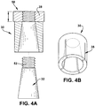
- FIG. 4 shows a similar break-out view as in FIG. 3 , except FIG. 4 illustrates an alternative embodiment of an alignment pin 50 in which the expandable sleeve section 30 and the hollowed head 28 are substantially unitary, e.g., bonded together or otherwise formed from a common piece of material such as a metal.
- the adjustment member 32 of FIGS. 3-4 is shown as including a tapered section, the adjustment member 32 (and other adjustment members described herein) can include a substantially uniform profile, e.g., a non-tapered profile.
- the adjustment member 32 in some cases may be threaded, notched, or have other surface-roughening characteristics, but in some cases may be substantially smooth.
- the adjustment member 32 is only threaded (or notched, or otherwise surface-roughened) in an upper region 52 which is sized to fit within the hollowed head 28. That is, this upper region 52 can be sized to interlock with a threaded inner surface of the hollowed head to retain the adjustment member 32 in the body of the alignment pin 50 (or other alignment pin 2 and/or alignment pin 26) described herein.
- the alignment pins (and associated alignment apparatuses) shown and described herein allow for the alignment of a turbomachine casing and diaphragm while overcoming the various shortfalls of conventional pins (and apparatuses).
- the alignment pins (and associated alignment apparatuses) according to various embodiments of the invention have the technical effect of aligning a turbomachine apparatus in a controlled and progressive manner.
Landscapes
- Engineering & Computer Science (AREA)
- General Engineering & Computer Science (AREA)
- Mechanical Engineering (AREA)
- Turbine Rotor Nozzle Sealing (AREA)
- Insertion Pins And Rivets (AREA)
- Snaps, Bayonet Connections, Set Pins, And Snap Rings (AREA)
- Structures Of Non-Positive Displacement Pumps (AREA)
Applications Claiming Priority (1)
| Application Number | Priority Date | Filing Date | Title |
|---|---|---|---|
| US13/495,221 US9028210B2 (en) | 2012-06-13 | 2012-06-13 | Turbomachine alignment pin |
Publications (3)
| Publication Number | Publication Date |
|---|---|
| EP2674630A2 EP2674630A2 (en) | 2013-12-18 |
| EP2674630A3 EP2674630A3 (en) | 2017-10-25 |
| EP2674630B1 true EP2674630B1 (en) | 2020-05-20 |
Family
ID=48578877
Family Applications (1)
| Application Number | Title | Priority Date | Filing Date |
|---|---|---|---|
| EP13171412.3A Active EP2674630B1 (en) | 2012-06-13 | 2013-06-11 | Turbomachine alignment pin |
Country Status (5)
| Country | Link |
|---|---|
| US (1) | US9028210B2 (enExample) |
| EP (1) | EP2674630B1 (enExample) |
| JP (1) | JP6280316B2 (enExample) |
| CN (1) | CN103485845B (enExample) |
| RU (1) | RU2013126617A (enExample) |
Families Citing this family (11)
| Publication number | Priority date | Publication date | Assignee | Title |
|---|---|---|---|---|
| US8919053B2 (en) | 2009-07-02 | 2014-12-30 | Zep Solar, Llc | Leveling foot apparatus, system, and method for photovoltaic arrays |
| EP2678492B1 (en) * | 2011-02-22 | 2020-09-02 | Tesla, Inc. | Mounting system and method for photovoltaic modules |
| EP2689867A1 (de) * | 2012-07-27 | 2014-01-29 | GESIPA Blindniettechnik GmbH | Verbindungselement und Setzgerät für ein Verbindungselement |
| EP2933513A1 (de) * | 2014-04-15 | 2015-10-21 | Siemens Aktiengesellschaft | Kupplungsvorrichtung zur Anbindung einer Schaltkupplung an einen Turbinenstrang |
| USD756760S1 (en) * | 2014-04-25 | 2016-05-24 | Cnh Industrial America Llc | Knife fastener |
| JP6671102B2 (ja) | 2015-02-20 | 2020-03-25 | 三菱日立パワーシステムズ株式会社 | 固定装置、回転機械、回転機械の製造方法、組立方法及び取外方法 |
| JP6527734B2 (ja) | 2015-03-26 | 2019-06-05 | 三菱日立パワーシステムズ株式会社 | 固定装置、蒸気タービン、回転機械の製造方法及び組立方法 |
| US10280773B2 (en) * | 2016-04-06 | 2019-05-07 | General Electric Company | Turbomachine alignment key and related turbomachine |
| USD844419S1 (en) | 2016-08-19 | 2019-04-02 | Solarcity Corporation | Coupling |
| US10350759B2 (en) * | 2017-08-14 | 2019-07-16 | The Boeing Company | Alignment tool for fastener feed mechanism |
| CN109238732B (zh) * | 2018-11-07 | 2024-05-10 | 河南柴油机重工有限责任公司 | 一种用于柴油机曲轴的快速拆卸式转速测量装置 |
Family Cites Families (22)
| Publication number | Priority date | Publication date | Assignee | Title |
|---|---|---|---|---|
| US1276708A (en) * | 1918-02-18 | 1918-08-27 | Auto Specialties Mfg Co | Expansion-bolt. |
| US1513669A (en) | 1922-11-25 | 1924-10-28 | Nicewarner Robert | Expansible bolt |
| US3042370A (en) * | 1957-10-07 | 1962-07-03 | Gen Motors Corp | Vane ring assembly |
| US3298725A (en) * | 1964-10-01 | 1967-01-17 | John C Boteler | High-strength fastener |
| US3373648A (en) * | 1966-06-22 | 1968-03-19 | Gross Paul M | Fasteners with expansion sleeve |
| DE2139437B1 (de) * | 1971-08-06 | 1972-10-12 | Siemens AG, 1000 Berlin u 8000 München | Vorrichtung zum gegenseitigen Ausrichten von einander zugeordne ten Maschinenteilen |
| CH592268A5 (enExample) * | 1975-07-02 | 1977-10-14 | Bbc Brown Boveri & Cie | |
| CH589799A5 (enExample) * | 1975-07-04 | 1977-07-15 | Bbc Brown Boveri & Cie | |
| US4408937A (en) * | 1979-12-31 | 1983-10-11 | Volker Hainke | Anchor bolt |
| DE3146027A1 (de) | 1981-11-20 | 1983-05-26 | Hilti AG, 9494 Schaan | Ankerbolzen mit bolzenkoerper und spreizhuelse |
| GB8416183D0 (en) | 1984-06-25 | 1984-08-01 | Avdel Ltd | Pin |
| JPS61173825U (enExample) * | 1985-04-18 | 1986-10-29 | ||
| US5271714A (en) * | 1992-07-09 | 1993-12-21 | General Electric Company | Turbine nozzle support arrangement |
| US5509782A (en) * | 1995-03-02 | 1996-04-23 | Dresser-Rand Company | Bearing case support |
| JPH1077803A (ja) * | 1996-09-04 | 1998-03-24 | Mitsubishi Heavy Ind Ltd | タービン翼環の位置決め用偏心ピン |
| US6074119A (en) * | 1996-10-01 | 2000-06-13 | Schlanger; Raphael | Connecting device including connectable members and tapered element |
| DE10012644A1 (de) * | 2000-03-15 | 2001-09-20 | Hilti Ag | Dübel |
| JP3745727B2 (ja) * | 2002-11-11 | 2006-02-15 | 川崎重工業株式会社 | タービンケーシングの位置決め機構 |
| ITMI20022418A1 (it) * | 2002-11-15 | 2004-05-16 | Nuovo Pignone Spa | Assieme migliorato di cassa interna a dispositivo di |
| US6984106B2 (en) * | 2004-01-08 | 2006-01-10 | General Electric Company | Resilent seal on leading edge of turbine inner shroud |
| GB2419168B (en) * | 2004-10-18 | 2008-08-20 | Airbus Uk Ltd | A Fastener assembly |
| FR2935430B1 (fr) * | 2008-08-26 | 2012-03-09 | Snecma | Turbine haute-pression de turbomachine amelioree, secteur de distributeur et moteur d'aeronef associes |
-
2012
- 2012-06-13 US US13/495,221 patent/US9028210B2/en not_active Expired - Fee Related
-
2013
- 2013-06-11 EP EP13171412.3A patent/EP2674630B1/en active Active
- 2013-06-11 JP JP2013122306A patent/JP6280316B2/ja not_active Expired - Fee Related
- 2013-06-11 RU RU2013126617/06A patent/RU2013126617A/ru not_active Application Discontinuation
- 2013-06-13 CN CN201310232932.4A patent/CN103485845B/zh not_active Expired - Fee Related
Non-Patent Citations (1)
| Title |
|---|
| None * |
Also Published As
| Publication number | Publication date |
|---|---|
| JP6280316B2 (ja) | 2018-02-14 |
| RU2013126617A (ru) | 2014-12-20 |
| EP2674630A3 (en) | 2017-10-25 |
| EP2674630A2 (en) | 2013-12-18 |
| CN103485845A (zh) | 2014-01-01 |
| CN103485845B (zh) | 2016-08-10 |
| US9028210B2 (en) | 2015-05-12 |
| US20130336784A1 (en) | 2013-12-19 |
| JP2013257040A (ja) | 2013-12-26 |
Similar Documents
| Publication | Publication Date | Title |
|---|---|---|
| EP2674630B1 (en) | Turbomachine alignment pin | |
| US10704404B2 (en) | Seals for a gas turbine engine assembly | |
| US10184352B2 (en) | Turbine shroud segment with integrated cooling air distribution system | |
| US10094234B2 (en) | Turbine shroud segment with buffer air seal system | |
| US9784116B2 (en) | Turbine shroud assembly | |
| US9453422B2 (en) | Device, system and method for preventing leakage in a turbine | |
| EP3557088B1 (en) | Bearing centering spring and damper | |
| US9670791B2 (en) | Flexible finger seal for sealing a gap between turbine engine components | |
| EP2900971B1 (en) | Support hanger for flexibly connecting a plurality of panels | |
| JP2012500934A (ja) | ターボ機械用の改良型高圧タービン、関連するガイドベーンセクター、ならびに関連する航空機用エンジン | |
| US20170152866A1 (en) | Stator vane system usable within a gas turbine engine | |
| US9243510B2 (en) | Floating seal | |
| EP2520765A2 (en) | Two-piece side seal with covers | |
| EP3009745A1 (en) | Floatwall panel with dilution hole cooling | |
| US20160312636A1 (en) | Fluid seal structure of heat engine including steam turbine | |
| EP3179050B1 (en) | Steam turbine rotor assembly comprising a circumferential seal, seal retaining members and a rotor key member | |
| US20210148242A1 (en) | Turbomachinery sealing apparatus and method | |
| KR20160117330A (ko) | 다중-에어포일 가이드 베인 유닛 | |
| KR101531473B1 (ko) | 회전 기계의 시일 구조 및 이를 구비한 가스 터빈 | |
| US20140366966A1 (en) | High pressure check valve flange joint | |
| US10494956B2 (en) | Fastener assembly for securing a turbomachine casing and method for securing the casing | |
| US9664068B2 (en) | Casing support block for steam turbine nozzle assembly | |
| US9650918B2 (en) | Austenitic segment for steam turbine nozzle assembly, and related assembly | |
| US10087768B2 (en) | Steam turbine rotor seal key member, related assembly and steam turbine | |
| EP1719877B1 (en) | Service pipe coupling within a gas turbine nozzle guide vane |
Legal Events
| Date | Code | Title | Description |
|---|---|---|---|
| PUAI | Public reference made under article 153(3) epc to a published international application that has entered the european phase |
Free format text: ORIGINAL CODE: 0009012 |
|
| AK | Designated contracting states |
Kind code of ref document: A2 Designated state(s): AL AT BE BG CH CY CZ DE DK EE ES FI FR GB GR HR HU IE IS IT LI LT LU LV MC MK MT NL NO PL PT RO RS SE SI SK SM TR |
|
| AX | Request for extension of the european patent |
Extension state: BA ME |
|
| PUAL | Search report despatched |
Free format text: ORIGINAL CODE: 0009013 |
|
| AK | Designated contracting states |
Kind code of ref document: A3 Designated state(s): AL AT BE BG CH CY CZ DE DK EE ES FI FR GB GR HR HU IE IS IT LI LT LU LV MC MK MT NL NO PL PT RO RS SE SI SK SM TR |
|
| AX | Request for extension of the european patent |
Extension state: BA ME |
|
| RIC1 | Information provided on ipc code assigned before grant |
Ipc: F16B 19/02 20060101AFI20170918BHEP Ipc: F16B 13/08 20060101ALI20170918BHEP Ipc: F16B 13/06 20060101ALN20170918BHEP |
|
| 17P | Request for examination filed |
Effective date: 20180425 |
|
| RBV | Designated contracting states (corrected) |
Designated state(s): AL AT BE BG CH CY CZ DE DK EE ES FI FR GB GR HR HU IE IS IT LI LT LU LV MC MK MT NL NO PL PT RO RS SE SI SK SM TR |
|
| GRAP | Despatch of communication of intention to grant a patent |
Free format text: ORIGINAL CODE: EPIDOSNIGR1 |
|
| STAA | Information on the status of an ep patent application or granted ep patent |
Free format text: STATUS: GRANT OF PATENT IS INTENDED |
|
| RIC1 | Information provided on ipc code assigned before grant |
Ipc: F16B 13/08 20060101ALI20191118BHEP Ipc: F16B 19/02 20060101AFI20191118BHEP Ipc: F16B 13/06 20060101ALN20191118BHEP |
|
| INTG | Intention to grant announced |
Effective date: 20191219 |
|
| RIN1 | Information on inventor provided before grant (corrected) |
Inventor name: SANKOLLI, PRASHANT PRABHAKAR Inventor name: BURDGICK, STEVEN SEBASTIAN |
|
| GRAS | Grant fee paid |
Free format text: ORIGINAL CODE: EPIDOSNIGR3 |
|
| GRAA | (expected) grant |
Free format text: ORIGINAL CODE: 0009210 |
|
| STAA | Information on the status of an ep patent application or granted ep patent |
Free format text: STATUS: THE PATENT HAS BEEN GRANTED |
|
| AK | Designated contracting states |
Kind code of ref document: B1 Designated state(s): AL AT BE BG CH CY CZ DE DK EE ES FI FR GB GR HR HU IE IS IT LI LT LU LV MC MK MT NL NO PL PT RO RS SE SI SK SM TR |
|
| REG | Reference to a national code |
Ref country code: GB Ref legal event code: FG4D |
|
| REG | Reference to a national code |
Ref country code: CH Ref legal event code: EP |
|
| REG | Reference to a national code |
Ref country code: DE Ref legal event code: R096 Ref document number: 602013069220 Country of ref document: DE |
|
| REG | Reference to a national code |
Ref country code: AT Ref legal event code: REF Ref document number: 1272787 Country of ref document: AT Kind code of ref document: T Effective date: 20200615 |
|
| REG | Reference to a national code |
Ref country code: LT Ref legal event code: MG4D |
|
| REG | Reference to a national code |
Ref country code: NL Ref legal event code: MP Effective date: 20200520 |
|
| PG25 | Lapsed in a contracting state [announced via postgrant information from national office to epo] |
Ref country code: SE Free format text: LAPSE BECAUSE OF FAILURE TO SUBMIT A TRANSLATION OF THE DESCRIPTION OR TO PAY THE FEE WITHIN THE PRESCRIBED TIME-LIMIT Effective date: 20200520 Ref country code: PT Free format text: LAPSE BECAUSE OF FAILURE TO SUBMIT A TRANSLATION OF THE DESCRIPTION OR TO PAY THE FEE WITHIN THE PRESCRIBED TIME-LIMIT Effective date: 20200921 Ref country code: NO Free format text: LAPSE BECAUSE OF FAILURE TO SUBMIT A TRANSLATION OF THE DESCRIPTION OR TO PAY THE FEE WITHIN THE PRESCRIBED TIME-LIMIT Effective date: 20200820 Ref country code: FI Free format text: LAPSE BECAUSE OF FAILURE TO SUBMIT A TRANSLATION OF THE DESCRIPTION OR TO PAY THE FEE WITHIN THE PRESCRIBED TIME-LIMIT Effective date: 20200520 Ref country code: GR Free format text: LAPSE BECAUSE OF FAILURE TO SUBMIT A TRANSLATION OF THE DESCRIPTION OR TO PAY THE FEE WITHIN THE PRESCRIBED TIME-LIMIT Effective date: 20200821 Ref country code: IS Free format text: LAPSE BECAUSE OF FAILURE TO SUBMIT A TRANSLATION OF THE DESCRIPTION OR TO PAY THE FEE WITHIN THE PRESCRIBED TIME-LIMIT Effective date: 20200920 Ref country code: LT Free format text: LAPSE BECAUSE OF FAILURE TO SUBMIT A TRANSLATION OF THE DESCRIPTION OR TO PAY THE FEE WITHIN THE PRESCRIBED TIME-LIMIT Effective date: 20200520 |
|
| PG25 | Lapsed in a contracting state [announced via postgrant information from national office to epo] |
Ref country code: LV Free format text: LAPSE BECAUSE OF FAILURE TO SUBMIT A TRANSLATION OF THE DESCRIPTION OR TO PAY THE FEE WITHIN THE PRESCRIBED TIME-LIMIT Effective date: 20200520 Ref country code: RS Free format text: LAPSE BECAUSE OF FAILURE TO SUBMIT A TRANSLATION OF THE DESCRIPTION OR TO PAY THE FEE WITHIN THE PRESCRIBED TIME-LIMIT Effective date: 20200520 Ref country code: BG Free format text: LAPSE BECAUSE OF FAILURE TO SUBMIT A TRANSLATION OF THE DESCRIPTION OR TO PAY THE FEE WITHIN THE PRESCRIBED TIME-LIMIT Effective date: 20200820 Ref country code: HR Free format text: LAPSE BECAUSE OF FAILURE TO SUBMIT A TRANSLATION OF THE DESCRIPTION OR TO PAY THE FEE WITHIN THE PRESCRIBED TIME-LIMIT Effective date: 20200520 |
|
| REG | Reference to a national code |
Ref country code: AT Ref legal event code: MK05 Ref document number: 1272787 Country of ref document: AT Kind code of ref document: T Effective date: 20200520 |
|
| PG25 | Lapsed in a contracting state [announced via postgrant information from national office to epo] |
Ref country code: NL Free format text: LAPSE BECAUSE OF FAILURE TO SUBMIT A TRANSLATION OF THE DESCRIPTION OR TO PAY THE FEE WITHIN THE PRESCRIBED TIME-LIMIT Effective date: 20200520 Ref country code: AL Free format text: LAPSE BECAUSE OF FAILURE TO SUBMIT A TRANSLATION OF THE DESCRIPTION OR TO PAY THE FEE WITHIN THE PRESCRIBED TIME-LIMIT Effective date: 20200520 |
|
| REG | Reference to a national code |
Ref country code: DE Ref legal event code: R119 Ref document number: 602013069220 Country of ref document: DE |
|
| PG25 | Lapsed in a contracting state [announced via postgrant information from national office to epo] |
Ref country code: RO Free format text: LAPSE BECAUSE OF FAILURE TO SUBMIT A TRANSLATION OF THE DESCRIPTION OR TO PAY THE FEE WITHIN THE PRESCRIBED TIME-LIMIT Effective date: 20200520 Ref country code: DK Free format text: LAPSE BECAUSE OF FAILURE TO SUBMIT A TRANSLATION OF THE DESCRIPTION OR TO PAY THE FEE WITHIN THE PRESCRIBED TIME-LIMIT Effective date: 20200520 Ref country code: AT Free format text: LAPSE BECAUSE OF FAILURE TO SUBMIT A TRANSLATION OF THE DESCRIPTION OR TO PAY THE FEE WITHIN THE PRESCRIBED TIME-LIMIT Effective date: 20200520 Ref country code: EE Free format text: LAPSE BECAUSE OF FAILURE TO SUBMIT A TRANSLATION OF THE DESCRIPTION OR TO PAY THE FEE WITHIN THE PRESCRIBED TIME-LIMIT Effective date: 20200520 Ref country code: SM Free format text: LAPSE BECAUSE OF FAILURE TO SUBMIT A TRANSLATION OF THE DESCRIPTION OR TO PAY THE FEE WITHIN THE PRESCRIBED TIME-LIMIT Effective date: 20200520 Ref country code: IT Free format text: LAPSE BECAUSE OF FAILURE TO SUBMIT A TRANSLATION OF THE DESCRIPTION OR TO PAY THE FEE WITHIN THE PRESCRIBED TIME-LIMIT Effective date: 20200520 Ref country code: ES Free format text: LAPSE BECAUSE OF FAILURE TO SUBMIT A TRANSLATION OF THE DESCRIPTION OR TO PAY THE FEE WITHIN THE PRESCRIBED TIME-LIMIT Effective date: 20200520 Ref country code: CZ Free format text: LAPSE BECAUSE OF FAILURE TO SUBMIT A TRANSLATION OF THE DESCRIPTION OR TO PAY THE FEE WITHIN THE PRESCRIBED TIME-LIMIT Effective date: 20200520 |
|
| REG | Reference to a national code |
Ref country code: CH Ref legal event code: PL |
|
| PG25 | Lapsed in a contracting state [announced via postgrant information from national office to epo] |
Ref country code: SK Free format text: LAPSE BECAUSE OF FAILURE TO SUBMIT A TRANSLATION OF THE DESCRIPTION OR TO PAY THE FEE WITHIN THE PRESCRIBED TIME-LIMIT Effective date: 20200520 Ref country code: PL Free format text: LAPSE BECAUSE OF FAILURE TO SUBMIT A TRANSLATION OF THE DESCRIPTION OR TO PAY THE FEE WITHIN THE PRESCRIBED TIME-LIMIT Effective date: 20200520 Ref country code: MC Free format text: LAPSE BECAUSE OF FAILURE TO SUBMIT A TRANSLATION OF THE DESCRIPTION OR TO PAY THE FEE WITHIN THE PRESCRIBED TIME-LIMIT Effective date: 20200520 |
|
| PLBE | No opposition filed within time limit |
Free format text: ORIGINAL CODE: 0009261 |
|
| STAA | Information on the status of an ep patent application or granted ep patent |
Free format text: STATUS: NO OPPOSITION FILED WITHIN TIME LIMIT |
|
| PG25 | Lapsed in a contracting state [announced via postgrant information from national office to epo] |
Ref country code: LU Free format text: LAPSE BECAUSE OF NON-PAYMENT OF DUE FEES Effective date: 20200611 |
|
| REG | Reference to a national code |
Ref country code: BE Ref legal event code: MM Effective date: 20200630 |
|
| 26N | No opposition filed |
Effective date: 20210223 |
|
| GBPC | Gb: european patent ceased through non-payment of renewal fee |
Effective date: 20200820 |
|
| PG25 | Lapsed in a contracting state [announced via postgrant information from national office to epo] |
Ref country code: FR Free format text: LAPSE BECAUSE OF NON-PAYMENT OF DUE FEES Effective date: 20200720 Ref country code: IE Free format text: LAPSE BECAUSE OF NON-PAYMENT OF DUE FEES Effective date: 20200611 Ref country code: LI Free format text: LAPSE BECAUSE OF NON-PAYMENT OF DUE FEES Effective date: 20200630 Ref country code: CH Free format text: LAPSE BECAUSE OF NON-PAYMENT OF DUE FEES Effective date: 20200630 |
|
| PG25 | Lapsed in a contracting state [announced via postgrant information from national office to epo] |
Ref country code: BE Free format text: LAPSE BECAUSE OF NON-PAYMENT OF DUE FEES Effective date: 20200630 Ref country code: DE Free format text: LAPSE BECAUSE OF NON-PAYMENT OF DUE FEES Effective date: 20210101 Ref country code: SI Free format text: LAPSE BECAUSE OF FAILURE TO SUBMIT A TRANSLATION OF THE DESCRIPTION OR TO PAY THE FEE WITHIN THE PRESCRIBED TIME-LIMIT Effective date: 20200520 |
|
| PG25 | Lapsed in a contracting state [announced via postgrant information from national office to epo] |
Ref country code: GB Free format text: LAPSE BECAUSE OF NON-PAYMENT OF DUE FEES Effective date: 20200820 |
|
| PG25 | Lapsed in a contracting state [announced via postgrant information from national office to epo] |
Ref country code: TR Free format text: LAPSE BECAUSE OF FAILURE TO SUBMIT A TRANSLATION OF THE DESCRIPTION OR TO PAY THE FEE WITHIN THE PRESCRIBED TIME-LIMIT Effective date: 20200520 Ref country code: MT Free format text: LAPSE BECAUSE OF FAILURE TO SUBMIT A TRANSLATION OF THE DESCRIPTION OR TO PAY THE FEE WITHIN THE PRESCRIBED TIME-LIMIT Effective date: 20200520 Ref country code: CY Free format text: LAPSE BECAUSE OF FAILURE TO SUBMIT A TRANSLATION OF THE DESCRIPTION OR TO PAY THE FEE WITHIN THE PRESCRIBED TIME-LIMIT Effective date: 20200520 |
|
| PG25 | Lapsed in a contracting state [announced via postgrant information from national office to epo] |
Ref country code: MK Free format text: LAPSE BECAUSE OF FAILURE TO SUBMIT A TRANSLATION OF THE DESCRIPTION OR TO PAY THE FEE WITHIN THE PRESCRIBED TIME-LIMIT Effective date: 20200520 |