EP2674607A1 - Metal ion elimination filter - Google Patents
Metal ion elimination filter Download PDFInfo
- Publication number
- EP2674607A1 EP2674607A1 EP12744449.5A EP12744449A EP2674607A1 EP 2674607 A1 EP2674607 A1 EP 2674607A1 EP 12744449 A EP12744449 A EP 12744449A EP 2674607 A1 EP2674607 A1 EP 2674607A1
- Authority
- EP
- European Patent Office
- Prior art keywords
- fuel
- ion
- exchange resin
- filter
- injector
- Prior art date
- Legal status (The legal status is an assumption and is not a legal conclusion. Google has not performed a legal analysis and makes no representation as to the accuracy of the status listed.)
- Withdrawn
Links
- 229910021645 metal ion Inorganic materials 0.000 title claims abstract description 37
- 230000008030 elimination Effects 0.000 title claims abstract description 28
- 238000003379 elimination reaction Methods 0.000 title claims abstract description 28
- 239000000446 fuel Substances 0.000 claims abstract description 113
- NWUYHJFMYQTDRP-UHFFFAOYSA-N 1,2-bis(ethenyl)benzene;1-ethenyl-2-ethylbenzene;styrene Chemical compound C=CC1=CC=CC=C1.CCC1=CC=CC=C1C=C.C=CC1=CC=CC=C1C=C NWUYHJFMYQTDRP-UHFFFAOYSA-N 0.000 claims abstract description 29
- 239000003456 ion exchange resin Substances 0.000 claims abstract description 29
- 229920003303 ion-exchange polymer Polymers 0.000 claims abstract description 29
- 239000002828 fuel tank Substances 0.000 claims abstract description 17
- 238000005342 ion exchange Methods 0.000 claims abstract description 11
- 239000002918 waste heat Substances 0.000 claims abstract description 11
- 238000001179 sorption measurement Methods 0.000 claims abstract description 4
- 238000011144 upstream manufacturing Methods 0.000 claims description 5
- 238000006243 chemical reaction Methods 0.000 description 8
- 238000010438 heat treatment Methods 0.000 description 7
- XLYOFNOQVPJJNP-UHFFFAOYSA-N water Substances O XLYOFNOQVPJJNP-UHFFFAOYSA-N 0.000 description 7
- 239000002184 metal Substances 0.000 description 6
- 238000002347 injection Methods 0.000 description 5
- 239000007924 injection Substances 0.000 description 5
- 150000003839 salts Chemical class 0.000 description 4
- 238000011045 prefiltration Methods 0.000 description 3
- 239000007787 solid Substances 0.000 description 3
- 230000000694 effects Effects 0.000 description 2
- 230000005611 electricity Effects 0.000 description 2
- 238000001816 cooling Methods 0.000 description 1
- 230000007257 malfunction Effects 0.000 description 1
- 238000004519 manufacturing process Methods 0.000 description 1
- 238000000034 method Methods 0.000 description 1
- 238000012986 modification Methods 0.000 description 1
- 230000004048 modification Effects 0.000 description 1
- 230000002265 prevention Effects 0.000 description 1
- 238000011084 recovery Methods 0.000 description 1
- 239000000243 solution Substances 0.000 description 1
Images
Classifications
-
- F—MECHANICAL ENGINEERING; LIGHTING; HEATING; WEAPONS; BLASTING
- F02—COMBUSTION ENGINES; HOT-GAS OR COMBUSTION-PRODUCT ENGINE PLANTS
- F02M—SUPPLYING COMBUSTION ENGINES IN GENERAL WITH COMBUSTIBLE MIXTURES OR CONSTITUENTS THEREOF
- F02M37/00—Apparatus or systems for feeding liquid fuel from storage containers to carburettors or fuel-injection apparatus; Arrangements for purifying liquid fuel specially adapted for, or arranged on, internal-combustion engines
- F02M37/22—Arrangements for purifying liquid fuel specially adapted for, or arranged on, internal-combustion engines, e.g. arrangements in the feeding system
- F02M37/30—Arrangements for purifying liquid fuel specially adapted for, or arranged on, internal-combustion engines, e.g. arrangements in the feeding system characterised by heating means
-
- B—PERFORMING OPERATIONS; TRANSPORTING
- B01—PHYSICAL OR CHEMICAL PROCESSES OR APPARATUS IN GENERAL
- B01J—CHEMICAL OR PHYSICAL PROCESSES, e.g. CATALYSIS OR COLLOID CHEMISTRY; THEIR RELEVANT APPARATUS
- B01J39/00—Cation exchange; Use of material as cation exchangers; Treatment of material for improving the cation exchange properties
-
- B—PERFORMING OPERATIONS; TRANSPORTING
- B01—PHYSICAL OR CHEMICAL PROCESSES OR APPARATUS IN GENERAL
- B01J—CHEMICAL OR PHYSICAL PROCESSES, e.g. CATALYSIS OR COLLOID CHEMISTRY; THEIR RELEVANT APPARATUS
- B01J47/00—Ion-exchange processes in general; Apparatus therefor
- B01J47/02—Column or bed processes
- B01J47/022—Column or bed processes characterised by the construction of the column or container
-
- B—PERFORMING OPERATIONS; TRANSPORTING
- B01—PHYSICAL OR CHEMICAL PROCESSES OR APPARATUS IN GENERAL
- B01J—CHEMICAL OR PHYSICAL PROCESSES, e.g. CATALYSIS OR COLLOID CHEMISTRY; THEIR RELEVANT APPARATUS
- B01J47/00—Ion-exchange processes in general; Apparatus therefor
- B01J47/02—Column or bed processes
- B01J47/06—Column or bed processes during which the ion-exchange material is subjected to a physical treatment, e.g. heat, electric current, irradiation or vibration
-
- F—MECHANICAL ENGINEERING; LIGHTING; HEATING; WEAPONS; BLASTING
- F02—COMBUSTION ENGINES; HOT-GAS OR COMBUSTION-PRODUCT ENGINE PLANTS
- F02M—SUPPLYING COMBUSTION ENGINES IN GENERAL WITH COMBUSTIBLE MIXTURES OR CONSTITUENTS THEREOF
- F02M37/00—Apparatus or systems for feeding liquid fuel from storage containers to carburettors or fuel-injection apparatus; Arrangements for purifying liquid fuel specially adapted for, or arranged on, internal-combustion engines
- F02M37/0047—Layout or arrangement of systems for feeding fuel
- F02M37/0052—Details on the fuel return circuit; Arrangement of pressure regulators
-
- F—MECHANICAL ENGINEERING; LIGHTING; HEATING; WEAPONS; BLASTING
- F02—COMBUSTION ENGINES; HOT-GAS OR COMBUSTION-PRODUCT ENGINE PLANTS
- F02M—SUPPLYING COMBUSTION ENGINES IN GENERAL WITH COMBUSTIBLE MIXTURES OR CONSTITUENTS THEREOF
- F02M31/00—Apparatus for thermally treating combustion-air, fuel, or fuel-air mixture
- F02M31/20—Apparatus for thermally treating combustion-air, fuel, or fuel-air mixture for cooling
-
- Y—GENERAL TAGGING OF NEW TECHNOLOGICAL DEVELOPMENTS; GENERAL TAGGING OF CROSS-SECTIONAL TECHNOLOGIES SPANNING OVER SEVERAL SECTIONS OF THE IPC; TECHNICAL SUBJECTS COVERED BY FORMER USPC CROSS-REFERENCE ART COLLECTIONS [XRACs] AND DIGESTS
- Y02—TECHNOLOGIES OR APPLICATIONS FOR MITIGATION OR ADAPTATION AGAINST CLIMATE CHANGE
- Y02T—CLIMATE CHANGE MITIGATION TECHNOLOGIES RELATED TO TRANSPORTATION
- Y02T10/00—Road transport of goods or passengers
- Y02T10/10—Internal combustion engine [ICE] based vehicles
- Y02T10/12—Improving ICE efficiencies
Definitions
- the present invention relates to a metal ion elimination filter.
- any metal ions in fuel may cause salt reaction with fuel components into solid metallic salts. Since such solid metallic salts left unattended may bring about malfunction of an injector or other slide member and/or block the fuel flow, ingenuity has been exercised in selection of constitutive members for the fuel injection and/or in surface finishing thereof so as to avoid any and all intrusion of metal ions into the fuel.
- a metal ion elimination filter for elimination of metal ions in the fuel.
- Patent Literature 1 As a prior art literature pertinent to this kind of metal ion elimination filter, there exists, for example, the following Patent Literature 1.
- any metal ions from the fuel may be attained, without submersion of the fuel into water, by use of a technique that the fuel is directly passed through ion-exchange resin having increased reaction rate of ion exchange through heating by a heater. This, however, requires the heater to be capacious for heating of the ion-exchange resin.
- the invention was made in view of the above and has its object to provide a metal ion elimination filter which can eliminate metal ions in fuel by directly passing the fuel through ion-exchange resin having increased reaction rate of ion exchange by heating the ion-exchange resin without use of a heater.
- the invention is directed to a metal ion elimination filter for elimination of metal ions in fuel, characterized in that a filter body filled therein with ion-exchange resin for adsorption of metal ions through ion exchange is incorporated in a fuel feed passage from a fuel tank to an injector, a fuel return passage for return of excessive fuel in the injector to the fuel tank being via said filter body to heat said ion-exchange resin with waste heat of the returning fuel.
- the high-temperature returning fuel from the injector to the fuel tank is heat-exchanged with the ion-exchange resin in the filter body so that the waste heat possessed by the returning fuel can be effectively utilized to heat the ion-exchange resin, leading to increased reaction rate of the ion-exchange resin.
- metal components in the fuel are adsorbed with ion exchange to the ion-exchange resin, the fuel made free from the metal components being guided to the injector.
- a fuel cooler for cooling of the fuel to be returned to the fuel tank for prevention of high temperature in the fuel tank.
- Metal ions can be eliminated in fuel by directly passing the fuel through ion-exchange resin having increased reaction rate of ion exchange through heating of the ion-exchange resin without use of a heater and with effective utilization of waste heat possessed by the returning fuel from the injector.
- the metal ion elimination filter is large-sized and has deteriorated mountability due to a heater as fitting and a problem that electricity is required for heating of the heater, leading to heavier burden on a battery.
- an operation of submerging the fuel into water is made unnecessary so that definitely cast aside is a fear that the fuel passed through the metal ion elimination filter is guided to an engine while the fuel contains moisture.
- waste heat can be effectively recovered from the fuel before the fuel is cooled by the fuel cooler and heat load of the fuel cooler can be lowered, leading to lowering in capacity of the fuel cooler.
- Fig. 1 shows the embodiment of the invention. Schematically illustrated in Fig. 1 is application of a metal ion elimination filter of the invention to a typical common rail type fuel injection device.
- fuel 2 in a fuel tank 1 is pressurized by a fuel pump 3.
- the fuel pump 3 is driven by an engine output and serves to pressurize the fuel 2 to a pressure required and feed the same to a common rail 4 for storage thereof under pressure-accumulated state, the fuel 2 in the common rail 4 being fed to injectors 5 each for each cylinder of the engine for injection into the cylinder.
- the fuel feed passage from the fuel tank 1 to the injector 5 comprises a feed conduit 7 for feed of the fuel 2 in the fuel tank 1 to the fuel pump 3 via a prefilter 6, a feed conduit 9 for recovery again via a fuel filter 8 of the fuel 2 fed to the fuel pump 3, a feed conduit 10 for feeding the fuel 2 passed through the fuel filter 8 to the common rail 4, and a feed conduit 11 for feed of the fuel 2 from the common rail 4 to the injector 5, a fuel return passage for returning the excessive fuel 2 in the injector 5 via a fuel cooler 12 to the fuel tank 1 being constituted by a return conduit 13.
- a metal ion elimination filter 14 which comprises a filter body 16 filled therein with grainy ion-exchange resin 15 for adsorption of the metal ions through ion exchange into which a portion of the return conduit 13 upstream of the fuel cooler 12 is entered for passing through the ion-exchange resin 15 such that the ion-exchange resin 15 can be heated by waste heat of the returning fuel 2.
- the high-temperature returning fuel 2 from the injector 5 to the fuel tank 1 is heat-exchanged with the ion-exchange resin 15 in the filter body 16 so that the ion-exchange resin 15 can be heated by effective utilization of waste heat possessed by the returning fuel 2, which increases the reaction rate of ion exchange in the ion-exchange resin 15.
- the metal components in the fuel 2 are adsorbed with ion exchange to the ion-exchange resin 15, the fuel 2 made free from the metal components being guided to the injector 5.
- metal ions can be eliminated in fuel 2 by directly passing the fuel 2 through ion-exchange resin 15 having increased reaction rate of ion exchange through heating of the ion-exchange resin 15 without use of a heater and with effective utilization of waste heat possessed by the returning fuel 2 from the injector 5.
- the metal ion elimination filter 14 is large-sized and has deteriorated mountability due to a heater as fitting and a problem that electricity is required for heating of the heater, leading to heavier burden on a battery.
- an operation of submerging the fuel 2 into water is made unnecessary so that definitely cast aside is a fear that the fuel 2 passed through the metal ion elimination filter 14 is guided to an engine while the fuel contains moisture.
- a metal ion elimination filter according to the invention is not limited to the above embodiment and that various changes and modifications may be made without departing from the scope of the invention.
- the metal ion elimination filter 14 may be provided likewise downstream of the prefilter 6 in the feed conduit 7.
- the metal ion elimination filter 14 may be integral with foreign-matter-removing filters such as the prefilter 6 and the fuel filter 8.
- the ion-exchange resin 15 may be heat exchanged with the returning fuel 2 through a heat exchanger or through contact of the return conduit 13 on an outer surface of the filter body 16.
Landscapes
- Chemical & Material Sciences (AREA)
- Engineering & Computer Science (AREA)
- Organic Chemistry (AREA)
- Chemical Kinetics & Catalysis (AREA)
- Combustion & Propulsion (AREA)
- Mechanical Engineering (AREA)
- General Engineering & Computer Science (AREA)
- Treatment Of Water By Ion Exchange (AREA)
- Fuel-Injection Apparatus (AREA)
- Cooling, Air Intake And Gas Exhaust, And Fuel Tank Arrangements In Propulsion Units (AREA)
- Fuel Cell (AREA)
Abstract
Description
- The present invention relates to a metal ion elimination filter.
- In a field of engine fuel injection, it has been known that any metal ions in fuel may cause salt reaction with fuel components into solid metallic salts. Since such solid metallic salts left unattended may bring about malfunction of an injector or other slide member and/or block the fuel flow, ingenuity has been exercised in selection of constitutive members for the fuel injection and/or in surface finishing thereof so as to avoid any and all intrusion of metal ions into the fuel.
- However, for example when inferior fuel originally has metal components, production of solids due to salt reaction in the fuel is unavoidable. Thus, incorporated in a fuel feed passage from a fuel tank to an injector is a metal ion elimination filter for elimination of metal ions in the fuel.
- As a prior art literature pertinent to this kind of metal ion elimination filter, there exists, for example, the following Patent Literature 1.
-
- [Patent Literature 1]
JP 2010-48248A - However, in the conventional metal ion elimination filter, fuel is passed through ion-exchange resin immersed in a water reservoir to dissolve metal components in water, metal ions dissolved in the water being adsorbed to the ion-exchange resin for elimination thereof. This requires an operation of submerging the fuel into the water; and thus, it is feared that the fuel passed through the metal ion elimination filter is guided to the engine while the fuel contains moisture.
- Alternatively, elimination of any metal ions from the fuel may be attained, without submersion of the fuel into water, by use of a technique that the fuel is directly passed through ion-exchange resin having increased reaction rate of ion exchange through heating by a heater. This, however, requires the heater to be capacious for heating of the ion-exchange resin.
- The invention was made in view of the above and has its object to provide a metal ion elimination filter which can eliminate metal ions in fuel by directly passing the fuel through ion-exchange resin having increased reaction rate of ion exchange by heating the ion-exchange resin without use of a heater.
- The invention is directed to a metal ion elimination filter for elimination of metal ions in fuel, characterized in that a filter body filled therein with ion-exchange resin for adsorption of metal ions through ion exchange is incorporated in a fuel feed passage from a fuel tank to an injector, a fuel return passage for return of excessive fuel in the injector to the fuel tank being via said filter body to heat said ion-exchange resin with waste heat of the returning fuel.
- Thus, in this manner, the high-temperature returning fuel from the injector to the fuel tank is heat-exchanged with the ion-exchange resin in the filter body so that the waste heat possessed by the returning fuel can be effectively utilized to heat the ion-exchange resin, leading to increased reaction rate of the ion-exchange resin. When the fuel in the fuel feed passage is passed through the filter body, metal components in the fuel are adsorbed with ion exchange to the ion-exchange resin, the fuel made free from the metal components being guided to the injector.
- Usually provided in the fuel return passage is a fuel cooler for cooling of the fuel to be returned to the fuel tank for prevention of high temperature in the fuel tank. Where the fuel return passage is passed through the filter body at a position upstream of the fuel cooler, then waste heat can be effectively recovered from the fuel before the fuel is cooled by the fuel cooler and heat load of the fuel cooler can be lowered.
- According to the above-mentioned metal ion elimination filter of the invention, various excellent effects can be obtained as follows.
- (I) Metal ions can be eliminated in fuel by directly passing the fuel through ion-exchange resin having increased reaction rate of ion exchange through heating of the ion-exchange resin without use of a heater and with effective utilization of waste heat possessed by the returning fuel from the injector. Thus, resolved are a problem that the metal ion elimination filter is large-sized and has deteriorated mountability due to a heater as fitting and a problem that electricity is required for heating of the heater, leading to heavier burden on a battery. Moreover, an operation of submerging the fuel into water is made unnecessary so that definitely cast aside is a fear that the fuel passed through the metal ion elimination filter is guided to an engine while the fuel contains moisture.
- (II) Where the fuel return passage is passed through the filter body at the position upstream of the fuel cooler, waste heat can be effectively recovered from the fuel before the fuel is cooled by the fuel cooler and heat load of the fuel cooler can be lowered, leading to lowering in capacity of the fuel cooler.
-
-
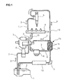
Fig. 1 is a schematic view showing an embodiment of the invention. - An embodiment of the invention will be described in conjunction with the drawing.
-
Fig. 1 shows the embodiment of the invention. Schematically illustrated inFig. 1 is application of a metal ion elimination filter of the invention to a typical common rail type fuel injection device. In the illustrated embodiment,fuel 2 in a fuel tank 1 is pressurized by afuel pump 3. - The
fuel pump 3 is driven by an engine output and serves to pressurize thefuel 2 to a pressure required and feed the same to a common rail 4 for storage thereof under pressure-accumulated state, thefuel 2 in the common rail 4 being fed toinjectors 5 each for each cylinder of the engine for injection into the cylinder. - In the fuel fed from the common rail 4 to the
injector 5,excessive fuel 2 not used for injection to the respective cylinders is returned as returningfuel 2 from therespective injectors 5 to the fuel tank 1. - The fuel feed passage from the fuel tank 1 to the
injector 5 comprises afeed conduit 7 for feed of thefuel 2 in the fuel tank 1 to thefuel pump 3 via aprefilter 6, a feed conduit 9 for recovery again via a fuel filter 8 of thefuel 2 fed to thefuel pump 3, afeed conduit 10 for feeding thefuel 2 passed through the fuel filter 8 to the common rail 4, and afeed conduit 11 for feed of thefuel 2 from the common rail 4 to theinjector 5, a fuel return passage for returning theexcessive fuel 2 in theinjector 5 via afuel cooler 12 to the fuel tank 1 being constituted by areturn conduit 13. - In the embodiment, arranged in the feed conduit 9 and downstream of the fuel filter 8 is a metal
ion elimination filter 14 which comprises afilter body 16 filled therein with grainy ion-exchange resin 15 for adsorption of the metal ions through ion exchange into which a portion of thereturn conduit 13 upstream of thefuel cooler 12 is entered for passing through the ion-exchange resin 15 such that the ion-exchange resin 15 can be heated by waste heat of the returningfuel 2. - Thus, in this manner, the high-
temperature returning fuel 2 from theinjector 5 to the fuel tank 1 is heat-exchanged with the ion-exchange resin 15 in thefilter body 16 so that the ion-exchange resin 15 can be heated by effective utilization of waste heat possessed by the returningfuel 2, which increases the reaction rate of ion exchange in the ion-exchange resin 15. Upon passage of thefuel 2 in the feed conduit 9 through thefilter body 16, the metal components in thefuel 2 are adsorbed with ion exchange to the ion-exchange resin 15, thefuel 2 made free from the metal components being guided to theinjector 5. - Thus, according to the above embodiment, metal ions can be eliminated in
fuel 2 by directly passing thefuel 2 through ion-exchange resin 15 having increased reaction rate of ion exchange through heating of the ion-exchange resin 15 without use of a heater and with effective utilization of waste heat possessed by the returningfuel 2 from theinjector 5. Thus, resolved are a problem that the metalion elimination filter 14 is large-sized and has deteriorated mountability due to a heater as fitting and a problem that electricity is required for heating of the heater, leading to heavier burden on a battery. Moreover, an operation of submerging thefuel 2 into water is made unnecessary so that definitely cast aside is a fear that thefuel 2 passed through the metalion elimination filter 14 is guided to an engine while the fuel contains moisture. - Since the
return conduit 13 is passed through thefilter body 16 at the position upstream of thefuel cooler 12, waste heat can be effectively recovered from thefuel 2 before the fuel is cooled by thefuel cooler 12 and heat load of thefuel cooler 12 can be lowered, leading to lowering in capacity of thefuel cooler 12. - It is to be understood that a metal ion elimination filter according to the invention is not limited to the above embodiment and that various changes and modifications may be made without departing from the scope of the invention. For example, the metal
ion elimination filter 14 may be provided likewise downstream of theprefilter 6 in thefeed conduit 7. The metalion elimination filter 14 may be integral with foreign-matter-removing filters such as theprefilter 6 and the fuel filter 8. The ion-exchange resin 15 may be heat exchanged with the returningfuel 2 through a heat exchanger or through contact of thereturn conduit 13 on an outer surface of thefilter body 16. -
- 1
- fuel tank
- 2
- fuel
- 3
- fuel pump
- 5
- injector
- 8
- fuel filter
- 9
- feed conduit (fuel feed passage)
- 12
- fuel cooler
- 13
- return conduit (fuel return passage)
- 14
- metal ion elimination filter
- 15
- ion-exchange resin
- 16
- filter body
Claims (2)
- A metal ion elimination filter for elimination of metal ion in fuel comprising a filter body filled therein with ion-exchange resin for adsorption of metal ions through ion exchange and incorporated in a fuel feed passage from a fuel tank to an injector, a fuel return passage for return of excessive fuel in the injector to the fuel tank being via said filter body to heat said ion-exchange resin with waste heat of the returning fuel.
- The metal ion elimination filter as claimed in claim 1, wherein the fuel return passage is passed through the filter body at a position upstream of the fuel cooler.
Applications Claiming Priority (2)
| Application Number | Priority Date | Filing Date | Title |
|---|---|---|---|
| JP2011026190A JP5778436B2 (en) | 2011-02-09 | 2011-02-09 | Metal ion removal filter |
| PCT/JP2012/000794 WO2012108176A1 (en) | 2011-02-09 | 2012-02-07 | Metal ion elimination filter |
Publications (2)
| Publication Number | Publication Date |
|---|---|
| EP2674607A1 true EP2674607A1 (en) | 2013-12-18 |
| EP2674607A4 EP2674607A4 (en) | 2015-10-28 |
Family
ID=46638397
Family Applications (1)
| Application Number | Title | Priority Date | Filing Date |
|---|---|---|---|
| EP12744449.5A Withdrawn EP2674607A4 (en) | 2011-02-09 | 2012-02-07 | METAL IONS ELIMINATION FILTER |
Country Status (5)
| Country | Link |
|---|---|
| US (1) | US20130299404A1 (en) |
| EP (1) | EP2674607A4 (en) |
| JP (1) | JP5778436B2 (en) |
| CN (1) | CN103348121B (en) |
| WO (1) | WO2012108176A1 (en) |
Families Citing this family (6)
| Publication number | Priority date | Publication date | Assignee | Title |
|---|---|---|---|---|
| CN107530590B (en) | 2015-03-17 | 2021-03-19 | 唐纳森公司 | Hydrocarbon-in-Water Purification System |
| US10604707B2 (en) | 2015-03-17 | 2020-03-31 | Donaldson Company, Inc. | Hydrocarbon-in-water purification anion-exchange system |
| CN205089502U (en) * | 2015-07-06 | 2016-03-16 | 谭大钊 | Diesel engine oil feeding system |
| MX2018014326A (en) * | 2016-05-25 | 2019-09-23 | Salus Energy Solutions L P | Hydrogenated liquid fuel production and hyperbaric fuel induction system for gasoline and diesel internal combustion engines. |
| GB2584149A (en) * | 2019-05-24 | 2020-11-25 | Delphi Tech Ip Ltd | Steel particles magnet detector |
| KR20230034689A (en) * | 2021-09-03 | 2023-03-10 | (주)바이오프랜즈 | Generator based on dme fuel |
Family Cites Families (18)
| Publication number | Priority date | Publication date | Assignee | Title |
|---|---|---|---|---|
| FR1214094A (en) * | 1959-01-23 | 1960-04-06 | Budenheim Rud A Oetker Chemie | Device for performing ion exchange treatments |
| US3315737A (en) * | 1965-04-12 | 1967-04-25 | United Aircraft Corp | Oil filter and heater |
| IT1156963B (en) * | 1978-04-17 | 1987-02-04 | Fiat Veicoli Ind | SYSTEM FOR FUEL SUPPLY TO AN INTERNAL COMBUSTION ENGINE |
| IT1217257B (en) * | 1987-08-25 | 1990-03-22 | Weber Srl | FUEL INJECTION SYSTEM WITH COMMANDED INJECTORS FOR DIESEL CYCLE ENGINES |
| US4933093A (en) * | 1989-04-20 | 1990-06-12 | Keller Russel D | Fuel filter |
| US5832902A (en) * | 1997-05-15 | 1998-11-10 | Davco Manufacturing L.L.C. | Fuel temperature control bypass circuit |
| DE19963229A1 (en) * | 1999-12-27 | 2001-06-28 | Mahle Filtersysteme Gmbh | Fuel supply device for internal combustion engine of vehicle, with through-flow heat exchanger to heat fuel going to main fuel filter |
| DE10156408B4 (en) * | 2001-11-16 | 2014-01-09 | Robert Bosch Gmbh | Fuel injection device for an internal combustion engine |
| DE202005000896U1 (en) * | 2004-11-30 | 2006-04-06 | Hengst Gmbh & Co.Kg | Ion exchanger, especially for purifying urea solutions for use in automobile exhaust emission control systems, comprises expansion chamber whose volume decreases with increase in fluid pressure |
| DE102004057631A1 (en) * | 2004-11-30 | 2006-06-01 | Mahle Filtersysteme Gmbh | Fuel supply unit for motor vehicle's internal combustion engine has ion exchange means installed inside chamber charged with fuel for removal of salts such as calcium carbonate soluble in water components of fuel |
| JP2008038615A (en) * | 2006-08-01 | 2008-02-21 | Nippon Soken Inc | Fuel supply device and injector |
| JP4984885B2 (en) * | 2006-12-27 | 2012-07-25 | 株式会社デンソー | Fuel filtration device |
| JP4960928B2 (en) * | 2007-10-05 | 2012-06-27 | 株式会社デンソー | Fuel filtration device |
| US8097049B2 (en) * | 2008-02-07 | 2012-01-17 | The Dallas Group Of America, Inc. | Biodiesel purification by a continuous regenerable adsorbent process |
| JP5195305B2 (en) | 2008-07-21 | 2013-05-08 | 株式会社デンソー | Fuel injection system |
| JP4930491B2 (en) * | 2008-11-19 | 2012-05-16 | 株式会社デンソー | Fuel filter with metal ion removal device |
| JP2010138882A (en) * | 2008-12-15 | 2010-06-24 | Denso Corp | Metal ion removing device |
| JP5563881B2 (en) * | 2010-04-27 | 2014-07-30 | 株式会社日本自動車部品総合研究所 | Fuel supply device |
-
2011
- 2011-02-09 JP JP2011026190A patent/JP5778436B2/en active Active
-
2012
- 2012-02-07 US US13/981,224 patent/US20130299404A1/en not_active Abandoned
- 2012-02-07 CN CN201280008388.9A patent/CN103348121B/en not_active Expired - Fee Related
- 2012-02-07 WO PCT/JP2012/000794 patent/WO2012108176A1/en not_active Ceased
- 2012-02-07 EP EP12744449.5A patent/EP2674607A4/en not_active Withdrawn
Also Published As
| Publication number | Publication date |
|---|---|
| US20130299404A1 (en) | 2013-11-14 |
| JP2012163084A (en) | 2012-08-30 |
| CN103348121B (en) | 2018-02-09 |
| JP5778436B2 (en) | 2015-09-16 |
| WO2012108176A1 (en) | 2012-08-16 |
| EP2674607A4 (en) | 2015-10-28 |
| CN103348121A (en) | 2013-10-09 |
Similar Documents
| Publication | Publication Date | Title |
|---|---|---|
| US20130299404A1 (en) | Metal ion elimination filter | |
| EP3058212B1 (en) | Fuel supply system for an internal combustion engine | |
| EP2907984B1 (en) | Internal combustion engine | |
| EP3292287B1 (en) | Water injection device of an internal combustion engine and method for operating such a water injection device | |
| WO2014044481A1 (en) | Coolant circuit for vehicles | |
| EP2682568B1 (en) | Heating system for a thermal electric power station water circuit | |
| DE102015118508A1 (en) | Exhaust heat recovery system and method of operating the same | |
| EP2789818A1 (en) | Drive system | |
| DE102008001090A1 (en) | An exhaust gas purifier capable of appropriately cooling a reducing agent injector | |
| WO2011157623A1 (en) | Device for preparing a reducing agent, comprising a system heating unit | |
| DE102012205001A1 (en) | Coolant circuit for internal combustion engine of vehicle, has exhaust gas heat exchanger and electrical coolant pump are arranged in third refrigerant circuit, so that coolant flows back to coolant pump is promotable | |
| DE102017210475A1 (en) | EMISSION CONTROL SYSTEM | |
| AT517368B1 (en) | Combustion engine with a heat recovery system | |
| DE202013100932U1 (en) | Intercooler system with integrated heating device | |
| EP3135876B1 (en) | Device for aftertreatment of exhaust gas | |
| CN105465767A (en) | Self-heating type deaerator with heat exchanger | |
| CN202065283U (en) | Hydraulic oil water cooling system | |
| DE102010022902A1 (en) | Method and device for operating cogeneration plants | |
| DE102014221655A1 (en) | Dosing module for introducing a fuel into a line and method for operating a dosing | |
| DE102009008744B4 (en) | Heating circuit for heating an ammonia storage device | |
| DE102018218749A1 (en) | Water injection device for an internal combustion engine | |
| DE102008042607A1 (en) | Fuel injection system for internal combustion engine of private passenger type vehicle, has fuel pump transferring fuel from tank in direction of high pressure pump, and fuel radiator placed between tank and high pressure pump in duct | |
| DE102011119242B4 (en) | An exhaust gas purification device comprising a heating system for a reducing agent storage device | |
| CN102039492A (en) | Cooling circulating system for laser welding machine | |
| EP2923072B1 (en) | Fuel injection system |
Legal Events
| Date | Code | Title | Description |
|---|---|---|---|
| PUAI | Public reference made under article 153(3) epc to a published international application that has entered the european phase |
Free format text: ORIGINAL CODE: 0009012 |
|
| 17P | Request for examination filed |
Effective date: 20130805 |
|
| AK | Designated contracting states |
Kind code of ref document: A1 Designated state(s): AL AT BE BG CH CY CZ DE DK EE ES FI FR GB GR HR HU IE IS IT LI LT LU LV MC MK MT NL NO PL PT RO RS SE SI SK SM TR |
|
| DAX | Request for extension of the european patent (deleted) | ||
| RA4 | Supplementary search report drawn up and despatched (corrected) |
Effective date: 20150924 |
|
| RIC1 | Information provided on ipc code assigned before grant |
Ipc: F02M 37/22 20060101AFI20150918BHEP Ipc: B01J 47/06 20060101ALI20150918BHEP Ipc: F02M 37/00 20060101ALI20150918BHEP Ipc: B01J 39/04 20060101ALI20150918BHEP |
|
| STAA | Information on the status of an ep patent application or granted ep patent |
Free format text: STATUS: THE APPLICATION IS DEEMED TO BE WITHDRAWN |
|
| 18D | Application deemed to be withdrawn |
Effective date: 20160426 |