EP2674561B1 - Thermally resistive window sash member and window assembly - Google Patents
Thermally resistive window sash member and window assembly Download PDFInfo
- Publication number
- EP2674561B1 EP2674561B1 EP13180878.4A EP13180878A EP2674561B1 EP 2674561 B1 EP2674561 B1 EP 2674561B1 EP 13180878 A EP13180878 A EP 13180878A EP 2674561 B1 EP2674561 B1 EP 2674561B1
- Authority
- EP
- European Patent Office
- Prior art keywords
- thermally resistive
- window
- window pane
- resistive element
- profile member
- Prior art date
- Legal status (The legal status is an assumption and is not a legal conclusion. Google has not performed a legal analysis and makes no representation as to the accuracy of the status listed.)
- Active
Links
- 230000000712 assembly Effects 0.000 description 8
- 238000000429 assembly Methods 0.000 description 8
- XAGFODPZIPBFFR-UHFFFAOYSA-N aluminium Chemical compound [Al] XAGFODPZIPBFFR-UHFFFAOYSA-N 0.000 description 5
- 229910052782 aluminium Inorganic materials 0.000 description 5
- 239000004411 aluminium Substances 0.000 description 5
- 239000000463 material Substances 0.000 description 5
- 230000005494 condensation Effects 0.000 description 1
- 238000009833 condensation Methods 0.000 description 1
- 239000011521 glass Substances 0.000 description 1
- 239000003365 glass fiber Substances 0.000 description 1
- 239000002023 wood Substances 0.000 description 1
Images


Classifications
-
- E—FIXED CONSTRUCTIONS
- E06—DOORS, WINDOWS, SHUTTERS, OR ROLLER BLINDS IN GENERAL; LADDERS
- E06B—FIXED OR MOVABLE CLOSURES FOR OPENINGS IN BUILDINGS, VEHICLES, FENCES OR LIKE ENCLOSURES IN GENERAL, e.g. DOORS, WINDOWS, BLINDS, GATES
- E06B3/00—Window sashes, door leaves, or like elements for closing wall or like openings; Layout of fixed or moving closures, e.g. windows in wall or like openings; Features of rigidly-mounted outer frames relating to the mounting of wing frames
- E06B3/04—Wing frames not characterised by the manner of movement
- E06B3/263—Frames with special provision for insulation
- E06B3/26301—Frames with special provision for insulation with prefabricated insulating strips between two metal section members
- E06B3/26305—Connection details
-
- E—FIXED CONSTRUCTIONS
- E06—DOORS, WINDOWS, SHUTTERS, OR ROLLER BLINDS IN GENERAL; LADDERS
- E06B—FIXED OR MOVABLE CLOSURES FOR OPENINGS IN BUILDINGS, VEHICLES, FENCES OR LIKE ENCLOSURES IN GENERAL, e.g. DOORS, WINDOWS, BLINDS, GATES
- E06B3/00—Window sashes, door leaves, or like elements for closing wall or like openings; Layout of fixed or moving closures, e.g. windows in wall or like openings; Features of rigidly-mounted outer frames relating to the mounting of wing frames
- E06B3/30—Coverings, e.g. protecting against weather, for decorative purposes
- E06B3/308—Wing frames covered on the outside by a rigidly-mounted outer frame
-
- E—FIXED CONSTRUCTIONS
- E06—DOORS, WINDOWS, SHUTTERS, OR ROLLER BLINDS IN GENERAL; LADDERS
- E06B—FIXED OR MOVABLE CLOSURES FOR OPENINGS IN BUILDINGS, VEHICLES, FENCES OR LIKE ENCLOSURES IN GENERAL, e.g. DOORS, WINDOWS, BLINDS, GATES
- E06B3/00—Window sashes, door leaves, or like elements for closing wall or like openings; Layout of fixed or moving closures, e.g. windows in wall or like openings; Features of rigidly-mounted outer frames relating to the mounting of wing frames
- E06B3/32—Arrangements of wings characterised by the manner of movement; Arrangements of movable wings in openings; Features of wings or frames relating solely to the manner of movement of the wing
- E06B3/325—Wings opening towards the outside
-
- E—FIXED CONSTRUCTIONS
- E06—DOORS, WINDOWS, SHUTTERS, OR ROLLER BLINDS IN GENERAL; LADDERS
- E06B—FIXED OR MOVABLE CLOSURES FOR OPENINGS IN BUILDINGS, VEHICLES, FENCES OR LIKE ENCLOSURES IN GENERAL, e.g. DOORS, WINDOWS, BLINDS, GATES
- E06B3/00—Window sashes, door leaves, or like elements for closing wall or like openings; Layout of fixed or moving closures, e.g. windows in wall or like openings; Features of rigidly-mounted outer frames relating to the mounting of wing frames
- E06B3/04—Wing frames not characterised by the manner of movement
- E06B3/263—Frames with special provision for insulation
- E06B2003/26349—Details of insulating strips
- E06B2003/2635—Specific form characteristics
- E06B2003/26352—Specific form characteristics hollow
Definitions
- the current invention relates to a profil member of a window sash for an outwardly opening window assembly. From US 5 836 119 A , US 5 038 537 A , and DE 100 59 849 A1 outwardly opening window assemblies with a relevant profile member are known.
- the profile member comprises an outer element which comprises a surface which is in contact with a portion of the outer surface of a window pane when assembled, a flange which extends at least partially underneath the window pane when assembled and means for attaching mounting hardware to said outer element, a thermally resistive element which is connected to said flange at a location between the plane of the inside surface of the window pane and the plane of the outside surface of the window pane and which extends past the plane of the inside surface of the window pane when assembled, and an inner element which is connected to said thermally resistive element and which comprises a surface which is in contact with a portion of the inside surface of the window pane when assembled. Due to the thermally resistive element arranged between the inner element and the outer element, the thermal properties of the entire window are significantly improved.
- the invention also relates to a window assembly comprising at least one thermally resistive profile member.
- a similar type of profile element is known for inwardly opening windows. See for example DE 94 12 123 U1 , FR 2 802 969 A1 , and DE 298 09 322 U1 .
- outwardly opening window assemblies have some important differences from inwardly opening windows which have made it impossible to use the thermally resistive profile members known from inwardly opening windows for outwardly opening window assemblies.
- outwardly opening windows have the mounting hardware mounted on the outside of the window and the locking hardware mounted on the inside of the window.
- hinges are mounted on the outer side of a profile member on one side of a window pane and an espagnolette is mounted on the inner side of a profile member on another side of the window pane. Therefore both the inner and the outer side of the profile members have to be strong.
- Inwardly opening window assemblies usually have both the mounting hardware and the locking hardware connected to the inner side of the profile member. It is therefore possible to use the thermally resistive profile members as disclosed above. These profiles are characterized in that they have a strong inner side made from aluminium and a weak outer side made from a thermally resistive material, for example plastic. Therefore, these profiles will not work for outwardly opening window assemblies since the thermally resistive element is not strong enough to support the loads placed on the inner element of an outwardly opening window assembly.
- a first aspect of the current invention is therefore to provide a profile member as mentioned in the opening paragraph which has better thermal properties than the currently available profile members while still being strong enough to support the loads present in an outwardly opening window assembly.
- connection between the thermally resistive element and the flange of said outer element is arranged along a connection plane which is at an angle to the plane of the window pane whereby the side of the thermally resistive element facing the centre of the window pane extends closer to the outside of the window than the side of the thermally resistive element facing away from the centre of the window pane.
- connection plane refers to the plane about which the points of connection between the thermally resistive element and the outer element are arranged. The points don't have to lie directly on the plane, but could be spaced about it.
- the flange of the outer element could be formed as an essentially horizontal hollow box shaped section, where the innermost side of said essentially horizontal hollow box shaped section can be arranged at an angle in the same direction of rotation as the connection plane and that said side can be connected to a correspondingly angled surface on the thermally resistive element.
- the strength and stiffness of the outer element can be increased. Due to the angled side, the length of the support surface can be increased thereby increasing the strength of the connection between the thermally resistive element and the outer element.
- said means for attaching mounting hardware could comprises a channel on the bottom surface of the essentially horizontal hollow box shaped section of the outer element, In order to optimize the strength of the channel, one of the channel walls could essentially be a continuation of the angled side of the essentially horizontal hollow box shaped section.
- the flange of the outer element and the thermally resistive element can be connected together by a dovetail connection.
- the outer element could comprise a supporting element which extends underneath a portion of the thermally resistive element to support the thermally resistive element against vertical loads in the downwards direction.
- the inner element could have a hollow section and the locking hardware could be arranged inside said hollow section.
- the inner element and the thermally resistive element can be integrated into a single element.
- mounting hardware is defined as the hardware which is used to hold the window sash connected to the window frame.
- hinges are considered to be mounting hardware.
- Locking hardware is defined as the hardware which keeps the window closed.
- an espagnolette is considered to be locking hardware.
- outwardly opening window assembly when used in the current specification is to be understood as a window assembly where the "sash" is located outside the “frame”. This means that even if the sash is permanently fixed to the frame, as long as the sash is outside of the frame, the window is considered to be an outwardly opening window assembly.
- thermoally resistive in this specification is to be understood as being an object having a coefficient of thermal conduction which is lower than that of aluminium.
- Figure 1 shows a typical prior art profile member 1 of a window sash of an outwardly opening window assembly.
- the profile member 1 is shown attached to one edge 2 of a double glazed window pane 3.
- the window pane 3 has an outer surface 4 and an inner surface 5.
- the profile member 1 comprises an outer element 6 which is in contact with the outer surface 4 of the window pane and an inner element 7 which is in contact with the inside surface 5 of the window pane.
- the actual contact between the window pane and the sash elements is via seals 8,9 attached to the outer and inner elements 6,7 respectively.
- the outer element 6 is considered to have a surface 8 which is in contact with the outer surface 4 of the window pane and the inner element 7 is considered to have a surface 9 which is in contact with the inner surface 5 of the window pane.
- the seals 8,9 are considered to be parts of respectively the outer and inner elements.
- the outer element 6 also comprises a flange 10 which extends underneath the edge 2 of the window pane 3 and extends from the outer surface of the window pane towards the inside of the window and past the plane 11 of the inside surface 5 of the window pane 3.
- the flange 10 is a horizontal flange, at least a part of which has a cross section in the shape of a hollow box. The hollow box gives extra strength to the profile element.
- a channel 12 is arranged whereby mounting means (not shown), such as hinges, tracks, and so on, can be attached.
- the channel 12, for the sake of the current specification, is considered to be a form of attachment means.
- the inner element 7 is connected to the portion 14 of the flange 10 which is located on the inner side of the plane 11 of the inside surface 5 of the window pane 3.
- the inner element 7 is connected to the flange via a channel 13 located on the upper side of the flange.
- the inner element 7 is made from a thermally resistive material, for example PVC, and the outer element 6 is made from aluminium for the sake of its strength properties.
- locking hardware such as an espagnolette
- the locking hardware is attached to the portion 14 of the flange 10 which is located on the inner side of the plane 11.
- the locking hardware can in some cases be partially hidden from view within the inner element 7. Therefore, in the prior art solution shown in figure 1 , it is necessary that the flange 10 of the outer element 6 is quite strong. This is because both mounting hardware and locking hardware are attachable to the flange 10.
- the inner element 7 in order to insulate the warm inside of the window assembly from the cold outer side of the window pane, it is necessary for the inner element 7 to be thermally resistive. Since the strong outer element 6 is made from aluminium, it is very thermally conductive, which means that the innermost point 15 of the outer element 6 is roughly the same temperature as the outside surface 4 of the window pane 3. The plastic inner element 7 therefore, separates the warm inner surface 5 of the window pane 3 from the cold outer element 6. However, in the prior art, the distance "d" between the inside 16 of the window assembly and the innermost point 15 of the outer element 6 is rather small. The thermal insulating properties of the window are directly affected by the size of this gap.
- the frame member 17 is typically made from wood which is very thermally resistive.
- Figure 2 shows a profile member 20 which has better thermal properties than the prior art profile member 1 shown in figure 1 .
- the profile member 20 is again shown mounted at the edge 2 of a window pane 3.
- the window pane 3 has an outer surface 4 and an inner surface 5.
- a section of a wooden window frame 17 is also shown.
- the profile member 20 comprises an outer element 21, an inner element 22, and a thermally resistive element 23.
- the outer element 21 is in contact with the outer surface 4 of the window pane 3 via a seal 8 and the inner element 22 is in contact with the inner surface 5 of the window pane 3 via a seal 9.
- the outer element 21 is made of aluminium for the sake of its strength while the inner element 22 and the thermally resistive element 23 are made from a thermally resistive material.
- the inner element 22 could be made from PVC and the thermally resistive element 23 could be made from glass fibre re-enforced PA.
- many other types of materials could also be used. The materials can be chosen as a compromise between their strength properties and their thermal properties in order that the final window assembly has the strength and thermal properties required for the specific application.
- the outer element 21 comprises a horizontal flange 24 which extends under the edge 2 of the window pane 3.
- the thermally resistive element 23 connects to the flange 24 at a location which is between the plane 25 of the outside surface 4 of the window pane 3 and the plane 26 of the inside surface 5 of the window pane 3. It can be seen that the thermally resistive element 23 can be considered as a form of "extension" of the flange 24 of the outer element 21.
- the distance "d" between the innermost point 27 of the thermally conductive outer element and the outermost point 28 of the inside surface of the window assembly is much larger than in the prior art.
- the thermal properties of a window assembly constructed from the profile elements as shown in figure 2 are much better than those of a window assembly constructed from the profile elements shown in figure 1 .
- the horizontal flange 24 of the outer element 21 is formed with a hollow box shaped portion.
- One side 29 of the hollow box shaped portion is arranged at an angle to the plane of the window pane.
- An attachment element 30 in the form of the female part of a dovetail joint is arranged on this angled side 29.
- the thermally resistive element 23 has a correspondingly angled side 31 and a corresponding attachment element 32 formed as the male part of a dovetail joint. Due to the angled surface, the area of contact between the thermally resistive element 23 and the flange 24 of the outer element 21 is increased. Due to this increased area of contact, the strength of the connection is increased. Furthermore, due to the increased length of the angled side 29, a wider dovetail joint can be used. This also increases the strength of the connection since the points of engagement of the dovetail joint are spaced further apart thereby increasing the moment which can be supported by the dovetail joint.
- the outer element 21 comprises a support element 36.
- the support element 36 is a horizontal flange which extends a short distance underneath the thermally resistive element 23.
- positive connection is defined as a connection which works in both push and pull directions.
- the support element 36 supports the thermally resistive element via the contact between a surface of the support element and a surface of the thermally resistive element. Therefore, vertical downwardly directed loads on the thermally resistive element 23 will be supported by the support element 36.
- the absence of a positive connection between the two elements 23,36 makes it easy to assemble the two elements 23,36.
- connection plane 33 could be drawn between the thermally resistive element 23 and the outer element 21. Note, the actual connection does not occur along a single plane, as is obvious from the figure. However, an imaginary "connection plane” 33 can be imagined as shown in figure 2 . It can be seen that this "connection plane” 33 is angled with respect to the window pane such that the side 34 of the thermally resistive element which is closest to the centre of the window pane 3 extends closer to the outside of the window than the side 35 of the thermally resistive element which is farthest from the centre of the window. In this way, the shortest distance between the warm inside and the cold outer element 21 is increased in comparison to a thermally resistive element having a vertical plane of connection. If the plane of connection were angled the opposite way, then the distance between the warm inside and the cold outer element 21 would be reduced.
- connection there is a single positive point of connection between the thermally resistive element 23 and the outer element 21.
- positive point of connection is meant a point of connection which prevents relative motion between the two connected elements in both pull and push directions. This is in contrast to a simple support type of connection, as is the case between the flange 36 and the thermally resistive element 23.
- the outer element 21 also comprises a channel 37 for attaching mounting means (not shown).
- the channel 37 is arranged on the bottom surface of the box shaped hollow portion of the flange 24.
- one of the sides 38 of the channel 37 is arranged to be a continuation of the angled side 29 of the hollow flange 24 of the outer element 21. In this way, the strength of the outer element 21 is further optimized.
- the inner element and the thermally resistive element are two distinct elements which are assembled during assembly of the window sash, however, in another embodiment, it could be imagined that the two elements were integrated into a single element.
- Figure 3 shows a second embodiment 40 of a profile member of a window sash of an outwardly opening window assembly.
- the second embodiment 40 is almost identical to the first embodiment 20, only the connection between the thermally resistive element 41 and the flange 42 of the outer element 43 is different, therefore, only this feature of this embodiment will be described.
- the upper surface 44 of the flange 42 of the outer element 41 is formed with an attachment element 45 in the form of the female part of a dovetail connection.
- the thermally resistive element 41 has a corresponding attachment element 46 in the form of the male part of a dovetail connection.
- the attachment element 46 extends a certain distance underneath the edge 2 of the window pane 3 towards the outside of the window in order to engage with the attachment element 45 in the upper surface of the flange 42. In this way, the connection plane 47 is further angled when compared with the first embodiment 20. This increases the strength properties of the profile.
- the thermal properties of the profile are also improved slightly with respect to the embodiment shown in figure 2 since the distance between the cold outer element and the warm inside is increased slightly.
- the outer element 43 also comprises a support element 48 to support the thermally resistive element 41 even further.
- Figure 4 shows a third embodiment 60 of a profile member.
- the profile member 60 is almost identical to the first embodiment 20. The only difference is with the support element 61. Therefore only this feature will be described here.
- the support element 61 is formed as an upwardly facing hook which extends underneath the thermally resistive element 62 and supports the thermally resistive element 62 at a point 63 instead of over a large surface as in the previous two embodiments.
- the purpose of this embodiment is to show that the support element can be formed in different ways and should not be limited to an essentially horizontal flange as in the first embodiment.
- Figure 5 shows a fourth embodiment 70 of a profile member.
- the profile member 70 is almost identical to the first embodiment 20. Therefore only the differences between this embodiment and the first embodiment 20 will be described.
- the side 71 of the flange 72 of the outer element 73 is vertical instead of angled.
- the "height" of the essentially horizontal box shaped section of the flange 72 is larger than with the previous embodiments. That is to say that the distance between the two horizontal sides 76, 77 is larger than with the previous embodiments.
- This means that the innermost side of the box shaped section is longer than with the previous embodiments, thereby allowing the "width" of the dovetail joint to be increased. This results in a strong connection even though there is no angled surface.
- This embodiment is well suited for outer elements 72 which have a "tall" flange 72. It should be noted that the strength of this embodiment is as good as the previous embodiments, however the thermal properties are not quite as good because the shortest distance between the cold outer element and the warm inside is reduced.
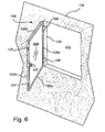
- FIG. 6 shows a schematic view of an embodiment of an outwardly opening window assembly 100 placed in an opening 101 in a wall 102.
- the window assembly 100 comprises a window frame 103, a window pane 104 and a window sash 105 arranged around the outside edge of the window pane 104.
- the window sash 105 is made up of four profile elements 105a, 105b, 105c, 105d, one along each edge of the window pane 104.
- Mounting hardware in the form of hinges 106 are connected to one of the profile elements 105d and locking hardware in the form of an espagnolette 107 is connected to another one of the profile elements 105b. This is a typical sort of outwardly opening window assembly.
- mounting hardware such as hinges
- locking hardware such as espagnolettes
- one way of improving the thermal properties of the window assembly 100 while maintaining the required strength properties of the window assembly 100 is to assemble the window sash using thermally optimized profiles 105a, 105c, 105d on the sides of the sash having no locking hardware and using a "strong" profiles 105b on the side of the sash on which locking hardware is mounted.
- the three thermally optimized profiles 105a, 105c, 105d are identical to one of the profiles shown in figures 2-5 .
- the "strong" profile 105b of the current embodiment 100 is similar to the one shown in figure 1 .
- This principle could be used with other combinations of profile elements.
- locking hardware is mounted on two profile elements.
- the window assembly could be constructed with two thermally optimized profiles and two prior art type profiles.
- the combination of elements can be chosen in such a way that the resulting thermal and strength properties of the window assembly match the desired thermal and strength properties.
Landscapes
- Engineering & Computer Science (AREA)
- Civil Engineering (AREA)
- Structural Engineering (AREA)
- Securing Of Glass Panes Or The Like (AREA)
- Wing Frames And Configurations (AREA)
- Window Of Vehicle (AREA)
Description
- The current invention relates to a profil member of a window sash for an outwardly opening window assembly. From
US 5 836 119 A ,US 5 038 537 A , andDE 100 59 849 A1 - A similar type of profile element is known for inwardly opening windows. See for example
DE 94 12 123 U1 ,FR 2 802 969 A1DE 298 09 322 U1 . However, outwardly opening window assemblies have some important differences from inwardly opening windows which have made it impossible to use the thermally resistive profile members known from inwardly opening windows for outwardly opening window assemblies. - One of these differences is that outwardly opening windows have the mounting hardware mounted on the outside of the window and the locking hardware mounted on the inside of the window. For example, hinges are mounted on the outer side of a profile member on one side of a window pane and an espagnolette is mounted on the inner side of a profile member on another side of the window pane. Therefore both the inner and the outer side of the profile members have to be strong.
- Inwardly opening window assemblies usually have both the mounting hardware and the locking hardware connected to the inner side of the profile member. It is therefore possible to use the thermally resistive profile members as disclosed above. These profiles are characterized in that they have a strong inner side made from aluminium and a weak outer side made from a thermally resistive material, for example plastic. Therefore, these profiles will not work for outwardly opening window assemblies since the thermally resistive element is not strong enough to support the loads placed on the inner element of an outwardly opening window assembly.
- A first aspect of the current invention is therefore to provide a profile member as mentioned in the opening paragraph which has better thermal properties than the currently available profile members while still being strong enough to support the loads present in an outwardly opening window assembly.
- The above mentioned aspect is solved in part by providing a profile member as mentioned in the opening paragraph where the connection between the thermally resistive element and the flange of said outer element is arranged along a connection plane which is at an angle to the plane of the window pane whereby the side of the thermally resistive element facing the centre of the window pane extends closer to the outside of the window than the side of the thermally resistive element facing away from the centre of the window pane. By arranging the connection plane in this manner, the distance between the cold outer element and the warm inside of the window can be increased. This increases the thermal properties of the window. It should be mentioned that the connection plane refers to the plane about which the points of connection between the thermally resistive element and the outer element are arranged. The points don't have to lie directly on the plane, but could be spaced about it.
- In a preferred embodiment, the flange of the outer element could be formed as an essentially horizontal hollow box shaped section, where the innermost side of said essentially horizontal hollow box shaped section can be arranged at an angle in the same direction of rotation as the connection plane and that said side can be connected to a correspondingly angled surface on the thermally resistive element. In this way, the strength and stiffness of the outer element can be increased. Due to the angled side, the length of the support surface can be increased thereby increasing the strength of the connection between the thermally resistive element and the outer element.
- In order to attach mounting hardware to the outer element said means for attaching mounting hardware could comprises a channel on the bottom surface of the essentially horizontal hollow box shaped section of the outer element, In order to optimize the strength of the channel, one of the channel walls could essentially be a continuation of the angled side of the essentially horizontal hollow box shaped section.
- In another preferred embodiment, the flange of the outer element and the thermally resistive element can be connected together by a dovetail connection.
- In order to further increase the strength of the connection between the thermally resistive element and the outer element, the outer element could comprise a supporting element which extends underneath a portion of the thermally resistive element to support the thermally resistive element against vertical loads in the downwards direction.
- In a preferred embodiment, the inner element could have a hollow section and the locking hardware could be arranged inside said hollow section. In another embodiment, the inner element and the thermally resistive element can be integrated into a single element.
- It should be mentioned that in the current specification, mounting hardware is defined as the hardware which is used to hold the window sash connected to the window frame. For example, the hinges are considered to be mounting hardware. Locking hardware is defined as the hardware which keeps the window closed. For example, an espagnolette is considered to be locking hardware.
- It should also be mentioned that the term "outwardly opening window assembly" when used in the current specification is to be understood as a window assembly where the "sash" is located outside the "frame". This means that even if the sash is permanently fixed to the frame, as long as the sash is outside of the frame, the window is considered to be an outwardly opening window assembly.
- It should also be mentioned that when a term in this specification refers to an orientation, for example, upper, lower, etc. then this term is to be interpreted with respect to the orientation of the profile members as shown in the attached figures. The terms inside and outside respectively refer to the inside and the outside of the window assembly in the case that it were installed in a house. The description "centre of the window pane" refers to the centre of the entire window pane when it is seen from the outside, it does not refer to a point between the two panes of glass in a double glazed window pane.
- In this respect it should also be mentioned, that if a feature of the profile element is described or claimed, the description or claim refers to the cross section of the profile element.
- Furthermore, an object described as being "thermally resistive" in this specification is to be understood as being an object having a coefficient of thermal conduction which is lower than that of aluminium.
- The invention will now be described in greater detail with reference to the embodiments shown in the attached figures. It is to be noted that the embodiments described herein are to be used as examples only and should not limit the scope of the invention in any way.
-
Figure 1 shows a cross section view of a prior art profile member for an outwardly opening window assembly. -
Figure 2 shows a cross section view of a first embodiment of a profile member according to the current invention for an outwardly opening window assembly. -
Figure 3 shows a cross section view of a second embodiment of a profile member according to the current invention for an outwardly opening window assembly. -
Figure 4 shows a cross section view of a third embodiment of a profile member according to the current invention for an outwardly opening window assembly. -
Figure 5 shows a cross section view of a fourth embodiment of a profile member according to the current invention for an outwardly opening window assembly. -
Figure 6 shows a perspective view of an embodiment of an outwardly opening window assembly according to one aspect of the current invention. -
Figure 1 shows a typical priorart profile member 1 of a window sash of an outwardly opening window assembly. Theprofile member 1 is shown attached to oneedge 2 of a double glazedwindow pane 3. Thewindow pane 3 has anouter surface 4 and aninner surface 5. Theprofile member 1 comprises anouter element 6 which is in contact with theouter surface 4 of the window pane and aninner element 7 which is in contact with theinside surface 5 of the window pane. The actual contact between the window pane and the sash elements is viaseals inner elements outer element 6 is considered to have asurface 8 which is in contact with theouter surface 4 of the window pane and theinner element 7 is considered to have asurface 9 which is in contact with theinner surface 5 of the window pane. In this way, theseals - The
outer element 6 also comprises aflange 10 which extends underneath theedge 2 of thewindow pane 3 and extends from the outer surface of the window pane towards the inside of the window and past theplane 11 of theinside surface 5 of thewindow pane 3. In thecurrent embodiment 1, theflange 10 is a horizontal flange, at least a part of which has a cross section in the shape of a hollow box. The hollow box gives extra strength to the profile element. On the lower side of theflange 10, achannel 12 is arranged whereby mounting means (not shown), such as hinges, tracks, and so on, can be attached. Thechannel 12, for the sake of the current specification, is considered to be a form of attachment means. - As can be seen from
figure 1 , theinner element 7 is connected to theportion 14 of theflange 10 which is located on the inner side of theplane 11 of theinside surface 5 of thewindow pane 3. Theinner element 7 is connected to the flange via achannel 13 located on the upper side of the flange. In the current embodiment, theinner element 7 is made from a thermally resistive material, for example PVC, and theouter element 6 is made from aluminium for the sake of its strength properties. - In the case where locking hardware, such as an espagnolette, is added to the window sash, the locking hardware is attached to the
portion 14 of theflange 10 which is located on the inner side of theplane 11. The locking hardware can in some cases be partially hidden from view within theinner element 7. Therefore, in the prior art solution shown infigure 1 , it is necessary that theflange 10 of theouter element 6 is quite strong. This is because both mounting hardware and locking hardware are attachable to theflange 10. - In contrast, in order to insulate the warm inside of the window assembly from the cold outer side of the window pane, it is necessary for the
inner element 7 to be thermally resistive. Since the strongouter element 6 is made from aluminium, it is very thermally conductive, which means that theinnermost point 15 of theouter element 6 is roughly the same temperature as theoutside surface 4 of thewindow pane 3. The plasticinner element 7 therefore, separates the warminner surface 5 of thewindow pane 3 from the coldouter element 6. However, in the prior art, the distance "d" between the inside 16 of the window assembly and theinnermost point 15 of theouter element 6 is rather small. The thermal insulating properties of the window are directly affected by the size of this gap. In addition, if the gap is too small and there is a large temperature difference between the inside temperature and the outside temperature, the inner surface of the window assembly will be cooled very strongly and there is a therefore a risk of condensation forming on theinner surface 5 of the window assembly. Note that theframe member 17 is typically made from wood which is very thermally resistive. - It is therefore well known that in order to increase the thermal properties of window assemblies it is desired to increase the distance "d" between the innermost point of the "cold" outer element and the inside of the window assembly. In the following, five different embodiments of profile members which have large distances "d" between the innermost point of the outer element and the inside of the window assembly are described.
-
Figure 2 shows aprofile member 20 which has better thermal properties than the priorart profile member 1 shown infigure 1 . Theprofile member 20 is again shown mounted at theedge 2 of awindow pane 3. As before thewindow pane 3 has anouter surface 4 and aninner surface 5. A section of awooden window frame 17 is also shown. - The
profile member 20 comprises anouter element 21, aninner element 22, and a thermally resistive element 23. As in the prior art, theouter element 21 is in contact with theouter surface 4 of thewindow pane 3 via aseal 8 and theinner element 22 is in contact with theinner surface 5 of thewindow pane 3 via aseal 9. Theouter element 21 is made of aluminium for the sake of its strength while theinner element 22 and the thermally resistive element 23 are made from a thermally resistive material. For example theinner element 22 could be made from PVC and the thermally resistive element 23 could be made from glass fibre re-enforced PA. However, many other types of materials could also be used. The materials can be chosen as a compromise between their strength properties and their thermal properties in order that the final window assembly has the strength and thermal properties required for the specific application. - The
outer element 21 comprises ahorizontal flange 24 which extends under theedge 2 of thewindow pane 3. The thermally resistive element 23 connects to theflange 24 at a location which is between theplane 25 of theoutside surface 4 of thewindow pane 3 and theplane 26 of theinside surface 5 of thewindow pane 3. It can be seen that the thermally resistive element 23 can be considered as a form of "extension" of theflange 24 of theouter element 21. - In this way, the distance "d" between the
innermost point 27 of the thermally conductive outer element and theoutermost point 28 of the inside surface of the window assembly is much larger than in the prior art. In this way, the thermal properties of a window assembly constructed from the profile elements as shown infigure 2 , are much better than those of a window assembly constructed from the profile elements shown infigure 1 . - The
horizontal flange 24 of theouter element 21 is formed with a hollow box shaped portion. Oneside 29 of the hollow box shaped portion is arranged at an angle to the plane of the window pane. Anattachment element 30 in the form of the female part of a dovetail joint is arranged on thisangled side 29. The thermally resistive element 23 has a correspondingly angled side 31 and acorresponding attachment element 32 formed as the male part of a dovetail joint. Due to the angled surface, the area of contact between the thermally resistive element 23 and theflange 24 of theouter element 21 is increased. Due to this increased area of contact, the strength of the connection is increased. Furthermore, due to the increased length of theangled side 29, a wider dovetail joint can be used. This also increases the strength of the connection since the points of engagement of the dovetail joint are spaced further apart thereby increasing the moment which can be supported by the dovetail joint. - In order to further support the thermally resistive elements against vertical loads, the
outer element 21 comprises asupport element 36. In this case, thesupport element 36 is a horizontal flange which extends a short distance underneath the thermally resistive element 23. There is no "positive connection" between thesupport element 36 and the thermally resistive element 23. In this specification, positive connection is defined as a connection which works in both push and pull directions. In the current embodiment, thesupport element 36 supports the thermally resistive element via the contact between a surface of the support element and a surface of the thermally resistive element. Therefore, vertical downwardly directed loads on the thermally resistive element 23 will be supported by thesupport element 36. However, the absence of a positive connection between the twoelements 23,36 makes it easy to assemble the twoelements 23,36. - Please note that a virtual "connection plane" 33 could be drawn between the thermally resistive element 23 and the
outer element 21. Note, the actual connection does not occur along a single plane, as is obvious from the figure. However, an imaginary "connection plane" 33 can be imagined as shown infigure 2 . It can be seen that this "connection plane" 33 is angled with respect to the window pane such that theside 34 of the thermally resistive element which is closest to the centre of thewindow pane 3 extends closer to the outside of the window than theside 35 of the thermally resistive element which is farthest from the centre of the window. In this way, the shortest distance between the warm inside and the coldouter element 21 is increased in comparison to a thermally resistive element having a vertical plane of connection. If the plane of connection were angled the opposite way, then the distance between the warm inside and the coldouter element 21 would be reduced. - Note that in the case of the profile element shown in
figure 2 , there is a single positive point of connection between the thermally resistive element 23 and theouter element 21. By "positive" point of connection, is meant a point of connection which prevents relative motion between the two connected elements in both pull and push directions. This is in contrast to a simple support type of connection, as is the case between theflange 36 and the thermally resistive element 23. However, it could also be imagined that instead of a single positive point of connection, there could be two positive connection points. In this case, the two connection points would be offset from each other and placed such that the "connection plane" would also be angled as in the current embodiment. - As in the prior art, the
outer element 21 also comprises achannel 37 for attaching mounting means (not shown). As was the case with the prior art profile, thechannel 37 is arranged on the bottom surface of the box shaped hollow portion of theflange 24. In this embodiment however, one of thesides 38 of thechannel 37 is arranged to be a continuation of theangled side 29 of thehollow flange 24 of theouter element 21. In this way, the strength of theouter element 21 is further optimized. - In the case of the current embodiment, the inner element and the thermally resistive element are two distinct elements which are assembled during assembly of the window sash, however, in another embodiment, it could be imagined that the two elements were integrated into a single element.
-
Figure 3 shows asecond embodiment 40 of a profile member of a window sash of an outwardly opening window assembly. Thesecond embodiment 40 is almost identical to thefirst embodiment 20, only the connection between the thermallyresistive element 41 and theflange 42 of the outer element 43 is different, therefore, only this feature of this embodiment will be described. - In this embodiment, the
upper surface 44 of theflange 42 of theouter element 41 is formed with anattachment element 45 in the form of the female part of a dovetail connection. The thermallyresistive element 41 has acorresponding attachment element 46 in the form of the male part of a dovetail connection. Theattachment element 46 extends a certain distance underneath theedge 2 of thewindow pane 3 towards the outside of the window in order to engage with theattachment element 45 in the upper surface of theflange 42. In this way, theconnection plane 47 is further angled when compared with thefirst embodiment 20. This increases the strength properties of the profile. The thermal properties of the profile are also improved slightly with respect to the embodiment shown infigure 2 since the distance between the cold outer element and the warm inside is increased slightly. - As in the
first embodiment 20, the outer element 43 also comprises asupport element 48 to support the thermallyresistive element 41 even further. -
Figure 4 shows athird embodiment 60 of a profile member. As with the previous embodiment, theprofile member 60 is almost identical to thefirst embodiment 20. The only difference is with thesupport element 61. Therefore only this feature will be described here. - In this embodiment, the
support element 61 is formed as an upwardly facing hook which extends underneath the thermallyresistive element 62 and supports the thermallyresistive element 62 at apoint 63 instead of over a large surface as in the previous two embodiments. The purpose of this embodiment is to show that the support element can be formed in different ways and should not be limited to an essentially horizontal flange as in the first embodiment. -
Figure 5 shows afourth embodiment 70 of a profile member. Again, theprofile member 70 is almost identical to thefirst embodiment 20. Therefore only the differences between this embodiment and thefirst embodiment 20 will be described. In thisembodiment 70, theside 71 of theflange 72 of theouter element 73 is vertical instead of angled. However, the "height" of the essentially horizontal box shaped section of theflange 72 is larger than with the previous embodiments. That is to say that the distance between the twohorizontal sides outer elements 72 which have a "tall"flange 72. It should be noted that the strength of this embodiment is as good as the previous embodiments, however the thermal properties are not quite as good because the shortest distance between the cold outer element and the warm inside is reduced. -
Figure 6 shows a schematic view of an embodiment of an outwardly openingwindow assembly 100 placed in anopening 101 in awall 102. Thewindow assembly 100 comprises awindow frame 103, awindow pane 104 and a window sash 105 arranged around the outside edge of thewindow pane 104. The window sash 105 is made up of fourprofile elements window pane 104. Mounting hardware in the form ofhinges 106 are connected to one of theprofile elements 105d and locking hardware in the form of anespagnolette 107 is connected to another one of theprofile elements 105b. This is a typical sort of outwardly opening window assembly. - As was previously mentioned, on outwardly opening window assemblies, mounting hardware, such as hinges, are typically attached to the outer part of the profile member and locking hardware, such as espagnolettes, are typically connected to the inner part of the profile member. It can therefore be said that a profile having a really strong connection between the inner part of the profile element and the outer part of the profile element is actually only really necessary on profile members to which locking hardware is connected.
- Therefore, according to one aspect of the current invention, one way of improving the thermal properties of the
window assembly 100 while maintaining the required strength properties of thewindow assembly 100, is to assemble the window sash using thermally optimizedprofiles profiles 105b on the side of the sash on which locking hardware is mounted. In thecurrent embodiment 100, the three thermally optimizedprofiles figures 2-5 . The "strong"profile 105b of thecurrent embodiment 100 is similar to the one shown infigure 1 . - This principle could be used with other combinations of profile elements. In certain cases, locking hardware is mounted on two profile elements. In this case, the window assembly could be constructed with two thermally optimized profiles and two prior art type profiles. In general the combination of elements can be chosen in such a way that the resulting thermal and strength properties of the window assembly match the desired thermal and strength properties.
- It should also be clear to the person skilled in the art that this aspect of the current invention, namely using a combination of "thermally optimized profiles" and "strong profiles", could be used both for outwardly opening as well as inwardly opening window assemblies.
Claims (8)
- A profile member (20, 40, 60) of a window sash for an outwardly opening window assembly, said profile member (20, 40, 60) comprising:- an outer element (21, 43) which comprises:- a surface (8) which is in contact with a portion of the outer surface (4) of a window pane (3) when assembled,- a flange (24, 42) which extends at least partially underneath the window pane (3) when assembled and- means (37) for attaching mounting hardware to said outer element (21, 43),- a thermally resistive element (23, 41, 62) which is connected to said flange (24, 42) of said outer element (21, 43) at a location between the plane (26) of the inside surface (5) of the window pane (3) and the plane (25) of the outside surface (4) of the window pane (3) and which extends past the plane (26) of the inside surface (5) of the window pane (3) when assembled, and- an inner element (22) which is connected to said thermally resistive element (23, 41, 62) and which comprises a surface (9) which is in contact with a portion of the inside surface (5) of the window pane (3) when assembled,
characterized in that the connection between the thermally resistive element (23, 41, 62) and the flange (24, 42) of said outer element (21, 43) is arranged along a connection plane (33, 47) which is at an angle to the plane of the window pane (3) whereby the side (34) of the thermally resistive element (23, 41, 62) facing the centre of the window pane (3) extends closer to the outside of the window than the side (35) of the thermally resistive element (23, 41, 62) facing away from the centre of the window pane (3). - A profile member according to claim 1, characterized in that there is a single positive point of connection between the thermally resistive element (23) and the outer element (21), wherein a positive point of connection is defined as a point of connection which prevents relative motion between the two connected elements in both pull and push directions.
- A profile member according to claim 1, characterized in that the flange (24, 42) of the outer element (21, 43) is an essentially horizontal hollow box shaped section, where the innermost side of said essentially horizontal hollow box shaped section is arranged at an angle in the same direction of rotation as the connection plane (33, 47) and that said side is connected to a correspondingly angled surface on the thermally resistive element (23).
- A profile member according to claim 2, characterized in that said means (37) for attaching mounting hardware comprises a channel (12) arranged on the bottom surface of the essentially horizontal hollow box shaped section of the outer element (21, 43) and that one of the channel walls is essentially a continuation of the angled side of the essentially horizontal hollow box shaped section.
- A profile member according to claim 1, 2 or 3, characterized in that the flange (24, 42) of the outer element (21, 43) and the thermally resistive element (23) are connected by a dovetail connection.
- A profile member according to any one of claims 1-4, characterized in that the outer element (21, 43) comprises a supporting element (36) which extends underneath a portion of the thermally resistive element (23) to support the thermally resistive element against vertical loads in the downwards direction.
- A profile member according to any one of claims 1-5, characterized in that the inner element (22) has a hollow section and that the locking hardware is arranged inside said hollow section.
- A profile member according to any one of claims 1-6, characterized in that the inner element (22) and the thermally resistive element (23) are integrated into a single element.
Priority Applications (3)
| Application Number | Priority Date | Filing Date | Title |
|---|---|---|---|
| EP13180878.4A EP2674561B1 (en) | 2006-02-08 | 2006-02-08 | Thermally resistive window sash member and window assembly |
| DK13180878.4T DK2674561T3 (en) | 2006-02-08 | 2006-02-08 | Heat resistant window frame element and window device |
| PL13180878T PL2674561T3 (en) | 2006-02-08 | 2006-02-08 | Thermally resistive window sash member and window assembly |
Applications Claiming Priority (3)
| Application Number | Priority Date | Filing Date | Title |
|---|---|---|---|
| EP13180878.4A EP2674561B1 (en) | 2006-02-08 | 2006-02-08 | Thermally resistive window sash member and window assembly |
| EP06706039.2A EP1989385B1 (en) | 2006-02-08 | 2006-02-08 | Thermally resistive window sash member and window assembly |
| DK2006000068 | 2006-02-08 |
Related Parent Applications (2)
| Application Number | Title | Priority Date | Filing Date |
|---|---|---|---|
| EP06706039.2 Division | 2006-02-08 | ||
| EP06706039.2A Division EP1989385B1 (en) | 2006-02-08 | 2006-02-08 | Thermally resistive window sash member and window assembly |
Publications (2)
| Publication Number | Publication Date |
|---|---|
| EP2674561A1 EP2674561A1 (en) | 2013-12-18 |
| EP2674561B1 true EP2674561B1 (en) | 2016-07-27 |
Family
ID=49582504
Family Applications (1)
| Application Number | Title | Priority Date | Filing Date |
|---|---|---|---|
| EP13180878.4A Active EP2674561B1 (en) | 2006-02-08 | 2006-02-08 | Thermally resistive window sash member and window assembly |
Country Status (3)
| Country | Link |
|---|---|
| EP (1) | EP2674561B1 (en) |
| DK (1) | DK2674561T3 (en) |
| PL (1) | PL2674561T3 (en) |
Family Cites Families (8)
| Publication number | Priority date | Publication date | Assignee | Title |
|---|---|---|---|---|
| US3686795A (en) * | 1967-02-28 | 1972-08-29 | Aluminum Co Of America | Windows and similar panel-supporting structures |
| US4982530A (en) * | 1988-10-14 | 1991-01-08 | Sne Enterprises, Inc. | Extruded core sections for wood fenestration mounting frames and sashes |
| US5038537A (en) * | 1989-02-21 | 1991-08-13 | Harry Frambach | Window system and structure |
| DE9412123U1 (en) | 1994-07-27 | 1994-09-29 | Ekonal Bausysteme Gmbh & Co Kg | Completion for wall openings, such as windows, doors or the like. |
| DE29809322U1 (en) | 1998-05-23 | 1998-08-13 | Goetz Metall Anlagen | Window or door construction with a frame that is fixed to the building and a pivoting casement |
| DE10059849A1 (en) * | 1999-11-30 | 2001-05-31 | Raico Bautechnik Gmbh | Fixing device for insulating window panes has support mounted on inside of overhanging edge of external pane and extending inwards to engage in frame |
| FR2802969B1 (en) | 1999-12-23 | 2003-04-11 | Ouest Alu | WINDOW OR WINDOW WINDOW WITH OPENING SHEET (S) WITH THERMAL INSULATION |
| PL367002A1 (en) * | 2001-04-10 | 2005-02-07 | Vkr Holding A/S | Fire retarding window |
-
2006
- 2006-02-08 DK DK13180878.4T patent/DK2674561T3/en active
- 2006-02-08 PL PL13180878T patent/PL2674561T3/en unknown
- 2006-02-08 EP EP13180878.4A patent/EP2674561B1/en active Active
Also Published As
| Publication number | Publication date |
|---|---|
| DK2674561T3 (en) | 2016-09-19 |
| PL2674561T3 (en) | 2017-01-31 |
| EP2674561A1 (en) | 2013-12-18 |
Similar Documents
| Publication | Publication Date | Title |
|---|---|---|
| US9091119B2 (en) | Windows and doors assembly structure having a joint portion of 45 degrees | |
| EP1989385B1 (en) | Thermally resistive window sash member and window assembly | |
| KR101672855B1 (en) | Durable curtain wall windows and doors | |
| KR101470536B1 (en) | Frame for windows and doors with excellent adiabatic effect | |
| KR101484723B1 (en) | Frame for windows and doors with excellent insulation and hermeticity | |
| EP2674561B1 (en) | Thermally resistive window sash member and window assembly | |
| KR100838967B1 (en) | Adiabatic enforced sliding window | |
| CN111895714A (en) | Swing door system and freezer device | |
| EP2211009B1 (en) | Outwardly opening window assembly | |
| US20070119112A1 (en) | Storm door with external PVC surfaces and a steel core | |
| KR101571541B1 (en) | Installation structure of windows frame | |
| JPH11280339A (en) | Upper frame construction for insulating sash | |
| KR101368355B1 (en) | High-efficiency energy-saving curtain wall | |
| KR20220150026A (en) | System Door | |
| EP3290614B1 (en) | A roof window with improved insulation properties and including a set of hinges | |
| US20200238795A1 (en) | Window assembly having flush frame to sash | |
| JP6861576B2 (en) | Joinery | |
| JP2007146652A (en) | Fitting | |
| KR101171468B1 (en) | Doorframe for Dewdrops Prevention | |
| JP3137602B2 (en) | Window sash | |
| JP2832802B2 (en) | Window frame | |
| KR101917723B1 (en) | Window frame | |
| KR102654729B1 (en) | Complex window | |
| JP6912344B2 (en) | Joinery | |
| US20070186494A1 (en) | Joinery system |
Legal Events
| Date | Code | Title | Description |
|---|---|---|---|
| PUAI | Public reference made under article 153(3) epc to a published international application that has entered the european phase |
Free format text: ORIGINAL CODE: 0009012 |
|
| AC | Divisional application: reference to earlier application |
Ref document number: 1989385 Country of ref document: EP Kind code of ref document: P |
|
| AK | Designated contracting states |
Kind code of ref document: A1 Designated state(s): AT BE BG CH CY CZ DE DK EE ES FI FR GB GR HU IE IS IT LI LT LU LV MC NL PL PT RO SE SI SK TR |
|
| AX | Request for extension of the european patent |
Extension state: AL BA HR MK YU |
|
| RIN1 | Information on inventor provided before grant (corrected) |
Inventor name: BJORN, EIRIK Inventor name: CHRISTENSEN, NIELS PETER |
|
| 17P | Request for examination filed |
Effective date: 20140616 |
|
| RBV | Designated contracting states (corrected) |
Designated state(s): AT BE BG CH CY CZ DE DK EE ES FI FR GB GR HU IE IS IT LI LT LU LV MC NL PL PT RO SE SI SK TR |
|
| GRAP | Despatch of communication of intention to grant a patent |
Free format text: ORIGINAL CODE: EPIDOSNIGR1 |
|
| INTG | Intention to grant announced |
Effective date: 20151119 |
|
| GRAS | Grant fee paid |
Free format text: ORIGINAL CODE: EPIDOSNIGR3 |
|
| GRAA | (expected) grant |
Free format text: ORIGINAL CODE: 0009210 |
|
| AC | Divisional application: reference to earlier application |
Ref document number: 1989385 Country of ref document: EP Kind code of ref document: P |
|
| AK | Designated contracting states |
Kind code of ref document: B1 Designated state(s): AT BE BG CH CY CZ DE DK EE ES FI FR GB GR HU IE IS IT LI LT LU LV MC NL PL PT RO SE SI SK TR |
|
| REG | Reference to a national code |
Ref country code: GB Ref legal event code: FG4D |
|
| REG | Reference to a national code |
Ref country code: CH Ref legal event code: EP |
|
| REG | Reference to a national code |
Ref country code: AT Ref legal event code: REF Ref document number: 815955 Country of ref document: AT Kind code of ref document: T Effective date: 20160815 |
|
| REG | Reference to a national code |
Ref country code: IE Ref legal event code: FG4D |
|
| REG | Reference to a national code |
Ref country code: DE Ref legal event code: R096 Ref document number: 602006049776 Country of ref document: DE |
|
| REG | Reference to a national code |
Ref country code: DK Ref legal event code: T3 Effective date: 20160915 |
|
| REG | Reference to a national code |
Ref country code: SE Ref legal event code: TRGR |
|
| REG | Reference to a national code |
Ref country code: LT Ref legal event code: MG4D |
|
| REG | Reference to a national code |
Ref country code: NL Ref legal event code: MP Effective date: 20160727 |
|
| REG | Reference to a national code |
Ref country code: AT Ref legal event code: MK05 Ref document number: 815955 Country of ref document: AT Kind code of ref document: T Effective date: 20160727 |
|
| PG25 | Lapsed in a contracting state [announced via postgrant information from national office to epo] |
Ref country code: IS Free format text: LAPSE BECAUSE OF FAILURE TO SUBMIT A TRANSLATION OF THE DESCRIPTION OR TO PAY THE FEE WITHIN THE PRESCRIBED TIME-LIMIT Effective date: 20161127 Ref country code: IT Free format text: LAPSE BECAUSE OF FAILURE TO SUBMIT A TRANSLATION OF THE DESCRIPTION OR TO PAY THE FEE WITHIN THE PRESCRIBED TIME-LIMIT Effective date: 20160727 Ref country code: FI Free format text: LAPSE BECAUSE OF FAILURE TO SUBMIT A TRANSLATION OF THE DESCRIPTION OR TO PAY THE FEE WITHIN THE PRESCRIBED TIME-LIMIT Effective date: 20160727 Ref country code: LT Free format text: LAPSE BECAUSE OF FAILURE TO SUBMIT A TRANSLATION OF THE DESCRIPTION OR TO PAY THE FEE WITHIN THE PRESCRIBED TIME-LIMIT Effective date: 20160727 Ref country code: NL Free format text: LAPSE BECAUSE OF FAILURE TO SUBMIT A TRANSLATION OF THE DESCRIPTION OR TO PAY THE FEE WITHIN THE PRESCRIBED TIME-LIMIT Effective date: 20160727 |
|
| PG25 | Lapsed in a contracting state [announced via postgrant information from national office to epo] |
Ref country code: LV Free format text: LAPSE BECAUSE OF FAILURE TO SUBMIT A TRANSLATION OF THE DESCRIPTION OR TO PAY THE FEE WITHIN THE PRESCRIBED TIME-LIMIT Effective date: 20160727 Ref country code: AT Free format text: LAPSE BECAUSE OF FAILURE TO SUBMIT A TRANSLATION OF THE DESCRIPTION OR TO PAY THE FEE WITHIN THE PRESCRIBED TIME-LIMIT Effective date: 20160727 Ref country code: PT Free format text: LAPSE BECAUSE OF FAILURE TO SUBMIT A TRANSLATION OF THE DESCRIPTION OR TO PAY THE FEE WITHIN THE PRESCRIBED TIME-LIMIT Effective date: 20161128 Ref country code: BE Free format text: LAPSE BECAUSE OF FAILURE TO SUBMIT A TRANSLATION OF THE DESCRIPTION OR TO PAY THE FEE WITHIN THE PRESCRIBED TIME-LIMIT Effective date: 20160727 Ref country code: ES Free format text: LAPSE BECAUSE OF FAILURE TO SUBMIT A TRANSLATION OF THE DESCRIPTION OR TO PAY THE FEE WITHIN THE PRESCRIBED TIME-LIMIT Effective date: 20160727 Ref country code: GR Free format text: LAPSE BECAUSE OF FAILURE TO SUBMIT A TRANSLATION OF THE DESCRIPTION OR TO PAY THE FEE WITHIN THE PRESCRIBED TIME-LIMIT Effective date: 20161028 |
|
| PG25 | Lapsed in a contracting state [announced via postgrant information from national office to epo] |
Ref country code: EE Free format text: LAPSE BECAUSE OF FAILURE TO SUBMIT A TRANSLATION OF THE DESCRIPTION OR TO PAY THE FEE WITHIN THE PRESCRIBED TIME-LIMIT Effective date: 20160727 Ref country code: RO Free format text: LAPSE BECAUSE OF FAILURE TO SUBMIT A TRANSLATION OF THE DESCRIPTION OR TO PAY THE FEE WITHIN THE PRESCRIBED TIME-LIMIT Effective date: 20160727 |
|
| REG | Reference to a national code |
Ref country code: DE Ref legal event code: R097 Ref document number: 602006049776 Country of ref document: DE |
|
| PG25 | Lapsed in a contracting state [announced via postgrant information from national office to epo] |
Ref country code: SK Free format text: LAPSE BECAUSE OF FAILURE TO SUBMIT A TRANSLATION OF THE DESCRIPTION OR TO PAY THE FEE WITHIN THE PRESCRIBED TIME-LIMIT Effective date: 20160727 Ref country code: BG Free format text: LAPSE BECAUSE OF FAILURE TO SUBMIT A TRANSLATION OF THE DESCRIPTION OR TO PAY THE FEE WITHIN THE PRESCRIBED TIME-LIMIT Effective date: 20161027 Ref country code: CZ Free format text: LAPSE BECAUSE OF FAILURE TO SUBMIT A TRANSLATION OF THE DESCRIPTION OR TO PAY THE FEE WITHIN THE PRESCRIBED TIME-LIMIT Effective date: 20160727 |
|
| PLBE | No opposition filed within time limit |
Free format text: ORIGINAL CODE: 0009261 |
|
| STAA | Information on the status of an ep patent application or granted ep patent |
Free format text: STATUS: NO OPPOSITION FILED WITHIN TIME LIMIT |
|
| 26N | No opposition filed |
Effective date: 20170502 |
|
| PG25 | Lapsed in a contracting state [announced via postgrant information from national office to epo] |
Ref country code: SI Free format text: LAPSE BECAUSE OF FAILURE TO SUBMIT A TRANSLATION OF THE DESCRIPTION OR TO PAY THE FEE WITHIN THE PRESCRIBED TIME-LIMIT Effective date: 20160727 |
|
| PG25 | Lapsed in a contracting state [announced via postgrant information from national office to epo] |
Ref country code: MC Free format text: LAPSE BECAUSE OF FAILURE TO SUBMIT A TRANSLATION OF THE DESCRIPTION OR TO PAY THE FEE WITHIN THE PRESCRIBED TIME-LIMIT Effective date: 20160727 |
|
| REG | Reference to a national code |
Ref country code: CH Ref legal event code: PL |
|
| PG25 | Lapsed in a contracting state [announced via postgrant information from national office to epo] |
Ref country code: LI Free format text: LAPSE BECAUSE OF NON-PAYMENT OF DUE FEES Effective date: 20170228 Ref country code: CH Free format text: LAPSE BECAUSE OF NON-PAYMENT OF DUE FEES Effective date: 20170228 |
|
| REG | Reference to a national code |
Ref country code: IE Ref legal event code: MM4A |
|
| REG | Reference to a national code |
Ref country code: FR Ref legal event code: ST Effective date: 20171031 |
|
| PG25 | Lapsed in a contracting state [announced via postgrant information from national office to epo] |
Ref country code: LU Free format text: LAPSE BECAUSE OF NON-PAYMENT OF DUE FEES Effective date: 20170208 |
|
| PG25 | Lapsed in a contracting state [announced via postgrant information from national office to epo] |
Ref country code: FR Free format text: LAPSE BECAUSE OF NON-PAYMENT OF DUE FEES Effective date: 20170228 |
|
| PG25 | Lapsed in a contracting state [announced via postgrant information from national office to epo] |
Ref country code: IE Free format text: LAPSE BECAUSE OF NON-PAYMENT OF DUE FEES Effective date: 20170208 |
|
| PGFP | Annual fee paid to national office [announced via postgrant information from national office to epo] |
Ref country code: PL Payment date: 20180112 Year of fee payment: 13 |
|
| PG25 | Lapsed in a contracting state [announced via postgrant information from national office to epo] |
Ref country code: HU Free format text: LAPSE BECAUSE OF FAILURE TO SUBMIT A TRANSLATION OF THE DESCRIPTION OR TO PAY THE FEE WITHIN THE PRESCRIBED TIME-LIMIT; INVALID AB INITIO Effective date: 20060208 |
|
| PG25 | Lapsed in a contracting state [announced via postgrant information from national office to epo] |
Ref country code: CY Free format text: LAPSE BECAUSE OF NON-PAYMENT OF DUE FEES Effective date: 20160727 |
|
| PG25 | Lapsed in a contracting state [announced via postgrant information from national office to epo] |
Ref country code: TR Free format text: LAPSE BECAUSE OF FAILURE TO SUBMIT A TRANSLATION OF THE DESCRIPTION OR TO PAY THE FEE WITHIN THE PRESCRIBED TIME-LIMIT Effective date: 20160727 |
|
| PGFP | Annual fee paid to national office [announced via postgrant information from national office to epo] |
Ref country code: SE Payment date: 20200210 Year of fee payment: 15 |
|
| PG25 | Lapsed in a contracting state [announced via postgrant information from national office to epo] |
Ref country code: PL Free format text: LAPSE BECAUSE OF NON-PAYMENT OF DUE FEES Effective date: 20190208 |
|
| PGFP | Annual fee paid to national office [announced via postgrant information from national office to epo] |
Ref country code: DE Payment date: 20210126 Year of fee payment: 16 |
|
| REG | Reference to a national code |
Ref country code: SE Ref legal event code: EUG |
|
| PG25 | Lapsed in a contracting state [announced via postgrant information from national office to epo] |
Ref country code: SE Free format text: LAPSE BECAUSE OF NON-PAYMENT OF DUE FEES Effective date: 20210209 |
|
| REG | Reference to a national code |
Ref country code: DE Ref legal event code: R119 Ref document number: 602006049776 Country of ref document: DE |
|
| PG25 | Lapsed in a contracting state [announced via postgrant information from national office to epo] |
Ref country code: DE Free format text: LAPSE BECAUSE OF NON-PAYMENT OF DUE FEES Effective date: 20220901 |
|
| PGFP | Annual fee paid to national office [announced via postgrant information from national office to epo] |
Ref country code: DK Payment date: 20230213 Year of fee payment: 18 |
|
| PGFP | Annual fee paid to national office [announced via postgrant information from national office to epo] |
Ref country code: GB Payment date: 20240104 Year of fee payment: 19 |