EP2674248B1 - Finishing device - Google Patents
Finishing device Download PDFInfo
- Publication number
- EP2674248B1 EP2674248B1 EP20120172206 EP12172206A EP2674248B1 EP 2674248 B1 EP2674248 B1 EP 2674248B1 EP 20120172206 EP20120172206 EP 20120172206 EP 12172206 A EP12172206 A EP 12172206A EP 2674248 B1 EP2674248 B1 EP 2674248B1
- Authority
- EP
- European Patent Office
- Prior art keywords
- pressure
- finishing
- guide
- recited
- elements
- Prior art date
- Legal status (The legal status is an assumption and is not a legal conclusion. Google has not performed a legal analysis and makes no representation as to the accuracy of the status listed.)
- Not-in-force
Links
Images


Classifications
-
- B—PERFORMING OPERATIONS; TRANSPORTING
- B24—GRINDING; POLISHING
- B24B—MACHINES, DEVICES, OR PROCESSES FOR GRINDING OR POLISHING; DRESSING OR CONDITIONING OF ABRADING SURFACES; FEEDING OF GRINDING, POLISHING, OR LAPPING AGENTS
- B24B5/00—Machines or devices designed for grinding surfaces of revolution on work, including those which also grind adjacent plane surfaces; Accessories therefor
- B24B5/36—Single-purpose machines or devices
- B24B5/42—Single-purpose machines or devices for grinding crankshafts or crankpins
-
- B—PERFORMING OPERATIONS; TRANSPORTING
- B24—GRINDING; POLISHING
- B24B—MACHINES, DEVICES, OR PROCESSES FOR GRINDING OR POLISHING; DRESSING OR CONDITIONING OF ABRADING SURFACES; FEEDING OF GRINDING, POLISHING, OR LAPPING AGENTS
- B24B19/00—Single-purpose machines or devices for particular grinding operations not covered by any other main group
- B24B19/08—Single-purpose machines or devices for particular grinding operations not covered by any other main group for grinding non-circular cross-sections, e.g. shafts of elliptical or polygonal cross-section
- B24B19/12—Single-purpose machines or devices for particular grinding operations not covered by any other main group for grinding non-circular cross-sections, e.g. shafts of elliptical or polygonal cross-section for grinding cams or camshafts
-
- B—PERFORMING OPERATIONS; TRANSPORTING
- B24—GRINDING; POLISHING
- B24B—MACHINES, DEVICES, OR PROCESSES FOR GRINDING OR POLISHING; DRESSING OR CONDITIONING OF ABRADING SURFACES; FEEDING OF GRINDING, POLISHING, OR LAPPING AGENTS
- B24B21/00—Machines or devices using grinding or polishing belts; Accessories therefor
- B24B21/004—Machines or devices using grinding or polishing belts; Accessories therefor using abrasive rolled strips
Definitions
- the invention relates to a finishing device, comprising a pressing device with a curved pressing surface, along which a finishing belt between a finishing tape insertion end and a finishing belt performer can be pressed against a finish to be machined workpiece.
- Such a device is for example from the US-A-5,311,704 known.
- a finishing belt is pressed against a surface section to be machined, so that an abrasive layer of the finishing belt works finishing on a workpiece surface.
- Particularly good surface qualities are achieved, making the finishing process particularly suitable for machining main bearings and connecting rod bearings of a crankshaft.
- the finishing method has the further advantage that it can be used for a large number of different shapes and sizes of workpiece surfaces.
- the disadvantage here that depending on the shape and size of a workpiece surface to be machined in each case this form and size specially adapted pressure devices must be kept, which must also have only very low tolerances and are correspondingly expensive to manufacture.
- the conversion effort when replacing a pressing device can be relatively high.
- the object of the present invention is to provide a finishing device which makes it possible to reduce the number of pressing devices to be provided for different workpieces.
- the pressing device has a first pressing element with a first Andschreib Structureabêt and a second pressing element with a second Andschreibcolourabrough, and that an adjusting device is provided for adjusting a distance of the pressing elements in a width direction of the finishing strip.
- the pressing surface has at least two pressing surface sections which can be moved relative to one another.
- the Andschreib vomabitese are each by different pressure elements whose Distance in a width direction of the finishing tape is adjustable by means of an adjusting formed.
- the width direction of the finish tape is a direction transverse to the running direction of the finish tape, in particular, a direction perpendicular to the running direction of the finish tape.
- the adjustability of the spacing of the pressing elements also has the advantage that a fine adjustment of a working width with which the finishing strip is pressed against this workpiece surface can take place for a specific workpiece surface having a certain surface width. In this way, in a manufacturing environment, it is possible to react very flexibly to problems that might occur which were not yet foreseeable in the design phase of the workpiece to be machined and / or the pressing device intended for such a workpiece.
- the pressing device advantageously comprises exactly two (that is to say only two, not more than two) pressing elements each having a pressing surface section.
- the pressing device comprises at least three (that is three or more than three) pressing elements each having a Andschreib vomabites.
- at least two (that is, only two or more or all) of the at least three pressing elements are movable relative to each other.
- a finishing belt is not pressed along the entire width against a workpiece surface.
- the Andschreibviddusabitese overlap in a direction of the finish strip at least partially, so that the finishing belt is supported along its entire width and pressed against the workpiece surface.
- mutually facing boundaries of the pressing surface sections extend in a direction which is inclined to a running direction of the finishing tape.
- an angle of inclination of the facing boundaries relative to the running direction of the finishing tape is between about 10 ° and 90 °, preferably between about 20 ° and 70 °.
- At least one pressing surface section preferably both pressing surface sections, extend or extend between the finishing tape insertion end and the finishing tape executor.
- the position of only one of the pressing elements is adjustable by means of the adjusting device.
- one may be mounted on a first, stationary pressing an adjusting device which cooperates by means of an adjusting element with the second pressing element and moves it upon movement of the adjusting element in a corresponding manner, so that a total adjustment of the relative position between the pressing elements and thus the distance of the pressing elements in Width direction of the finishing tape is made possible.
- the positions of both pressing elements can be changed by means of the adjusting device. This makes it possible to provide a stationary adjusting device, which simultaneously acts on both pressing elements and, viewed in the width direction of the finishing strip, moves them toward or away from each other.
- a guide means be provided for guiding the pressing members in the width direction of the finishing tape. This makes it possible to provide a guide of the pressing elements separately by means of a guide device, without this function (which is also conceivable) being provided simultaneously by the adjusting device.
- a movable adjusting element is provided, which cooperates via first operative portions with associated second active portions of the pressing elements. This allows a particularly simple motion coupling of a Adjustment device, which cooperates with at least two pressing elements.
- the first active sections or the second active sections are designed as sliding blocks and that the second active sections or the first active sections are formed as slotted guides for guiding the sliding blocks.
- This allows a particularly torsionally rigid translation of the movement of the adjusting element in a movement of the pressing elements.
- a translation has the advantage of a relatively fast adjustability of the distance of the pressing elements.
- a reduction has the advantage of a particularly good Feinjustageberichtkeit the distance of the pressing elements.
- the adjustment can also be realized with other components.
- eccentrics, wedges, threads, rack drives or other adjusting drives can be used.
- the adjusting device may have a self-locking, so that it is possible that the adjusting device simultaneously forms a bearing device for supporting the pressing elements.
- a pressure element holder is provided for holding the pressure elements and if a fastening device is provided for releasably securing the pressure elements to the pressure element holder.
- the attachment device may be, for example to act a clamping or clamping device.
- finishing device has a known swivel arm, by means of which the pressing device is pivotable in the direction of a workpiece and opposite thereto, it is preferred if the Andrückelementhalter connected by means of a resilient connection means with this swivel arm and / or with a carrier connected to the pivot arm is.
- This mounting of the pressure element holder has the advantage that a compensation of at least smaller position tolerances between the workpiece and the pressure surface is made possible. This is particularly advantageous in view of the adjustability of the invention resulting width of the pressure surface.
- the guide means comprises a first guide member having a first guide surface portion and a second guide member having a second guide surface portion and when an adjusting means for adjusting a distance of the guide elements in the width direction of the finishing tape is provided.
- the adjusting device for adjusting the spacing of the guide elements can be provided in the form of a second adjusting device.
- the first pressure element and the first guide element are immovably connected to each other when the second pressure element and the second guide member are immovably connected to each other and if a common adjustment is provided to adjust the distance of the pressing of our setting the distance of the guide elements.
- this adjustment device may have a construction already explained above with reference to the adjustment device for setting the spacing of the pressure elements.
- the finishing device 10 comprises a first pivot arm 12, which is pivotable about a first pivot axis 14.
- a pivot drive 16 is provided for pivoting the pivot arm 12 about the pivot axis 14.
- the finishing device 10 has a second pivot arm 18, which is pivotable about a second pivot axis 20.
- the pivot arms 12 and 18 are coupled by means of an intermediate gear 22, for example in the form of a coupling member, so that a pivoting movement of the first pivot arm in a certain pivoting direction about the pivot axis 14 in a counteracting thereto pivotal movement of the pivot arm of the second pivot arm 18 about the second pivot axis 20th is transmitted.
- the pivot arms 12 and 18 each serve to arrange a pressure device 24 described in detail below.
- pivot arms 12 and 18 also serve for fastening a finishing band guide 26 for guiding a finishing belt 28, respectively.
- the finishing belt 28 is fed by means of a first guide device 26 to a first pressing device 24, deflected in the region of a deflection device 29 arranged, for example, on the pivoting arms 12 and / or 18, and from there fed to a second pressing device 24 and finally to a second finishing belt guide 26.
- the first pressing means 24 and the second pressing means 24 are identical to each other, so that a high number of identical parts can be used.
- FIG. 2 the arranged on the second pivot arm 18 Andrück pain 24 is shown in perspective.
- the pressing device 24 has a carrier 30 for rigid connection with the swivel arm 18.
- a pressure element holder 32 is mounted in particular elastically.
- the pressing element holder 32 serves to hold a first pressing element 34 and a second pressing element 36.
- the pressing element 34 has a first, curved pressing surface section 38.
- the second pressing element has a second, curved pressing surface section 40.
- the Andschreibdonabête 38 and 40 together form a curved pressing surface 42nd
- Both press surface portions 38 and 40 extend between a finish tape inserter 44 and a finish belt performer 46.
- roll-shaped wear elements 48, 50 are provided on which the back side of a finishing tape (not shown) slides.
- Each of the pressing elements 34, 36 has in each case a short wear element 48 and a long wear element 50.
- a course of the finishing tape is in FIG. 2 shown schematically and designated by the reference numeral 52.
- a first guide means 54 In the direction 52 upstream of the finishing tape insertion end 44 is a first guide means 54 and in the direction 52 after the finishing belt-Ausquestde 46 is a second guide means 56 for guiding the finishing tape 28 is provided.
- the guide devices 54, 56 are each in two parts and each have a first guide element 58 and a second guide element 60.
- the first guide element 58 has a particularly curved first guide surface section 62, which in particular faces the second guide element 60.
- the second guide element 60 has a second guide surface section 64, which is in particular curved and in particular faces the first guide element 58.
- the first guide elements 58 of a guide device 54, 56 are each by means of a holder 68 with the first Pressing element 34 connected.
- the second guide elements 60 are each connected to the second pressure element 36 by means of a holder 70.
- the distance of the pressing elements 34 and 36 is adjustable in a direction indicated by the reference numeral 72 width direction of the finishing tape 28, which extends transversely, in particular perpendicular, to the running direction 52 of the finishing tape 28.
- FIG. 2 a relative position of the pressing elements 34 and 36 is shown, in which the pressing elements 34 and 36 have a smallest possible distance of "zero".
- the pressing elements 34 and 36 abut each other and form with their Andschreibdonabismeen 38 and 40, a closed pressing surface 42nd
- the distance between the pressing elements 34 and 36 in the width direction 72 of the finishing belt 28 is adjustable.
- FIG. 3 shows a relative position of the pressing members 34 and 36, in which the pressing members 34 and 36 are not abutting each other, but are relatively spaced so that between the Andschreibdonabitesen 38 and 40, a gap 73 is present, which seen the guide surface 42 in the width direction 72 of the finishing belt 28 interrupts.
- the gap 73 preferably extends between the finish tape inserter 44 and the finish belt performer 46.
- a boundary of the first pressing element 34 facing the second pressing surface section 40 of the second pressing element 36 is designated by the reference numeral 74.
- a boundary of the second pressing surface section 40 facing the first pressing surface section 38 of the first pressing element 34 is designated by the reference numeral 76.
- the boundaries 74, 76 are complementary to each other, so that in a position in which the Andschreibinciabitese 38 and 40 have a smallest possible distance from each other, abut each other and no gap 73 between the pressing elements 34 and 36 is formed. In this relative position of the pressing elements 38 and 40, a continuous pressing surface 42 is formed with a first guide width 78 measured parallel to the width direction 72.
- the boundaries 74 and 76 have a measured relative to the direction 52 of the finishing belt 28 angle of inclination 81.
- This inclination angle 81 is adjusted to the dimensions of the Andschreibdonabête 38 and 40 so small that the Andschreibdonabête 38 and 40 of both Andschreibiata 34 and 36 respectively between the finishing tape insertion end 44 and the finishing tape-Ausendde 46 extend.
- the inclination angle 81 is so large that a between the finishing tape insertion end 44 and the finishing belt performer 46 arranged portion of a finishing tape 28 along the entire guide width 80 is pressed against a workpiece to be machined. This means that the Andschreibdonabbalde 38 and 40 overlap seen in the direction 52 of the finishing belt 28 at least partially.
- the pressing elements 34 and 36 are each connected to guide elements 58, 60 of a guide device 54, 56, there is a minimum guide width 82 (see FIG. 6 ), which corresponds to the minimum distance of the guide surface portions 62 and 64, then on, although the Andrückbreite 78 (see FIG. 4 ) is minimal.
- FIGS. 8 and 9 is the pressing device 24 according to section VIII (see FIG. 1 ), each with the in FIGS. 4 and 5 shown relative positions of the pressing elements 34 and 36, wherein additionally shown in dashed lines parts of an adjusting device 86 described below, by means of which the distance of the pressing elements 34 and 36 in the width direction 72 is adjustable.
- the adjusting device 86 comprises an assembly 90 which can be moved along a setting axis 88 (see FIG Figures 10 and 11 ).
- the assembly 90 comprises an adjusting element 92, which first operative portions 94 (see FIG FIGS. 14 and 15 ), which are formed in particular in the form of sliding blocks 96.
- the first active sections 94 of the adjusting element 96 cooperate with second active sections 98 of the pressing elements 34 and 36 (see FIG FIGS. 14 and 15 ).
- the second active sections are designed in particular in the form of slotted guides 100, in which the sliding blocks 96 of the first active sections 94 are displaceably guided and preferably at least largely free of play.
- the first active portions 96 of the adjusting member 92 have a fixed distance relative to each other. For this reason, a displacement of the adjusting member 92 from the in FIG. 10 illustrated situation (compare also FIG. 14 ) in the in FIG. 11 shown situation (compare also FIG. 15 ) associated with the fact that the distance between the pressing elements 34 and 36 changed (see FIGS. 12 and 13 such as FIGS. 14 and 15 ).
- the ratio of the movement of the adjustment member 92 along the adjustment axis 88 relative to a change in the spacing of the pressure members 34 and 36 may be affected by the choice of the inclination of the slide guides 100 relative to the adjustment axis 88.
- relatively low inclination of the slotted guides 100 relative to the adjustment axis 88 allow a particularly good fine adjustment of the relative position of the pressing elements 34 and 36th
- the assembly 90 cooperates via a pair of threads 102 with an actuating element 104.
- the actuator 104 has an actuating portion 106 (for example, a hexagon surface) for engaging a hand-operated or motor-operated tool.
- the actuating element 104 comprises a bearing 108, by means of which the actuating element 104 is rotatably mounted on the Andrückelementhalter 32.
- a rotation of the actuating element 104 is accompanied by a displacement of the assembly 90 along the adjustment axis 88 without the position of the actuating element 104 changing along the adjustment axis 88.
- the assembly 90 is provided with a reference element 110 (cf. Figures 2 and 3 ) connected.
- the reference member 110 moves along the adjustment axis 88 parallel to a display scale 112, which is connected to the Andschreibelementhalter 32 upon movement of the assembly 90.
- the guide device 114 comprises a plurality of guide pins 116, which are arranged in particular approximately at the level of the finishing tape insertion end 44 and / or approximately at the level of the finishing tape-Ausachedes 46 of the pressing members 34, 36.
- the fixing of the guide pins takes place in each case to that pressing element 34, 36, which has a narrower width in the fixing region, so that the non-fixed part of the guide pin with a maximum guide path for guiding the respective other pressing element is available.
- the adjusting device 86 and / or the guide device 114 are self-locking, so that a fastening device described below for fastening the pressing elements 34, 36 to the Andrückelementhalter 32 is not required.
- a fastening device designated in the following generally by the reference numeral 118, is provided.
- the fastening device 118 advantageously comprises two clamping elements 120, 122, by means of which the pressing elements 34, 36 can be clamped in a space extending parallel to the course direction 52 of the finishing strip 28.
- the clamping elements 120, 122 are each braced via a screw 124, 126 with the Andschreibelementhalter 32.
- At least one of the clamping elements 120, 122 has a wedge surface 128, which cooperates with a corresponding wedge surface of a wedge element 130, which is movable as part of a screw connection 124 and / or 126 in the direction of the carrier 30.
- the pressing elements 34, 36 are pressed against a contact surface 132 of the Andrückelementhalters 32 and at the same time clamped in a direction parallel to the contact surface 132 direction between the clamping elements 120 and 122.
- the fastening device 118 is loosened by loosening the threaded connections 124, 126, so that the pressing elements 34, 36 parallel to the contact surface 132 and can be moved transversely to the course direction 52 of the finishing belt and in their distance by means of the adjusting device 86 are adjustable.
- the pressing elements 34, 36 can be fixed again by actuating the screw connections 124, 126.
- the connecting device 134 comprises a relative to the pressing surface 42 approximately centrally arranged connecting screw 136 which is mounted for example on the Andschreibelementhalter 32 and bolted to the carrier 30.
- a clamping portion 138 of the Andschreibelementhalters 32 between spring washers 140 or a package of spring washers 140 and a spherical cap 142 is clamped.
- the spherical cap 142 cooperates with a ball socket 144 mounted on the carrier 30.
- the pressure element holder 32 is laterally clamped between leaf springs 146 (see FIG FIG. 2 ).
- the leaf springs 146 are fixed in particular to the carrier 30.
- the connecting device 134 further comprises elastic shock absorbers 148, which are formed for example in the form of elastomeric buffers.
- the shock absorbers 148 are arranged spaced relative to the central bearing.
- a further improved connection between the support 30 and the pressure element holder 32 results when the resilient support means 150 arranged as far as possible and acting between the support 30 and the pressure element holder 32 are provided.
- These include, for example, springs 152, which are respectively fixed between stops 154, 156.
- one of the stops 154, 156 is connected to one of the carrier 30 or pressing element holder 32.
- the stops 154 and 156 may be formed, for example in the form of screws whose shaft are encompassed by a respective free end 158 of the spring 152.
Landscapes
- Engineering & Computer Science (AREA)
- Mechanical Engineering (AREA)
- Finish Polishing, Edge Sharpening, And Grinding By Specific Grinding Devices (AREA)
- Sewing Machines And Sewing (AREA)
Description
Die Erfindung betrifft eine Finishvorrichtung, umfassend eine Andrückeinrichtung mit einer gekrümmten Andrückfläche, entlang welcher ein Finishband zwischen einem Finishband-Einführende und einem Finishband-Ausführende gegen ein finishend zu bearbeitendes Werkstück andrückbar ist.The invention relates to a finishing device, comprising a pressing device with a curved pressing surface, along which a finishing belt between a finishing tape insertion end and a finishing belt performer can be pressed against a finish to be machined workpiece.
Eine derartige Vorrichtung ist z.B. aus der
Bei einer Finishvorrichtung der eingangs genannten Art wird ein Finishband gegen einen zu bearbeitenden Oberflächenabschnitt gedrückt, sodass eine abrasiv wirkende Schicht des Finishbands eine Werkstückoberfläche finishend bearbeitet. Hierbei werden besonders gute Oberflächenqualitäten erzielt, sodass das Finishverfahren sich besonders gut zur Bearbeitung von Hauptlagern und Pleuellagern einer Kurbelwelle eignet.In a finishing device of the type mentioned above, a finishing belt is pressed against a surface section to be machined, so that an abrasive layer of the finishing belt works finishing on a workpiece surface. Particularly good surface qualities are achieved, making the finishing process particularly suitable for machining main bearings and connecting rod bearings of a crankshaft.
Das Finishverfahren hat den weiteren Vorteil, dass es für eine Vielzahl unterschiedlicher Formen und Größen von Werkstückoberflächen einsetzbar ist. Nachteilig hierbei jedoch ist, dass in Abhängigkeit der Form und Größe einer zu bearbeitenden Werkstückoberfläche jeweils dieser Form und Größe speziell angepasste Andrückeinrichtungen vorgehalten werden müssen, die darüber hinaus auch nur sehr niedrige Toleranzen aufweisen dürfen und entsprechend aufwändig zu fertigen sind. Darüber hinaus kann auch der Umrüstaufwand bei Austausch einer Andrückeinrichtung relativ hoch sein. Schließlich ist es insbesondere bei einer relativ kleinen Form- und/oder Größenstufung einer Vielzahl von Andrückeinrichtungen möglich, dass eine falsche, also nicht passende Andrückeinrichtung montiert wird.The finishing method has the further advantage that it can be used for a large number of different shapes and sizes of workpiece surfaces. The disadvantage here, however, that depending on the shape and size of a workpiece surface to be machined in each case this form and size specially adapted pressure devices must be kept, which must also have only very low tolerances and are correspondingly expensive to manufacture. In addition, the conversion effort when replacing a pressing device can be relatively high. Finally, it is possible in particular with a relatively small shape and / or size gradation of a plurality of pressure devices that a wrong, so not matching pressure device is mounted.
Hiervon ausgehend liegt der vorliegenden Erfindung die Aufgabe zugrunde, eine Finishvorrichtung anzugeben, welche es ermöglicht, die Anzahl der für unterschiedliche Werkstücke bereitzuhaltenden Andrückeinrichtungen zu reduzieren.Proceeding from this, the object of the present invention is to provide a finishing device which makes it possible to reduce the number of pressing devices to be provided for different workpieces.
Diese Aufgabe wird bei einer eingangs genannten Finishvorrichtung erfindungsgemäß dadurch gelöst, dass die Andrückeinrichtung ein erstes Andrückelement mit einem ersten Andrückflächenabschnitt und ein zweites Andrückelement mit einem zweiten Andrückflächenabschnitt aufweist, und dass eine Einstelleinrichtung zur Einstellung eines Abstands der Andrückelemente in einer Breitenrichtung des Finishbands vorgesehen ist.This object is achieved according to the invention in a finishing device mentioned above in that the pressing device has a first pressing element with a first Andrückflächeabschnitt and a second pressing element with a second Andrückflächenabschnitt, and that an adjusting device is provided for adjusting a distance of the pressing elements in a width direction of the finishing strip.
Bei der erfindungsgemäßen Finishvorrichtung weist die Andrückfläche mindestens zwei relativ zueinander bewegbare Andrückflächenabschnitte auf. Die Andrückflächenabschnitte sind jeweils durch unterschiedliche Andrückelemente, deren Abstand in einer Breitenrichtung des Finishbands mittels einer Einstelleinrichtung einstellbar ist, gebildet.In the case of the finishing device according to the invention, the pressing surface has at least two pressing surface sections which can be moved relative to one another. The Andrückflächenabschnitte are each by different pressure elements whose Distance in a width direction of the finishing tape is adjustable by means of an adjusting formed.
Die Breitenrichtung des Finishbands ist eine Richtung quer zu der Verlaufsrichtung des Finishbands, insbesondere eine Richtung senkrecht zu der Verlaufsrichtung des Finishbands.The width direction of the finish tape is a direction transverse to the running direction of the finish tape, in particular, a direction perpendicular to the running direction of the finish tape.
Durch die mehrteilige Ausbildung der Andrückfläche und die relativ zueinander bewegbare Anordnung der Andrückflächenabschnitte ist es zum Beispiel möglich, mittels einer bestimmten Andrückeinrichtung unterschiedlich breite Werkstückoberflächen zu bearbeiten. Die Einstellbarkeit des Abstands der Andrückelemente hat aber auch den Vorteil, dass für eine bestimmte Werkstückoberfläche mit einer bestimmten Oberflächenbreite eine Feinjustage einer Wirkbreite, mit welcher das Finishband gegen diese Werkstückoberfläche angedrückt wird, erfolgen kann. Auf diese Weise kann in einer Fertigungsumgebung sehr flexibel auf möglicherweise auftretende Probleme reagiert werden, welche in der Konstruktionsphase des zu bearbeitenden Werkstücks und/oder der für ein solches Werkstück bestimmten Andrückeinrichtung noch nicht absehbar waren.Due to the multi-part design of the pressure surface and the relatively movable arrangement of Andrückflächenabschnitte it is possible, for example, to edit by means of a particular pressing device different width workpiece surfaces. However, the adjustability of the spacing of the pressing elements also has the advantage that a fine adjustment of a working width with which the finishing strip is pressed against this workpiece surface can take place for a specific workpiece surface having a certain surface width. In this way, in a manufacturing environment, it is possible to react very flexibly to problems that might occur which were not yet foreseeable in the design phase of the workpiece to be machined and / or the pressing device intended for such a workpiece.
Die Andrückeinrichtung umfasst in vorteilhafter Weise genau zwei (also nur zwei, nicht mehr als zwei) Andrückelemente mit jeweils einem Andrückflächenabschnitt.The pressing device advantageously comprises exactly two (that is to say only two, not more than two) pressing elements each having a pressing surface section.
Es ist aber auch möglich, dass die Andrückeinrichtung mindestens drei (also drei oder mehr als drei) Andrückelemente mit jeweils einem Andrückflächenabschnitt umfasst. Bei einer solchen Andrückeinrichtung sind mindestens zwei (also nur zwei oder mehrere oder sämtliche) der mindestens drei Andrückelemente relativ zu einander bewegbar.But it is also possible that the pressing device comprises at least three (that is three or more than three) pressing elements each having a Andrückflächenabschnitt. In such a pressing device at least two (that is, only two or more or all) of the at least three pressing elements are movable relative to each other.
Im Prinzip ist es denkbar, dass ein Finishband nicht entlang der gesamten Breite gegen eine Werkstückoberfläche angedrückt wird. Für hohe Rundlaufgenauigkeiten ist es jedoch bevorzugt, wenn sich die Andrückflächenabschnitte in einer Verlaufsrichtung des Finishbands gesehen zumindest anteilig überlappen, sodass das Finishband entlang seiner gesamten Breite abgestützt und gegen die Werkstückoberfläche andrückbar ist.In principle, it is conceivable that a finishing belt is not pressed along the entire width against a workpiece surface. For high concentricity, however, it is preferred if the Andrückflächenabschnitte overlap in a direction of the finish strip at least partially, so that the finishing belt is supported along its entire width and pressed against the workpiece surface.
Vorteilhaft ist es ferner, wenn einander zugewandte Begrenzungen der Andrückflächenabschnitte zueinander komplementär ausgebildet sind. Dies hat den Vorteil, dass die einander zugewandten Begrenzungen miteinander in Anlage gebracht werden können, und somit bei einem Minimalabstand der Andrückelemente (Abstand gleich "Null") eine in Breitenrichtung des Finishbands gesehen kontinuierliche Andrückfläche gebildet wird.It is also advantageous if mutually facing boundaries of the Andrückflächenabschnitte are complementary to each other. This has the advantage that the mutually facing boundaries can be brought into contact with each other, and thus at a minimum distance of the pressing elements (distance equal to "zero") seen in the width direction of the finishing tape continuous pressing surface is formed.
Um gleichzeitig einen möglichst großen Einstellbereich und eine möglichst große resultierende Andrückfläche bereitstellen zu können, ist es bevorzugt, wenn einander zugewandte Begrenzungen der Andrückflächenabschnitte sich in einer Richtung erstrecken, welche zu einer Verlaufsrichtung des Finishbands geneigt ist. Beispielsweise beträgt ein Neigungswinkel der einander zugewandten Begrenzungen relativ zu der Verlaufsrichtung des Finishbands zwischen ungefähr 10° und 90°, vorzugsweise zwischen ungefähr 20° und 70°.In order to be able to simultaneously provide the largest possible adjustment range and the largest possible resulting pressing surface, it is preferred if mutually facing boundaries of the pressing surface sections extend in a direction which is inclined to a running direction of the finishing tape. For example, an angle of inclination of the facing boundaries relative to the running direction of the finishing tape is between about 10 ° and 90 °, preferably between about 20 ° and 70 °.
Für eine möglichst große Andrückfläche ist es bevorzugt, wenn sich mindestens ein Andrückflächenabschnitt, vorzugsweise beide Andrückflächenabschnitte, zwischen dem Finishband-Einführende und dem Finishband-Ausführende erstreckt beziehungsweise erstrecken.For the largest possible pressing surface, it is preferred if at least one pressing surface section, preferably both pressing surface sections, extend or extend between the finishing tape insertion end and the finishing tape executor.
Es ist möglich, dass mittels der Einstelleinrichtung die Position nur eines der Andrückelemente einstellbar ist. Beispielsweise kann eine an einem ersten, ortsfesten Andrückelement eine Einstelleinrichtung montiert sein, welche mittels eines Einstellelements mit dem zweiten Andrückelement zusammenwirkt und dieses bei Bewegung des Einstellelements in entsprechender Weise bewegt, sodass insgesamt eine Einstellung der Relativlage zwischen den Andrückelementen und somit des Abstands der Andrückelemente in Breitenrichtung des Finishbands ermöglicht wird.It is possible that the position of only one of the pressing elements is adjustable by means of the adjusting device. For example, one may be mounted on a first, stationary pressing an adjusting device which cooperates by means of an adjusting element with the second pressing element and moves it upon movement of the adjusting element in a corresponding manner, so that a total adjustment of the relative position between the pressing elements and thus the distance of the pressing elements in Width direction of the finishing tape is made possible.
Bei einer weiteren Ausführungsform der Erfindung ist vorgesehen, dass mittels der Einstelleinrichtung die Positionen beider Andrückelemente veränderbar sind. Dies ermöglicht es, eine ortsfeste Einstelleinrichtung vorzusehen, welche gleichzeitig auf beide Andrückelemente einwirkt und diese in Breitenrichtung des Finishbands gesehen auf einander zu oder voneinander weg bewegt.In a further embodiment of the invention, it is provided that the positions of both pressing elements can be changed by means of the adjusting device. This makes it possible to provide a stationary adjusting device, which simultaneously acts on both pressing elements and, viewed in the width direction of the finishing strip, moves them toward or away from each other.
Zur Verbesserung der Genauigkeit der Werkstückoberflächenbearbeitung wird vorgeschlagen, dass eine Führungseinrichtung zur Führung der Andrückelemente in der Breitenrichtung des Finishbands vorgesehen ist. Dies ermöglicht es, eine Führung der Andrückelemente mittels einer Führungseinrichtung separat vorzusehen, ohne dass diese Funktion (was aber auch denkbar ist) gleichzeitig von der Einstelleinrichtung bereitgestellt wird.In order to improve the accuracy of workpiece surface processing, it is proposed that a guide means be provided for guiding the pressing members in the width direction of the finishing tape. This makes it possible to provide a guide of the pressing elements separately by means of a guide device, without this function (which is also conceivable) being provided simultaneously by the adjusting device.
Bei einer besonders einfach aufgebauten Einstelleinrichtung ist ein bewegbares Einstellelement vorgesehen, welches über erste Wirkabschnitte mit zugeordneten zweiten Wirkabschnitten der Andrückelemente zusammenwirkt. Dies ermöglicht eine besonders einfache Bewegungskopplung einer Einstelleinrichtung, welche mit mindestens zwei Andrückelementen zusammenwirkt.In a particularly simple adjusting means, a movable adjusting element is provided, which cooperates via first operative portions with associated second active portions of the pressing elements. This allows a particularly simple motion coupling of a Adjustment device, which cooperates with at least two pressing elements.
Bei einer besonders bevorzugten Ausführungsform ist vorgesehen, dass die ersten Wirkabschnitte oder die zweiten Wirkabschnitte als Kulissensteine ausgebildet sind und dass die zweiten Wirkabschnitte oder die ersten Wirkabschnitte als Kulissenführungen zur Führung der Kulissensteine ausgebildet sind. Dies ermöglicht eine besonders verwindungssteife Übersetzung der Bewegung des Einstellelements in eine Bewegung der Andrückelemente. In Abhängigkeit einer Neigung der Kulissenführungen relativ zu einer Bewegungsrichtung des Einstellelements ist auch eine Über- oder Untersetzung der Bewegung des Einstellelements möglich. Eine Übersetzung hat den Vorteil einer relativ schnellen Verstellbarkeit des Abstands der Andrückelemente. Eine Untersetzung hat den Vorteil einer besonders guten Feinjustagemöglichkeit des Abstands der Andrückelemente.In a particularly preferred embodiment, it is provided that the first active sections or the second active sections are designed as sliding blocks and that the second active sections or the first active sections are formed as slotted guides for guiding the sliding blocks. This allows a particularly torsionally rigid translation of the movement of the adjusting element in a movement of the pressing elements. Depending on an inclination of the slotted guides relative to a direction of movement of the adjustment and a transfer or reduction of the movement of the adjustment is possible. A translation has the advantage of a relatively fast adjustability of the distance of the pressing elements. A reduction has the advantage of a particularly good Feinjustagemöglichkeit the distance of the pressing elements.
Die Einstelleinrichtung kann auch auf mit anderen Bauteilen realisiert werden. Beispielsweise können Exzenter, Keile, Gewinde, Zahnstangenantriebe oder sonstige Verstellantriebe eingesetzt werden.The adjustment can also be realized with other components. For example, eccentrics, wedges, threads, rack drives or other adjusting drives can be used.
Die Einstelleinrichtung kann eine Selbsthemmung aufweisen, sodass es möglich ist, dass die Einstelleinrichtung gleichzeitig eine Lagereinrichtung zur Lagerung der Andrückelemente bildet.The adjusting device may have a self-locking, so that it is possible that the adjusting device simultaneously forms a bearing device for supporting the pressing elements.
Für eine besonders verwindungssteife Anordnung ist es jedoch bevorzugt, wenn ein Andrückelementhalter zum Halten der Andrückelemente vorgesehen ist und wenn eine Befestigungseinrichtung zur lösbaren Befestigung der Andrückelemente an dem Andrückelementhalter vorgesehen ist. Bei der Befestigungseinrichtung kann es sich beispielsweise um eine Klemm- oder Spanneinrichtung handeln. Durch Lösen der Befestigungseinrichtung ist es möglich, mittels der Einstelleinrichtung den Abstand der Andrückelemente verstellen zu können. Ist ein gewünschter Abstand eingestellt, können die Andrückelemente mittels der Befestigungseinrichtung wieder an dem Andrückelementhalter befestigt werden. Dies hat auch den Vorteil, dass die Einstelleinrichtung während der Bearbeitung eines Werkstücks nicht mit Bearbeitungskräften beaufschlagt wird.For a particularly torsion-resistant arrangement, however, it is preferred if a pressure element holder is provided for holding the pressure elements and if a fastening device is provided for releasably securing the pressure elements to the pressure element holder. The attachment device may be, for example to act a clamping or clamping device. By loosening the fastening device, it is possible to be able to adjust the distance of the pressing elements by means of the adjusting device. If a desired distance is set, the pressing elements can be fastened to the pressure element holder again by means of the fastening device. This also has the advantage that the adjusting device is not subjected to machining forces during the machining of a workpiece.
Wenn die Finishvorrichtung einen an sich bekannten Schwenkarm aufweist, mittels welchem die Andrückeinrichtung in Richtung auf ein Werkstück und hierzu entgegengesetzt verschwenkbar ist, ist es bevorzugt, wenn der Andrückelementhalter mittels einer federelastische Verbindungseinrichtung mit diesem Schwenkarm und/oder mit einem mit dem Schwenkarm verbundenen Träger verbunden ist. Diese Lagerung des Andrückelementhalters hat den Vorteil, dass ein Ausgleich zumindest kleinerer Lagetoleranzen zwischen Werkstück und Andrückfläche ermöglicht wird. Dies ist insbesondere im Hinblick auf die erfindungsgemäße Einstellbarkeit der resultierenden Breite der Andrückfläche vorteilhaft.If the finishing device has a known swivel arm, by means of which the pressing device is pivotable in the direction of a workpiece and opposite thereto, it is preferred if the Andrückelementhalter connected by means of a resilient connection means with this swivel arm and / or with a carrier connected to the pivot arm is. This mounting of the pressure element holder has the advantage that a compensation of at least smaller position tolerances between the workpiece and the pressure surface is made possible. This is particularly advantageous in view of the adjustability of the invention resulting width of the pressure surface.
Wenn eine an sich bekannte in Verlaufsrichtung des Finishbands vor dem Finishband-Einführende und/oder nach dem Finishband-Ausführende angeordnete Führungseinrichtung mit einer Führungsfläche zur Führung des Finishbands vorgesehen ist, ist es bevorzugt, wenn die Führungseinrichtung ein erstes Führungselement mit einem ersten Führungsflächenabschnitt und ein zweites Führungselement mit einem zweiten Führungsflächenabschnitt aufweist und wenn eine Einstelleinrichtung zur Einstellung eines Abstands der Führungselemente in Breitenrichtung des Finishbands vorgesehen ist. Dies hat den Vorteil, dass bereits vor der Zuführung des Finishbands auf die Andrückfläche und/oder in einem der Andrückfläche in Verlaufsrichtung des Finishbands nachgeschalteten Bereich das Finishband mit einer entsprechenden Führungsbreite geführt ist. Hierdurch wird eine zu starke Krümmung des Finishbands um eine Verlaufsachse des Finishbands vermieden und die Bearbeitungsgenauigkeit eines Werkstücks verbessert. Außerdem kann eine mechanische Beanspruchung der Seitenkanten eines Finishbands verringert werden.If a known per se in the direction of the finish strip before the finishing tape insertion and / or after the finishing belt Ausführende arranged guide means is provided with a guide surface for guiding the finishing tape, it is preferred if the guide means comprises a first guide member having a first guide surface portion and a second guide member having a second guide surface portion and when an adjusting means for adjusting a distance of the guide elements in the width direction of the finishing tape is provided. This has the advantage that already before the feeding of the finishing tape on the pressing surface and / or in a pressing surface in the direction of the finishing belt downstream area the finishing belt is guided with a corresponding guide width. As a result, excessive curvature of the finishing strip is avoided around a longitudinal axis of the finishing strip and improves the machining accuracy of a workpiece. In addition, a mechanical stress on the side edges of a finishing tape can be reduced.
Die Einstelleinrichtung zur Einstellung des Abstands der Führungselemente kann in Form einer zweiten Einstelleinrichtung bereitgestellt sein. Bevorzugt ist es jedoch, wenn das erste Andrückelement und das erste Führungselement unbewegbar miteinander verbunden sind, wenn das zweite Andrückelement und das zweite Führungselement unbewegbar miteinander verbunden sind und wenn zur Einstellung des Abstands der Andrückelemente unserer Einstellung des Abstands der Führungselemente eine gemeinsame Einstelleinrichtung vorgesehen ist. Diese Einstelleinrichtung kann insbesondere einen vorstehend unter Bezugnahme auf die Einstelleinrichtung zur Einstellung des Abstands der Andrückelemente bereits erläuterten Aufbau aufweisen.The adjusting device for adjusting the spacing of the guide elements can be provided in the form of a second adjusting device. However, it is preferred if the first pressure element and the first guide element are immovably connected to each other when the second pressure element and the second guide member are immovably connected to each other and if a common adjustment is provided to adjust the distance of the pressing of our setting the distance of the guide elements. In particular, this adjustment device may have a construction already explained above with reference to the adjustment device for setting the spacing of the pressure elements.
Weitere Merkmale und Vorteile der Erfindung sind Gegenstand der nachfolgenden Beschreibung und der zeichnerischen Darstellung eines bevorzugten Ausführungsbeispiels.Further features and advantages of the invention are the subject of the following description and the diagrammatic representation of a preferred embodiment.
In den Zeichnungen zeigen:
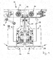
Figur 1- eine Vorderansicht einer Ausführungsform einer Finishvorrichtung;
- Figur 2
- eine perspektivische Darstellung einer in
Figur 1 - Figur 3
- eine der
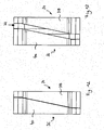
Figur 2 entsprechende Darstellung, wobei die Andrück- und Führungselemente eine zweite Lage einnehmen; - Figur 4
- eine Vorderansicht der Baugruppe gemäß
Figuren 2 und3 , wobei die Andrück- und Führungselemente die erste Lage einnehmen; Figur 5- eine der
Figur 4 entsprechende Darstellung, wobei die Andrück- und Führungselemente die zweite Lage einnehmen; - Figur 6
- eine Draufsicht der Baugruppe gemäß
Figuren 2 und3 , wobei die Andrück- und Führungselemente die erste Lage einnehmen; Figur 7- eine der
Figur 6 entsprechende Darstellung, wobei die Andrück- und Führungselemente die zweite Lage einnehmen; - Figur 8
- eine Vorderansicht einer in
Figur 1 - Figur 9
- eine der
Figur 8 entsprechende Darstellung, wobei die Andrück- und Führungselemente eine zweite Lage einnehmen; - Figur 10
- einen Längsschnitt der Baugruppe gemäß
Figur 8 ; - Figur 11
- einen Längsschnitt der Baugruppe gemäß
Figur 9 ; Figur 12- eine Vorderansicht von Andrückelementen, die eine erste Lage einnehmen;
- Figur 13
- eine der
Figur 12 entsprechende Darstellung, wobei die Andrückelemente eine zweite Lage einnehmen; Figur 14- eine Rückansicht der Andrückelemente gemäß
Figur 12 , wobei die Andrückelemente die erste Lage einnehmen; und - Figur 15
- eine der
Figur 14 entsprechende Darstellung, wobei die Andrückelemente die zweite Lage einnehmen.
- FIG. 1
- a front view of an embodiment of a finishing device;
- FIG. 2
- a perspective view of an in
FIG. 1 denoted by II assembly whose pressing and guiding elements occupy a first position; - FIG. 3
- one of the
FIG. 2 corresponding representation, wherein the pressing and guiding elements occupy a second position; - FIG. 4
- a front view of the assembly according to
Figures 2 and3 wherein the pressing and guiding elements occupy the first position; - FIG. 5
- one of the
FIG. 4 corresponding representation, wherein the pressing and guiding elements occupy the second position; - FIG. 6
- a plan view of the assembly according to
Figures 2 and3 wherein the pressing and guiding elements occupy the first position; - FIG. 7
- one of the
FIG. 6 corresponding representation, wherein the pressing and guiding elements occupy the second position; - FIG. 8
- a front view of an in
FIG. 1 VIII designated assembly, wherein the pressing and guiding elements occupy a first position; - FIG. 9
- one of the
FIG. 8 corresponding representation, wherein the pressing and guiding elements occupy a second position; - FIG. 10
- a longitudinal section of the assembly according to
FIG. 8 ; - FIG. 11
- a longitudinal section of the assembly according to
FIG. 9 ; - FIG. 12
- a front view of pressing elements, which occupy a first position;
- FIG. 13
- one of the
FIG. 12 corresponding representation, wherein the pressing elements occupy a second position; - FIG. 14
- a rear view of the pressing elements according to
FIG. 12 , wherein the pressing elements occupy the first position; and - FIG. 15
- one of the
FIG. 14 corresponding representation, wherein the pressing elements occupy the second position.
Eine Ausführungsform einer Finishvorrichtung ist in der Zeichnung insgesamt mit dem Bezugszeichen 10 bezeichnet. Die Finishvorrichtung 10 umfasst einen ersten Schwenkarm 12, welcher um eine erste Schwenkachse 14 verschwenkbar ist. Zum Verschwenken des Schwenkarms 12 um die Schwenkachse 14 ist ein Schwenkantrieb 16 vorgesehen.An embodiment of a finishing device is indicated generally by the reference numeral 10 in the drawing. The finishing device 10 comprises a
Die Finishvorrichtung 10 weist einen zweiten Schwenkarm 18 auf, welcher um eine zweite Schwenkachse 20 verschwenkbar ist. Die Schwenkarme 12 und 18 sind mittels eines Zwischengetriebes 22, beispielsweise in Form eines Kopplungsglieds, bewegungsgekoppelt, sodass eine Schwenkbewegung des ersten Schwenkarms in einer bestimmten Schwenkrichtung um die Schwenkachse 14 in eine hierzu entgegengesetzt gerichtete Schwenkbewegung des Schwenkarms des zweiten Schwenkarms 18 um die zweite Schwenkachse 20 übertragen wird.The finishing device 10 has a
Die Schwenkarme 12 und 18 dienen jeweils zur Anordnung einer nachfolgend im Detail beschriebenen Andrückeinrichtung 24.The
Optional dienen die Schwenkarme 12 und 18 auch zur Befestigung jeweils einer Finishbandführung 26 zur Führung eines Finishbands 28.Optionally, the
Das Finishband 28 wird mittels einer ersten Führungseinrichtung 26 einer ersten Andrückeinrichtung 24 zugeführt, im Bereich einer beispielsweise an den Schwenkarmen 12 und/oder 18 angeordneten Umlenkeinrichtung 29 umgelenkt und von dort einer zweiten Andrückeinrichtung 24 und schließlich einer zweiten Finishbandführung 26 zugeführt.The finishing
Vorzugsweise sind die erste Andrückeinrichtung 24 und die zweite Andrückeinrichtung 24 miteinander identisch, sodass eine hohe Anzahl von Gleichteilen verwendet werden kann.Preferably, the first
In
Der Andrückelementhalter 32 dient zum Halten eines ersten Andrückelements 34 und eines zweiten Andrückelements 36. Das Andrückelement 34 weist einen ersten, gekrümmten Andrückflächenabschnitt 38 auf. Das zweite Andrückelement weist einen zweiten, gekrümmten Andrückflächenabschnitt 40 auf. Die Andrückflächenabschnitte 38 und 40 bilden gemeinsam eine gekrümmte Andrückfläche 42.The
Beide Andrückflächenabschnitte 38 und 40 erstrecken sich zwischen einem Finishband-Einführende 44 und einem Finishband-Ausführende 46.Both
Im Bereich des Finishband-Einführendes 44 und im Bereich des Finishband-Ausführendes 46 sind rollenförmige Verschleißelemente 48, 50 vorgesehen, auf welchen die Rückseite eines (nicht dargestellten) Finishbands abgleitet. Jedes der Andrückelemente 34, 36 weist jeweils ein kurzes Verschleißelement 48 und ein langes Verschleißelement 50 auf.In the area of the finishing
Eine Verlaufsrichtung des Finishbands ist in
Die Führungseinrichtungen 54, 56 sind jeweils zweiteilig und weisen jeweils ein erstes Führungselement 58 und ein zweites Führungselement 60 auf. Das erste Führungselement 58 weist einen insbesondere gekrümmten und insbesondere dem zweiten Führungselement 60 zugewandten ersten Führungsflächenabschnitt 62 auf. Das zweite Führungselement 60 weist einen insbesondere gekrümmten und insbesondere dem ersten Führungselement 58 zugewandten zweiten Führungsflächenabschnitt 64 auf.The
Die Führungsflächenabschnitte 62 und 64 bilden gemeinsam eine mehrteilige Führungsfläche 66.The
Die ersten Führungselemente 58 einer Führungseinrichtung 54, 56 sind jeweils mittels eines Halters 68 mit dem ersten Andrückelement 34 verbunden. Die zweiten Führungselemente 60 sind jeweils mittels eines Halters 70 mit dem zweiten Andrückelement 36 verbunden.The
Der Abstand der Andrückelemente 34 und 36 ist in einer mit dem Bezugszeichen 72 bezeichneten Breitenrichtung des Finishbands 28, welche quer, insbesondere senkrecht, zu der Verlaufsrichtung 52 des Finishbands 28 verläuft, einstellbar.The distance of the
In
In dieser Relativlage der Andrückelemente 34 und 36 liegt auch der kleinstmögliche Abstand zwischen den Führungsflächenabschnitten 62 und 64 der Führungselemente 58 und 60 an.In this relative position of the
Mittels einer nachfolgend detaillierter beschriebenen Einstelleinrichtung ist der Abstand der Andrückelemente 34 und 36 in Breitenrichtung 72 des Finishbands 28 einstellbar.By means of a setting device described in more detail below, the distance between the
Der Spalt 73 erstreckt sich vorzugsweise zwischen dem Finishband-Einführende 44 und dem Finishband-Ausführende 46.The
In
Die Begrenzungen 74, 76 sind zueinander komplementär, sodass sie in einer Lage, in welcher die Andrückflächenabschnitte 38 und 40 einen kleinstmöglichen Abstand zueinander haben, aneinander anliegen und kein Spalt 73 zwischen den Andrückelementen 34 und 36 entsteht. In dieser Relativlage der Andrückelemente 38 und 40 entsteht eine durchgängige Andrückfläche 42 mit einer parallel zur Breitenrichtung 72 gemessenen, ersten Führungsbreite 78.The
Bei Beabstandung der Führungselemente 34 und 36 (vergleiche
Die Begrenzungen 74 und 76 weisen einen relativ zu der Verlaufsrichtung 52 des Finishbands 28 gemessenen Neigungswinkel 81 auf. Dieser Neigungswinkel 81 ist abgestimmt auf die Abmessungen der Andrückflächenabschnitte 38 und 40 so klein, dass sich die Andrückflächenabschnitte 38 und 40 beider Andrückelemente 34 und 36 jeweils zwischen dem Finishband-Einführende 44 und dem Finishband-Ausführende 46 erstrecken. Der Neigungswinkel 81 ist jedoch so groß, dass ein zwischen dem Finishband-Einführende 44 und dem Finishband-Ausführende 46 angeordneter Abschnitt eines Finishbands 28 entlang der gesamten Führungsbreite 80 gegen ein zu bearbeitendes Werkstück andrückbar ist. Dies bedeutet, dass sich die Andrückflächenabschnitte 38 und 40 in Verlaufsrichtung 52 des Finishbands 28 gesehen zumindest anteilig überlappen.The
Bei einem im Prinzip denkbaren, zu der Verlaufsrichtung 52 parallelen Verlauf der Begrenzungen 74 und 76 der Andrückflächenabschnitte 38 und 40 entstünde ein parallel zu der Verlaufsrichtung 52 verlaufender Spalt 73, entlang welchem ein Finishband 28 in Breitenrichtung 72 gesehen nicht gegen ein zu bearbeitendes Werkstück andrückbar wäre.In a conceivable, in principle, parallel to the
Für den Fall, dass, wie vorstehend beschrieben, die Andrückelemente 34 und 36 jeweils mit Führungselementen 58, 60 einer Führungseinrichtung 54, 56 verbunden sind, liegt eine minimale Führungsbreite 82 (vergleiche
In entsprechender Weise korrespondiert eine vergrößerte Führungsbreite 84 (vergleiche
In den
Der Aufbau der Einstelleinrichtung 86 wird nachfolgend unter Bezugnahme auf
Die ersten Wirkabschnitte 94 des Einstellelements 96 wirken mit zweiten Wirkabschnitten 98 der Andrückelemente 34 und 36 zusammen (vergleiche
Die ersten Wirkabschnitte 96 des Einstellelements 92 weisen einen festen Abstand relativ zueinander auf. Aus diesem Grund geht eine Verlagerung des Einstellelements 92 aus der in
Die Baugruppe 90 wirkt über eine Gewindepaarung 102 mit einem Betätigungselement 104 zusammen. Das Betätigungselement 104 weist einen Betätigungsabschnitt 106 (beispielsweise eine Innensechskantfläche) zum Eingriff eines handbetätigbaren oder motorisch betätigbaren Werkzeugs auf. Ferner umfasst das Betätigungselement 104 eine Lagerung 108, mittels welcher das Betätigungselement 104 drehbar an dem Andrückelementhalter 32 gelagert ist. Eine Verdrehung des Betätigungselements 104 geht mit einer Verschiebung der Baugruppe 90 längs der Einstellachse 88 einher, ohne dass sich die Position des Betätigungselements 104 längs der Einstellachse 88 ändert.The assembly 90 cooperates via a pair of
Um die Relativposition der Andrückelemente 34 und 36 in einfacher Weise erfassen zu können, ist die Baugruppe 90 mit einem Referenzelement 110 (vergleiche
Zur Verbesserung der Genauigkeit der Relativpositionen der Andrückelemente 34 und 36 ist eine insgesamt mit dem Bezugszeichen 114 bezeichnete Führungseinrichtung (vergleiche
Im Prinzip ist es denkbar, dass die Einstelleinrichtung 86 und/oder die Führungseinrichtung 114 selbsthemmend sind, sodass eine nachfolgend beschriebene Befestigungseinrichtung zur Befestigung der Andrückelemente 34, 36 an dem Andrückelementhalter 32 nicht erforderlich ist. Für einen besonders stabilen Aufbau ist es jedoch vorteilhaft, wenn eine solche Befestigungseinrichtung, nachfolgend insgesamt mit dem Bezugszeichen 118 bezeichnet, vorgesehen ist.In principle, it is conceivable that the adjusting
Die Befestigungseinrichtung 118 umfasst in vorteilhafter Weise zwei Spannelemente 120, 122, mittels welchen die Andrückelemente 34, 36 in einem sich parallel zu der Verlaufsrichtung 52 des Finishbands 28 erstreckenden Zwischenraum einspannbar sind. Die Spannelemente 120, 122 sind jeweils über eine Schraubverbindung 124, 126 mit dem Andrückelementhalter 32 verspannbar.The
Zumindest eines der Spannelemente 120, 122 weist eine Keilfläche 128 auf, welche mit einer entsprechenden Keilfläche eines Keilelements 130 zusammenwirkt, das als Teil einer Schraubverbindung 124 und/oder 126 in Richtung auf den Träger 30 bewegbar ist. Auf diese Weise werden die Andrückelemente 34, 36 gegen eine Anlagefläche 132 des Andrückelementhalters 32 gedrückt und gleichzeitig in einer zu der Anlagefläche 132 parallelen Richtung zwischen den Spannelementen 120 und 122 eingespannt.At least one of the clamping
Zur Einstellung des Abstands der Andrückelemente 34 und 36 wird die Befestigungseinrichtung 118 unter Lösung der Schraubverbindungen 124, 126 gelockert, sodass die Andrückelemente 34, 36 parallel zu der Anlagefläche 132 und quer zu der Verlaufsrichtung 52 des Finishbands bewegbar sind und in ihrem Abstand mittels der Einstelleinrichtung 86 einstellbar sind. Ist der gewünschte Abstand erreicht, können die Andrückelemente 34, 36 wieder unter Betätigung der Schraubverbindungen 124, 126 fixiert werden.To adjust the distance of the
Zur Verbindung des mit dem Schwenkarm 12 oder 18 verbundenen Trägers 30 einer Andrückeinrichtung 24 und des Andrückelementhalters 32 ist es denkbar, dass eine starre Verbindung vorgesehen ist. Bevorzugt ist es jedoch, wenn eine nachfolgend beschriebene, federelastische Verbindungseinrichtung 134 zur Verbindung des Trägers 30 (oder eines Schwenkarms 12, 18) und des Andrückelementhalters 32 vorgesehen ist.In order to connect the
Die Verbindungseinrichtung 134 umfasst eine bezogen auf die Andrückfläche 42 in etwa zentral angeordnete Verbindungsschraube 136, welche beispielsweise an dem Andrückelementhalter 32 gelagert und mit dem Träger 30 verschraubt ist. Zur Erzeugung einer Kippbeweglichkeit des Andrückelementhalters 32 relativ zu dem Träger 30 ist ein Einspannabschnitt 138 des Andrückelementhalters 32 zwischen Federscheiben 140 oder einem Paket von Federscheiben 140 und einer Kugelkalotte 142 eingespannt. Die Kugelkalotte 142 wirkt mit einer an dem Träger 30 gelagerten Kugelpfanne 144 zusammen. Um eine Drehbewegung des Andrückelementhalters 32 um eine Achse der Verbindungsschraube 136 herum zu begrenzen, ist der Andrückelementhalter 32 seitlich zwischen Blattfedern 146 eingespannt (vergleiche
Die Verbindungseinrichtung 134 umfasst ferner elastische Stoßdämpfer 148, welche beispielsweise in Form von Elastomerpuffern ausgebildet sind.The connecting
Die Stoßdämpfer 148 sind relativ zu der zentralen Lagerung beanstandet angeordnet.The
Eine weitere verbesserte Verbindung zwischen dem Träger 30 und dem Andrückelementhalter 32 ergibt sich, wenn möglichst weit außen angeordnete und zwischen Träger 30 und Andrückelementhalter 32 wirkende federelastische Abstützeinrichtungen 150 vorgesehen sind. Diese umfassen beispielsweise Federn 152, welche jeweils zwischen Anschlägen 154, 156 fixiert sind. Jeweils einer der Anschläge 154, 156 ist mit jeweils einem der Träger 30 beziehungsweise Andrückelementhalter 32 verbunden. Die Anschläge 154 und 156 können beispielsweise in Form von Schrauben ausgebildet sein, deren Schaft von einem jeweils freien Ende 158 der Feder 152 umgriffen sind.A further improved connection between the
Claims (14)
- A finishing device (10), comprising a pressure device (24) having a curved pressure surface (42), along which a finishing belt (28) may be pressed against a work piece to be finished between the lead-in end (44) and the lead-out end (46) of the finishing belt, is characterized in that the pressure device (24) has a first pressure element (34) having a first pressure-surface segment (38) and a second pressure element (36) having a second pressure-surface segment (40), and in that an adjustment device (86) is provided for adjusting the distance between the pressure elements (34, 36) in the width direction (72) of the finishing belt (28).
- The finishing device (10) as recited in Claim 1, characterized in that the pressure-surface segments (38, 40) at least partially overlap viewed in the extension direction (52) of the finishing belt (28).
- The finishing device (10) as recited in any of the preceding claims, characterized in that the boundaries (74, 76) of the pressure-surface segments (38, 40) facing each other are designed to complement each other.
- The finishing device (10) as recited in any of the preceding claims, characterized in that the boundaries (74, 76) of the pressure-surface segments (38, 40) extend in a direction that is at an angle with respect to the extension direction (52) of the finishing belt (28).
- The finishing device (10) as recited in any of the preceding claims, characterized in that at least one pressure-surface segment (38, 40), preferably both pressure-surface segments (38, 40), extends/extend between the lead-in end (44) and the lead-out end (46) of the finishing belt.
- The finishing device (10) as recited in any of the preceding claim, characterized in that the position of only one of the pressure elements (34, 36) may be adjusted using the adjustment device (86).
- The finishing device (10) as recited in any of Claims 1 to 5, characterized in that the positions of both pressure elements (34, 36) may be altered using the adjustment device (86).
- The finishing device (10) as recited in any of the preceding claims, characterized in that a guide device (114) is provided for guiding the pressure elements (34, 36) in the width direction (72) of the finishing belt (28) .
- The finishing device (10) as recited in any of the preceding claims, characterized in that the adjustment device (86) includes a movable adjusting element (92), which via first active segments (94) cooperates with associated second active segments (98) of the pressure elements (34, 36).
- The finishing device (10) as recited in Claim 9, characterized in that the first active segments (94) or the second active segments (98) are configured as sliding blocks (96), and in that the second active segments (98) or the first active segments (94) are configured as block guides (100) for guiding the sliding blocks (96).
- The finishing device (10) as recited in any of the preceding claims, characterized in that a pressure-element holder (32) is provided for holding the pressure elements (34, 36), and in that an attachment device (118) is provided for detachably attaching the pressure elements (34, 36) on the pressure-element holder (32).
- The finishing device (10) as recited in Claim 11, whereby a pivot arm (12, 18) is provided, which is able to pivot the pressure device (24) in the direction of a work piece and then in the reverse direction, characterized in that the pressure-element holder (32) is connected by a spring-elastic connecting device (134) to the pivot arm (12, 18) or to a support (30) that is connected to the pivot arm.
- The finishing device (10) as recited in any of the preceding claims, characterized in that a guide device (54, 56), which is arranged upstream of the lead-in end (44) and/or downstream of the lead-out end (46) of the finishing belt viewed in the extension direction (52) of the finishing belt (28), is provided with a guide surface (66) for guiding the finishing belt (28), whereby the guide device (54, 56) has a first guide element (58) having a first guide-surface segment (62) and a second guide element (60) having second guide-surface segment (64), and in that an adjustment device (86) is provided to adjust the distance between the guide elements (58, 60) in the width direction (72) of the finishing belt (28).
- The finishing device (10) as recited in Claim 13, characterized in that the first pressure element (34) and the first guide element (58) are immovably connected to each other, in that the second pressure element (36) and the second guide element (60) are immovably connected to each other, and in that a common adjustment device (86) is provided for adjusting the distance between the pressure elements (34, 36) and for adjusting the distance between the guide elements (58, 60).
Priority Applications (1)
| Application Number | Priority Date | Filing Date | Title |
|---|---|---|---|
| EP20120172206 EP2674248B1 (en) | 2012-06-15 | 2012-06-15 | Finishing device |
Applications Claiming Priority (1)
| Application Number | Priority Date | Filing Date | Title |
|---|---|---|---|
| EP20120172206 EP2674248B1 (en) | 2012-06-15 | 2012-06-15 | Finishing device |
Publications (2)
| Publication Number | Publication Date |
|---|---|
| EP2674248A1 EP2674248A1 (en) | 2013-12-18 |
| EP2674248B1 true EP2674248B1 (en) | 2014-09-17 |
Family
ID=46395470
Family Applications (1)
| Application Number | Title | Priority Date | Filing Date |
|---|---|---|---|
| EP20120172206 Not-in-force EP2674248B1 (en) | 2012-06-15 | 2012-06-15 | Finishing device |
Country Status (1)
| Country | Link |
|---|---|
| EP (1) | EP2674248B1 (en) |
Families Citing this family (2)
| Publication number | Priority date | Publication date | Assignee | Title |
|---|---|---|---|---|
| DE102014208319B4 (en) * | 2014-05-05 | 2021-05-06 | Supfina Grieshaber Gmbh & Co. Kg | Tape finishing device and method of operating a tape finishing device |
| BR112020011800A2 (en) * | 2017-12-14 | 2020-11-17 | Thielenhaus Technologies Gmbh | pressure shoe |
Family Cites Families (4)
| Publication number | Priority date | Publication date | Assignee | Title |
|---|---|---|---|---|
| US5437125A (en) * | 1992-03-16 | 1995-08-01 | Barton, Ii; Kenneth A. | Surface polishing assembly |
| US5311704A (en) * | 1992-05-20 | 1994-05-17 | Barton Ii Kenneth A | Method and apparatus for correcting diametrical taper on a workpiece |
| FR2764224B1 (en) * | 1997-06-06 | 1999-08-27 | Procede Machines Speciales Spm | MACHINING MACHINE BY ABRASIVE BELT FOR CYLINDRICAL SHAFT SEATS |
| FR2808463B1 (en) * | 2000-05-04 | 2002-09-13 | Procedes Et Machines Speciales | ABRASIVE TAPE MACHINE FOR CYLINDRICAL DOORS ON PARTS |
-
2012
- 2012-06-15 EP EP20120172206 patent/EP2674248B1/en not_active Not-in-force
Also Published As
| Publication number | Publication date |
|---|---|
| EP2674248A1 (en) | 2013-12-18 |
Similar Documents
| Publication | Publication Date | Title |
|---|---|---|
| EP2540438B1 (en) | Stationary support | |
| EP2505303B1 (en) | Stationary support | |
| EP2505302A1 (en) | Stationary support | |
| EP2097199B1 (en) | System pendulum apparatus and method | |
| DE2255275B1 (en) | Device for longitudinal cutting of material webs, in particular paper webs | |
| EP2674248B1 (en) | Finishing device | |
| DE2738612C2 (en) | Device for a machine for erosive spark machining | |
| DE3925717A1 (en) | DEVICE ON MACHINE VICE FOR CENTRICALLY CLAMPING WORKPIECES | |
| DE3010634A1 (en) | HOLDING DEVICE FOR THE STATIONAL THREADED JAW OF A THREAD ROLLING MACHINE | |
| DE2831482C3 (en) | Device for controlling the axial movement of the workpiece headstock of an edge grinding machine for the production of so-called Kaiser roof fecettes on lenses | |
| DE102011078735B4 (en) | finish device | |
| DE202009004809U1 (en) | Pipe grinding machine with adjustable side guide of the sanding belt | |
| AT516434B1 (en) | Finishing unit with position adjustable copying device | |
| DE9312116U1 (en) | Tangential roller head | |
| EP3072635B1 (en) | Device for supporting a workpiece to be machined | |
| EP0416167B1 (en) | Apparatus for spiral sharpening | |
| EP0305559A1 (en) | Pressure applying device for continuous edging, postforming or sheathing machines | |
| DE102012019307A1 (en) | Linear guide device for positioning applications, has two guide rails, which extend along x-axis of Cartesian coordinate system, where carriage base of guide carriage is linearly displaced on former guide rail | |
| DE2842014C3 (en) | Device for correcting the lead screw pitch errors on a machine tool | |
| EP2399706A1 (en) | Finishing device for finishing the surfaces of workpieces | |
| DE102009025784A1 (en) | Pipe drilling machine, has clamping roller rotated around clamping roller axis and movably supported at clamping roller frame at side such that roller is aligned along running direction of drilling band at different angular positions | |
| DE2614107A1 (en) | Hole cutter fine setting guide bush holder - adjusts angled bushing co-ordinating with four angle headed setting blocks | |
| EP3394651B1 (en) | Alignment device for an end of an optical fibre | |
| EP2976182B1 (en) | Device for centring workpieces | |
| DE2206838C3 (en) | Contact device for supplying electrical current to an electrode. an electric furnace |
Legal Events
| Date | Code | Title | Description |
|---|---|---|---|
| PUAI | Public reference made under article 153(3) epc to a published international application that has entered the european phase |
Free format text: ORIGINAL CODE: 0009012 |
|
| AK | Designated contracting states |
Kind code of ref document: A1 Designated state(s): AL AT BE BG CH CY CZ DE DK EE ES FI FR GB GR HR HU IE IS IT LI LT LU LV MC MK MT NL NO PL PT RO RS SE SI SK SM TR |
|
| AX | Request for extension of the european patent |
Extension state: BA ME |
|
| 17P | Request for examination filed |
Effective date: 20140227 |
|
| RBV | Designated contracting states (corrected) |
Designated state(s): AL AT BE BG CH CY CZ DE DK EE ES FI FR GB GR HR HU IE IS IT LI LT LU LV MC MK MT NL NO PL PT RO RS SE SI SK SM TR |
|
| GRAP | Despatch of communication of intention to grant a patent |
Free format text: ORIGINAL CODE: EPIDOSNIGR1 |
|
| RIC1 | Information provided on ipc code assigned before grant |
Ipc: B24B 21/00 20060101ALI20140331BHEP Ipc: B24B 19/12 20060101ALI20140331BHEP Ipc: B24B 5/42 20060101AFI20140331BHEP |
|
| INTG | Intention to grant announced |
Effective date: 20140415 |
|
| GRAS | Grant fee paid |
Free format text: ORIGINAL CODE: EPIDOSNIGR3 |
|
| GRAA | (expected) grant |
Free format text: ORIGINAL CODE: 0009210 |
|
| AK | Designated contracting states |
Kind code of ref document: B1 Designated state(s): AL AT BE BG CH CY CZ DE DK EE ES FI FR GB GR HR HU IE IS IT LI LT LU LV MC MK MT NL NO PL PT RO RS SE SI SK SM TR |
|
| REG | Reference to a national code |
Ref country code: GB Ref legal event code: FG4D Free format text: NOT ENGLISH |
|
| REG | Reference to a national code |
Ref country code: CH Ref legal event code: EP |
|
| REG | Reference to a national code |
Ref country code: IE Ref legal event code: FG4D Free format text: LANGUAGE OF EP DOCUMENT: GERMAN |
|
| REG | Reference to a national code |
Ref country code: AT Ref legal event code: REF Ref document number: 687456 Country of ref document: AT Kind code of ref document: T Effective date: 20141015 |
|
| REG | Reference to a national code |
Ref country code: DE Ref legal event code: R096 Ref document number: 502012001265 Country of ref document: DE Effective date: 20141030 |
|
| PG25 | Lapsed in a contracting state [announced via postgrant information from national office to epo] |
Ref country code: SE Free format text: LAPSE BECAUSE OF FAILURE TO SUBMIT A TRANSLATION OF THE DESCRIPTION OR TO PAY THE FEE WITHIN THE PRESCRIBED TIME-LIMIT Effective date: 20140917 Ref country code: NO Free format text: LAPSE BECAUSE OF FAILURE TO SUBMIT A TRANSLATION OF THE DESCRIPTION OR TO PAY THE FEE WITHIN THE PRESCRIBED TIME-LIMIT Effective date: 20141217 Ref country code: GR Free format text: LAPSE BECAUSE OF FAILURE TO SUBMIT A TRANSLATION OF THE DESCRIPTION OR TO PAY THE FEE WITHIN THE PRESCRIBED TIME-LIMIT Effective date: 20141218 Ref country code: LT Free format text: LAPSE BECAUSE OF FAILURE TO SUBMIT A TRANSLATION OF THE DESCRIPTION OR TO PAY THE FEE WITHIN THE PRESCRIBED TIME-LIMIT Effective date: 20140917 Ref country code: FI Free format text: LAPSE BECAUSE OF FAILURE TO SUBMIT A TRANSLATION OF THE DESCRIPTION OR TO PAY THE FEE WITHIN THE PRESCRIBED TIME-LIMIT Effective date: 20140917 |
|
| REG | Reference to a national code |
Ref country code: NL Ref legal event code: VDEP Effective date: 20140917 |
|
| REG | Reference to a national code |
Ref country code: LT Ref legal event code: MG4D |
|
| PG25 | Lapsed in a contracting state [announced via postgrant information from national office to epo] |
Ref country code: HR Free format text: LAPSE BECAUSE OF FAILURE TO SUBMIT A TRANSLATION OF THE DESCRIPTION OR TO PAY THE FEE WITHIN THE PRESCRIBED TIME-LIMIT Effective date: 20140917 Ref country code: CY Free format text: LAPSE BECAUSE OF FAILURE TO SUBMIT A TRANSLATION OF THE DESCRIPTION OR TO PAY THE FEE WITHIN THE PRESCRIBED TIME-LIMIT Effective date: 20140917 Ref country code: LV Free format text: LAPSE BECAUSE OF FAILURE TO SUBMIT A TRANSLATION OF THE DESCRIPTION OR TO PAY THE FEE WITHIN THE PRESCRIBED TIME-LIMIT Effective date: 20140917 Ref country code: RS Free format text: LAPSE BECAUSE OF FAILURE TO SUBMIT A TRANSLATION OF THE DESCRIPTION OR TO PAY THE FEE WITHIN THE PRESCRIBED TIME-LIMIT Effective date: 20140917 |
|
| PG25 | Lapsed in a contracting state [announced via postgrant information from national office to epo] |
Ref country code: NL Free format text: LAPSE BECAUSE OF FAILURE TO SUBMIT A TRANSLATION OF THE DESCRIPTION OR TO PAY THE FEE WITHIN THE PRESCRIBED TIME-LIMIT Effective date: 20140917 |
|
| PG25 | Lapsed in a contracting state [announced via postgrant information from national office to epo] |
Ref country code: ES Free format text: LAPSE BECAUSE OF FAILURE TO SUBMIT A TRANSLATION OF THE DESCRIPTION OR TO PAY THE FEE WITHIN THE PRESCRIBED TIME-LIMIT Effective date: 20140917 Ref country code: CZ Free format text: LAPSE BECAUSE OF FAILURE TO SUBMIT A TRANSLATION OF THE DESCRIPTION OR TO PAY THE FEE WITHIN THE PRESCRIBED TIME-LIMIT Effective date: 20140917 Ref country code: EE Free format text: LAPSE BECAUSE OF FAILURE TO SUBMIT A TRANSLATION OF THE DESCRIPTION OR TO PAY THE FEE WITHIN THE PRESCRIBED TIME-LIMIT Effective date: 20140917 Ref country code: RO Free format text: LAPSE BECAUSE OF FAILURE TO SUBMIT A TRANSLATION OF THE DESCRIPTION OR TO PAY THE FEE WITHIN THE PRESCRIBED TIME-LIMIT Effective date: 20140917 Ref country code: SK Free format text: LAPSE BECAUSE OF FAILURE TO SUBMIT A TRANSLATION OF THE DESCRIPTION OR TO PAY THE FEE WITHIN THE PRESCRIBED TIME-LIMIT Effective date: 20140917 Ref country code: IS Free format text: LAPSE BECAUSE OF FAILURE TO SUBMIT A TRANSLATION OF THE DESCRIPTION OR TO PAY THE FEE WITHIN THE PRESCRIBED TIME-LIMIT Effective date: 20150117 Ref country code: PT Free format text: LAPSE BECAUSE OF FAILURE TO SUBMIT A TRANSLATION OF THE DESCRIPTION OR TO PAY THE FEE WITHIN THE PRESCRIBED TIME-LIMIT Effective date: 20150119 |
|
| PG25 | Lapsed in a contracting state [announced via postgrant information from national office to epo] |
Ref country code: PL Free format text: LAPSE BECAUSE OF FAILURE TO SUBMIT A TRANSLATION OF THE DESCRIPTION OR TO PAY THE FEE WITHIN THE PRESCRIBED TIME-LIMIT Effective date: 20140917 |
|
| REG | Reference to a national code |
Ref country code: DE Ref legal event code: R097 Ref document number: 502012001265 Country of ref document: DE |
|
| PLBE | No opposition filed within time limit |
Free format text: ORIGINAL CODE: 0009261 |
|
| STAA | Information on the status of an ep patent application or granted ep patent |
Free format text: STATUS: NO OPPOSITION FILED WITHIN TIME LIMIT |
|
| PG25 | Lapsed in a contracting state [announced via postgrant information from national office to epo] |
Ref country code: DK Free format text: LAPSE BECAUSE OF FAILURE TO SUBMIT A TRANSLATION OF THE DESCRIPTION OR TO PAY THE FEE WITHIN THE PRESCRIBED TIME-LIMIT Effective date: 20140917 |
|
| 26N | No opposition filed |
Effective date: 20150618 |
|
| PG25 | Lapsed in a contracting state [announced via postgrant information from national office to epo] |
Ref country code: IT Free format text: LAPSE BECAUSE OF FAILURE TO SUBMIT A TRANSLATION OF THE DESCRIPTION OR TO PAY THE FEE WITHIN THE PRESCRIBED TIME-LIMIT Effective date: 20140917 |
|
| PG25 | Lapsed in a contracting state [announced via postgrant information from national office to epo] |
Ref country code: SI Free format text: LAPSE BECAUSE OF FAILURE TO SUBMIT A TRANSLATION OF THE DESCRIPTION OR TO PAY THE FEE WITHIN THE PRESCRIBED TIME-LIMIT Effective date: 20140917 |
|
| PG25 | Lapsed in a contracting state [announced via postgrant information from national office to epo] |
Ref country code: MC Free format text: LAPSE BECAUSE OF FAILURE TO SUBMIT A TRANSLATION OF THE DESCRIPTION OR TO PAY THE FEE WITHIN THE PRESCRIBED TIME-LIMIT Effective date: 20140917 |
|
| REG | Reference to a national code |
Ref country code: CH Ref legal event code: PL |
|
| PG25 | Lapsed in a contracting state [announced via postgrant information from national office to epo] |
Ref country code: LU Free format text: LAPSE BECAUSE OF FAILURE TO SUBMIT A TRANSLATION OF THE DESCRIPTION OR TO PAY THE FEE WITHIN THE PRESCRIBED TIME-LIMIT Effective date: 20150615 |
|
| REG | Reference to a national code |
Ref country code: IE Ref legal event code: MM4A |
|
| REG | Reference to a national code |
Ref country code: FR Ref legal event code: ST Effective date: 20160229 |
|
| PG25 | Lapsed in a contracting state [announced via postgrant information from national office to epo] |
Ref country code: LI Free format text: LAPSE BECAUSE OF NON-PAYMENT OF DUE FEES Effective date: 20150630 Ref country code: IE Free format text: LAPSE BECAUSE OF NON-PAYMENT OF DUE FEES Effective date: 20150615 Ref country code: CH Free format text: LAPSE BECAUSE OF NON-PAYMENT OF DUE FEES Effective date: 20150630 |
|
| PG25 | Lapsed in a contracting state [announced via postgrant information from national office to epo] |
Ref country code: FR Free format text: LAPSE BECAUSE OF NON-PAYMENT OF DUE FEES Effective date: 20150630 |
|
| PG25 | Lapsed in a contracting state [announced via postgrant information from national office to epo] |
Ref country code: MT Free format text: LAPSE BECAUSE OF FAILURE TO SUBMIT A TRANSLATION OF THE DESCRIPTION OR TO PAY THE FEE WITHIN THE PRESCRIBED TIME-LIMIT Effective date: 20140917 |
|
| GBPC | Gb: european patent ceased through non-payment of renewal fee |
Effective date: 20160615 |
|
| PG25 | Lapsed in a contracting state [announced via postgrant information from national office to epo] |
Ref country code: GB Free format text: LAPSE BECAUSE OF NON-PAYMENT OF DUE FEES Effective date: 20160615 Ref country code: SM Free format text: LAPSE BECAUSE OF FAILURE TO SUBMIT A TRANSLATION OF THE DESCRIPTION OR TO PAY THE FEE WITHIN THE PRESCRIBED TIME-LIMIT Effective date: 20140917 Ref country code: HU Free format text: LAPSE BECAUSE OF FAILURE TO SUBMIT A TRANSLATION OF THE DESCRIPTION OR TO PAY THE FEE WITHIN THE PRESCRIBED TIME-LIMIT; INVALID AB INITIO Effective date: 20120615 Ref country code: BG Free format text: LAPSE BECAUSE OF FAILURE TO SUBMIT A TRANSLATION OF THE DESCRIPTION OR TO PAY THE FEE WITHIN THE PRESCRIBED TIME-LIMIT Effective date: 20140917 |
|
| PG25 | Lapsed in a contracting state [announced via postgrant information from national office to epo] |
Ref country code: BE Free format text: LAPSE BECAUSE OF NON-PAYMENT OF DUE FEES Effective date: 20150630 |
|
| PG25 | Lapsed in a contracting state [announced via postgrant information from national office to epo] |
Ref country code: TR Free format text: LAPSE BECAUSE OF FAILURE TO SUBMIT A TRANSLATION OF THE DESCRIPTION OR TO PAY THE FEE WITHIN THE PRESCRIBED TIME-LIMIT Effective date: 20140917 |
|
| PG25 | Lapsed in a contracting state [announced via postgrant information from national office to epo] |
Ref country code: MK Free format text: LAPSE BECAUSE OF FAILURE TO SUBMIT A TRANSLATION OF THE DESCRIPTION OR TO PAY THE FEE WITHIN THE PRESCRIBED TIME-LIMIT Effective date: 20140917 |
|
| REG | Reference to a national code |
Ref country code: AT Ref legal event code: MM01 Ref document number: 687456 Country of ref document: AT Kind code of ref document: T Effective date: 20170615 |
|
| PG25 | Lapsed in a contracting state [announced via postgrant information from national office to epo] |
Ref country code: AL Free format text: LAPSE BECAUSE OF FAILURE TO SUBMIT A TRANSLATION OF THE DESCRIPTION OR TO PAY THE FEE WITHIN THE PRESCRIBED TIME-LIMIT Effective date: 20140917 |
|
| PG25 | Lapsed in a contracting state [announced via postgrant information from national office to epo] |
Ref country code: AT Free format text: LAPSE BECAUSE OF NON-PAYMENT OF DUE FEES Effective date: 20170615 |
|
| PGFP | Annual fee paid to national office [announced via postgrant information from national office to epo] |
Ref country code: DE Payment date: 20210621 Year of fee payment: 10 |
|
| REG | Reference to a national code |
Ref country code: DE Ref legal event code: R119 Ref document number: 502012001265 Country of ref document: DE |
|
| PG25 | Lapsed in a contracting state [announced via postgrant information from national office to epo] |
Ref country code: DE Free format text: LAPSE BECAUSE OF NON-PAYMENT OF DUE FEES Effective date: 20230103 |
|
| P01 | Opt-out of the competence of the unified patent court (upc) registered |
Effective date: 20230621 |