EP2673793B1 - Bi-stable electromagnetic relay with x-drive motor - Google Patents
Bi-stable electromagnetic relay with x-drive motor Download PDFInfo
- Publication number
- EP2673793B1 EP2673793B1 EP12746573.0A EP12746573A EP2673793B1 EP 2673793 B1 EP2673793 B1 EP 2673793B1 EP 12746573 A EP12746573 A EP 12746573A EP 2673793 B1 EP2673793 B1 EP 2673793B1
- Authority
- EP
- European Patent Office
- Prior art keywords
- assembly
- core
- contact
- axis
- coil
- Prior art date
- Legal status (The legal status is an assumption and is not a legal conclusion. Google has not performed a legal analysis and makes no representation as to the accuracy of the status listed.)
- Active
Links
- 230000000712 assembly Effects 0.000 claims description 32
- 238000000429 assembly Methods 0.000 claims description 32
- 230000005291 magnetic effect Effects 0.000 claims description 31
- 238000013016 damping Methods 0.000 claims description 22
- 238000000034 method Methods 0.000 claims description 11
- 230000002708 enhancing effect Effects 0.000 claims description 6
- 230000005284 excitation Effects 0.000 description 8
- 230000005405 multipole Effects 0.000 description 8
- RYGMFSIKBFXOCR-UHFFFAOYSA-N Copper Chemical compound [Cu] RYGMFSIKBFXOCR-UHFFFAOYSA-N 0.000 description 6
- 229910052802 copper Inorganic materials 0.000 description 6
- 239000010949 copper Substances 0.000 description 6
- 230000008901 benefit Effects 0.000 description 4
- 230000005294 ferromagnetic effect Effects 0.000 description 4
- 239000004020 conductor Substances 0.000 description 3
- 230000005611 electricity Effects 0.000 description 3
- 230000037361 pathway Effects 0.000 description 3
- 230000008569 process Effects 0.000 description 3
- 238000004891 communication Methods 0.000 description 2
- 238000006073 displacement reaction Methods 0.000 description 2
- 238000010348 incorporation Methods 0.000 description 2
- 235000020061 kirsch Nutrition 0.000 description 2
- 230000002093 peripheral effect Effects 0.000 description 2
- 229920003023 plastic Polymers 0.000 description 2
- 239000004033 plastic Substances 0.000 description 2
- 230000009467 reduction Effects 0.000 description 2
- 230000001105 regulatory effect Effects 0.000 description 2
- 238000012546 transfer Methods 0.000 description 2
- 238000010276 construction Methods 0.000 description 1
- 230000008878 coupling Effects 0.000 description 1
- 238000010168 coupling process Methods 0.000 description 1
- 238000005859 coupling reaction Methods 0.000 description 1
- 238000013461 design Methods 0.000 description 1
- 230000000694 effects Effects 0.000 description 1
- 230000001747 exhibiting effect Effects 0.000 description 1
- 238000012986 modification Methods 0.000 description 1
- 230000004048 modification Effects 0.000 description 1
- 238000012360 testing method Methods 0.000 description 1
Images


Classifications
-
- H—ELECTRICITY
- H01—ELECTRIC ELEMENTS
- H01H—ELECTRIC SWITCHES; RELAYS; SELECTORS; EMERGENCY PROTECTIVE DEVICES
- H01H51/00—Electromagnetic relays
- H01H51/22—Polarised relays
-
- H—ELECTRICITY
- H01—ELECTRIC ELEMENTS
- H01H—ELECTRIC SWITCHES; RELAYS; SELECTORS; EMERGENCY PROTECTIVE DEVICES
- H01H51/00—Electromagnetic relays
- H01H51/22—Polarised relays
- H01H51/2272—Polarised relays comprising rockable armature, rocking movement around central axis parallel to the main plane of the armature
-
- H—ELECTRICITY
- H01—ELECTRIC ELEMENTS
- H01H—ELECTRIC SWITCHES; RELAYS; SELECTORS; EMERGENCY PROTECTIVE DEVICES
- H01H1/00—Contacts
- H01H1/50—Means for increasing contact pressure, preventing vibration of contacts, holding contacts together after engagement, or biasing contacts to the open position
- H01H1/54—Means for increasing contact pressure, preventing vibration of contacts, holding contacts together after engagement, or biasing contacts to the open position by magnetic force
-
- H—ELECTRICITY
- H01—ELECTRIC ELEMENTS
- H01H—ELECTRIC SWITCHES; RELAYS; SELECTORS; EMERGENCY PROTECTIVE DEVICES
- H01H51/00—Electromagnetic relays
- H01H51/22—Polarised relays
- H01H51/2263—Polarised relays comprising rotatable armature, rotating around central axis perpendicular to the main plane of the armature
-
- H—ELECTRICITY
- H01—ELECTRIC ELEMENTS
- H01H—ELECTRIC SWITCHES; RELAYS; SELECTORS; EMERGENCY PROTECTIVE DEVICES
- H01H1/00—Contacts
- H01H1/50—Means for increasing contact pressure, preventing vibration of contacts, holding contacts together after engagement, or biasing contacts to the open position
-
- H—ELECTRICITY
- H01—ELECTRIC ELEMENTS
- H01H—ELECTRIC SWITCHES; RELAYS; SELECTORS; EMERGENCY PROTECTIVE DEVICES
- H01H50/00—Details of electromagnetic relays
- H01H50/16—Magnetic circuit arrangements
- H01H50/18—Movable parts of magnetic circuits, e.g. armature
- H01H50/30—Mechanical arrangements for preventing or damping vibration or shock, e.g. by balancing of armature
- H01H50/305—Mechanical arrangements for preventing or damping vibration or shock, e.g. by balancing of armature damping vibration due to functional movement of armature
-
- H—ELECTRICITY
- H01—ELECTRIC ELEMENTS
- H01H—ELECTRIC SWITCHES; RELAYS; SELECTORS; EMERGENCY PROTECTIVE DEVICES
- H01H50/00—Details of electromagnetic relays
- H01H50/44—Magnetic coils or windings
-
- H—ELECTRICITY
- H01—ELECTRIC ELEMENTS
- H01H—ELECTRIC SWITCHES; RELAYS; SELECTORS; EMERGENCY PROTECTIVE DEVICES
- H01H50/00—Details of electromagnetic relays
- H01H50/54—Contact arrangements
-
- H—ELECTRICITY
- H01—ELECTRIC ELEMENTS
- H01H—ELECTRIC SWITCHES; RELAYS; SELECTORS; EMERGENCY PROTECTIVE DEVICES
- H01H50/00—Details of electromagnetic relays
- H01H50/64—Driving arrangements between movable part of magnetic circuit and contact
- H01H50/641—Driving arrangements between movable part of magnetic circuit and contact intermediate part performing a rectilinear movement
Definitions
- the disclosed invention generally relates to an electromagnetic relay assembly incorporating a rotatable coil-core assembly. More particularly, the disclosed invention relates to an electromagnetic relay assembly having a magnetically actuable coil assembly rotatable about an axis of rotation extending orthogonally relative to the coil assembly axis.
- an electromagnetic relay Generally, the function of an electromagnetic relay is to use a small amount of power in the electromagnet to move an armature that is able to switch a much larger amount of power.
- the relay designer may want the electromagnet to energize using 5 volts and 50 milliamps (250 milliwatts), while the armature can support 120 volts at 2 amps (240 watts).
- Relays are quite common in home appliances where there is an electronic control turning on (or off) some application device such as a motor or a light.
- Several exemplary electromagnetic relay assemblies reflective of the state of the art and disclosed in United States patents are briefly described hereinafter.
- United States Patent No. 6,046,660 ('660 Patent), which issued to Gruner, discloses a Latching Magnetic Relay assembly with a Linear Motor.
- the '660 Patent describes a latching magnetic relay capable of transferring currents of greater than 100 amps for use in regulating the transfer of electricity or in other applications requiring the switching of currents of greater than 100 amps.
- a relay motor assembly has an elongated coil bobbin with an axially extending cavity therein. An excitation coil is wound around the bobbin.
- a generally U shaped ferromagnetic frame has a core section disposed in and extending through the axially extending cavity in the elongated coil bobbin.
- An actuator assembly is magnetically coupled to the relay motor assembly.
- the actuator assembly is comprised of an actuator frame operatively coupled to a first and a second generally U-shaped ferromagnetic pole pieces, and a permanent magnet.
- a contact bridge made of a sheet of conductive material copper is operatively coupled to the actuator assembly.
- United States Patent No. 6,246,306 ('306 Patent), which issued to Gruner, discloses an Electromagnetic Relay with Pressure Spring.
- the '306 Patent teaches an electromagnetic relay having a motor assembly with a bobbin secured to a housing.
- a core is adjacently connected below the bobbin except for a core end, which extends from the bobbin.
- An armature end magnetically engages the core end when the coil is energized.
- An actuator engages the armature and a plurality of center contact spring assemblies.
- the center contact spring assembly is comprised of a center contact spring which is not pre bent and is ultrasonically welded onto a center contact terminal.
- a normally open spring is positioned relatively parallel to a center contact spring.
- the normally open spring is ultrasonically welded onto a normally open terminal to form a normally open outer contact spring assembly.
- a normally closed outer contact spring is vertically positioned with respect to the center contact spring so that the normally closed outer contact spring assembly is in contact with the center contact spring assembly, when the center contact spring is not being acted upon by the actuator.
- the normally closed spring is ultrasonically welded onto a normally closed terminal to form a normally closed assembly.
- a pressure spring pressures the center contact spring above the actuator when the actuator is not in use.
- the '478 Patent describes an electromagnetic relay having a motor assembly with a bobbin secured to a frame.
- a core is disposed within the bobbin except for a core end which extends from the bobbin.
- An armature end magnetically engages the core end when the coil is energized.
- An actuator engages the armature and a plurality of movable blade assemblies.
- the movable blade assembly is comprised of a movable blade ultrasonically welded onto a center contact terminal.
- a normally open blade is positioned relatively parallel to a movable blade.
- the normally open blade is ultrasonically welded onto a normally open terminal to form a normally open contact assembly.
- a normally closed contact assembly comprised of a third contact rivet and a normally closed terminal.
- a normally closed contact assembly is vertically positioned with respect to the movable blade so that the normally closed contact assembly is in contact with the movable blade assembly when the movable blade is not being acted upon by the actuator.
- United States Patent No. 6,320,485 discloses an Electromagnetic Relay Assembly with a Linear Motor.
- the '485 Patent describes an electromagnetic relay capable of transferring currents of greater than 100 amps for use in regulating the transfer of electricity or in other applications requiring the switching of currents of greater than 100 amps.
- a relay motor assembly has an elongated coil bobbin with an axially extending cavity therein. An excitation coil is wound around the bobbin.
- a generally U shaped ferromagnetic frame has a core section disposed in and extending through the axially extending cavity in the elongated coil bobbin.
- An actuator assembly is magnetically coupled to the relay motor assembly.
- the actuator assembly is comprised of an actuator frame operatively coupled to a first and a second generally U-shaped ferromagnetic pole pieces, and a permanent magnet.
- a contact bridge made of a sheet of conductive material copper is operatively coupled to the actuator assembly.
- '409 Patent discloses a Latching Magnetic Relay Assembly.
- the '409 Patent describes a latching magnetic relay assembly comprising a relay motor with a first coil bobbin having a first excitation coil wound therearound and a second coil bobbin having a second excitation coil wound therearound, both said first excitation coil and said second excitation coil being identical, said first excitation coil being electrically insulated from said second excitation coil; an actuator assembly magnetically coupled to both said relay motor, said actuator assembly having a first end and a second end; and one or two groups of contact bridge assemblies, each of said group of contact bridge assemblies comprising a contact bridge and a spring.
- the '877 Patent describes an electromagnetic relay including a pivotable armature and contact springs extending substantially in parallel thereto, the actuator for transmitting the armature movement to the contact springs is coupled to the armature with play. Thereby relative displacements between the actuator and the contact spring and the resultant frictional forces are prevented.
- the relay may be a bistable relay, where the coupling between armature and actuator with play furthermore means that in the central position of the armature no spring forces and no frictional forces caused by the actuator are applied thereto but only the magnetic actuating forces will act on the armature.
- Japanese Patent No. JP S57-166015 which issued to Omron Tateisi Electronics Co., discloses a polarised electromagnet device, where the device reduces power consumption by connecting both end sections of a pair of approximately quadrilateral armatures by two permanent magnets and arranging approximately H-shaped cores at the insides so that the axial cores of coils are directed in the directions of these permanent magnets. Cores are wound on the central section of the H-shaped core. The areas of one attracting sections are set to value larger than the areas of the other attracting sections in a pair of the approximately quadrilateral armatures.
- the armatures are disposed to the upper and lower sections of the core so that the attracting sections, which have each the same areas, are opposed.;
- the armatures are connected by the two permanent magnets at the outsides of both end sections of the core, and supported rotatably centering around axes rectangular to the axial cores of the coils.
- the magnets are magnetized in the same direction.
- the Schmelz, Duchemin, and certain of the Gruner disclosures were particularly relevant to the subject matter as described in U.S. Patent Nos. 7,659,800 (the'800 Patent) and 7,710,224 (the '224 Patent), which issued to Gruner et al.
- the '800 and '224 Patents describe electromagnetic relays essentially comprising a coil assembly, a rotor or bridge assembly, and a switch assembly.
- the coil assembly comprises a coil and a C-shaped core.
- the coil is wound round a coil axis extending through the core.
- the core comprises core termini parallel to the coil axis.
- the bridge assembly comprises a H-shaped bridge and an actuator.
- the bridge comprises medial, lateral, and transverse field pathways.
- the actuator extends laterally from the lateral field pathway.
- the core termini are coplanar with the axis of rotation and received intermediate the medial and lateral field pathways.
- the actuator is cooperable with the switch assembly.
- the coil creates a magnetic field directable through the bridge assembly via the core termini for imparting bridge rotation about the axis of rotation.
- the bridge rotation displaces the actuator for opening and closing the switch assembly.
- the Kirsch Patent No. 5,568,108 ; the Reger et al. Patent No. 6,046,661 ; the Nakagawa et al. Patent No. 6,426,689 ; the Schmelz Patent Nos. 6,661,319 and 6,788,176 and the Gruner et al. '800 and 224 patents teach or describe armature assemblies having an H-shaped portion pivotable about a pivot axis of rotation, which H-shaped portion comprises or is otherwise attached to an elongated actuator arm extending from the H-shaped portion.
- the prior art thus perceives a need for an electromagnetic relay that is resistant to magnetic tampering whereby the permanent magnets are fixed or anchored and the coil assembly itself rotates with minimized displacements so as to intensify the operative magnetic field otherwise inherent to the same size magnets.
- the present invention essentially provides an electromagnetic relay assembly for selectively enabling current to pass through switch termini, which relay comprises a rotatable electromagnetic coil assembly, first and second pairs of opposed permanent magnets, and a switch assembly.
- the rotatable coil assembly comprises a current-conductive coil, an axially extending coil core, and a rotatable coil housing.
- the coil is wound around the core, which core is collinear or parallel with the axis of the coil.
- the coil comprises electromagnet-driving termini, the core comprises opposed core termini, and the coil housing has a housing axis of rotation orthogonal to the coil axis.
- the first and second pairs of opposed permanent magnets are respectively and fixedly positioned adjacent the core termini such that the core termini are respectively displacable intermediate the pairs of magnets.
- the switch assembly comprises first and second linkage arms, and first and second spring arms.
- the linkage arms interconnect the core termini and spring arms.
- the spring arms each comprise opposed pairs of contacts and a switch terminal.
- the coil operates to create a magnetic field directable through the core for imparting coil housing rotation about the housing axis of rotation via attraction to the positioned/anchored permanent magnets.
- the core termini displace linkage arms, and the linkage arms actuate the spring arms intermediate an open switch assembly position and a closed switch assembly position, the latter of which enables current to pass through the switch assembly via the contacts and the switch termini.
- Certain peripheral features of the essential electromagnetic relay assembly include, for example, certain spring means for damping contact vibration intermediate the contacts when switching from the open position to the closed position.
- the spring arms each may preferably comprise first and second spaced spring sections cooperable with the linkage arms and laterally spaced from the contacts so as to maximize the damping effect when switching from the open to closed switch assembly positions.
- the preferred embodiment of the present invention concerns a so-called bi-stable electromagnetic relay (with X-drive motor) assembly 10 as generally illustrated and referenced in Figure Nos. 1, 2, 4, and 5.
- Assembly 10 is believed to teach the basic structural concepts supporting the present invention, which basic structural concepts may be applied to either single pole assemblies as generally depicted and supported by assembly 10, or multiple pole assemblies.
- an exemplary four-pole assembly 20 is generally illustrated and referenced in Figure Nos. 16-19.
- the electromagnetic relay assembly 10 essentially functions to selectively enable current to pass through switch termini 11.
- the electromagnetic relay assembly 10 preferably comprises an electromagnetic coil assembly 12, first and second pairs of opposed permanent magnets 13, and a switch assembly comprising various components, including first and second linkage arms 14 (comprising one or more L-shaped portion(s)), and first and second spring arms 15, which arms 15 are in electrical communication with, or otherwise (conductively) fastened extensions of the switch termini 11.
- the coil assembly 12 may preferably be thought to comprise a current-conductive coil 16 (with spool assembly 26), a coil core 17, and a coil housing 18 (comprising a coil lid 18(a) (outfitted with coil lid conductor(s) 25) and a coil base or coil box 18(b)).
- the coil 16 is wound around the core 17, which core 17 is collinear with a coil axis as at 100.
- the coil 16 comprises electromagnet-driving termini as at 19, and the core 17 comprises (linearly) opposed core termini as at 21.
- the coil housing 18 has a housing axis of rotation 101, which axis 101 extends orthogonally relative to the coil axis 100.
- the housing axis of rotation 101 extends through pin structures 22 formed in axial alignment on the coil lid 18(a) and the coil box 18(b) of the housing 18, which pin structures 22 are received in pin-receiving structures 23 formed in a bracket 27 and relay housing 24.
- the first and second pairs of opposed permanent magnets 13 are respectively and fixedly obliquely positioned (via housing anchor structures 28) adjacent the core termini 21 such that the core termini 21 are respectively displacable intermediate the respective pairs of magnets 13.
- the opposed pairs of permanent magnets 13 each comprise substantially planar opposed magnet faces 29, which faces 29 extend in intersecting planes 102 thereby exhibiting an X-shaped planar configuration as at 103 in Figure No. generally defining the boundaries of movement of the core termini 21.
- the core 17 has a thickness as at 104, and the magnets 13 are positioned (via anchor structures 28) accordingly so as to properly contact the core termini 21.
- the core 17 preferably comprises substantially planar opposed core faces as at 30 such that the core faces 30 and magnet faces 29 are similarly angled when contacting one another for maximizing contact surface area and enhancing current flow through the maximized contacting surface area intermediate the core 17 and permanent magnets 13.
- linkage arms 14 function to interconnect the core termini 21 and spring arms 15.
- the spring arms 15 each comprise (i.e. are in electrical communication with or otherwise conductively fastened to) opposed pairs of contacts 31 and a switch terminal as at 11.
- the opposed pairs of contacts 31 are juxtaposed adjacent one another such that when the switch assembly is in a closed position, the contacts 31 contact one another as generally depicted in Figure Nos. 5, 7, 11, and 19.
- the open switch assembly position is generally and comparatively depicted in Figure Nos. 4, 6, 10, and 18.
- the coil 16 when provided with current, functions to create a magnetic field as at 105, which magnetic field 15 is directable through the core 17 and cooperable with the magnets 13 (as generally pole aligned and depicted in Figure Nos. 8 and 9) for imparting coil housing (pivot type) rotation (as at 106) about the housing axis of rotation 101.
- the core termini 21 thus function to displace the linkage arms 14, which linkage arms 14, in turn actuate the spring arms 15 intermediate the open position and the closed position as previously referenced. The closed position enables current to pass through the switch assembly via the contacts 31 and the switch termini 11.
- the linkage arms of assembly 10 are preferably L-shaped from a top plan view and thus comprise a first link portion as at 32 and a second link portion as at 33.
- the linkage arms 14 comprise a first link portion as at 34 and a series of second link portions as at 35 (or a series of interconnected L-shaped structures).
- the second link portions 33 and 35 of each assembly 10/20 respectively extend toward one another orthogonal to the first link portions 32 and 34 of each assembly 10/20.
- the core termini 21 are connected to the first link portions 32 or 34 and the spring arms 15 extend substantially parallel to the second link portions 33 or 35 when in an open switch assembly position.
- the spring arms 15 are preferably parallel to one another whether in the open or closed switch assembly positions and each comprise opposed faces, the inner faces 40 of which face one another as generally depicted and referenced in Figure Nos. 10 and 11.
- the opposed inner faces 40 are magnetically attractive to one another (as generally referenced at 107) during a short circuit scenario, and thus the magnetically attractive faces 40 function to maintain the contacts 31 in the closed switch assembly position during a short circuit scenario.
- the present invention enables the manufacturer to form one type of contact-spring assembly, and use the same assembly twice as generally depicted and illustrated by spring arm(s) 15, termini 11, and contacts 31.
- the described contact-spring assembly is similar to existing assemblies insofar as the terminals 11 and spring arms 15 are preferably constructed from copper whereby the spring arm 15 is placed on top of the copper terminal and then riveted together via the contact buttons 31.
- the spring arms 15 By arranging the spring arms 15 so that faces 40 oppose one another, a resulting contact system allows for one input from a copper terminal, then splits the load through two springs and outputs the load again on the other copper terminal. Since the two springs (i.e. spring arms 15) are preferably identical in terms of their manufacturability, they will bear a very similar, if not identical, resistance. Furthermore, these two springs are running directly parallel to one another, resulting in the same magnetic fields generated around the spring arms 15.
- the spring arms 15 preferably comprise first and second spring portions or means for effecting bi-stability.
- the first spring portions or means are generally contemplated to be exemplified by resiliently bends in the arms 15 as generally depicted and referenced at 36.
- the first spring means are preferably relaxed when in an open switch assembly position and preferably actuated when in a closed switch assembly position, but not necessarily so. It is contemplated that the actuated first spring means may well function to dampen contact vibration intermediate the contacts 31 when switching from the open switch assembly position to the closed switch assembly position.
- the second spring portions or means are generally contemplated to be exemplified by resilient spring extensions as generally depicted and referenced at 37.
- the second spring portions or means 37 are preferably relaxed when in an open switch assembly position and preferably actuated when in a closed switch assembly position, but not necessarily so configured. It is contemplated that the actuated second spring means may well function to enhance damped contact vibration intermediate the contacts 31 when switching from the open switch assembly position to the closed switch assembly position.
- first spring means are preferably actuable adjacent the first link portions 32 or 34 and that the second spring means are preferably actuable adjacent the second link portions 33 or 35.
- the first and second spring means thus provide spaced damping means for each contact pair. It is contemplated that the spaced damping means may well function to further enhance damped contact vibration intermediate the contacts 31 when switching from the open switch assembly position to the closed switch assembly position.
- each contact pair is preferably positioned intermediate the spaced first and second damping means, which spaced damping means thus provide laterally opposed damping means relative to each contact pair for still further enhancing damped contact vibration intermediate the contacts 31 when switching from the open switch assembly position to the closed switch assembly position.
- the typical structural remedy is to include additional leaf or coil springs to buffer the bounce of the contacts.
- the present invention takes advantage of a simple stamping process which enables the incorporation of an integrated bounce reduction spring as exemplified by resilient bends 36 and resilient extensions 37, which structural features are spaced laterally relative to the contacts 31.
- the present design thus applies contact pressure both the left and right side of the contact, ensuring equal contact pressure and making sure that the contacts stay closed when the relay is operated.
- an electromagnetic relay assembly comprising a rotatable coil assembly, opposed pairs of attractive magnets, and a switch assembly.
- the coil assembly comprises a coil, a core, and certain core-rotating means as exemplified by the rotatable coil housing with peripheral, pivot type rotation-enabling structures.
- the core is preferably collinear with or parallel to the axis of the coil and comprises exposed and opposed core termini.
- the core-rotating means have an axis of rotation that extends orthogonally relative to the coil axis.
- the opposed pairs of attractive magnets are respectively and fixedly positioned adjacent the core termini such that the core termini are respectively displacable intermediate the magnet pairs.
- the coil function to create a magnetic field directable through the core into opposed magnets for imparting rotation about the axis of rotation.
- the core termini actuate the switch assembly intermediate an open position and a closed position, the latter of which positions enable current to pass through the switch assembly.
- the electromagnetic relay assemblies further comprise certain linkage means and opposed spring assemblies.
- the linkage means as exemplified by the linkage arms 14 and 14(a) interconnect the core termini and spring assemblies.
- the spring assemblies essentially function to dampen contact vibration when switching from the open position to the closed position.
- the spring assemblies preferably comprise first and second spring means, which means are preferably relaxed when in the open position and preferably actuated when in the closed position, but the reverse structural configuration, namely that the first and second spring means may be relaxed when in the closed position and actuated when in the open position are also viable alternatives.
- the first and second spring means are spaced from one another opposite the contacts for providing spaced, laterally opposed damping means for further enhancing damped contact vibration of the switch assembly when switching from the open to closed positions.
- the spring arms of the spring assemblies are preferably parallel to one another and comprise opposed arm faces as at 40.
- the opposed arm faces 40 are magnetically attractive to one another during a short circuit scenario, which magnetically attractive arm faces for maintaining the switch assembly in the closed position during the short circuit scenario.
- the attractive magnets comprise opposed magnet faces, which opposed magnet faces are substantially planar and extend in intersecting planes, and the core (termini) have substantially planar opposed core faces.
- the contacting core faces and magnet faces are similarly angled for maximizing contact surface area for further enhancing current flow through contacting surface area intermediate the core and magnet faces.
- the inventive concepts discussed support certain new methodologies and/or processes.
- the foregoing structure considerations support a method for switching an electromagnetic relay comprising the steps of outfitting a coil assembly with means for rotating the coil assembly about an axis of rotation orthogonal to coil assembly axis whereafter a magnetic field may be created via the coil assembly and directed through the coil assembly into opposed magnets for imparting rotation about the axis of rotation.
- the coil assembly is then rotated (or pivoted) about the axis of rotation, and the switch assembly is actuated intermediate open and closed positions via the rotating coil assembly.
- the method is believed to further comprise the step of damping contact vibration via opposed contact-spring assemblies when displacing the switch assembly from the open to closed position, which may involve the step of laterally spacing the damping means relative to contacts of the switch assembly before the step of damping contact vibration.
- Certain faces (as at 40) of the contact-spring assemblies may be opposed before the step of damping contact vibration such that the opposed faces are magnetically attractive to one another during a short circuit scenario for maintaining the switch assembly in the closed position during said scenario.
Landscapes
- Physics & Mathematics (AREA)
- Electromagnetism (AREA)
- Electromagnets (AREA)
- Magnetic Treatment Devices (AREA)
- Variable-Direction Aerials And Aerial Arrays (AREA)
- Control Of Stepping Motors (AREA)
- Vending Machines For Individual Products (AREA)
- Dental Tools And Instruments Or Auxiliary Dental Instruments (AREA)
Description
- This application claims the benefit of pending
U.S. Patent Application No. 12/931,820 - The disclosed invention generally relates to an electromagnetic relay assembly incorporating a rotatable coil-core assembly. More particularly, the disclosed invention relates to an electromagnetic relay assembly having a magnetically actuable coil assembly rotatable about an axis of rotation extending orthogonally relative to the coil assembly axis.
- Generally, the function of an electromagnetic relay is to use a small amount of power in the electromagnet to move an armature that is able to switch a much larger amount of power. By way of example, the relay designer may want the electromagnet to energize using 5 volts and 50 milliamps (250 milliwatts), while the armature can support 120 volts at 2 amps (240 watts). Relays are quite common in home appliances where there is an electronic control turning on (or off) some application device such as a motor or a light. Several exemplary electromagnetic relay assemblies reflective of the state of the art and disclosed in United States patents are briefly described hereinafter.
- United States Patent No.
6,046,660 ('660 Patent), which issued to Gruner, discloses a Latching Magnetic Relay assembly with a Linear Motor. The '660 Patent describes a latching magnetic relay capable of transferring currents of greater than 100 amps for use in regulating the transfer of electricity or in other applications requiring the switching of currents of greater than 100 amps. A relay motor assembly has an elongated coil bobbin with an axially extending cavity therein. An excitation coil is wound around the bobbin. A generally U shaped ferromagnetic frame has a core section disposed in and extending through the axially extending cavity in the elongated coil bobbin. - Two contact sections extend generally perpendicularly to the core section and rises above the motor assembly. An actuator assembly is magnetically coupled to the relay motor assembly. The actuator assembly is comprised of an actuator frame operatively coupled to a first and a second generally U-shaped ferromagnetic pole pieces, and a permanent magnet. A contact bridge made of a sheet of conductive material copper is operatively coupled to the actuator assembly.
- United States Patent No.
6,246,306 ('306 Patent), which issued to Gruner, discloses an Electromagnetic Relay with Pressure Spring. The '306 Patent teaches an electromagnetic relay having a motor assembly with a bobbin secured to a housing. A core is adjacently connected below the bobbin except for a core end, which extends from the bobbin. An armature end magnetically engages the core end when the coil is energized. An actuator engages the armature and a plurality of center contact spring assemblies. The center contact spring assembly is comprised of a center contact spring which is not pre bent and is ultrasonically welded onto a center contact terminal. - A normally open spring is positioned relatively parallel to a center contact spring. The normally open spring is ultrasonically welded onto a normally open terminal to form a normally open outer contact spring assembly. A normally closed outer contact spring is vertically positioned with respect to the center contact spring so that the normally closed outer contact spring assembly is in contact with the center contact spring assembly, when the center contact spring is not being acted upon by the actuator. The normally closed spring is ultrasonically welded onto a normally closed terminal to form a normally closed assembly. A pressure spring pressures the center contact spring above the actuator when the actuator is not in use.
- United States Patent No.
6,252,478 ('478 Patent), which issued to Gruner, discloses an Electromagnetic Relay. The '478 Patent describes an electromagnetic relay having a motor assembly with a bobbin secured to a frame. A core is disposed within the bobbin except for a core end which extends from the bobbin. An armature end magnetically engages the core end when the coil is energized. An actuator engages the armature and a plurality of movable blade assemblies. The movable blade assembly is comprised of a movable blade ultrasonically welded onto a center contact terminal. - A normally open blade is positioned relatively parallel to a movable blade. The normally open blade is ultrasonically welded onto a normally open terminal to form a normally open contact assembly. A normally closed contact assembly comprised of a third contact rivet and a normally closed terminal. A normally closed contact assembly is vertically positioned with respect to the movable blade so that the normally closed contact assembly is in contact with the movable blade assembly when the movable blade is not being acted upon by the actuator.
- United States Patent No.
6,320,485 ('485 Patent), which issued to Gruner, discloses an Electromagnetic Relay Assembly with a Linear Motor. The '485 Patent describes an electromagnetic relay capable of transferring currents of greater than 100 amps for use in regulating the transfer of electricity or in other applications requiring the switching of currents of greater than 100 amps. A relay motor assembly has an elongated coil bobbin with an axially extending cavity therein. An excitation coil is wound around the bobbin. A generally U shaped ferromagnetic frame has a core section disposed in and extending through the axially extending cavity in the elongated coil bobbin. - Two contact sections extend generally perpendicularly to the core section and rises above the motor assembly. An actuator assembly is magnetically coupled to the relay motor assembly. The actuator assembly is comprised of an actuator frame operatively coupled to a first and a second generally U-shaped ferromagnetic pole pieces, and a permanent magnet. A contact bridge made of a sheet of conductive material copper is operatively coupled to the actuator assembly.
- United States Patent No.
6,563,409 ('409 Patent), which issued to Gruner, discloses a Latching Magnetic Relay Assembly. The '409 Patent describes a latching magnetic relay assembly comprising a relay motor with a first coil bobbin having a first excitation coil wound therearound and a second coil bobbin having a second excitation coil wound therearound, both said first excitation coil and said second excitation coil being identical, said first excitation coil being electrically insulated from said second excitation coil; an actuator assembly magnetically coupled to both said relay motor, said actuator assembly having a first end and a second end; and one or two groups of contact bridge assemblies, each of said group of contact bridge assemblies comprising a contact bridge and a spring. - United States Patent No.
4,743,877 ('877 Patent), which issued to Oberndorfer et al., discloses an electromagnetic relay, according to the preamble ofclaim 1. - The '877 Patent describes an electromagnetic relay including a pivotable armature and contact springs extending substantially in parallel thereto, the actuator for transmitting the armature movement to the contact springs is coupled to the armature with play. Thereby relative displacements between the actuator and the contact spring and the resultant frictional forces are prevented. The relay may be a bistable relay, where the coupling between armature and actuator with play furthermore means that in the central position of the armature no spring forces and no frictional forces caused by the actuator are applied thereto but only the magnetic actuating forces will act on the armature.
- Japanese Patent No.
JP S57-166015 - Other patent disclosures of particular interest are
U.S. Patent Nos. 5,568,108 , which issued to Kirsch;5,910,759 ;5,994,987 ;6,020,801 ;6,025,766 , all of which issued to Passow;5,933,065 , which issued to Duchemin;6,046,661 , which issued to Reger et al.;6,292,075 , which issued to Connell et al.;6,426,689 , which issued to Nakagawa et al.;6,661,319 and6,788,176 , which issued to Schmelz;6,949,997 , which issued to Bergh et al.;6,940,375 , which issued to Sanada et al.; andU.S. Patent Application Publication No. 2006/0279384 , which was authored by Takayama et al. - The Schmelz, Duchemin, and certain of the Gruner disclosures were particularly relevant to the subject matter as described in
U.S. Patent Nos. 7,659,800 (the'800 Patent) and7,710,224 (the '224 Patent), which issued to Gruner et al. The '800 and '224 Patents describe electromagnetic relays essentially comprising a coil assembly, a rotor or bridge assembly, and a switch assembly. The coil assembly comprises a coil and a C-shaped core. The coil is wound round a coil axis extending through the core. The core comprises core termini parallel to the coil axis. The bridge assembly comprises a H-shaped bridge and an actuator.
The bridge comprises medial, lateral, and transverse field pathways. The actuator extends laterally from the lateral field pathway. The core termini are coplanar with the axis of rotation and received intermediate the medial and lateral field pathways. The actuator is cooperable with the switch assembly. The coil creates a magnetic field directable through the bridge assembly via the core termini for imparting bridge rotation about the axis of rotation. The bridge rotation displaces the actuator for opening and closing the switch assembly. - Notably, the
Kirsch Patent No. 5,568,108 ; the Reger et al. Patent No.6,046,661 ; theNakagawa et al. Patent No. 6,426,689 ; theSchmelz Patent Nos. 6,661,319 and6,788,176 and the Gruner et al. '800 and 224 patents teach or describe armature assemblies having an H-shaped portion pivotable about a pivot axis of rotation, which H-shaped portion comprises or is otherwise attached to an elongated actuator arm extending from the H-shaped portion. - It is noted that an inherent problem with conventional electromagnetic relays incorporating a coil assembly and an armature of the foregoing type(s) is that they are quite susceptible to magnetic tampering. This is primarily because the rotating armature houses a permanent magnet. These permanent magnets react to the magnetic field generated by the coil and are either repelled or attracted, thereby creating a mechanical motion to open and/or close the contacts.
- This leaves the relay(s) vulnerable to tampering by using a very large magnet (i.e. positioning a large conflicting magnetic field) external to the relay. Since the permanent magnets are housed in a rotating plastic casing, this means t will only hold its state as long as no other magnetic or mechanical force is exerted to the relay which is larger than the magnetic holding force of the permanent magnets.
- It is noted that certain international standards require that the relay hold its state in either the open or closed position when a magnetic field measuring at least 5000 Gauss is brought within 40 millimeters of the relay. During this test, many relays cannot operate due to the conflicting 5000 Gauss magnetic field. This type of tampering is common in developing countries or in lower income areas to turn the electricity meter back on after the utility company has remotely shut it off.
- The prior art thus perceives a need for an electromagnetic relay that is resistant to magnetic tampering whereby the permanent magnets are fixed or anchored and the coil assembly itself rotates with minimized displacements so as to intensify the operative magnetic field otherwise inherent to the same size magnets.
- It is thus on object of the present invention to provide a so-called bi-stable electromagnetic relay assembly in which the permanent magnets are fixed inside the plastics and the coil itself rotates, unlike conventional relays incorporating fixed coils and moving permanent magnets cooperably associated with rotating armatures. To achieve this and other readily apparent objectives, the present invention essentially provides an electromagnetic relay assembly for selectively enabling current to pass through switch termini, which relay comprises a rotatable electromagnetic coil assembly, first and second pairs of opposed permanent magnets, and a switch assembly.
- The rotatable coil assembly comprises a current-conductive coil, an axially extending coil core, and a rotatable coil housing. The coil is wound around the core, which core is collinear or parallel with the axis of the coil. The coil comprises electromagnet-driving termini, the core comprises opposed core termini, and the coil housing has a housing axis of rotation orthogonal to the coil axis.
- The first and second pairs of opposed permanent magnets are respectively and fixedly positioned adjacent the core termini such that the core termini are respectively displacable intermediate the pairs of magnets. The switch assembly comprises first and second linkage arms, and first and second spring arms. The linkage arms interconnect the core termini and spring arms. The spring arms each comprise opposed pairs of contacts and a switch terminal.
- The coil operates to create a magnetic field directable through the core for imparting coil housing rotation about the housing axis of rotation via attraction to the positioned/anchored permanent magnets. The core termini displace linkage arms, and the linkage arms actuate the spring arms intermediate an open switch assembly position and a closed switch assembly position, the latter of which enables current to pass through the switch assembly via the contacts and the switch termini.
- Certain peripheral features of the essential electromagnetic relay assembly include, for example, certain spring means for damping contact vibration intermediate the contacts when switching from the open position to the closed position. In this regard, it is contemplated that the spring arms each may preferably comprise first and second spaced spring sections cooperable with the linkage arms and laterally spaced from the contacts so as to maximize the damping effect when switching from the open to closed switch assembly positions.
- In this last regard, it is noted that a major problem for all electro-mechanical switchgear is the contact bounce when closing into an electric load. To overcome this, many have added additional leaf or coil springs to buffer the bounce of the contacts. The present invention takes advantage of a simple stamping process which enables the incorporation of an integrated bounce reduction spring on both sides of the contact site rather than just one.
- While the loose end of a spring is the most likely place to open when operating the relay, it can still occur that the contacts open even if the loose end of the spring is set to the closed position. To overcome this, an additional stamping procedure has been incorporated into the present invention so as to apply contact pressure both the left and right side of the contact, ensuring equal contact pressure and making sure that the contacts stay closed when the relay is operated.
- Other objects of the present invention, as well as particular features, elements, and advantages thereof, will be elucidated or become apparent from, the following description and the accompanying drawing figures.
- Other features of my invention will become more evident from a consideration of the following brief description of patent drawings:
- Figure No. 1 is top perspective view of an assembled and preferred (exemplary single-pole) relay assembly according to the present invention with relay housing cover removed to show internal components.
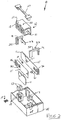
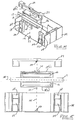
- Figure No. 2 is an exploded top perspective view of the preferred relay assembly according to the present invention showing from top to bottom, a bracket structure, an assembled coil assembly, linkage structures, contact-spring assemblies, permanent magnets, and the relay bottom casing.
- Figure No. 3 is an exploded top perspective view of the coil assembly according to the present invention.
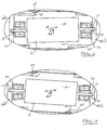
- Figure No. 4 is top plan view of the assembled and preferred relay assembly according to the present invention with relay housing cover removed to show internal components in an open switch assembly position.
- Figure No. 5 is top plan view of the assembled and preferred relay assembly according to the present invention with relay housing cover removed to show internal components in a closed switch assembly position.
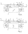
- Figure No. 6 is an enlarged plan view of the rotatable coil assembly (positioned intermediate fixed permanent magnet pairs) and contact-spring assemblies in the open switch assembly position.
- Figure No. 7 is an enlarged plan view of the rotatable coil assembly (positioned intermediate fixed permanent magnet pairs) and contact-spring assemblies in the closed switch assembly position.
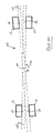
- Figure No. 8 is an enlarged diagrammatic type depiction of the rotatable coil assembly positioned intermediate fixed permanent magnet pairs in the open switch assembly position.
- Figure No. 9 is an enlarged diagrammatic type depiction of the rotatable coil assembly positioned intermediate fixed permanent magnet pairs in the closed switch assembly position.
- Figure No. 10 is an enlarged depiction of the contact-spring assemblies in the open switch assembly position.
- Figure No. 11 is an enlarged depiction of the contact-spring assemblies in the closed switch assembly position.
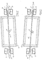
- Figure No. 12 is an enlarged plan view of the rotatable coil assembly of a multi-pole alternative embodiment according to the present invention showing the rotatable coil assembly in the open switch assembly position.
- Figure No. 13 is an enlarged plan view of the rotatable coil assembly of a multi-pole alternative embodiment according to the present invention showing the rotatable coil assembly in the closed switch assembly position.
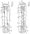
- Figure No. 14 is a fragmentary exploded top perspective view of the preferred relay assembly sectioned along the coil assembly axis of rotation.
- Figure No. 15 is a fragmentary exploded sectional view of the structures otherwise depicted in Figure No. 14 showing the coil axis orthogonal to the coil assembly axis of rotation.
- Figure No. 16 is top perspective view of an assembled and alternative multi-pole relay assembly according to the present invention with relay housing cover removed to show internal components.
- Figure No. 17 is an exploded top perspective view of the alternative multi-pole relay assembly according to the present invention showing from top to bottom, a bracket structure, an assembled coil assembly, linkage structures, contact-spring assemblies, permanent magnets, and the relay bottom casing.
- Figure No. 18 is top plan view of the assembled and alternative multi-pole relay assembly according to the present invention with relay housing cover removed to show internal components in an open switch assembly position.
- Figure No. 19 is top plan view of the assembled and alternative multi-pole relay assembly according to the present invention with relay housing cover removed to show internal components in a closed switch assembly position.
- Figure No. 20 is a diagrammatic depiction of X-shaped plane boundaries that define the limits of movement of the core termini intermediate the fixedly positioned permanent magnets according to the present invention.
- Referring now to the drawings, the preferred embodiment of the present invention concerns a so-called bi-stable electromagnetic relay (with X-drive motor)
assembly 10 as generally illustrated and referenced in Figure Nos. 1, 2, 4, and 5.Assembly 10 is believed to teach the basic structural concepts supporting the present invention, which basic structural concepts may be applied to either single pole assemblies as generally depicted and supported byassembly 10, or multiple pole assemblies. In this last regard, an exemplary four-pole assembly 20 is generally illustrated and referenced in Figure Nos. 16-19. - The
electromagnetic relay assembly 10 essentially functions to selectively enable current to pass throughswitch termini 11. Theelectromagnetic relay assembly 10 preferably comprises anelectromagnetic coil assembly 12, first and second pairs of opposedpermanent magnets 13, and a switch assembly comprising various components, including first and second linkage arms 14 (comprising one or more L-shaped portion(s)), and first andsecond spring arms 15, whicharms 15 are in electrical communication with, or otherwise (conductively) fastened extensions of the switch termini 11. - The
coil assembly 12 may preferably be thought to comprise a current-conductive coil 16 (with spool assembly 26), acoil core 17, and a coil housing 18 (comprising a coil lid 18(a) (outfitted with coil lid conductor(s) 25) and a coil base or coil box 18(b)). Thecoil 16 is wound around thecore 17, whichcore 17 is collinear with a coil axis as at 100. Thecoil 16 comprises electromagnet-driving termini as at 19, and thecore 17 comprises (linearly) opposed core termini as at 21. - Notably, the
coil housing 18 has a housing axis ofrotation 101, whichaxis 101 extends orthogonally relative to thecoil axis 100. The housing axis ofrotation 101 extends throughpin structures 22 formed in axial alignment on the coil lid 18(a) and the coil box 18(b) of thehousing 18, whichpin structures 22 are received in pin-receivingstructures 23 formed in abracket 27 andrelay housing 24. - The first and second pairs of opposed
permanent magnets 13 are respectively and fixedly obliquely positioned (via housing anchor structures 28) adjacent the core termini 21 such that the core termini 21 are respectively displacable intermediate the respective pairs ofmagnets 13. The opposed pairs ofpermanent magnets 13 each comprise substantially planar opposed magnet faces 29, which faces 29 extend in intersectingplanes 102 thereby exhibiting an X-shaped planar configuration as at 103 in Figure No. generally defining the boundaries of movement of the core termini 21. - In this last regard, it will be noted that the
core 17 has a thickness as at 104, and themagnets 13 are positioned (via anchor structures 28) accordingly so as to properly contact the core termini 21. In other words, the core 17 preferably comprises substantially planar opposed core faces as at 30 such that the core faces 30 and magnet faces 29 are similarly angled when contacting one another for maximizing contact surface area and enhancing current flow through the maximized contacting surface area intermediate thecore 17 andpermanent magnets 13. - It will be understood form a consideration of the drawings that the linkage arms 14 (or linkage arms 14(a) of the multi-pole embodiment) function to interconnect the core termini 21 and
spring arms 15. Thespring arms 15 each comprise (i.e. are in electrical communication with or otherwise conductively fastened to) opposed pairs ofcontacts 31 and a switch terminal as at 11. The opposed pairs ofcontacts 31 are juxtaposed adjacent one another such that when the switch assembly is in a closed position, thecontacts 31 contact one another as generally depicted in Figure Nos. 5, 7, 11, and 19. Conversely, the open switch assembly position is generally and comparatively depicted in Figure Nos. 4, 6, 10, and 18. - The
coil 16, when provided with current, functions to create a magnetic field as at 105, whichmagnetic field 15 is directable through thecore 17 and cooperable with the magnets 13 (as generally pole aligned and depicted in Figure Nos. 8 and 9) for imparting coil housing (pivot type) rotation (as at 106) about the housing axis ofrotation 101. The core termini 21 thus function to displace thelinkage arms 14, whichlinkage arms 14, in turn actuate thespring arms 15 intermediate the open position and the closed position as previously referenced. The closed position enables current to pass through the switch assembly via thecontacts 31 and the switch termini 11. - As earlier noted the linkage arms of
assembly 10 are preferably L-shaped from a top plan view and thus comprise a first link portion as at 32 and a second link portion as at 33. Withassembly 20, thelinkage arms 14 comprise a first link portion as at 34 and a series of second link portions as at 35 (or a series of interconnected L-shaped structures). Thesecond link portions assembly 10/20 respectively extend toward one another orthogonal to thefirst link portions assembly 10/20. The core termini 21 are connected to thefirst link portions spring arms 15 extend substantially parallel to thesecond link portions - The
spring arms 15 are preferably parallel to one another whether in the open or closed switch assembly positions and each comprise opposed faces, the inner faces 40 of which face one another as generally depicted and referenced in Figure Nos. 10 and 11. The opposed inner faces 40 are magnetically attractive to one another (as generally referenced at 107) during a short circuit scenario, and thus the magnetically attractive faces 40 function to maintain thecontacts 31 in the closed switch assembly position during a short circuit scenario. - In this last regard, it is noted that during a short circuit the magnetic fields generated inside a relay will grow as the current increases. The contacts, however, tend to separate during the rush of current. To structurally address this, the present invention enables the manufacturer to form one type of contact-spring assembly, and use the same assembly twice as generally depicted and illustrated by spring arm(s) 15,
termini 11, andcontacts 31. - It should be noted that half the current will flow through the top contact-spring assembly and half the current will flow through the bottom contact-spring assembly. Since these assemblies are carrying the same current in the same direction, the magnetic forces generated thereby are therefore equal. This means that when the bottom of the top spring is generating a magnetic field with a south polarity, the top of the bottom spring will generate a magnetic field with a north polarity. Since north and south attract one another (as at 107), the attraction forces the
contacts 31 into the closed position during a short circuit. The greater the current during the short circuit, the greater will be the magnetic field; therefore, themagnetic attraction 107 to maintain thecontacts 31 in a closed position is maximized. - The described contact-spring assembly is similar to existing assemblies insofar as the
terminals 11 andspring arms 15 are preferably constructed from copper whereby thespring arm 15 is placed on top of the copper terminal and then riveted together via thecontact buttons 31. By arranging thespring arms 15 so that faces 40 oppose one another, a resulting contact system allows for one input from a copper terminal, then splits the load through two springs and outputs the load again on the other copper terminal. Since the two springs (i.e. spring arms 15) are preferably identical in terms of their manufacturability, they will bear a very similar, if not identical, resistance. Furthermore, these two springs are running directly parallel to one another, resulting in the same magnetic fields generated around thespring arms 15. - The
spring arms 15 preferably comprise first and second spring portions or means for effecting bi-stability. The first spring portions or means are generally contemplated to be exemplified by resiliently bends in thearms 15 as generally depicted and referenced at 36. The first spring means are preferably relaxed when in an open switch assembly position and preferably actuated when in a closed switch assembly position, but not necessarily so. It is contemplated that the actuated first spring means may well function to dampen contact vibration intermediate thecontacts 31 when switching from the open switch assembly position to the closed switch assembly position. - The second spring portions or means are generally contemplated to be exemplified by resilient spring extensions as generally depicted and referenced at 37. The second spring portions or means 37 are preferably relaxed when in an open switch assembly position and preferably actuated when in a closed switch assembly position, but not necessarily so configured. It is contemplated that the actuated second spring means may well function to enhance damped contact vibration intermediate the
contacts 31 when switching from the open switch assembly position to the closed switch assembly position. - It should be noted that first spring means are preferably actuable adjacent the
first link portions second link portions contacts 31 when switching from the open switch assembly position to the closed switch assembly position. - In this last regard, it should be further noted that each contact pair is preferably positioned intermediate the spaced first and second damping means, which spaced damping means thus provide laterally opposed damping means relative to each contact pair for still further enhancing damped contact vibration intermediate the
contacts 31 when switching from the open switch assembly position to the closed switch assembly position. - As earlier noted, a major problem for all electro-mechanical switchgear is the contact bounce when closing into an electric load. To overcome this, the typical structural remedy is to include additional leaf or coil springs to buffer the bounce of the contacts. The present invention takes advantage of a simple stamping process which enables the incorporation of an integrated bounce reduction spring as exemplified by
resilient bends 36 andresilient extensions 37, which structural features are spaced laterally relative to thecontacts 31. The present design thus applies contact pressure both the left and right side of the contact, ensuring equal contact pressure and making sure that the contacts stay closed when the relay is operated. - While the above descriptions contain much specificity, this specificity should not be construed as limitations on the scope of the invention, but rather as an exemplification of the invention. For example, the invention may be said to essentially teach or disclose an electromagnetic relay assembly comprising a rotatable coil assembly, opposed pairs of attractive magnets, and a switch assembly.
- The coil assembly comprises a coil, a core, and certain core-rotating means as exemplified by the rotatable coil housing with peripheral, pivot type rotation-enabling structures. The core is preferably collinear with or parallel to the axis of the coil and comprises exposed and opposed core termini. Notably, the core-rotating means have an axis of rotation that extends orthogonally relative to the coil axis.
- The opposed pairs of attractive magnets are respectively and fixedly positioned adjacent the core termini such that the core termini are respectively displacable intermediate the magnet pairs. The coil function to create a magnetic field directable through the core into opposed magnets for imparting rotation about the axis of rotation. The core termini actuate the switch assembly intermediate an open position and a closed position, the latter of which positions enable current to pass through the switch assembly.
- The electromagnetic relay assemblies further comprise certain linkage means and opposed spring assemblies. The linkage means as exemplified by the
linkage arms 14 and 14(a) interconnect the core termini and spring assemblies. The spring assemblies essentially function to dampen contact vibration when switching from the open position to the closed position. The spring assemblies preferably comprise first and second spring means, which means are preferably relaxed when in the open position and preferably actuated when in the closed position, but the reverse structural configuration, namely that the first and second spring means may be relaxed when in the closed position and actuated when in the open position are also viable alternatives. - The first and second spring means are spaced from one another opposite the contacts for providing spaced, laterally opposed damping means for further enhancing damped contact vibration of the switch assembly when switching from the open to closed positions. The spring arms of the spring assemblies are preferably parallel to one another and comprise opposed arm faces as at 40. The opposed arm faces 40 are magnetically attractive to one another during a short circuit scenario, which magnetically attractive arm faces for maintaining the switch assembly in the closed position during the short circuit scenario.
- The attractive magnets comprise opposed magnet faces, which opposed magnet faces are substantially planar and extend in intersecting planes, and the core (termini) have substantially planar opposed core faces. The contacting core faces and magnet faces are similarly angled for maximizing contact surface area for further enhancing current flow through contacting surface area intermediate the core and magnet faces.
- In addition to the foregoing structural considerations, it is further believed that the inventive concepts discussed support certain new methodologies and/or processes. In this regard, it is contemplated that the foregoing structure considerations support a method for switching an electromagnetic relay comprising the steps of outfitting a coil assembly with means for rotating the coil assembly about an axis of rotation orthogonal to coil assembly axis whereafter a magnetic field may be created via the coil assembly and directed through the coil assembly into opposed magnets for imparting rotation about the axis of rotation. The coil assembly is then rotated (or pivoted) about the axis of rotation, and the switch assembly is actuated intermediate open and closed positions via the rotating coil assembly.
- The method is believed to further comprise the step of damping contact vibration via opposed contact-spring assemblies when displacing the switch assembly from the open to closed position, which may involve the step of laterally spacing the damping means relative to contacts of the switch assembly before the step of damping contact vibration. Certain faces (as at 40) of the contact-spring assemblies may be opposed before the step of damping contact vibration such that the opposed faces are magnetically attractive to one another during a short circuit scenario for maintaining the switch assembly in the closed position during said scenario.
- Although the invention has been described by reference to a number of embodiments it is not intended that the novel device or relay be limited thereby, but that modifications thereof are intended to be included as falling within the scope of the foregoing disclosure and the appended drawings. For example, the foregoing specifications support an electromagnetic relay assembly primarily intended for use as a single pole relay assembly as at 10. It is contemplated, however, that the invention may be applied in multi-pole relay assemblies as generally depicted and referenced by
assembly 20, having unique construction and functionality in their own right, but which are enabled by the teachings of the single pole embodiment primarily set forth in this disclosure.
Claims (5)
- An electromagnetic relay assembly (10), the electromagnetic relay assembly (10) comprising:a coil assembly (12), the coil assembly (12) comprising a core comprising opposed core terminals (21), a core axis (100), and an axis of rotation (101) orthogonal to the core axis (100), the core including the core terminals (21) being rotatable about the axis of rotation (101) such that the core axis (100) is rotatively displaceable intermediate X-shaped planar boundaries (103);a magnet pair (13) arranged opposite each core terminal (21), the core terminals (21) being respectively displaceable intermediate the pairs (13) via the axis of rotation (101);a switch assembly, the coil assembly (12) for creating a magnetic field (105), the magnetic field (105) being directable through the core terminals (21) into opposed magnets (13) for imparting rotation about the axis of rotation (101), the core terminals (21) for actuating the switch assembly intermediate an open position and a closed position; andlinkage means (14) and opposed contact-spring assemblies (15,11,31), the linkage means interconnecting the core terminals (21) and contact-spring assemblies (15,11,31), the contact-spring assemblies (15,11,31) for damping contact vibration when switching from the open to closed positions,characterised in thatthe coil assembly (12), including the core terminals (21) is rotatable about the axis of rotation (101), and in thatthe contact-spring assemblies comprise parallel spring arms (15), the spring arms (15) comprising opposed arm faces (40), the opposed arm faces (40) being magnetically attracted to one another during a short circuit scenario, the magnetically attractive arm faces (40) for maintaining the switch assembly in the closed position during the short circuit scenario.
- The electromagnetic relay assembly (10) of claim 1 wherein the contact-spring assemblies (15,11,31) each comprise spaced first and second spring means (36, 37) for providing spaced damping means, the spaced damping means for enhancing damped contact vibration of the switch assembly when switching from the open to closed positions.
- The electromagnetic relay assembly (10) of claim 2 wherein the switch assembly comprises opposed contact pairs (31), the contact pairs (31) each being positioned intermediate the spaced damping means (36, 37), the spaced damping means (36, 37) thus providing laterally opposed damping means for each contact pair (31) for enhancing damped contact vibration intermediate the contact pairs (31) when switching from the open to closed positions.
- A method for switching an electromagnetic relay, the method comprising the steps of:outfitting a coil assembly (12) the coil assembly (12) having a coil (16), having a core (17), and the core (17) having a core axis (100) with means for rotating the entire coil assembly (12) about an axis of rotation (101) orthogonal to the core axis (100);creating a magnetic field (105) via the coil assembly (12);directing the magnetic field (105) through the coil assembly (12) into opposed magnets (13) for imparting rotation about the axis of rotation (101);rotating the coil assembly (12) about the axis of rotation (101) such that the coil assembly axis is rotatively displaceable intermediate X-shaped planar boundaries (103);displacing a switch assembly intermediate open and closed positions via the rotating coil assembly; anddamping contact vibration via opposed contact-spring assemblies (15,11,31) when displacing the switch assembly from the open to closed position,wherein the method further comprises the step of opposing faces (40) of the contact-spring assemblies (15,11,31) before the step of damping contact vibration, the opposed faces (40) being magnetically attracted to one another during a short circuit scenario, the magnetically attracted arm faces (40) for maintaining the switch assembly in the closed position during said scenario.
- The method of claim 4 comprising the step of laterally spacing the damping means (36, 37) relative to contacts (31) of the switch assembly before the step of damping contact vibration.
Priority Applications (7)
| Application Number | Priority Date | Filing Date | Title |
|---|---|---|---|
| EP14162921.2A EP2752862B1 (en) | 2011-02-11 | 2012-02-09 | Bi-stable electromagnetic relay with X-drive motor |
| PL14162921T PL2752862T3 (en) | 2011-02-11 | 2012-02-09 | Bi-stable electromagnetic relay with X-drive motor |
| PL12746573T PL2673793T3 (en) | 2011-02-11 | 2012-02-09 | Bi-stable electromagnetic relay with x-drive motor |
| DK14162921.2T DK2752862T3 (en) | 2011-02-11 | 2012-02-09 | Bistable electromagnetic relay with the X-drive motor |
| EP14162923.8A EP2752863B1 (en) | 2011-02-11 | 2012-02-09 | Bi-stable electromagnetic relay with X-drive motor |
| PL14162923T PL2752863T3 (en) | 2011-02-11 | 2012-02-09 | Bi-stable electromagnetic relay with X-drive motor |
| DK14162923.8T DK2752863T3 (en) | 2011-02-11 | 2012-02-09 | BISTABLE ELECTROMAGNETIC RELAY WITH X DRIVE ENGINE |
Applications Claiming Priority (2)
| Application Number | Priority Date | Filing Date | Title |
|---|---|---|---|
| US12/931,820 US8514040B2 (en) | 2011-02-11 | 2011-02-11 | Bi-stable electromagnetic relay with x-drive motor |
| PCT/US2012/000078 WO2012112223A1 (en) | 2011-02-11 | 2012-02-09 | Bi-stable electromagnetic relay with x-drive motor |
Related Child Applications (4)
| Application Number | Title | Priority Date | Filing Date |
|---|---|---|---|
| EP14162921.2A Division-Into EP2752862B1 (en) | 2011-02-11 | 2012-02-09 | Bi-stable electromagnetic relay with X-drive motor |
| EP14162921.2A Division EP2752862B1 (en) | 2011-02-11 | 2012-02-09 | Bi-stable electromagnetic relay with X-drive motor |
| EP14162923.8A Division-Into EP2752863B1 (en) | 2011-02-11 | 2012-02-09 | Bi-stable electromagnetic relay with X-drive motor |
| EP14162923.8A Division EP2752863B1 (en) | 2011-02-11 | 2012-02-09 | Bi-stable electromagnetic relay with X-drive motor |
Publications (3)
| Publication Number | Publication Date |
|---|---|
| EP2673793A1 EP2673793A1 (en) | 2013-12-18 |
| EP2673793A4 EP2673793A4 (en) | 2015-03-11 |
| EP2673793B1 true EP2673793B1 (en) | 2019-03-27 |
Family
ID=46636436
Family Applications (3)
| Application Number | Title | Priority Date | Filing Date |
|---|---|---|---|
| EP14162921.2A Active EP2752862B1 (en) | 2011-02-11 | 2012-02-09 | Bi-stable electromagnetic relay with X-drive motor |
| EP14162923.8A Active EP2752863B1 (en) | 2011-02-11 | 2012-02-09 | Bi-stable electromagnetic relay with X-drive motor |
| EP12746573.0A Active EP2673793B1 (en) | 2011-02-11 | 2012-02-09 | Bi-stable electromagnetic relay with x-drive motor |
Family Applications Before (2)
| Application Number | Title | Priority Date | Filing Date |
|---|---|---|---|
| EP14162921.2A Active EP2752862B1 (en) | 2011-02-11 | 2012-02-09 | Bi-stable electromagnetic relay with X-drive motor |
| EP14162923.8A Active EP2752863B1 (en) | 2011-02-11 | 2012-02-09 | Bi-stable electromagnetic relay with X-drive motor |
Country Status (21)
| Country | Link |
|---|---|
| US (1) | US8514040B2 (en) |
| EP (3) | EP2752862B1 (en) |
| JP (1) | JP5750170B2 (en) |
| KR (1) | KR101592183B1 (en) |
| CN (1) | CN103493166B (en) |
| AU (1) | AU2012218143B2 (en) |
| BR (1) | BR112013020479B1 (en) |
| CA (1) | CA2826970C (en) |
| DK (3) | DK2752863T3 (en) |
| ES (3) | ES2732677T3 (en) |
| HR (1) | HRP20160301T1 (en) |
| HU (2) | HUE035548T2 (en) |
| MX (1) | MX2013009290A (en) |
| PL (3) | PL2673793T3 (en) |
| PT (2) | PT2752863T (en) |
| RS (2) | RS54694B1 (en) |
| RU (1) | RU2548904C2 (en) |
| SG (1) | SG192699A1 (en) |
| SI (1) | SI2752862T1 (en) |
| WO (1) | WO2012112223A1 (en) |
| ZA (1) | ZA201306147B (en) |
Families Citing this family (23)
| Publication number | Priority date | Publication date | Assignee | Title |
|---|---|---|---|---|
| US9343931B2 (en) | 2012-04-06 | 2016-05-17 | David Deak | Electrical generator with rotational gaussian surface magnet and stationary coil |
| CN202650990U (en) * | 2012-07-02 | 2013-01-02 | 宁波福特继电器有限公司 | Miniature high power magnetic latching relay |
| GB201402560D0 (en) * | 2014-02-13 | 2014-04-02 | Johnson Electric Sa | Improvements in or relating to electrical contactors |
| GB201407705D0 (en) * | 2014-05-01 | 2014-06-18 | Johnson Electric Sa | Improvements in electrical contact sets |
| JP6414453B2 (en) * | 2014-12-05 | 2018-10-31 | オムロン株式会社 | Electromagnetic relay |
| JP2016110843A (en) * | 2014-12-05 | 2016-06-20 | オムロン株式会社 | Electromagnetic relay |
| CN107077996B (en) | 2014-12-05 | 2019-03-29 | 欧姆龙株式会社 | Electromagnetic relay |
| US9843248B2 (en) * | 2015-06-04 | 2017-12-12 | David Deak, SR. | Rocker action electric generator |
| KR101951428B1 (en) * | 2015-07-15 | 2019-02-22 | 엘에스산전 주식회사 | Latch Relay |
| DE102016112663B4 (en) * | 2016-07-11 | 2018-04-12 | Phoenix Contact Gmbh & Co. Kg | Electromechanical relay, terminal block and electromechanical relay module |
| DE102016117671A1 (en) * | 2016-09-20 | 2018-03-22 | Panasonic Industrial Devices Europe Gmbh | Electromagnetic relay |
| CN106971913B (en) * | 2017-04-01 | 2018-09-21 | 厦门宏发电力电器有限公司 | A kind of magnetic latching relay that can resist short circuit current |
| CN106971912B (en) * | 2017-04-01 | 2019-01-01 | 厦门宏发电力电器有限公司 | A kind of connection structure between the movable spring assembly and pedestal of relay |
| JP6922534B2 (en) * | 2017-08-04 | 2021-08-18 | オムロン株式会社 | Electromagnetic relay |
| WO2019089435A1 (en) | 2017-10-30 | 2019-05-09 | Deak David Sr | Magnetic momentum transfer generator |
| DE102018208119A1 (en) * | 2018-05-23 | 2019-11-28 | Ellenberger & Poensgen Gmbh | Separating device for DC interruption of a current path and circuit breaker |
| US10923261B2 (en) * | 2018-10-30 | 2021-02-16 | Microsoft Technology Licensing, Llc | Magnetic fastening assembly |
| US11368079B2 (en) | 2019-11-06 | 2022-06-21 | David Deak, SR. | Offset triggered cantilever actuated generator |
| CH716470A1 (en) | 2019-07-30 | 2021-02-15 | Elesta Gmbh Ostfildern De Zweigniederlassung Bad Ragaz | Double armature relay. |
| CN110570642B (en) * | 2019-09-04 | 2021-05-18 | 航宇救生装备有限公司 | Power supply on-off control circuit and control method for remote control system |
| WO2021102316A1 (en) | 2019-11-21 | 2021-05-27 | Wepower Technologies Llc | Tangentially actuated magnetic momentum transfer generator |
| CN211428099U (en) * | 2019-12-17 | 2020-09-04 | 泰科电子(深圳)有限公司 | Auxiliary contact system of contactor |
| CN115440515A (en) * | 2021-06-04 | 2022-12-06 | 天津首瑞智能电气有限公司 | Multiple suction superimposed electric switch |
Family Cites Families (46)
| Publication number | Priority date | Publication date | Assignee | Title |
|---|---|---|---|---|
| US1959861A (en) * | 1932-01-25 | 1934-05-22 | Oakes Prod Corp | Automatic starting system and mechanism |
| US2145821A (en) * | 1935-06-04 | 1939-01-31 | Wallace & Tiernan Inc | Selective relay |
| GB571997A (en) * | 1944-01-25 | 1945-09-18 | Norman Maxwell Best | Improvements in or relating to electric circuit breakers provided with overload release devices |
| US2784327A (en) * | 1955-05-09 | 1957-03-05 | John F Drescher | Impulse generator |
| US2832902A (en) * | 1956-09-17 | 1958-04-29 | John F Drescher | Impulse generator |
| US2904707A (en) * | 1957-01-11 | 1959-09-15 | John F Drescher | Impulse generator |
| US3582695A (en) * | 1969-08-18 | 1971-06-01 | Scm Corp | Mechanically toggled electrical pulse generator |
| JPS4918139B1 (en) * | 1969-10-16 | 1974-05-08 | ||
| DE2454967C3 (en) * | 1974-05-15 | 1981-12-24 | Hans 8024 Deisenhofen Sauer | Poled electromagnetic relay |
| SU778718A3 (en) * | 1974-09-30 | 1980-11-07 | Матсушита Электрик Воркс (Фирма) | Electromagnetic relay |
| JPS5238171A (en) * | 1975-09-20 | 1977-03-24 | Matsushita Electric Works Ltd | Contact switching mechanism |
| JPS5719786Y2 (en) * | 1977-08-09 | 1982-04-27 | ||
| DE3063933D1 (en) * | 1979-01-25 | 1983-08-04 | Sds Elektro Gmbh | Arrangement of contact springs for polarized electromagnetic relays |
| JPS55145313A (en) * | 1979-04-27 | 1980-11-12 | Matsushita Electric Works Ltd | Polar electromagnetic device |
| JPS57166015A (en) * | 1981-04-03 | 1982-10-13 | Omron Tateisi Electronics Co | Polarized electromagnet device |
| DE3220985A1 (en) * | 1982-06-03 | 1983-12-08 | Siemens AG, 1000 Berlin und 8000 München | ELECTROMAGNETIC SWIVEL RELAY |
| DE3425889C1 (en) * | 1984-07-13 | 1986-02-13 | SDS-Relais AG, 8024 Deisenhofen | Safety relay |
| EP0186393B1 (en) * | 1984-12-24 | 1990-03-07 | Matsushita Electric Works, Ltd. | Remotely controllable relay |
| DE3520773C1 (en) * | 1985-05-29 | 1989-07-20 | SDS-Relais AG, 8024 Deisenhofen | Electromagnetic relay |
| US4713638A (en) * | 1985-10-25 | 1987-12-15 | Nec Corporation | Polarized electromagnetic relay |
| AT388467B (en) * | 1987-08-27 | 1989-06-26 | Schrack Elektronik Ag | RELAY DRIVE FOR A POLARIZED RELAY |
| GB9012475D0 (en) * | 1990-06-05 | 1990-07-25 | P E D Limited | Solenoids |
| US5359305A (en) * | 1992-06-15 | 1994-10-25 | Matsushita Electric Works, Ltd. | Electromagnetic relay |
| DE4300594A1 (en) | 1993-01-13 | 1994-07-14 | Hengstler Bauelemente | Safety relay with positively driven contact set and monostable drive |
| FR2739487B1 (en) | 1995-09-28 | 1997-10-31 | Schneider Electric Sa | CONTROL AND SIGNALING DEVICE FOR PROTECTIVE APPARATUS |
| DE19882165T1 (en) | 1997-03-08 | 2000-03-30 | Blp Components Ltd | Two-pole contactor |
| US6025766A (en) | 1997-04-11 | 2000-02-15 | Siemens Energy & Automation, Inc. | Trip mechanism for an overload relay |
| DE19715261C1 (en) | 1997-04-12 | 1998-12-10 | Gruner Ag | Relay |
| US5910759A (en) | 1998-05-15 | 1999-06-08 | Siemens Energy & Automation, Inc. | Contact mechanism for electronic overload relays |
| US5994987A (en) | 1998-05-15 | 1999-11-30 | Siemens Energy & Automation, Inc. | Contact mechanism for electronic overload relays |
| US6246306B1 (en) | 1999-02-04 | 2001-06-12 | Klaus A. Gruner | Electromagnetic relay with pressure spring |
| US6252478B1 (en) | 1999-02-04 | 2001-06-26 | Klaus A. Gruner | Electromagnetic relay |
| US6046660A (en) | 1999-04-07 | 2000-04-04 | Gruner; Klaus A. | Latching magnetic relay assembly with a linear motor |
| US6320485B1 (en) | 1999-04-07 | 2001-11-20 | Klaus A. Gruner | Electromagnetic relay assembly with a linear motor |
| CN1221002C (en) | 1999-10-26 | 2005-09-28 | 松下电工株式会社 | Electromagnetic relay |
| US6563409B2 (en) | 2001-03-26 | 2003-05-13 | Klaus A. Gruner | Latching magnetic relay assembly |
| JP4334158B2 (en) * | 2001-03-26 | 2009-09-30 | 富士通コンポーネント株式会社 | Electromagnetic relay |
| DE10162585C1 (en) | 2001-12-19 | 2003-04-24 | Gruner Ag | Electrical relay has auxiliary spring acting on switched contact spring in closed contact position for reducing rebound |
| DE10249697B3 (en) | 2002-10-25 | 2004-04-15 | Gruner Ag | Electromagnetic relay with 2 parallel contact springs held in contact closed position via respective ends of flat spring pivoted at its centre |
| JP4168733B2 (en) | 2002-11-12 | 2008-10-22 | オムロン株式会社 | Electromagnetic relay |
| DE10315765C5 (en) * | 2003-04-07 | 2021-03-11 | Enocean Gmbh | Use of an electromagnetic energy converter |
| US6949997B2 (en) | 2003-09-26 | 2005-09-27 | Rockwell Automation Technologies, Inc. | Bi-stable trip-free relay configuration |
| JP4424260B2 (en) | 2005-06-07 | 2010-03-03 | オムロン株式会社 | Electromagnetic relay |
| US7710224B2 (en) | 2007-08-01 | 2010-05-04 | Clodi, L.L.C. | Electromagnetic relay assembly |
| US7659800B2 (en) * | 2007-08-01 | 2010-02-09 | Philipp Gruner | Electromagnetic relay assembly |
| MX2011008110A (en) * | 2009-02-04 | 2011-12-08 | Clodi L L C | Electromagnetic relay assembly. |
-
2011
- 2011-02-11 US US12/931,820 patent/US8514040B2/en active Active
-
2012
- 2012-02-09 BR BR112013020479-6A patent/BR112013020479B1/en active IP Right Grant
- 2012-02-09 RS RS20160224A patent/RS54694B1/en unknown
- 2012-02-09 DK DK14162923.8T patent/DK2752863T3/en active
- 2012-02-09 PT PT141629238T patent/PT2752863T/en unknown
- 2012-02-09 RU RU2013139699/07A patent/RU2548904C2/en active
- 2012-02-09 MX MX2013009290A patent/MX2013009290A/en active IP Right Grant
- 2012-02-09 SG SG2013060686A patent/SG192699A1/en unknown
- 2012-02-09 EP EP14162921.2A patent/EP2752862B1/en active Active
- 2012-02-09 RS RS20171349A patent/RS56806B1/en unknown
- 2012-02-09 JP JP2013553438A patent/JP5750170B2/en active Active
- 2012-02-09 HU HUE14162923A patent/HUE035548T2/en unknown
- 2012-02-09 DK DK12746573.0T patent/DK2673793T3/en active
- 2012-02-09 CA CA2826970A patent/CA2826970C/en active Active
- 2012-02-09 PL PL12746573T patent/PL2673793T3/en unknown
- 2012-02-09 HU HUE14162921A patent/HUE028540T2/en unknown
- 2012-02-09 ES ES12746573T patent/ES2732677T3/en active Active
- 2012-02-09 DK DK14162921.2T patent/DK2752862T3/en active
- 2012-02-09 ES ES14162923.8T patent/ES2657412T3/en active Active
- 2012-02-09 ES ES14162921.2T patent/ES2567629T3/en active Active
- 2012-02-09 PT PT12746573T patent/PT2673793T/en unknown
- 2012-02-09 CN CN201280008648.2A patent/CN103493166B/en active Active
- 2012-02-09 AU AU2012218143A patent/AU2012218143B2/en active Active
- 2012-02-09 PL PL14162921T patent/PL2752862T3/en unknown
- 2012-02-09 KR KR1020137023892A patent/KR101592183B1/en active IP Right Grant
- 2012-02-09 WO PCT/US2012/000078 patent/WO2012112223A1/en active Application Filing
- 2012-02-09 EP EP14162923.8A patent/EP2752863B1/en active Active
- 2012-02-09 SI SI201230523A patent/SI2752862T1/en unknown
- 2012-02-09 EP EP12746573.0A patent/EP2673793B1/en active Active
- 2012-02-09 PL PL14162923T patent/PL2752863T3/en unknown
-
2013
- 2013-08-15 ZA ZA2013/06147A patent/ZA201306147B/en unknown
-
2016
- 2016-03-23 HR HRP20160301TT patent/HRP20160301T1/en unknown
Non-Patent Citations (1)
| Title |
|---|
| None * |
Also Published As
Similar Documents
| Publication | Publication Date | Title |
|---|---|---|
| EP2673793B1 (en) | Bi-stable electromagnetic relay with x-drive motor | |
| EP2394285B1 (en) | Electromagnetic relay assembly | |
| US7710224B2 (en) | Electromagnetic relay assembly | |
| AU2009339409B2 (en) | Electromagnetic relay assembly | |
| US20090033446A1 (en) | Electromagnetic relay assembly | |
| US7889032B2 (en) | Electromagnetic relay | |
| US20150048909A1 (en) | Polarized Electromagnetic Relay and Method for Production Thereof | |
| CN210120089U (en) | Ammeter connection structure capable of opening and closing circuit and electric energy meter comprising same |
Legal Events
| Date | Code | Title | Description |
|---|---|---|---|
| PUAI | Public reference made under article 153(3) epc to a published international application that has entered the european phase |
Free format text: ORIGINAL CODE: 0009012 |
|
| 17P | Request for examination filed |
Effective date: 20130809 |
|
| AK | Designated contracting states |
Kind code of ref document: A1 Designated state(s): AL AT BE BG CH CY CZ DE DK EE ES FI FR GB GR HR HU IE IS IT LI LT LU LV MC MK MT NL NO PL PT RO RS SE SI SK SM TR |
|
| DAX | Request for extension of the european patent (deleted) | ||
| A4 | Supplementary search report drawn up and despatched |
Effective date: 20150211 |
|
| RIC1 | Information provided on ipc code assigned before grant |
Ipc: H01H 1/50 20060101AFI20150205BHEP Ipc: H01H 51/22 20060101ALI20150205BHEP Ipc: H01H 50/44 20060101ALI20150205BHEP Ipc: H01H 1/54 20060101ALI20150205BHEP Ipc: H01H 50/64 20060101ALI20150205BHEP Ipc: H01H 50/54 20060101ALI20150205BHEP Ipc: H01H 50/30 20060101ALI20150205BHEP |
|
| RAP1 | Party data changed (applicant data changed or rights of an application transferred) |
Owner name: HONGFA HOLDINGS U.S., INC. |
|
| STAA | Information on the status of an ep patent application or granted ep patent |
Free format text: STATUS: EXAMINATION IS IN PROGRESS |
|
| 17Q | First examination report despatched |
Effective date: 20170420 |
|
| GRAP | Despatch of communication of intention to grant a patent |
Free format text: ORIGINAL CODE: EPIDOSNIGR1 |
|
| STAA | Information on the status of an ep patent application or granted ep patent |
Free format text: STATUS: GRANT OF PATENT IS INTENDED |
|
| INTG | Intention to grant announced |
Effective date: 20180928 |
|
| GRAS | Grant fee paid |
Free format text: ORIGINAL CODE: EPIDOSNIGR3 |
|
| GRAA | (expected) grant |
Free format text: ORIGINAL CODE: 0009210 |
|
| STAA | Information on the status of an ep patent application or granted ep patent |
Free format text: STATUS: THE PATENT HAS BEEN GRANTED |
|
| RAP1 | Party data changed (applicant data changed or rights of an application transferred) |
Owner name: HONGFA HOLDINGS U.S., INC. |
|
| AK | Designated contracting states |
Kind code of ref document: B1 Designated state(s): AL AT BE BG CH CY CZ DE DK EE ES FI FR GB GR HR HU IE IS IT LI LT LU LV MC MK MT NL NO PL PT RO RS SE SI SK SM TR |
|
| REG | Reference to a national code |
Ref country code: GB Ref legal event code: FG4D |
|
| REG | Reference to a national code |
Ref country code: CH Ref legal event code: EP |
|
| REG | Reference to a national code |
Ref country code: AT Ref legal event code: REF Ref document number: 1114014 Country of ref document: AT Kind code of ref document: T Effective date: 20190415 |
|
| REG | Reference to a national code |
Ref country code: IE Ref legal event code: FG4D |
|
| REG | Reference to a national code |
Ref country code: DE Ref legal event code: R096 Ref document number: 602012058287 Country of ref document: DE |
|
| REG | Reference to a national code |
Ref country code: PT Ref legal event code: SC4A Ref document number: 2673793 Country of ref document: PT Date of ref document: 20190604 Kind code of ref document: T Free format text: AVAILABILITY OF NATIONAL TRANSLATION Effective date: 20190517 |
|
| REG | Reference to a national code |
Ref country code: RO Ref legal event code: EPE |
|
| REG | Reference to a national code |
Ref country code: DK Ref legal event code: T3 Effective date: 20190617 |
|
| PG25 | Lapsed in a contracting state [announced via postgrant information from national office to epo] |
Ref country code: NO Free format text: LAPSE BECAUSE OF FAILURE TO SUBMIT A TRANSLATION OF THE DESCRIPTION OR TO PAY THE FEE WITHIN THE PRESCRIBED TIME-LIMIT Effective date: 20190627 Ref country code: LT Free format text: LAPSE BECAUSE OF FAILURE TO SUBMIT A TRANSLATION OF THE DESCRIPTION OR TO PAY THE FEE WITHIN THE PRESCRIBED TIME-LIMIT Effective date: 20190327 Ref country code: SE Free format text: LAPSE BECAUSE OF FAILURE TO SUBMIT A TRANSLATION OF THE DESCRIPTION OR TO PAY THE FEE WITHIN THE PRESCRIBED TIME-LIMIT Effective date: 20190327 Ref country code: FI Free format text: LAPSE BECAUSE OF FAILURE TO SUBMIT A TRANSLATION OF THE DESCRIPTION OR TO PAY THE FEE WITHIN THE PRESCRIBED TIME-LIMIT Effective date: 20190327 |
|
| REG | Reference to a national code |
Ref country code: NL Ref legal event code: MP Effective date: 20190327 |
|
| PG25 | Lapsed in a contracting state [announced via postgrant information from national office to epo] |
Ref country code: HR Free format text: LAPSE BECAUSE OF FAILURE TO SUBMIT A TRANSLATION OF THE DESCRIPTION OR TO PAY THE FEE WITHIN THE PRESCRIBED TIME-LIMIT Effective date: 20190327 Ref country code: NL Free format text: LAPSE BECAUSE OF FAILURE TO SUBMIT A TRANSLATION OF THE DESCRIPTION OR TO PAY THE FEE WITHIN THE PRESCRIBED TIME-LIMIT Effective date: 20190327 Ref country code: LV Free format text: LAPSE BECAUSE OF FAILURE TO SUBMIT A TRANSLATION OF THE DESCRIPTION OR TO PAY THE FEE WITHIN THE PRESCRIBED TIME-LIMIT Effective date: 20190327 Ref country code: BG Free format text: LAPSE BECAUSE OF FAILURE TO SUBMIT A TRANSLATION OF THE DESCRIPTION OR TO PAY THE FEE WITHIN THE PRESCRIBED TIME-LIMIT Effective date: 20190627 Ref country code: RS Free format text: LAPSE BECAUSE OF FAILURE TO SUBMIT A TRANSLATION OF THE DESCRIPTION OR TO PAY THE FEE WITHIN THE PRESCRIBED TIME-LIMIT Effective date: 20190327 Ref country code: GR Free format text: LAPSE BECAUSE OF FAILURE TO SUBMIT A TRANSLATION OF THE DESCRIPTION OR TO PAY THE FEE WITHIN THE PRESCRIBED TIME-LIMIT Effective date: 20190628 |
|
| REG | Reference to a national code |
Ref country code: AT Ref legal event code: MK05 Ref document number: 1114014 Country of ref document: AT Kind code of ref document: T Effective date: 20190327 |
|
| PG25 | Lapsed in a contracting state [announced via postgrant information from national office to epo] |
Ref country code: EE Free format text: LAPSE BECAUSE OF FAILURE TO SUBMIT A TRANSLATION OF THE DESCRIPTION OR TO PAY THE FEE WITHIN THE PRESCRIBED TIME-LIMIT Effective date: 20190327 Ref country code: SK Free format text: LAPSE BECAUSE OF FAILURE TO SUBMIT A TRANSLATION OF THE DESCRIPTION OR TO PAY THE FEE WITHIN THE PRESCRIBED TIME-LIMIT Effective date: 20190327 Ref country code: AL Free format text: LAPSE BECAUSE OF FAILURE TO SUBMIT A TRANSLATION OF THE DESCRIPTION OR TO PAY THE FEE WITHIN THE PRESCRIBED TIME-LIMIT Effective date: 20190327 Ref country code: IT Free format text: LAPSE BECAUSE OF FAILURE TO SUBMIT A TRANSLATION OF THE DESCRIPTION OR TO PAY THE FEE WITHIN THE PRESCRIBED TIME-LIMIT Effective date: 20190327 |
|
| REG | Reference to a national code |
Ref country code: ES Ref legal event code: FG2A Ref document number: 2732677 Country of ref document: ES Kind code of ref document: T3 Effective date: 20191125 |
|
| PG25 | Lapsed in a contracting state [announced via postgrant information from national office to epo] |
Ref country code: SM Free format text: LAPSE BECAUSE OF FAILURE TO SUBMIT A TRANSLATION OF THE DESCRIPTION OR TO PAY THE FEE WITHIN THE PRESCRIBED TIME-LIMIT Effective date: 20190327 |
|
| PG25 | Lapsed in a contracting state [announced via postgrant information from national office to epo] |
Ref country code: AT Free format text: LAPSE BECAUSE OF FAILURE TO SUBMIT A TRANSLATION OF THE DESCRIPTION OR TO PAY THE FEE WITHIN THE PRESCRIBED TIME-LIMIT Effective date: 20190327 Ref country code: IS Free format text: LAPSE BECAUSE OF FAILURE TO SUBMIT A TRANSLATION OF THE DESCRIPTION OR TO PAY THE FEE WITHIN THE PRESCRIBED TIME-LIMIT Effective date: 20190727 |
|
| REG | Reference to a national code |
Ref country code: DE Ref legal event code: R097 Ref document number: 602012058287 Country of ref document: DE |
|
| PLBE | No opposition filed within time limit |
Free format text: ORIGINAL CODE: 0009261 |
|
| STAA | Information on the status of an ep patent application or granted ep patent |
Free format text: STATUS: NO OPPOSITION FILED WITHIN TIME LIMIT |
|
| PG25 | Lapsed in a contracting state [announced via postgrant information from national office to epo] |
Ref country code: SI Free format text: LAPSE BECAUSE OF FAILURE TO SUBMIT A TRANSLATION OF THE DESCRIPTION OR TO PAY THE FEE WITHIN THE PRESCRIBED TIME-LIMIT Effective date: 20190327 |
|
| 26N | No opposition filed |
Effective date: 20200103 |
|
| PG25 | Lapsed in a contracting state [announced via postgrant information from national office to epo] |
Ref country code: TR Free format text: LAPSE BECAUSE OF FAILURE TO SUBMIT A TRANSLATION OF THE DESCRIPTION OR TO PAY THE FEE WITHIN THE PRESCRIBED TIME-LIMIT Effective date: 20190327 |
|
| REG | Reference to a national code |
Ref country code: CH Ref legal event code: PL |
|
| REG | Reference to a national code |
Ref country code: BE Ref legal event code: MM Effective date: 20200229 |
|
| PG25 | Lapsed in a contracting state [announced via postgrant information from national office to epo] |
Ref country code: MC Free format text: LAPSE BECAUSE OF FAILURE TO SUBMIT A TRANSLATION OF THE DESCRIPTION OR TO PAY THE FEE WITHIN THE PRESCRIBED TIME-LIMIT Effective date: 20190327 Ref country code: LU Free format text: LAPSE BECAUSE OF NON-PAYMENT OF DUE FEES Effective date: 20200209 |
|
| REG | Reference to a national code |
Ref country code: CH Ref legal event code: AECN Free format text: DAS PATENT WURDE AUFGRUND DES WEITERBEHANDLUNGSANTRAGS VOM 11.11.2020 REAKTIVIERT. Ref country code: CH Ref legal event code: NV Representative=s name: ISLER AND PEDRAZZINI AG, CH |
|
| PG25 | Lapsed in a contracting state [announced via postgrant information from national office to epo] |
Ref country code: CH Free format text: LAPSE BECAUSE OF NON-PAYMENT OF DUE FEES Effective date: 20200229 Ref country code: LI Free format text: LAPSE BECAUSE OF NON-PAYMENT OF DUE FEES Effective date: 20200229 |
|
| PG25 | Lapsed in a contracting state [announced via postgrant information from national office to epo] |
Ref country code: LI Free format text: LAPSE BECAUSE OF NON-PAYMENT OF DUE FEES Effective date: 20200229 Ref country code: CH Free format text: LAPSE BECAUSE OF NON-PAYMENT OF DUE FEES Effective date: 20200229 Ref country code: IE Free format text: LAPSE BECAUSE OF NON-PAYMENT OF DUE FEES Effective date: 20200209 |
|
| PGRI | Patent reinstated in contracting state [announced from national office to epo] |
Ref country code: LI Effective date: 20201113 Ref country code: CH Effective date: 20201113 |
|
| PG25 | Lapsed in a contracting state [announced via postgrant information from national office to epo] |
Ref country code: BE Free format text: LAPSE BECAUSE OF NON-PAYMENT OF DUE FEES Effective date: 20200229 |
|
| PG25 | Lapsed in a contracting state [announced via postgrant information from national office to epo] |
Ref country code: MT Free format text: LAPSE BECAUSE OF FAILURE TO SUBMIT A TRANSLATION OF THE DESCRIPTION OR TO PAY THE FEE WITHIN THE PRESCRIBED TIME-LIMIT Effective date: 20190327 Ref country code: CY Free format text: LAPSE BECAUSE OF FAILURE TO SUBMIT A TRANSLATION OF THE DESCRIPTION OR TO PAY THE FEE WITHIN THE PRESCRIBED TIME-LIMIT Effective date: 20190327 |
|
| PG25 | Lapsed in a contracting state [announced via postgrant information from national office to epo] |
Ref country code: MK Free format text: LAPSE BECAUSE OF FAILURE TO SUBMIT A TRANSLATION OF THE DESCRIPTION OR TO PAY THE FEE WITHIN THE PRESCRIBED TIME-LIMIT Effective date: 20190327 |
|
| PGFP | Annual fee paid to national office [announced via postgrant information from national office to epo] |
Ref country code: ES Payment date: 20240311 Year of fee payment: 13 |
|
| PGFP | Annual fee paid to national office [announced via postgrant information from national office to epo] |
Ref country code: RO Payment date: 20240205 Year of fee payment: 13 Ref country code: DE Payment date: 20240215 Year of fee payment: 13 Ref country code: CZ Payment date: 20240122 Year of fee payment: 13 Ref country code: CH Payment date: 20240301 Year of fee payment: 13 Ref country code: PT Payment date: 20240117 Year of fee payment: 13 Ref country code: GB Payment date: 20240117 Year of fee payment: 13 |
|
| PGFP | Annual fee paid to national office [announced via postgrant information from national office to epo] |
Ref country code: PL Payment date: 20240118 Year of fee payment: 13 Ref country code: FR Payment date: 20240126 Year of fee payment: 13 Ref country code: DK Payment date: 20240219 Year of fee payment: 13 |