JP6922534B2 - Electromagnetic relay - Google Patents
Electromagnetic relay Download PDFInfo
- Publication number
- JP6922534B2 JP6922534B2 JP2017151945A JP2017151945A JP6922534B2 JP 6922534 B2 JP6922534 B2 JP 6922534B2 JP 2017151945 A JP2017151945 A JP 2017151945A JP 2017151945 A JP2017151945 A JP 2017151945A JP 6922534 B2 JP6922534 B2 JP 6922534B2
- Authority
- JP
- Japan
- Prior art keywords
- movable contact
- side terminal
- piece
- fixed
- housing
- Prior art date
- Legal status (The legal status is an assumption and is not a legal conclusion. Google has not performed a legal analysis and makes no representation as to the accuracy of the status listed.)
- Active
Links
Images


Classifications
-
- H—ELECTRICITY
- H01—ELECTRIC ELEMENTS
- H01H—ELECTRIC SWITCHES; RELAYS; SELECTORS; EMERGENCY PROTECTIVE DEVICES
- H01H50/00—Details of electromagnetic relays
- H01H50/54—Contact arrangements
- H01H50/56—Contact spring sets
Description
本発明は、複数極の電磁継電器に関する。 The present invention relates to a multi-pole electromagnetic relay.
特許文献1に開示されている電磁継電器は、内部に収容部を有する矩形箱形のハウジングと、このハウジングに固定された2つの固定接点側端子および2つの可動接点側端子とを備えている。この電磁継電器の収容部には、各固定接点側端子に設けられた2つの固定接点部と、各可動接点側端子に設けられた2つの可動接触片と、各可動接触片に設けられかつ各固定接点部に対向するように配置された2つの可動接点部と、供給された電流の方向により極性が反転する電磁石部と、電磁石部の極性に応じて異なる方向に回動する1つの回動ブロックとを備えている。 The electromagnetic relay disclosed in Patent Document 1 includes a rectangular box-shaped housing having an accommodating portion inside, two fixed contact side terminals fixed to the housing, and two movable contact side terminals. The accommodating portion of this electromagnetic relay includes two fixed contact portions provided on each fixed contact side terminal, two movable contact pieces provided on each movable contact side terminal, and each movable contact piece provided on each movable contact piece. Two movable contact parts arranged so as to face the fixed contact part, an electromagnet part whose polarity is reversed depending on the direction of the supplied current, and one rotation that rotates in a different direction depending on the polarity of the electromagnet part. It has a block.
前記電磁継電器では、固定接点側端子、可動接点側端子および可動接触片で構成され、可動接触片が、ベース内で可動接点部が固定接点部に対して接触または開離する方向に並んで対向配置されている2つの回路が形成されている。各可動接触片は、相互に接近する方向に弾性変形することで、可動接点部を対向する固定接点部に接触させ、相互に離れる方向に弾性変形することで、可動接点部を対向する固定接点部から開離させるように配置されている。 The electromagnetic relay is composed of a fixed contact side terminal, a movable contact side terminal, and a movable contact piece, and the movable contact pieces face each other side by side in a direction in which the movable contact portion contacts or opens with respect to the fixed contact portion in the base. Two arranged circuits are formed. Each movable contact piece is elastically deformed in the direction of approaching each other to bring the movable contact portion into contact with the opposite fixed contact portion, and elastically deformed in the direction of being separated from each other, thereby causing the movable contact portion to face the fixed contact portion. It is arranged so as to be separated from the part.
しかし、前記電磁継電器では、固定接点側端子および可動接点側端子のいずれから電流が供給された場合であっても、2つの可動接触片を流れる電流の方向が相互に異なるため、各可動接触片に対して相互に離れる方向に電磁反発力が発生する。すなわち、通電時に各可動接点部が対応する固定接点部から開離する方向に電磁反発力が働き、各可動接点部の対応する固定接点部に対する接触信頼性が低下する場合がある。 However, in the electromagnetic relay, the directions of the currents flowing through the two movable contact pieces are different from each other regardless of whether the current is supplied from the fixed contact side terminal or the movable contact side terminal, so that each movable contact piece. Electromagnetic repulsive force is generated in the direction away from each other. That is, when energized, an electromagnetic repulsive force acts in a direction in which each movable contact portion separates from the corresponding fixed contact portion, and the contact reliability of each movable contact portion with respect to the corresponding fixed contact portion may decrease.
そこで、本発明は、各可動接点部の対応する固定接点部に対する接触信頼性を向上できる複数極の電磁継電器を提供することを課題とする。 Therefore, it is an object of the present invention to provide a multi-pole electromagnetic relay capable of improving the contact reliability of each movable contact portion with respect to the corresponding fixed contact portion.
本発明の一態様の電磁継電器は、
内部に収容部を有する箱形の絶縁性のハウジングと、
前記ハウジングに固定され、前記ハウジングの外部から前記収容部まで延びていると共に、前記収容部に位置する第1固定接点部を有する板状の第1固定接点側端子と、
前記ハウジングに固定され、前記ハウジングの外部から前記収容部まで延びていると共に、前記第1固定接点側端子に対して電気的に独立して配置されている板状の第1可動接点側端子と、
前記収容部に配置され、前記第1可動接点側端子から前記第1固定接点側端子に向かって延びかつ前記第1可動接点側端子と電気的に接続されていると共に、前記第1固定接点部に対向する第1可動接点部を有し、前記第1可動接点部が前記第1固定接点部に対して接触または開離する接離方向に弾性変形する板状の第1可動接触片と、
前記ハウジングに固定され、前記ハウジングの外部から前記収容部まで延びかつ前記第1固定接点側端子および前記第1可動接点側端子に対して電気的に独立して配置されていると共に、前記収容部に位置する第2固定接点部を有する板状の第2固定接点側端子と、
前記ハウジングに固定され、前記ハウジングの外部から前記収容部まで延びていると共に、前記第1固定接点側端子、前記第1可動接点側端子、および、前記第2固定接点側端子に対して電気的に独立して配置されている板状の第2可動接点側端子と、
前記第1可動接触片の板厚方向で前記第1可動接触片と隣接して前記収容部に配置され、前記第2可動接点側端子から前記第2固定接点側端子に向かって延びかつ前記第2可動接点側端子と電気的に接続されていると共に、前記第2固定接点部に対向する第2可動接点部を有し、前記第2可動接点部が前記第2固定接点部に対して前記接離方向に弾性変形する板状の第2可動接触片と、
を備え、
前記第1可動接触片は、その板厚方向に交差する方向に延びかつ前記第1可動接点部が設けられた第1面と、前記第1面に相対しかつ前記第2可動接触片および第2可動接点側端子の少なくともいずれかに対向する第2面とを有し、
前記第2可動接触片は、その板厚方向に交差する方向に延びかつ前記第1可動接触片および前記第1可動接点側端子の少なくともいずれかに対向する第3面と、前記第3面に相対しかつ前記第2可動接点部が設けられた第4面とを有しており、
前記第1可動接触片に対して、前記接離方向に交差する前記第1可動接触片の延在方向の一方側に配置されている前記第1固定接点側端子または前記第1可動接点側端子が、電流が供給される端子であると共に、前記第2可動接触片に対して、前記第1可動接触片の延在方向の他方側に配置されている前記第2固定接点側端子または前記第2可動接点側端子が、電流が供給される端子である。
The electromagnetic relay according to one aspect of the present invention is
A box-shaped insulating housing with an internal housing,
A plate-shaped first fixed contact side terminal that is fixed to the housing, extends from the outside of the housing to the housing portion, and has a first fixed contact portion located in the housing portion.
A plate-shaped first movable contact side terminal that is fixed to the housing, extends from the outside of the housing to the housing portion, and is electrically arranged independently of the first fixed contact side terminal. ,
The first fixed contact portion is arranged in the accommodating portion, extends from the first movable contact side terminal toward the first fixed contact side terminal, and is electrically connected to the first movable contact side terminal. A plate-shaped first movable contact piece having a first movable contact portion facing the surface and elastically deforming in the contact / separation direction in which the first movable contact portion contacts or opens with respect to the first fixed contact portion.
It is fixed to the housing, extends from the outside of the housing to the housing portion, and is electrically and independently arranged with respect to the first fixed contact side terminal and the first movable contact side terminal, and the housing portion. A plate-shaped second fixed contact side terminal having a second fixed contact portion located at
It is fixed to the housing, extends from the outside of the housing to the housing portion, and is electrically connected to the first fixed contact side terminal, the first movable contact side terminal, and the second fixed contact side terminal. The plate-shaped second movable contact side terminal, which is independently arranged in the housing,
The first movable contact piece is arranged in the accommodating portion adjacent to the first movable contact piece in the plate thickness direction, extends from the second movable contact side terminal toward the second fixed contact side terminal, and is said to be the first. 2 It is electrically connected to the movable contact side terminal and has a second movable contact portion facing the second fixed contact portion, and the second movable contact portion has the second movable contact portion with respect to the second fixed contact portion. A plate-shaped second movable contact piece that elastically deforms in the contact / separation direction,
With
The first movable contact piece extends in a direction intersecting the plate thickness direction and is provided with the first movable contact portion, and the second movable contact piece and the first movable contact piece are opposed to the first surface and are provided with the first movable contact portion. 2 It has a second surface facing at least one of the movable contact side terminals, and has
The second movable contact piece extends on a third surface extending in a direction intersecting the plate thickness direction and facing at least one of the first movable contact piece and the first movable contact side terminal, and the third surface. It has a fourth surface that faces each other and is provided with the second movable contact portion.
The first fixed contact side terminal or the first movable contact side terminal arranged on one side of the first movable contact piece in the extending direction of the first movable contact piece intersecting with the first movable contact piece. Is a terminal to which an electric current is supplied, and the second fixed contact side terminal or the second fixed contact side terminal arranged on the other side of the first movable contact piece in the extending direction with respect to the second movable contact piece. 2 The movable contact side terminal is a terminal to which an electric current is supplied.
前記態様の電磁継電器によれば、第1可動接触片および第2可動接触片を備え、第1可動接触片が、その板厚方向に交差する方向に延びかつ第1可動接点部が設けられた第1面と、その板厚方向において第1面に相対しかつ第2可動接触片および第2可動接点側端子の少なくともいずれかに対向する第2面とを有し、第2可動接触片が、その板厚方向に交差する方向に延びかつ第1可動接触片および第1可動接点側端子の少なくともいずれかに対向する第3面と、その板厚方向において第3面に相対しかつ第2可動接点部が設けられた第4面とを有している。また、第1可動接触片および第2可動接触片を流れる電流の向きが相互に異なっている。このため、通電時に、第1可動接触片および第2可動接触片に対して、各可動接点部が対応する固定接点部に接近する方向に電磁反発力が働き、各可動接点部の対応する固定接点部に対する接圧を高めることができる。その結果、各可動接点部の対応する固定接点部に対する接触信頼性を向上できる。 According to the electromagnetic relay of the above aspect, the first movable contact piece and the second movable contact piece are provided, the first movable contact piece extends in a direction intersecting the plate thickness direction, and the first movable contact portion is provided. The second movable contact piece has a first surface and a second surface that faces the first surface in the plate thickness direction and faces at least one of the second movable contact piece and the second movable contact side terminal. , A third surface extending in a direction intersecting the plate thickness direction and facing at least one of the first movable contact piece and the first movable contact side terminal, and a second surface facing the third surface in the plate thickness direction and facing the third surface. It has a fourth surface provided with a movable contact portion. Further, the directions of the currents flowing through the first movable contact piece and the second movable contact piece are different from each other. Therefore, when energized, an electromagnetic repulsive force acts on the first movable contact piece and the second movable contact piece in the direction in which each movable contact portion approaches the corresponding fixed contact portion, and the corresponding fixing of each movable contact portion. The contact pressure with respect to the contact portion can be increased. As a result, the contact reliability of each movable contact portion with respect to the corresponding fixed contact portion can be improved.
以下、本発明の一実施形態を添付図面に従って説明する。なお、以下の説明では、必要に応じて特定の方向あるいは位置を示す用語(例えば、「上」、「下」、「右」、「左」を含む用語)を用いるが、それらの用語の使用は図面を参照した発明の理解を容易にするためであって、それらの用語の意味によって本発明の技術的範囲が限定されるものではない。また、以下の説明は、本質的に例示に過ぎず、本発明、その適用物、あるいは、その用途を制限することを意図するものではない。さらに、図面は模式的なものであり、各寸法の比率等は現実のものとは必ずしも合致していない。 Hereinafter, an embodiment of the present invention will be described with reference to the accompanying drawings. In the following description, terms indicating a specific direction or position (for example, terms including "top", "bottom", "right", and "left") are used as necessary, but the use of these terms is used. Is for facilitating the understanding of the invention with reference to the drawings, and the meaning of those terms does not limit the technical scope of the present invention. In addition, the following description is merely an example and is not intended to limit the present invention, its application, or its use. Furthermore, the drawings are schematic, and the ratio of each dimension does not always match the actual one.
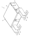
本発明の一実施形態の電磁継電器1は、図1に示すように、箱形の絶縁性のハウジング10と、このハウジング10にそれぞれ固定された第1固定接点側端子20、第1可動接点側端子30、第2固定接点側端子40、および、第2可動接点側端子50を備えている。
As shown in FIG. 1, the electromagnetic relay 1 according to the embodiment of the present invention includes a box-shaped
第1固定接点側端子20、第1可動接点側端子30、第2固定接点側端子40、および、第2可動接点側端子50は、それぞれ長手方向の中間部が屈曲した略L字の矩形板状で導電性を有している。また、第1固定接点側端子20および第1可動接点側端子30の間に、第2固定接点側端子40および第2可動接点側端子50が配置されていると共に、第1固定接点側端子20、第1可動接点側端子30、第2固定接点側端子40、および、第2可動接点側端子50のハウジング10の外部側の端部が、略一直線に並んでいる。
The first fixed
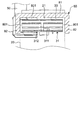
ハウジング10は、図1に示すように、略矩形箱状のベース11と略矩形板状のカバー12とで構成され、図2に示すように、その内部に収容部13を有している。すなわち、収容部13は、ベース11とカバー12とで覆われている。
As shown in FIG. 1, the
第1固定接点側端子20は、図2に示すように、ベース11の長手方向(すなわち、図2の左右方向)に対向する第1側壁111および第2側壁112のうちの第1側壁111に固定され、ハウジング10の外部から収容部13まで延びている。
As shown in FIG. 2, the first fixed
詳しくは、第1固定接点側端子20は、ハウジング10の外部をベース11の第1側壁111からベース11の短手方向に沿って第3側壁113から第4側壁114に向かう方向(すなわち、図2の下向き)に延びる外端子201と、外端子201の第1側壁111側の端部に接続され、ハウジング10の内部をベース11の第1側壁111からベース11の長手方向に沿って第2側壁112に向って延びる内端子202とで構成されている。内端子202の第4側壁114に対向する面には、第1固定接点部21が固定されている。第1固定接点部21は、ベース11の第1側壁111近傍に配置されている。
Specifically, the first fixed
第1可動接点側端子30は、図2に示すように、ベース11の第2側壁112の第1固定接点側端子20よりも第4側壁114側に固定され、第1固定接点側端子20に対して電気的に独立した状態でハウジング10の外部から収容部13まで延びている。
As shown in FIG. 2, the first movable
詳しくは、第1可動接点側端子30は、ハウジング10の外部をベース11の第2側壁112からベース11の短手方向に沿って第3側壁113から第4側壁114に向かう方向に延びる外端子301と、外端子301の第2側壁112側の端部に接続され、ハウジング10の内部をベース11の第2側壁112からベース11の長手方向に沿って第1側壁111に向って延びる内端子302とで構成されている。
Specifically, the first movable
図2に示すように、第1可動接点側端子30の内端子302の第1側壁111側の端部303には、第1可動接触片31が設けられている。第1可動接触片31は、収容部13に配置され、第1可動接点側端子30の端部303から第1固定接点側端子20に向かって延びている。また、第1可動接触片31は、一例として3枚の導電性を有する弾性変形可能な矩形の板部材をその板厚方向に重ねた板状積層体で構成され、その長手方向の一端部の板面が第1可動接点側端子30の内端子302の端部303の板面に接触した状態で固定されている。第1可動接触片31の長手方向の他端部のベース11の第3側壁113に対向する面には、第1可動接点部32が固定され、第1可動接触片31の第4側壁114に対向する面は、後述する第2可動接点側端子50の内端子502および第2可動接触片51に対向している。すなわち、第1可動接触片31は、その板厚方向(すなわち、ベース11の短手方向)に配置されかつ第1可動接点部32が設けられた第1面311と、第1可動接触片31の板厚方向における第1面311の反対側に配置されかつ第2可動接触片51および第2可動接点側端子50の内端子502に対向する第2面312とを有している。第1可動接点部32は、第1固定接点部21に対して対向するように配置され、第1可動接触片31が弾性変形することにより、第1固定接点部21に対してベース11の短手方向沿いに接触または開離するようになっている。
As shown in FIG. 2, a first
なお、第1面311における第1可動接触片31の第1可動接点部32と第1可動接点側端子30の端部303との間には、ベース11の第3側壁113に向かってU字状に突出した湾曲部33が設けられている。この湾曲部33により、第1可動接触片31が弾性変形したときの第1可動接触片31の撓み量を吸収および緩和し、円滑な動作特性を確保することができる。
A U-shape is formed between the first
図2に示すように、第1可動接点側端子30には、第1可動接触片31からの磁束を集める第1集磁片80と、第1可動接点側端子30の内端子302からの磁束を集める第1補助集磁片83とが設けられている。第1集磁片80は、一例として鉄で構成されており、図3に示すように、第1可動接触片31との間に隙間801を有するように配置されて第1可動接触片31の第1面311の少なくとも一部を覆っている。
As shown in FIG. 2, the first movable
詳しくは、第1集磁片80は、第1可動接触片31の第1面311の一部を覆う板状の横板部81と、第1面311および第2面312に交差(例えば、直交)しかつ第1可動接触片31の延在方向(すなわち、ベース11の短手方向)に延びる両側面の一部をそれぞれ覆う2つの板状の縦板部82とを有している。各縦板部82は、図3に示すように、横板部81の幅方向(すなわち、図3の左右方向)の両端部にそれぞれ接続され、ベース11の第4側壁114に向かって延びている。なお、図3では、ハウジング10を省略している。
Specifically, the first
また、第1補助集磁片83は、一例として鉄で構成された板状を有し、図2に示すように、横板部81の第2側壁112側の端部に接続され、第1可動接点側端子30の内端子302の第3側壁113に対向する面の一部を覆っている。
Further, the first auxiliary
第2固定接点側端子40は、図2に示すように、ベース11の第2側壁112の第1可動接点側端子30よりも第4側壁114側に固定され、第1固定接点側端子20および第1可動接点側端子30に対して電気的に独立した状態でハウジング10の外部から収容部13まで延びている。
As shown in FIG. 2, the second fixed
詳しくは、第2固定接点側端子40は、ハウジング10の外部をベース11の第2側壁112からベース11の短手方向に沿って第3側壁113から第4側壁114に向かう方向に延びる外端子401と、外端子401の第2側壁112側の端部に接続され、ハウジング10の内部をベース11の第2側壁112からベース11の長手方向に沿って第1側壁111に向かって延びる内端子402とで構成されている。内端子402の第3側壁113に対向する面には、第2固定接点部41が固定されている。第2固定接点部41は、ベース11の第2側壁112近傍に配置されている。
Specifically, the second fixed
第2可動接点側端子50は、図2に示すように、ベース11の第4側壁114の第1側壁111側の端部に固定され、第1固定接点側端子20、第1可動接点側端子30、および、第2固定接点側端子40に対して電気的に独立した状態でハウジング10の外部から収容部13まで延びている。
As shown in FIG. 2, the second movable
詳しくは、第1可動接点側端子30は、ハウジング10の外部をベース11の第4側壁114からベース11の短手方向に沿って第3側壁113から離れる方向に延びる外端子501と、外端子501の第4側壁112側の端部に接続され、ハウジング10の内部を第4側壁114からベース11の長手方向に沿って第1側壁111から第2側壁112に向かう方向に延びる内端子502とで構成されている。
Specifically, the first movable
図2に示すように、第2可動接点側端子50の内端子502の第2側壁111側の端部503には、第2可動接触片51が設けられている。第2可動接触片51は、第1可動接触片31の板厚方向(すなわち、ベース11の短手方向)で第1可動接触片31と隣接して収容部13に配置され、第2可動接点側端子50の端部503から第2固定接点側端子40に向かって延びている。また、第2可動接触片51は、一例として、第1可動接触片31と同様に、3枚の導電性を有する弾性変形可能な矩形の板部材をその板厚方向に重ねた板状積層体で構成され、その長手方向の一端部の板面が第2可動接点側端子50の内端子502の端部503の板面に接触した状態で固定されている。第2可動接触片51の長手方向の他端部のベース11の第4側壁114に対向する面には、第2可動接点部52が固定され、第2可動接触片51の第3側壁113に対向する面は、第1可動接点側端子30の内端子302および第1可動接触片31に対向している。すなわち、第2可動接触片51は、その板厚方向(すなわち、ベース11の短手方向)に配置されかつ第1可動接触片31および第1可動接点側端子30の内端子302に対向する第3面511と、第2可動接触片51の板厚方向における第3面511の反対側に配置されかつ第2可動接点部52が設けられた第4面512とを有している。第2可動接点部52は、第2固定接点部41に対して対向するように配置され、第2可動接触片51が弾性変形することにより、第2固定接点部41に対してベース11の短手方向沿いに接触または開離するようになっている。
As shown in FIG. 2, a second
なお、第4面512における第2可動接触片51の第2可動接点部52と第2可動接点側端子50の端部503との間には、ベース11の第4側壁114に向かってU字状に突出した湾曲部53が設けられている。この湾曲部53により、第2可動接触片51が弾性変形したときの第2可動接触片51の撓み量を吸収および緩和し、円滑な動作特性を確保することができる。
A U-shape is formed between the second
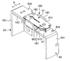
また、図2に示すように、第2可動接点側端子50には、第2可動接触片51および第2可動接点側端子50の内端子502からの磁束を集める第2集磁片180と、第2可動接点側端子50の内端子502からの磁束を集める第2補助集磁片183とが設けられている。第2集磁片180は、この集磁片80は、一例として鉄で構成されており、第2可動接触片51との間に隙間802(図4および図5に示す)を有するように配置されて第2可動接触片51の第4面512の少なくとも一部を覆っている。
Further, as shown in FIG. 2, the second movable
詳しくは、第2集磁片180は、第1集磁片80と同様の構成を有している。すなわち、第2集磁片180は、図4および図5に示すように、第2可動接触片51の第4面512の一部を覆う板状の横板部181と、第3面511および第4面512に交差(例えば、直交)しかつ第2可動接触片51の延在方向(すなわち、ベース11の短手方向)に延びる両側面の一部をそれぞれ覆う2つの板状の縦板部182とを有している。各縦板部182は、横板部181の幅方向(すなわち、図4のX方向)の両端部にそれぞれ接続され、図2に示すように、ベース11の第3側壁113に向かって延びている。
Specifically, the second
また、第2補助集磁片183は、一例として鉄で構成された板状を有し、図2に示すように、横板部81の第1側壁111側の端部に接続され、第2可動接点側端子50の内端子502の第4側壁114に対向する面の一部を覆っている。
Further, the second auxiliary
また、電磁継電器1は、図2に示すように、電磁石部60、回動ブロック70、絶縁性の第1可動部材90、および、絶縁性の第2可動部材100を有する駆動ユニット2を備えている。この駆動ユニット2は、ハウジング10の収容部13に収容されている。
Further, as shown in FIG. 2, the electromagnetic relay 1 includes a
電磁石部60は、図2に示すように、収容部13の第2側壁112に隣接する位置に配置されている。この電磁石部60は、ベース11の長手方向に延びる巻回中心軸CLを中心に巻回されたコイル61と、巻回中心軸CLが延びる電磁石部60の軸方向の両端からコイル61の外面に沿ってそれぞれ延びている板状の第1ヨーク62および板状の第2ヨーク63とを有している。第1ヨーク62および第2ヨーク63は、第1可動接触片31および第2可動接触片51と電磁石部60との間に配置されている。なお、図示していないが、電磁石部60にはコイル端子が設けられており、このコイル端子を介して、電磁石部60に2つの異なる方向の電流を選択的に供給可能になっている。
As shown in FIG. 2, the
第1ヨーク62は、図6に示すように、電磁石部60の軸方向における第1側壁111側の端部からベース11の第1側壁111に沿って第3側壁113から第4側壁114に向かう方向(すなわち、図6の下向き)に延びる接続部621と、この接続部621の電磁石部60から遠い方の先端部から巻回中心軸CLの延在方向に沿って第1側壁111から第2側壁112に向かう方向(すなわち、図6の右向き)に延びる吸着部622とで構成されている。
As shown in FIG. 6, the
第2ヨーク63は、図6に示すように、電磁石部60の軸方向における第2側壁112側の端部からベース11の第2側壁112に沿って第3側壁113から第4側壁114に向かう方向に延びる接続部631と、この接続部631の電磁石部60から遠い方の先端部から巻回中心軸CLの延在方向に沿って第2側壁112から第1側壁111に向かう方向(すなわち、図6の左向き)に延びる吸着部632とで構成されている。
As shown in FIG. 6, the
第1ヨーク62の吸着部622と第2ヨーク63の吸着部632とは、ベース11の高さ方向(すなわち、図6の紙面貫通方向)に沿った平面視において、巻回中心軸CLの延在方向に沿って延びる中心線が相互に一致するように配置されている。すなわち、第1ヨーク62の吸着部622の先端面と第2ヨーク63の吸着部632の先端面とは、相互に対向しており、その間に回動ブロック70を配置可能な回動ブロック配置空間64が設けられている。
The
図2に示すように、第1ヨーク62の吸着部622および第2ヨーク63の吸着部632には、ベース11の高さ方向に突出する突起部625、635がそれぞれ設けられている。各突起部625、635は、後述する固定板66の貫通孔661、662に嵌合可能になっている。
As shown in FIG. 2, the
回動ブロック70は、図6に示すように、ハウジング10のベース11に対して、ベース11の高さ方向に延びる回動軸71周りに回動可能に収容部13の回動ブロック配置空間64に配置されて、電磁石部60に供給された電流の方向に応じてハウジング10のベース11に対して異なる方向に回動する。詳しくは、回動ブロック70は、ブロックハウジング72(図2に示す)と、ブロックハウジング72の内部に設けられた永久磁石73と、この永久磁石73を挟んで対向するようにブロックハウジング72にそれぞれ固定された板状の第1鉄片74および板状の第2鉄片75とを有している。また、ブロックハウジング72の第4側壁114側かつ第1側壁111側の端部には、ベース11の第1側壁111に向かって延びる第1腕部721が設けられ、ブロックハウジング72の第4側壁114側かつ第2側壁112側の端部には、ベース11の第2側壁112に向かって延びる第2腕部722が設けられている。
As shown in FIG. 6, the rotating
第1鉄片74は、永久磁石73から第1ヨーク63に向かって突出する第1端部741と、永久磁石73から第2ヨーク63に向かって突出する第2端部742とを有しており、第1ヨーク62の吸着部622および第2ヨーク63の吸着部632に対して第3側壁113側に配置されている。
The
第2鉄片75は、永久磁石73から第1ヨーク63に向かって突出する第1端部751と、永久磁石73から第2ヨーク63に向かって突出する第2端部752とを有しており、第1ヨーク62の吸着部622および第2ヨーク63の吸着部632に対して第4側壁114側に配置されている。
The
第1鉄片74および第2鉄片75の第1端部741、751間には、第1ヨーク62が配置されて、第1鉄片74および第2鉄片75のいずれかの第1端部741、751が、回動ブロック70の回動方向で第1ヨーク62に接触するように構成されている。また、第1鉄片74および第2鉄片75の第2端部742、752間には、第2ヨーク63が配置されて、第1鉄片74および第2鉄片75のいずれかの第2端部742、752が、回動ブロック70の回動方向で第2ヨーク63に接触するように構成されている。
A
また、回動ブロック70は、ハウジング10のベース11と、電磁石部60の第1ヨーク62および第2ヨーク63に固定された固定板66とに回動可能に支持されている。固定板66は、図2に示すように、略矩形の板状で、長手方向の両端部にそれぞれ板厚方向に貫通する貫通孔661、662を有している。各貫通孔661、662は、それぞれ第1ヨーク62の突起部625および第2ヨーク63の突起部635に嵌合されている。また、固定板66の中央には、回動ブロック70の回動軸71を構成するブロックハウジング72の回動軸部76を挿入可能な軸孔部663が設けられている。
Further, the rotating
第1可動部材90は、図2に示すように、第1可動接触片31と回動ブロック70の第1腕部721とに接続されていると共に、回動ブロック70の回動方向に応じて移動して第1可動接触片31を弾性変形させて第1可動接点部32を第1固定接点部21に対して接触または開離させる。
As shown in FIG. 2, the first
詳しくは、第1可動部材90は、回動ブロック70の回動を第1可動接点部32が第1固定接点部21に対して接触または開離する接離方向(すなわち、ベース11の短手方向(図2の上下方向))の直線運動に変換可能であり、かつ、回動ブロック70の第1腕部721の先端部に回動ブロック70の回動を許容しつつ接続されていると共に、第1可動接触片31の延在方向における第1側壁111側の端部(すなわち、図2の左側の端部)に接続されている。すなわち、第1可動部材90は、回動ブロック70の回動により接離方向に移動して、第1可動接触片31の延在方向における第1側壁111側の端部を第1可動接点部32が第1固定接点部21に対して接触または開離する接離方向に移動させる。
Specifically, in the first
第2可動部材100は、図2に示すように、第2可動接触片51と回動ブロック70の第2腕部722とに接続されていると共に、回動ブロック70の回動方向に応じて移動して第2可動接触片51を弾性変形させて第2可動接点部52を第2固定接点部41に対して接触または開離させる。
As shown in FIG. 2, the second
詳しくは、第2可動部材100は、回動ブロック70の回動を第2可動接点部52が第2固定接点部41に対して接触または開離する接離方向(すなわち、図2の上下方向)の直線運動に変換可能であり、かつ、回動ブロック70の第2腕部722の先端部に回動ブロック70の回動を許容しつつ接続されていると共に、第2可動接触片51の延在方向における第2側壁112側の端部(すなわち、図2の右側の端部)に接続されている。すなわち、第2可動部材100は、回動ブロック70の回動により接離方向に移動して、第2可動接触片51の延在方向における第2側壁112側の端部を第2可動接点部52が第2固定接点部41に対して接触または開離する接離方向に移動させる。
Specifically, the second
前記電磁継電器1では、図2に示す動作状態(すなわち、回動ブロック70の第2鉄片75の第1端部751が、第1ヨーク62の吸着部622に接触し、回動ブロック70の第1鉄片74の第2端部742が、第2ヨーク63の吸着部632に接触して、第1可動接点部32と第1固定接点部21とが接触し、第2可動接点部52と第2固定接点部41とが接触した状態)の電磁継電器1の電磁石部60に所定方向(例えば、図2のA方向)の電流を供給して、回動ブロック70を回動ブロック70の回動軸71の延在方向から見て時計回りに回転させる。すると、回動ブロック70の回転に伴って、各腕部721、722も時計回りに回転し、第1可動部材90をベース11の第4側壁114に向かって移動させて、第1可動接点部32を第1固定接点部21から開離させると共に、第2可動部材100をベース11の第3側壁113に向かって移動させて、第2可動接点部52を第2固定接点部41から開離させる。これにより、電磁継電器1は、動作状態から復帰状態(すなわち、回動ブロック70の第1鉄片74の第1端部741が、第1ヨーク62の吸着部622に接触し、回動ブロック70の第2鉄片75の第2端部752が、第2ヨーク63の吸着部632に接触して、第1可動接点部32が第1固定接点部21から開離し、第2可動接点部52が第2固定接点部41から開離接触した状態)になる。
In the electromagnetic relay 1, the operating state shown in FIG. 2 (that is, the
動作状態の電磁継電器1では、第1可動接触片31に対して、接離方向に交差する第1可動接触片31の延在方向の一方側(例えば、図2の左側)に配置されている第1固定接点側端子20または第1可動接点側端子30(ここでは、第1固定接点側端子20)が、電流が供給される端子である。また、第2可動接触片51に対して、第1可動接触片31の延在方向の他方側(例えば、図2の右側)に配置されている第2固定接点側端子40または第2可動接点側端子50(ここでは、第2固定接点側端子40)が、電流が供給される端子である。すなわち、前記電磁継電器1では、通電時において、第1固定接点側端子20、第1可動接点側端子30、および、第1可動接触片31で構成される第1導電部3と、第2固定接点側端子40、第2可動接点側端子50、および、第2可動接触片51で構成される第2導電部4とに、相互に反対方向の電流が流れる(図2に、第1導電部3を流れる電流の方向を矢印Cで示し、第2導電部4を流れる電流の方向を矢印Dで示す)。
In the operating electromagnetic relay 1, the first
また、復帰状態の電磁継電器1の電磁石部60に所定方向とは異なる方向(例えば、図2のB方向)の電流を供給して、回動ブロック70を回動ブロック70の回動軸71の延在方向から見て反時計回りに回転させる。すると、回動ブロック70の回転に伴って、各腕部721、722も反時計回りに回転し、第1可動部材90をベース11の第3側壁113に向かって移動させて、第1可動接点部32を第1固定接点部21に対して接触させると共に、第2可動部材100をベース11の第4側壁114に向かって移動させて、第2可動接点部52を第2固定接点部41に対して接触させる。
Further, a current in a direction different from the predetermined direction (for example, the B direction in FIG. 2) is supplied to the
前記電磁継電器1では、第1可動接触片31および第2可動接触片51を備え、第1可動接触片31が、その板厚方向に交差する方向に延びかつ第1可動接点部32が設けられた第1面311と、その板厚方向において第1面311に相対しかつ第2可動接触片51および第2可動接点側端子50の内端子502に対向する第2面312とを有し、第2可動接触片51が、その板厚方向に交差する方向に延びかつ第1可動接触片31および第1可動接点側端子30の内端子302に対向する第3面511と、その板厚方向において第3面511に相対しかつ第2可動接点部52が設けられた第4面512とを有している。また、第1可動接触片31および第2可動接触片51を流れる電流が相互に反対方向に流れる。このため、通電時に、第1可動接触片31および第2可動接触片51に対して、各可動接点部32、52が対応する固定接点部21、41に接近する方向に電磁反発力が働き、各可動接点部32、52の対応する固定接点部21、41に対する接圧を高めることができる。その結果、各可動接点部32、52の対応する固定接点部21、41に対する接触信頼性を向上できる。
The electromagnetic relay 1 includes a first
また、第1可動接触片31との間に隙間を有するように配置されて第1可動接触片31の第1面311の少なくとも一部を覆い、第1可動接触片31からの磁束を集める第1集磁片80を備えている。この第1集磁片80により、第1可動接触片31からその周囲に広がる磁束を集め、第1可動接触片31と第2可動接触片51および第2可動接点側端子50との間に発生する電磁反発力を高めて、第1可動接点部32の第1固定接点部21に対する接圧を高めることができる。その結果、第1可動接点部32の第1固定接点部21に対する接触信頼性を向上できる。
Further, it is arranged so as to have a gap between the first
さらに、前記電磁継電器1では、第2可動接触片51との間に隙間を有するように配置されて第2可動接触片51の第4面512の少なくとも一部を覆い、第2可動接触片51からの磁束を集める第2集磁片180を備えている。この第2集磁片180により、第2可動接触片51からその周囲に広がる磁束を集め、第2可動接触片51と第1可動接触片31および第1可動接点側端子30との間に発生する電磁反発力を高めて、第2可動接点部52の第2固定接点部41に対する接圧を高めることができる。その結果、第2可動接点部52の第2固定接点部41に対する接触信頼性を向上できる。
Further, in the electromagnetic relay 1, the second
また、第1集磁片80が、第1可動接触片31の第1面311の少なくとも一部を覆う横板部81と、横板部81に接続され、第1面311および第2面312に交差しかつ第1可動接触片31の延在方向に延びる側面の少なくとも一部を覆い、第1可動接触片31からの磁束を集める縦板部82とを有している。このため、第1可動接触片31からその周囲に広がる磁束をより多く集めて、第1可動接点部32の第1固定接点部21に対する接圧を確実に高めることができる。その結果、第1可動接点部32の第1固定接点部21に対する接触信頼性を向上できる。
Further, the first magnetic
さらに、前記電磁継電器1では、第2可動接触片51の第4面512の少なくとも一部を覆う横板部181と、横板部181に接続され、第3面511および第4面512に交差しかつ第2可動接触片51の延在方向に延びる側面の少なくとも一部を覆い、第2可動接触片51からの磁束を集める縦板部182とを有している。このため、第2可動接触片51からその周囲に広がる磁束をより多く集めて、第2可動接点部52の第2固定接点部41に対する接圧を確実に高めることができる。その結果、第2可動接点部52の第2固定接点部41に対する接触信頼性を向上できる。
Further, in the electromagnetic relay 1, the
また、第1可動接点側端子30の少なくとも一部を覆って第1可動接点側端子30からの磁束を集める第1補助集磁片83をさらに備えている。この第1補助集磁片83により、第1可動接点側端子30の内端子302からその周囲に広がる磁束を集め、第1可動接点側端子30と第2可動接触片51および第2可動接点側端子50との間に発生する電磁反発力を高めて、第1可動接点部32の第1固定接点部21に対する接圧を高めることができる。その結果、第1可動接点部32の第1固定接点部21に対する接触信頼性を向上できる。
Further, a first auxiliary
さらに、第2可動接点側端子50の少なくとも一部を覆って第2可動接点側端子50からの磁束を集める第2補助集磁片183をさらに備えている。この第2補助集磁片183により、第2可動接点側端子50の内端子502からその周囲に広がる磁束を集め、第2可動接点側端子50と第1可動接触片31および第1可動接点側端子30との間に発生する電磁反発力を高めて、第2可動接点部52の第2固定接点部41に対する接圧を高めることができる。その結果、第2可動接点部52の第2固定接点部41に対する接触信頼性を向上できる。
Further, a second auxiliary
なお、前記電磁継電器1では、第1固定接点側端子20、第1可動接点側端子30、および、第1可動接触片31で構成された回路と、第2固定接点側端子40、第2可動接点側端子50、および、第2可動接触片51で構成された回路とが設けられているが、これに限らない。回路数は、複数であればよく、3以上の回路を有するように構成してもよい。
In the electromagnetic relay 1, the circuit composed of the first fixed
また、第1可動接触片31は、第2可動接点接触片51および第2可動接点側端子50の内端子502の少なくともいずれかに対向するように構成されていればよく、また、第2可動接触片51は、第1可動接触片31および第1可動接点端子30の内端子302の少なくともいずれかに対向するように構成されていればよい。
Further, the first
また、前記電磁継電器1では、第1可動接触片31に第1集磁片80を設け、第1可動接点側端子30に第1補助集磁片83を設けていると共に、第2可動接触片51に第2集磁片180を設け、第2可動接点側端子50に第2補助集磁片183を設けているが、これに限らない。第1集磁片80および第1補助集磁片83または第2集磁片180および第2補助集磁片183のいずれか一方のみを設けてもよい。また、可動接触片および可動接点側端子が3以上設けられている場合は、設けられている可動接触片および可動接点側端子のいずれか1組に集磁片および補助集磁片を設けてもよいし、設けられている可動接触片および可動接点側端子のいずれか複数組に集磁片および補助集磁片を設けてもよいし、設けられている可動接触片および可動接点側端子の全ての組に集磁片および補助集磁片を設けてもよい。さらに、第1集磁片80および/または第2集磁片180のみ設けてもよいし、第1補助集磁片83および/または第2補助集磁片183のみ設けてもよい。なお、第1集磁片80および/または第2集磁片180のみを設ける場合、例えば、ハウジング10に第1集磁片80および/または第2集磁片180を保持する保持部を設ければよい。
Further, in the electromagnetic relay 1, the first
また、第1集磁片80は、横板部81と縦板部82とを有する場合に限らない。例えば、図7に示すように、横板部81のみ有するように構成してもよい。なお、図示していないが、第2集磁片180についても同様に、横板部181のみ有するように構成してもよい。
Further, the first
また、図8に示すように、第1集磁片80は、横板部81および縦板部82に加えて、第1可動接触片31の第2面312の少なくとも一部を覆う補助横板部84を有してもよい。補助横板部84は、横板部81に対向するように配置され、その幅方向(図8のX方向)の両端部にそれぞれ各縦板部82が接続されている。すなわち、第1集磁片80は、横板部81、2つの縦板部82、および、補助横板部84により、第1可動接触片31の延在方向(すなわち、図8のY方向)における第1可動接触片31の周囲を隙間801を空けた状態で取り囲んでいる。これにより、第1可動接触片31からその周囲に広がる磁束をより多く集めて、第1可動接点部32の第1固定接点部21に対する接圧を確実に高めることができる。その結果、第1可動接点部32の第1固定接点部21に対する接触信頼性を向上できる。なお、図示していないが、第2集磁片180についても同様に、補助横板部のみ有するように構成してもよい。
Further, as shown in FIG. 8, the first
また、第1補助集磁片83により、第1可動接点側端子30の内端子302の延在方向における第1可動接点側端子30の周囲を取り囲むように構成してもよいし、第2補助集磁片183により、第2可動接点側端子50の延在方向における第2可動接点側端子50の周囲を取り囲むように構成してもよい。これにより、第1可動接点側端子30および/または第2可動接点側端子50からその周囲に広がる磁束をより多く集めて、第1可動接点部32の第1固定接点部21に対する接圧および/または第2可動接点部52の第2固定接点部41に対する接圧を確実に高めることができる。その結果、第1可動接点部32の第1固定接点部21に対する接触信頼性および/または第2可動接点部52の第2固定接点部41に対する接触信頼性を向上できる。なお、第1補助集磁片83および第2補助集磁片183は、第1可動接点側端子30および第2可動接点側端子50に接触するように設けてもよいし、隙間を空けて設けてもよい。
Further, the first auxiliary
以上、図面を参照して本発明における種々の実施形態を詳細に説明したが、最後に、本発明の種々の態様について説明する。 Although various embodiments of the present invention have been described in detail with reference to the drawings, finally, various aspects of the present invention will be described.
本発明の第1態様の電磁継電器は、
内部に収容部を有する箱形の絶縁性のハウジングと、
前記ハウジングに固定され、前記ハウジングの外部から前記収容部まで延びていると共に、前記収容部に位置する第1固定接点部を有する板状の第1固定接点側端子と、
前記ハウジングに固定され、前記ハウジングの外部から前記収容部まで延びていると共に、前記第1固定接点側端子に対して電気的に独立して配置されている板状の第1可動接点側端子と、
前記収容部に配置され、前記第1可動接点側端子から前記第1固定接点側端子に向かって延びかつ前記第1可動接点側端子と電気的に接続されていると共に、前記第1固定接点部に対向する第1可動接点部を有し、前記第1可動接点部が前記第1固定接点部に対して接触または開離する接離方向に弾性変形する板状の第1可動接触片と、
前記ハウジングに固定され、前記ハウジングの外部から前記収容部まで延びかつ前記第1固定接点側端子および前記第1可動接点側端子に対して電気的に独立して配置されていると共に、前記収容部に位置する第2固定接点部を有する板状の第2固定接点側端子と、
前記ハウジングに固定され、前記ハウジングの外部から前記収容部まで延びていると共に、前記第1固定接点側端子、前記第1可動接点側端子、および、前記第2固定接点側端子に対して電気的に独立して配置されている板状の第2可動接点側端子と、
前記第1可動接触片の板厚方向で前記第1可動接触片と隣接して前記収容部に配置され、前記第2可動接点側端子から前記第2固定接点側端子に向かって延びかつ前記第2可動接点側端子と電気的に接続されていると共に、前記第2固定接点部に対向する第2可動接点部を有し、前記第2可動接点部が前記第2固定接点部に対して前記接離方向に弾性変形する板状の第2可動接触片と、
を備え、
前記第1可動接触片は、その板厚方向に交差する方向に延びかつ前記第1可動接点部が設けられた第1面と、前記第1面に相対しかつ前記第2可動接触片および第2可動接点側端子の少なくともいずれかに対向する第2面とを有し、
前記第2可動接触片は、その板厚方向に交差する方向に延びかつ前記第1可動接触片および前記第1可動接点側端子の少なくともいずれかに対向する第3面と、前記第3面に相対しかつ前記第2可動接点部が設けられた第4面とを有しており、
前記第1可動接触片に対して、前記接離方向に交差する前記第1可動接触片の延在方向の一方側に配置されている前記第1固定接点側端子または前記第1可動接点側端子が、電流が供給される端子であると共に、前記第2可動接触片に対して、前記第1可動接触片の延在方向の他方側に配置されている前記第2固定接点側端子または前記第2可動接点側端子が、電流が供給される端子である。
The electromagnetic relay according to the first aspect of the present invention is
A box-shaped insulating housing with an internal housing,
A plate-shaped first fixed contact side terminal that is fixed to the housing, extends from the outside of the housing to the housing portion, and has a first fixed contact portion located in the housing portion.
A plate-shaped first movable contact side terminal that is fixed to the housing, extends from the outside of the housing to the housing portion, and is electrically arranged independently of the first fixed contact side terminal. ,
The first fixed contact portion is arranged in the accommodating portion, extends from the first movable contact side terminal toward the first fixed contact side terminal, and is electrically connected to the first movable contact side terminal. A plate-shaped first movable contact piece having a first movable contact portion facing the surface and elastically deforming in the contact / separation direction in which the first movable contact portion contacts or opens with respect to the first fixed contact portion.
It is fixed to the housing, extends from the outside of the housing to the housing portion, and is electrically and independently arranged with respect to the first fixed contact side terminal and the first movable contact side terminal, and the housing portion. A plate-shaped second fixed contact side terminal having a second fixed contact portion located at
It is fixed to the housing, extends from the outside of the housing to the housing portion, and is electrically connected to the first fixed contact side terminal, the first movable contact side terminal, and the second fixed contact side terminal. The plate-shaped second movable contact side terminal, which is independently arranged in the housing,
The first movable contact piece is arranged in the accommodating portion adjacent to the first movable contact piece in the plate thickness direction, extends from the second movable contact side terminal toward the second fixed contact side terminal, and is said to be the first. 2 It is electrically connected to the movable contact side terminal and has a second movable contact portion facing the second fixed contact portion, and the second movable contact portion has the second movable contact portion with respect to the second fixed contact portion. A plate-shaped second movable contact piece that elastically deforms in the contact / separation direction,
With
The first movable contact piece extends in a direction intersecting the plate thickness direction and is provided with the first movable contact portion, and the second movable contact piece and the first movable contact piece are opposed to the first surface and are provided with the first movable contact portion. 2 It has a second surface facing at least one of the movable contact side terminals, and has
The second movable contact piece extends on a third surface extending in a direction intersecting the plate thickness direction and facing at least one of the first movable contact piece and the first movable contact side terminal, and the third surface. It has a fourth surface that faces each other and is provided with the second movable contact portion.
The first fixed contact side terminal or the first movable contact side terminal arranged on one side of the first movable contact piece in the extending direction of the first movable contact piece intersecting with the first movable contact piece. Is a terminal to which an electric current is supplied, and the second fixed contact side terminal or the first fixed contact side terminal arranged on the other side of the first movable contact piece in the extending direction with respect to the second movable contact piece. 2 The movable contact side terminal is a terminal to which an electric current is supplied.
第1態様の電磁継電器によれば、第1可動接触片および第2可動接触片を備え、第1可動接触片が、その板厚方向に交差する方向に延びかつ第1可動接点部が設けられた第1面と、第1面に相対しかつ第2可動接触片および第2可動接点側端子の少なくともいずれかに対向する第2面とを有し、第2可動接触片が、その板厚方向に交差する方向に延びかつ第1可動接触片および第1可動接点側端子の少なくともいずれかに対向する第3面と、第3面に相対しかつ第2可動接点部が設けられた第4面とを有している。また、第1可動接触片および第2可動接触片を流れる電流の向きが相互に異なっている。このため、通電時に、第1可動接触片および第2可動接触片に対して、各可動接点部が対応する固定接点部に接近する方向に電磁反発力が働き、各可動接点部の対応する固定接点部に対する接圧を高めることができる。その結果、各可動接点部の対応する固定接点部に対する接触信頼性を向上できる。 According to the electromagnetic relay of the first aspect, the first movable contact piece and the second movable contact piece are provided, the first movable contact piece extends in a direction intersecting the plate thickness direction, and the first movable contact portion is provided. It has a first surface and a second surface facing the first surface and facing at least one of a second movable contact piece and a second movable contact side terminal, and the second movable contact piece has a plate thickness thereof. A third surface extending in a direction intersecting the directions and facing at least one of the first movable contact piece and the first movable contact side terminal, and a fourth surface facing the third surface and provided with a second movable contact portion. Has a surface. Further, the directions of the currents flowing through the first movable contact piece and the second movable contact piece are different from each other. Therefore, when energized, an electromagnetic repulsive force acts on the first movable contact piece and the second movable contact piece in the direction in which each movable contact portion approaches the corresponding fixed contact portion, and the corresponding fixing of each movable contact portion. The contact pressure with respect to the contact portion can be increased. As a result, the contact reliability of each movable contact portion with respect to the corresponding fixed contact portion can be improved.
本発明の第2態様の電磁継電器は、
前記収容部に設けられ、前記第1可動接触片との間に隙間を有するように配置されて前記第1可動接触片の前記第1面の少なくとも一部を覆い、前記第1可動接触片からの磁束を集める集磁片をさらに備える。
The electromagnetic relay according to the second aspect of the present invention is
It is provided in the accommodating portion and is arranged so as to have a gap between the first movable contact piece and the first movable contact piece so as to cover at least a part of the first surface of the first movable contact piece. It is further equipped with a magnetic flux collecting piece that collects the magnetic flux of.
第2態様の電磁継電器によれば、集磁片により、第1可動接触片からその周囲に広がる磁束を集め、第1可動接触片と第2可動接触片および第2可動接点側端子との間に発生する電磁反発力を高めて、第1可動接点部の第1固定接点部に対する接圧を高めることができる。その結果、第1可動接点部の第1固定接点部に対する接触信頼性を向上できる。 According to the electromagnetic relay of the second aspect, the magnetic collecting piece collects the magnetic flux spreading from the first movable contact piece to the surroundings, and between the first movable contact piece, the second movable contact piece, and the second movable contact side terminal. It is possible to increase the electromagnetic repulsive force generated in the first movable contact portion to increase the contact pressure of the first movable contact portion with respect to the first fixed contact portion. As a result, the contact reliability of the first movable contact portion with respect to the first fixed contact portion can be improved.
本発明の第3態様の電磁継電器は、
前記集磁片が、
前記第1可動接触片の前記第1面の少なくとも一部を覆う横板部と、
前記横板部に接続され、前記第1面および前記第2面に交差しかつ前記第1可動接触片の延在方向に延びる側面の少なくとも一部を覆い、前記第1可動接触片からの磁束を集める縦板部と
を有している。
The electromagnetic relay according to the third aspect of the present invention is
The magnetic collecting piece
A horizontal plate portion that covers at least a part of the first surface of the first movable contact piece, and
The magnetic flux from the first movable contact piece, which is connected to the horizontal plate portion, intersects the first surface and the second surface, and covers at least a part of the side surface extending in the extending direction of the first movable contact piece. It has a vertical plate part to collect the magnetic flux.
第3態様の電磁継電器によれば、第1可動接触片からその周囲に広がる磁束をより多く集めて、第1可動接点部の第1固定接点部に対する接圧を確実に高めることができる。その結果、第1可動接点部の第1固定接点部に対する接触信頼性を向上できる。 According to the electromagnetic relay of the third aspect, it is possible to collect more magnetic flux spreading around the first movable contact piece and surely increase the contact pressure of the first movable contact portion with respect to the first fixed contact portion. As a result, the contact reliability of the first movable contact portion with respect to the first fixed contact portion can be improved.
本発明の第4態様の電磁継電器は、
前記集磁片が、前記縦板部に接続され、前記第1可動接触片の前記第2面の少なくとも一部を覆い、前記第1可動接触片からの磁束を集める補助横板部を有している。
The electromagnetic relay according to the fourth aspect of the present invention is
The magnetic collecting piece is connected to the vertical plate portion, covers at least a part of the second surface of the first movable contact piece, and has an auxiliary horizontal plate portion that collects magnetic flux from the first movable contact piece. ing.
第4態様の電磁継電器によれば、第1可動接触片31が、横板部、縦板部、および、補助横板部により、取り囲まれている。これにより、第1可動接触片からその周囲に広がる磁束をより多く集めて、第1可動接点部の第1固定接点部に対する接圧を確実に高めることができる。その結果、第1可動接点部の第1固定接点部に対する接触信頼性を向上できる。
According to the electromagnetic relay of the fourth aspect, the first
本発明の第5態様の電磁継電器は、
前記第1可動接点側端子の少なくとも一部を覆って前記第1可動接点側端子からの磁束を集める補助集磁片をさらに備える。
The electromagnetic relay according to the fifth aspect of the present invention is
An auxiliary magnetic collecting piece that covers at least a part of the first movable contact side terminal and collects magnetic flux from the first movable contact side terminal is further provided.
第5態様の電磁継電器によれば、補助集磁片により、第1可動接点側端子からその周囲に広がる磁束を集め、第1可動接点側端子と第2可動接触片および第2可動接点側端子との間に発生する電磁反発力を高めて、第1可動接点部の第1固定接点部に対する接圧を高めることができる。その結果、第1可動接点部の第1固定接点部に対する接触信頼性を向上できる。 According to the electromagnetic relay of the fifth aspect, the auxiliary magnetic collecting piece collects the magnetic flux spreading from the first movable contact side terminal to the surroundings, and the first movable contact side terminal, the second movable contact piece, and the second movable contact side terminal. It is possible to increase the electromagnetic repulsive force generated between the first movable contact portion and the first movable contact portion to increase the contact pressure with respect to the first fixed contact portion. As a result, the contact reliability of the first movable contact portion with respect to the first fixed contact portion can be improved.
なお、前記様々な実施形態または変形例のうちの任意の実施形態または変形例を適宜組み合わせることにより、それぞれの有する効果を奏するようにすることができる。また、実施形態同士の組み合わせまたは実施例同士の組み合わせまたは実施形態と実施例との組み合わせが可能であると共に、異なる実施形態または実施例の中の特徴同士の組み合わせも可能である。 By appropriately combining any of the various embodiments or modifications, the effects of each can be achieved. In addition, it is possible to combine embodiments or examples, or between embodiments and examples, and it is also possible to combine features in different embodiments or examples.
本発明の電磁継電器は、例えば、スマートメータに適用できる。 The electromagnetic relay of the present invention can be applied to, for example, a smart meter.
1 電磁継電器
2 駆動ユニット
10 ハウジング
11 ベース
111 第1側壁
112 第2側壁
113 第3側壁
114 第4側壁
12 カバー
13 収容部
20 第1固定接点側端子
201 外端子
202 内端子
21 第1固定接点部
30 第1可動接点側端子
301 外端子
302 内端子
303 端部
31 第1可動接触片
32 第1可動接点部
33 湾曲部
40 第2固定接点側端子
401 外端子
402 内端子
41 第2固定接点部
50 第2可動接点側端子
501 外端子
502 内端子
503 端部
51 第2可動接触片
52 第2可動接点部
53 湾曲部
60 電磁石部
61 コイル
62 第1ヨーク
621 接続部
622 吸着部
63 第2ヨーク
631 接続部
632 吸着部
64 回動ブロック配置空間
66 固定板
70 回動ブロック
71 回動軸
72 ブロックハウジング
721 第1腕部
722 第2腕部
73 永久磁石
74 第1鉄片
741 第1端部
742 第2端部
75 第2鉄片
751 第1端部
752 第2端部
80 第1集磁片
81 横板部
82 縦板部
83 第1補助集磁片
84 補助横板部
180 第2集磁片
181 横板部
182 縦板部
183 第2補助集磁片
90 第1可動部材
100 第2可動部材
CL 巻回中心軸
1
Claims (5)
前記ハウジングに固定され、前記ハウジングの外部から前記収容部まで延びていると共に、前記収容部に位置する第1固定接点部を有する板状の第1固定接点側端子と、
前記ハウジングに固定され、前記ハウジングの外部から前記収容部まで延びていると共に、前記第1固定接点側端子に対して電気的に独立して配置されている板状の第1可動接点側端子と、
前記収容部に配置され、前記第1可動接点側端子から前記第1固定接点側端子に向かって延びかつ前記第1可動接点側端子と電気的に接続されていると共に、前記第1固定接点部に対向する第1可動接点部を有し、前記第1可動接点部が前記第1固定接点部に対して接触または開離する接離方向に弾性変形する板状の第1可動接触片と、
前記ハウジングに固定され、前記ハウジングの外部から前記収容部まで延びかつ前記第1固定接点側端子および前記第1可動接点側端子に対して電気的に独立して配置されていると共に、前記収容部に位置する第2固定接点部を有する板状の第2固定接点側端子と、
前記ハウジングに固定され、前記ハウジングの外部から前記収容部まで延びていると共に、前記第1固定接点側端子、前記第1可動接点側端子、および、前記第2固定接点側端子に対して電気的に独立して配置されている板状の第2可動接点側端子と、
前記第1可動接触片の板厚方向で前記第1可動接触片と隣接して前記収容部に配置され、前記第2可動接点側端子から前記第2固定接点側端子に向かって延びかつ前記第2可動接点側端子と電気的に接続されていると共に、前記第2固定接点部に対向する第2可動接点部を有し、前記第2可動接点部が前記第2固定接点部に対して前記接離方向に弾性変形する板状の第2可動接触片と、
を備え、
前記第1可動接触片は、その板厚方向に交差する方向に延びかつ前記第1可動接点部が設けられた第1面と、前記第1面に相対しかつ前記第2可動接触片および第2可動接点側端子の少なくともいずれかに対向する第2面とを有し、
前記第2可動接触片は、その板厚方向に交差する方向に延びかつ前記第1可動接触片および前記第1可動接点側端子の少なくともいずれかに対向する第3面と、前記第3面に相対しかつ前記第2可動接点部が設けられた第4面とを有しており、
前記第1可動接触片に対して、前記接離方向に交差する前記第1可動接触片の延在方向の一方側に配置されている前記第1固定接点側端子または前記第1可動接点側端子が、電流が供給される端子であると共に、前記第2可動接触片に対して、前記第1可動接触片の延在方向の他方側に配置されている前記第2固定接点側端子または前記第2可動接点側端子が、電流が供給される端子であり、
前記第1固定接点側端子、前記第1可動接点側端子、および、前記第1可動接触片で構成される第1導電部と、前記第2固定接点側端子、前記第2可動接点側端子、および、前記第2可動接触片で構成される第2導電部とに、相互に反対方向の電流が流れる、電磁継電器。 A box-shaped insulating housing with an internal housing,
A plate-shaped first fixed contact side terminal that is fixed to the housing, extends from the outside of the housing to the housing portion, and has a first fixed contact portion located in the housing portion.
A plate-shaped first movable contact side terminal that is fixed to the housing, extends from the outside of the housing to the housing portion, and is electrically arranged independently of the first fixed contact side terminal. ,
The first fixed contact portion is arranged in the accommodating portion, extends from the first movable contact side terminal toward the first fixed contact side terminal, and is electrically connected to the first movable contact side terminal. A plate-shaped first movable contact piece having a first movable contact portion facing the surface and elastically deforming in the contact / separation direction in which the first movable contact portion contacts or opens with respect to the first fixed contact portion.
It is fixed to the housing, extends from the outside of the housing to the housing portion, and is electrically and independently arranged with respect to the first fixed contact side terminal and the first movable contact side terminal, and the housing portion. A plate-shaped second fixed contact side terminal having a second fixed contact portion located at
It is fixed to the housing, extends from the outside of the housing to the housing portion, and is electrically connected to the first fixed contact side terminal, the first movable contact side terminal, and the second fixed contact side terminal. The plate-shaped second movable contact side terminal, which is independently arranged in the housing,
The first movable contact piece is arranged in the accommodating portion adjacent to the first movable contact piece in the plate thickness direction, extends from the second movable contact side terminal toward the second fixed contact side terminal, and is said to be the first. 2 It is electrically connected to the movable contact side terminal and has a second movable contact portion facing the second fixed contact portion, and the second movable contact portion has the second movable contact portion with respect to the second fixed contact portion. A plate-shaped second movable contact piece that elastically deforms in the contact / separation direction,
With
The first movable contact piece extends in a direction intersecting the plate thickness direction and is provided with the first movable contact portion, and the second movable contact piece and the first movable contact piece are opposed to the first surface and are provided with the first movable contact portion. 2 It has a second surface facing at least one of the movable contact side terminals, and has
The second movable contact piece extends on a third surface extending in a direction intersecting the plate thickness direction and facing at least one of the first movable contact piece and the first movable contact side terminal, and the third surface. It has a fourth surface that faces each other and is provided with the second movable contact portion.
The first fixed contact side terminal or the first movable contact side terminal arranged on one side of the first movable contact piece in the extending direction of the first movable contact piece intersecting with the first movable contact piece. Is a terminal to which an electric current is supplied, and the second fixed contact side terminal or the first fixed contact side terminal arranged on the other side of the first movable contact piece in the extending direction with respect to the second movable contact piece. 2 movable contact side terminal, Ri Ah at terminal current is supplied,
The first conductive portion composed of the first fixed contact side terminal, the first movable contact side terminal, and the first movable contact piece, the second fixed contact side terminal, and the second movable contact side terminal. and, wherein the second conductive portion composed of the second movable contact piece, opposite the direction of the current Ru flows mutually electromagnetic relay.
前記第1可動接触片の前記第1面の少なくとも一部を覆う横板部と、
前記横板部に接続され、前記第1面および前記第2面に交差しかつ前記第1可動接触片の延在方向に延びる側面の少なくとも一部を覆い、前記第1可動接触片からの磁束を集める縦板部と
を有している、請求項2の電磁継電器。 The magnetic collecting piece
A horizontal plate portion that covers at least a part of the first surface of the first movable contact piece, and
The magnetic flux from the first movable contact piece, which is connected to the horizontal plate portion, intersects the first surface and the second surface, and covers at least a part of the side surface extending in the extending direction of the first movable contact piece. The electromagnetic relay according to claim 2, which has a vertical plate portion for collecting the magnetic flux.
Priority Applications (2)
| Application Number | Priority Date | Filing Date | Title |
|---|---|---|---|
| JP2017151945A JP6922534B2 (en) | 2017-08-04 | 2017-08-04 | Electromagnetic relay |
| PCT/JP2018/028085 WO2019026756A1 (en) | 2017-08-04 | 2018-07-26 | Electromagnetic relay |
Applications Claiming Priority (1)
| Application Number | Priority Date | Filing Date | Title |
|---|---|---|---|
| JP2017151945A JP6922534B2 (en) | 2017-08-04 | 2017-08-04 | Electromagnetic relay |
Publications (3)
| Publication Number | Publication Date |
|---|---|
| JP2019032947A JP2019032947A (en) | 2019-02-28 |
| JP2019032947A5 JP2019032947A5 (en) | 2020-04-09 |
| JP6922534B2 true JP6922534B2 (en) | 2021-08-18 |
Family
ID=65233510
Family Applications (1)
| Application Number | Title | Priority Date | Filing Date |
|---|---|---|---|
| JP2017151945A Active JP6922534B2 (en) | 2017-08-04 | 2017-08-04 | Electromagnetic relay |
Country Status (2)
| Country | Link |
|---|---|
| JP (1) | JP6922534B2 (en) |
| WO (1) | WO2019026756A1 (en) |
Families Citing this family (1)
| Publication number | Priority date | Publication date | Assignee | Title |
|---|---|---|---|---|
| DE102019117802A1 (en) * | 2019-07-02 | 2021-01-07 | Johnson Electric Germany GmbH & Co. KG | Switching contact system of a switching device operated by electrical current |
Family Cites Families (5)
| Publication number | Priority date | Publication date | Assignee | Title |
|---|---|---|---|---|
| JP2006032131A (en) * | 2004-07-16 | 2006-02-02 | Matsushita Electric Works Ltd | Contact mechanism and power relay using the same |
| CN102405507B (en) * | 2009-02-04 | 2015-06-03 | Clodi公司 | Electromagnetic relay assembly |
| US8514040B2 (en) * | 2011-02-11 | 2013-08-20 | Clodi, L.L.C. | Bi-stable electromagnetic relay with x-drive motor |
| JP5838920B2 (en) * | 2011-07-18 | 2016-01-06 | アンデン株式会社 | relay |
| JP5720729B2 (en) * | 2013-07-12 | 2015-05-20 | オムロン株式会社 | Contact mechanism |
-
2017
- 2017-08-04 JP JP2017151945A patent/JP6922534B2/en active Active
-
2018
- 2018-07-26 WO PCT/JP2018/028085 patent/WO2019026756A1/en active Application Filing
Also Published As
| Publication number | Publication date |
|---|---|
| WO2019026756A1 (en) | 2019-02-07 |
| JP2019032947A (en) | 2019-02-28 |
Similar Documents
| Publication | Publication Date | Title |
|---|---|---|
| CN102891039B (en) | Relay | |
| CN102891040B (en) | Relay | |
| US9305718B2 (en) | Electromagnetic relay | |
| JP5991778B2 (en) | Electromagnetic relay | |
| CN109727817A (en) | Electromagnetic relay | |
| JP5720729B2 (en) | Contact mechanism | |
| JP6132043B1 (en) | Power switchgear | |
| JP6922534B2 (en) | Electromagnetic relay | |
| JP5549642B2 (en) | relay | |
| CN109427508B (en) | Electromagnetic relay | |
| JP6897408B2 (en) | Electromagnetic relay | |
| JP6011267B2 (en) | Electromagnetic relay | |
| WO2019087927A1 (en) | Electromagnetic relay and electromagnetic device | |
| JP6897409B2 (en) | Electromagnetic relay | |
| JP5853223B2 (en) | Relay device | |
| WO2018043159A1 (en) | Electromagnetic relay | |
| JP2019032944A (en) | Magnetic relay and smart meter | |
| WO2018159060A1 (en) | Electromagnetic relay and smart meter | |
| WO2016157558A1 (en) | Electromagnetic relay | |
| JP6830259B2 (en) | Electromagnetic relay | |
| JP6726156B2 (en) | Electromagnetic relay | |
| JP6948613B2 (en) | Contact devices and electromagnetic relays | |
| JP5930095B1 (en) | Electromagnetic drive mechanism and electromagnetic relay having the same | |
| JP2021190341A (en) | Contact device and electromagnetic relay | |
| EP2854150A1 (en) | Electromechanical relay |
Legal Events
| Date | Code | Title | Description |
|---|---|---|---|
| A521 | Written amendment |
Free format text: JAPANESE INTERMEDIATE CODE: A523 Effective date: 20200302 |
|
| A621 | Written request for application examination |
Free format text: JAPANESE INTERMEDIATE CODE: A621 Effective date: 20200302 |
|
| A131 | Notification of reasons for refusal |
Free format text: JAPANESE INTERMEDIATE CODE: A131 Effective date: 20210406 |
|
| A521 | Written amendment |
Free format text: JAPANESE INTERMEDIATE CODE: A523 Effective date: 20210531 |
|
| TRDD | Decision of grant or rejection written | ||
| A01 | Written decision to grant a patent or to grant a registration (utility model) |
Free format text: JAPANESE INTERMEDIATE CODE: A01 Effective date: 20210629 |
|
| A61 | First payment of annual fees (during grant procedure) |
Free format text: JAPANESE INTERMEDIATE CODE: A61 Effective date: 20210712 |
|
| R150 | Certificate of patent or registration of utility model |
Ref document number: 6922534 Country of ref document: JP Free format text: JAPANESE INTERMEDIATE CODE: R150 |