EP2673460B1 - Completion assembly - Google Patents
Completion assembly Download PDFInfo
- Publication number
- EP2673460B1 EP2673460B1 EP12744653.2A EP12744653A EP2673460B1 EP 2673460 B1 EP2673460 B1 EP 2673460B1 EP 12744653 A EP12744653 A EP 12744653A EP 2673460 B1 EP2673460 B1 EP 2673460B1
- Authority
- EP
- European Patent Office
- Prior art keywords
- valve
- completion assembly
- assembly
- lower completion
- well
- Prior art date
- Legal status (The legal status is an assumption and is not a legal conclusion. Google has not performed a legal analysis and makes no representation as to the accuracy of the status listed.)
- Active
Links
- 238000002955 isolation Methods 0.000 claims description 53
- 238000012856 packing Methods 0.000 claims description 45
- 239000012530 fluid Substances 0.000 claims description 41
- 238000004891 communication Methods 0.000 claims description 30
- 238000004519 manufacturing process Methods 0.000 claims description 25
- 239000002002 slurry Substances 0.000 claims description 17
- 238000000034 method Methods 0.000 claims description 15
- 238000009434 installation Methods 0.000 claims description 7
- 239000000835 fiber Substances 0.000 claims 1
- 230000002093 peripheral effect Effects 0.000 claims 1
- 230000007704 transition Effects 0.000 claims 1
- 238000010586 diagram Methods 0.000 description 15
- 230000015572 biosynthetic process Effects 0.000 description 14
- 238000005755 formation reaction Methods 0.000 description 14
- 230000000712 assembly Effects 0.000 description 11
- 238000000429 assembly Methods 0.000 description 11
- 230000001939 inductive effect Effects 0.000 description 11
- 230000001105 regulatory effect Effects 0.000 description 6
- 239000004576 sand Substances 0.000 description 5
- 239000004215 Carbon black (E152) Substances 0.000 description 4
- 230000001276 controlling effect Effects 0.000 description 4
- 229930195733 hydrocarbon Natural products 0.000 description 4
- 150000002430 hydrocarbons Chemical class 0.000 description 4
- 230000000638 stimulation Effects 0.000 description 4
- 230000008602 contraction Effects 0.000 description 3
- 230000008878 coupling Effects 0.000 description 3
- 238000010168 coupling process Methods 0.000 description 3
- 238000005859 coupling reaction Methods 0.000 description 3
- 238000013461 design Methods 0.000 description 3
- 238000012986 modification Methods 0.000 description 3
- 230000004048 modification Effects 0.000 description 3
- 230000003287 optical effect Effects 0.000 description 3
- 230000008901 benefit Effects 0.000 description 2
- 238000001914 filtration Methods 0.000 description 2
- 230000013011 mating Effects 0.000 description 2
- VNWKTOKETHGBQD-UHFFFAOYSA-N methane Chemical compound C VNWKTOKETHGBQD-UHFFFAOYSA-N 0.000 description 2
- 238000007789 sealing Methods 0.000 description 2
- 239000000758 substrate Substances 0.000 description 2
- 230000000903 blocking effect Effects 0.000 description 1
- 230000000295 complement effect Effects 0.000 description 1
- 239000007789 gas Substances 0.000 description 1
- 238000005259 measurement Methods 0.000 description 1
- 230000007246 mechanism Effects 0.000 description 1
- 238000012544 monitoring process Methods 0.000 description 1
- 239000003345 natural gas Substances 0.000 description 1
- 239000006187 pill Substances 0.000 description 1
- 230000001681 protective effect Effects 0.000 description 1
- 230000008961 swelling Effects 0.000 description 1
- 238000013519 translation Methods 0.000 description 1
- 238000011144 upstream manufacturing Methods 0.000 description 1
Images


Classifications
-
- E—FIXED CONSTRUCTIONS
- E21—EARTH DRILLING; MINING
- E21B—EARTH DRILLING, e.g. DEEP DRILLING; OBTAINING OIL, GAS, WATER, SOLUBLE OR MELTABLE MATERIALS OR A SLURRY OF MINERALS FROM WELLS
- E21B43/00—Methods or apparatus for obtaining oil, gas, water, soluble or meltable materials or a slurry of minerals from wells
- E21B43/02—Subsoil filtering
- E21B43/04—Gravelling of wells
-
- E—FIXED CONSTRUCTIONS
- E21—EARTH DRILLING; MINING
- E21B—EARTH DRILLING, e.g. DEEP DRILLING; OBTAINING OIL, GAS, WATER, SOLUBLE OR MELTABLE MATERIALS OR A SLURRY OF MINERALS FROM WELLS
- E21B43/00—Methods or apparatus for obtaining oil, gas, water, soluble or meltable materials or a slurry of minerals from wells
- E21B43/02—Subsoil filtering
- E21B43/08—Screens or liners
Definitions
- a wellbore For purposes of forming a well to extract a hydrocarbon-based fluid (oil or natural gas) from a hydrocarbon-bearing geological formation, a wellbore is first drilled into the formation and completion equipment, which typically includes a complex system of tubes and valves, is installed in the wellbore to regulate the production of well fluid from the well.
- completion equipment typically includes a complex system of tubes and valves
- the completion equipment may include sand control equipment, such as screens and filtering media, and a production tubing string to communicate well fluid to the Earth surface.
- Installing the completion equipment, as well as conducting downhole operations associated with completing the well, such as gravel packing and/or fracturing operations, may involve multiple runs, or trips, into the well. In general, each trip into the well may add to the cost and complexity associated with completing the well.
- the present invention resides in a method as defined in claim 1.
- Preferred embodiments are defined in claims 2 to 5.
- the present invention resides in a system as defined in claim 6.
- Preferred embodiments are defined in claims 7 to 18.
- connection In the specification and appended claims: the terms “connect”, “connection”, “connected”, “in connection with”, and “connecting” are used to mean “in direct connection with” or “in connection with via another element”; and the term “set” is used to mean “one element” or “more than one element”.
- set is used to mean “one element” or “more than one element”.
- up and down As used herein, the terms “up” and “down”, “upper” and “lower”, “upwardly” and downwardly”, “upstream” and “downstream”; “above” and “below”; and other like terms indicating relative positions above or below a given point or element are used in this description to more clearly describe some embodiments of the invention.
- sealing mechanism includes: packers, bridge plugs, downhole valves, sliding sleeves, baffle-plug combinations, polished bore receptacle (PBR) seals, and all other methods and devices for blocking the flow of fluids through the wellbore.
- a well 10 includes at least one wellbore 12, which extends through one or more hydrocarbon-bearing formations that contain a hydrocarbon-based fluid, such as oil or gas.
- the wellbore 12 may be cased by a casing string, may be uncased or may contain cased and uncased segments, depending on the particular implementation.
- the wellbore 12 is depicted as being a vertical wellbore segment, the wellbore 12 may be a lateral wellbore or may contain a lateral wellbore segment, in accordance with other implementations.
- the well 10 may be a subterranean terrestrial well or may be a subsea well, depending on the particular implementation.
- a lower completion assembly 20 has been installed in a single run, or trip, into the wellbore 12.
- a tubular work string (not shown) may be employed for purposes of running the lower completion assembly 20 downhole from the Earth surface into position and setting one or more packers of the lower completion assembly 20 to secure the assembly 20 in position, as depicted in Fig. 1 .
- the lower completion assembly 20 includes at least one flow control valve 110 (a cartridge valve, a solenoid-operated valve and/or a control line-operated valve, an electric valve, a hydraulic valve or electro-hydraulic valve as non-limiting examples); one or more circulating, or port control valves 150 (a sleeve valve, as a non-limiting example); one or more return valves 104 (a sleeve valve, as a non-limiting example); and one or more sand production control devices, such as screens 100.
- the screen 100 may be a wire-wrapped screen, a mesh screen or a sand production control assembly that includes a combination of different filtering media, depending on the particular implementation.
- the screen 100 may be disposed inside a protective shroud (not shown).
- the lower completion assembly 20 may be longitudinally partitioned into sections (exemplary uppermost 30, intermediate 60 and lower 80 sections, being depicted in Fig. 1 ), which correspond to different segments, or zones, along the wellbore 12.
- Each section of the lower completion assembly 20 contains components to aid operations involved in completing the associated zone (fracturing, and gravel packing operations, for example) as well as components to regulate the subsequent production of well fluid from the zone.
- the uppermost section 30 of the lower completion assembly 20 may include such features as a flow control valve 110, a return valve 104, a screen 100 and a port control valve 150.
- the uppermost section 30 corresponds to a particular segment, or zone, of the wellbore 12 and extends between an upper gravel packing packer 120 of the lower completion assembly 20 and a lower isolation packer 130, which defines the upper boundary of the next zone and the lower boundary of the zone associated with the section 30.
- the packers 120 and/or 130 may be weight-set packers, mechanically-set packers, inflatable packers, swellable packers, hydraulically-set packers, etc.
- the screen 100 may longitudinally extend along the wellbore 12 for a distance of several feet to several hundred feet (300 feet, as a non-limiting example), depending on the particular implementation.
- the return valve 104 is disposed closer to the lower end of the screen 100 than to the upper end of the screen 100, and as depicted in Fig. 1 , may be circumscribed by the screen 100.
- the return valve 104 may be selectively operated, as further disclosed herein, during a gravel packing and/or fracturing operation for purposes of allowing the return of fluid into the central passageway of the lower completion assembly 20.
- all of the return valves 104 i.e., the return valve 104 of the uppermost completion section 30 and the return valves 104 of the other sections 60 and 80
- the return valves 104 are opened one at a time as the zones are sequentially gravel packed/fractured in an uphole direction.
- the return valve 104 of the uppermost section 30 is opened (via a shifting tool on a service string that is run inside the lower completion assembly 20, for example) to open communication between the central passageway of the section 30 and the surrounding annulus.
- the port control valve 150 of the section 30 is opened (via a shifting tool on a service string, for example) so that a gravel slurry may be communicated from the central passageway of the lower completion assembly 20, through one or more radial ports of the port control valve 150 and into the annulus surrounding the screen 100.
- a gravel slurry may be communicated from the central passageway of the lower completion assembly 20, through one or more radial ports of the port control valve 150 and into the annulus surrounding the screen 100.
- fluid from the slurry exits the slurry, thereby leaving a gravel substrate surrounding the screen 100.
- This fluid returns to the central passageway of the uppermost section 30 through the open return valve 104.
- a service tool string inside the lower completion assembly 20 may include at least one crossover tool for purposes of juxtapositioning flows of the slurry and slurry fluid between the central passageway and annulus of the lower completion assembly 20, as can be appreciated by the skilled artisan.
- the gravel packing operation may be combined with a fracturing operation (in a "frac-pack operation").
- frac-pack operation a fracturing operation
- gravel packing and fracturing are mentioned herein as examples of downhole operations that may be aided by the components of the lower completion assembly 20, other operations, which may include stimulation operations, acidizing operations, and so forth, may be performed using the lower completion assembly 20, in accordance with other implementations.
- the flow control valve 110 of the uppermost section 30 is used for purposes of controlling production from the zone that is associated with the section 30.
- the flow control valve 110 is not used or controlled during the gravel packing phase and is run into the well 10 initially closed.
- the flow control valve 110 is constructed to be primarily controlled by one or more control lines 200 to regulate production from the associated zone during the production phase of the well 10. In this manner, one or more control stimuli may be communicated downhole from the Earth surface of the well 10 via the control line(s) 200 during the production phase for purposes of controlling the cross-sectional flow area through the flow control valve 110.
- the stimuli used to control the flow control valve 110 may include hydraulic pressure, hydraulic pressure pulses, electrical stimuli, optical stimuli, acoustic stimuli and so forth; and the control valve 110 has the appropriate telemetry interfaces and actuators to respond to the particular stimuli that are used.
- a control line communication path does not exist between the lower completion assembly 20 and the Earth surface of the well.
- the control line communication path(s) are completed by one or more control lines of an upper completion assembly, which extends to the Earth surface.
- control line operation of the flow control valve 110 is disabled.
- the flow control valve 110 may have a single open position (associated with a fixed cross-sectional flow area) to permit fluid communication between the central passageway of the section 30 and the annulus; or alternatively, in accordance with other implementations, the flow control valve 110 may have multiple choke positions in which different cross-sectional flow paths may be selected (via the appropriate control line stimuli) between the central passageway and the annulus.
- the flow control valve 110 may be used to permit or isolate a particular zone of the well 10; and in the latter implementation, the flow control valve 110 may be controlled for purposes of isolating flow from the zone if closed or if open, regulating a particular cross-sectional flow area from the associated zone.
- each section of the lower completion assembly 20, such as the section 30, may contain multiple flow control valves 110 that are selectively controlled (some are opened and some are closed, for example) for purposes of regulating the inflow from the associated zone.
- the flow control valve 110 of the uppermost section 30 may be disposed in a radially expanded housing 108 of the uppermost section 30. Due to this design, the flow control valve 110 is capable of regulating a relatively large inflow (as compared to the inner diameter in the non-flow control valve housing sections of the lower completion assembly 20) into the central passageway of the lower completion assembly 20.
- the housing 108 is part of a sub with three ports, which forms one or more sealed connections for one or more control lines 200 that are inside the housing 108 for purposes of connecting the control lines 200 to the flow control valve 110.
- the control lines 200 in general, extend along the exterior of the section 30, as well as extend into the housing 108 for purposes of connecting to the flow control valve 110 inside the housing 108.
- a wet connect coupler 180 is disposed at the upper end of the lower completion assembly 20 for purposes of coupling the control line(s) 200 to one or more corresponding control lines of the subsequently installed upper completion assembly (not shown in Fig. 1 ).
- a lower portion 500 of an upper completion assembly may include one or more control lines 504 that, via an associated wet connect coupler 508 that is disposed at the lowermost end of the upper completion assembly, couples to the control line(s) 200.
- the control line(s) 504 extend (on the outside of a production tubing string, for example) to the Earth surface or near the Earth surface for purposes of allowing a surface operator to, after installation of the upper completion assembly, remotely control the flow control valve 110.
- the wet connect couplers 180 and 508 schematically represent a collection of wet couplers that may be used to connect one or more control lines together, such as hydraulic lines, electrical lines, optical lines, and so forth.
- the lower completion assembly 20 includes one or more intermediate sections 60 that extend in one or more associated zones, in accordance with exemplary implementations.
- each intermediate section 60 extends between an isolation packer 130, which is disposed at the upper end of the section 60 and a corresponding isolation packer 130 that is disposed at the lower end of section 60.
- a given intermediate section 60 may include a port control valve 150, a flow control valve 110, a screen 100 and a return valve 104, which are run downhole as a unit with the lower completion assembly 20 and, in general, are arranged and operate similarly to the corresponding components of the uppermost section 30.
- the lower completion assembly 20 includes a lowermost completion section 80 that extends between a given isolation packer (not shown) and a sump packer 140 that is disposed at the lower end of the lower completion assembly 20.
- the lower section 80 contains components similar to the sections 30 and 60, such as port control valve 150, one or more flow control valves 110, a screen 100 and a return valve 104.
- these elements may be disposed relatively to each other and operate similarly to the components of the sections 30 and 60.
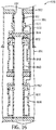
- Fig. 2 depicts a more detailed view of the lowermost section 80 in accordance with an exemplary implementation. It is noted that Fig. 2 , as well as other figures, schematically depict the lower completion assembly 20 as being generally symmetrically about a longitudinal axis 299, with the view on the lefthand side of the axis 299 being a perspective view and the view on the righthand side of the axis 299 being a cross-sectional view.
- the lowermost section 80 may be set inside a casing string 250 of the well 10.
- the sump packer 140 and an isolation packer 130 are set to form corresponding annular seals between the interior surface of the casing string 250 and the lower completion assembly 20; and as depicted in Fig. 2 , for this example, the casing string 250 and surrounding formation have been perforated prior to the running of the lower completion assembly 20 into the wellbore 12 to form corresponding perforation tunnels 254 in the general location of the screen 100.
- the return valve 104 and the flow control valve 110 control inflow fluid communication between the surrounding annulus outside of the lower completion assembly 20 and an inner tubing string 300 of the assembly 20. More specifically, inflow fluid is communicated through the screen 100 and depending on the open/closed states of the valves 104 and 110, is communicated through the valve 104 and/or valve 110 into a central passageway 320 of the lower completion assembly 20.
- a slurry flow is introduced, which flows into an annular region 302 surrounding the screen 100. Fluid from the slurry flow exits through the screen 100 and into an annular region 304 between the screen 100 and the exterior of the tubing string 300, leaving the gravel substrate surrounding the screen 100.
- Access to the central passageway 320 of the tubing 300 and thus, access to the central passageway of the lower completion assembly 20 is controlled during the gravel packing phase by the return valve 104.
- Closure of the return valve 104 (such as when the lower completion assembly 20 is run into the well 10 and possibly after gravel packing of the zone is complete) may be accomplished using, for example, a shifting tool that is run inside the lower completion assembly 20.
- the return valve 104 may be a sleeve valve that has an inner profile that is engaged by a corresponding outer profile (an outer surface of a collet, for example) of a service tool (not shown) that is run inside the central passageway 302.
- the upper completion assembly (not shown in Fig. 2 ) completes the control line communication path(s) to the Earth surface in accordance with exemplary implementations to allow remote control of the flow control valves 110 of the lower completion assembly 20.
- the flow control valves 110 selectively permit fluid communication between the annular regions 304 of each zone and the central passageway of the lower completion assembly 20.
- the flow control valve 110 is part of a ported flow control valve sub, or assembly 303, which includes the housing 108 and the flow control valve 110.
- the housing 108 forms connections with the inner tubing string 300; one or more control lines; and an outer section that contains the screen 100.
- the housing 108 includes an upper cap, or housing section 351, that has one or more control line feedthroughs.
- the control line(s) 200 include a first segment 200a extending uphole from the upper housing section 351; a second segment 200b extending from the segment 200a through one or more openings of the housing section 351 to the flow control valve 110 that is disposed inside the housing 108; and another segment 200c outside of the housing 108, which extends at one or more T junctions between the segments 200a and 200b and extends downwardly in a segment 200d outside of the housing 108.
- the lower completion assembly 20 may further include protection devices (not shown) for purposes of protecting the control line(s) segments where the control line(s) extend on the outside of the lower completion assembly 20, such as, for example, the segment 200d.
- the housing 108 further includes a radially expand intermediate housing section 352 and a lower cap, or housing section 360.
- the flow control valve 110 may have a variety of different designs, depending on the particular implementation.
- Fig. 4 depicts a flow control valve 400 in accordance with some implementations.
- the flow control valve 400 is an electrically-controlled valve that has an electric actuator 410 that is controlled by electrical signals that are communicated downhole via an electrical cable 401 (i.e., the "control line" for this example).
- the electric cable 401 passes through the isolation packer 130.
- the electrical cable 401 may contain multiple wires for purposes of communicating power and telemetry signals downhole. One or more of the wires of the electrical cable 401 may be used for purposes of communicating telemetry signals uphole.
- the electrical cable 401 may be coupled (via a wet connect inductive coupler, for example) to control line communication paths of an upper completion assembly.
- the communication paths of the upper completion assembly may include acoustic paths, wired paths, wireless paths, optical paths, wired pipe paths, electromagnetic communication paths, and so forth, which are coupled to corresponding control line communication paths of the lower completion assembly 20.
- signals that are communicated over the electrical cable 401 are received by a power and telemetry module 408 of the flow control valve 400.
- command-encoded electrical signals may be communicated downhole to the flow control valve 400 via the cable 401 for purposes of selectively actuating the valve 400.
- This actuation may include, as non-limiting example, fully opening or fully closing the electric flow control valve 400; setting the flow control valve 400 to a particular choke position, closing flow through the electric flow control valve 400; and so forth.
- the electrical actuator 410 controls longitudinal translation of a plunger 414, which, in turn, regulates flow between a longitudinally extending intake passageway 405 and a radial port 404, which are disposed in the tubing string 300.
- the tubing string 300 includes a section 300a, which includes the passageway 405 and the radial port 404 that establishes communication with the central passageway 303, depending on the position of the plunger 414.
- a tapered lower end of the plunger 414 is configured to mate with a complementary tapered seat 415 that is formed in an upper end of the longitudinal passageway 405 such that when the plunger 414 is fully disposed in the seat 415 (as shown in Fig. 4 ), fluid communication through the electric flow control valve 400 is closed.
- the electric actuator 410 longitudinally translates the plunger 414 in an upward direction to remove the lower end of the plunger 414 from the seat 415, fluid communication is established between the radial port 404 and the longitudinal passageway 405.
- longitudinal positions of the plunger 414 may be controlled for purposes of establishing different choke flow positions to selectively establish different cross-sectional flow areas for communicating flow between the annular region and the central passageway 302.
- the flow control valve 400 may include at least one sensor for purposes of acquiring information pertaining to sensed downhole conditions. This information, in turn, may be communicated uphole via the power and telemetry module 408 using one or more wires of the electrical cable 401 (as a non-limiting example).
- the flow control valve 400 may include one or more of the following sensors: a pressure sensor, a temperature sensor, a viscosity sensor, and so forth.
- an operator at the Earth surface of the well 10 may determine various parameters and control production for a given zone.
- a given sensor 420 may be disposed to sense a property of the fluid in the longitudinal passageway 405; and the electric flow control valve 400 may include a venturi sensor 428 that is disposed about the longitudinal passageway 405 for purposes of acquiring flow velocity measurements.
- Other and/or different sensors may be employed, in accordance with other implementations.
- sensors may be disposed on other parts or in other sections of the lower completion assembly 20.
- a plurality of flow control devices such as the electric flow control valves 400 may be peripherally distributed around at least part of the axis of the tubing section 300a.
- the electric flow control valves 400 are eccentrically disposed (as indicated by offset axes 450 and 454) around a given arcuate segment of the longitudinal axis of the section 300a in a "gatling gun" arrangement.
- the electric flow control valves 400 may be, for example, selectively fully opened and/or fully closed to establish a desired collective choke position, or cross-sectional flow area, for regulating flow into a given zone.
- the flow control valves 400 for this implementation may be cartridge valves.
- the flow control valves 400 may be controlled to have selectable variable cross-sectional flow areas.
- a technique 600 may be used in connection with the lower completion assembly 200 for purposes of completing a well and transitioning the well to a production phase.
- the zones of the well 10 are first perforated (block 604) and then, a fluid loss pill may be communicated into the well 10, pursuant to block 608.
- the lower completion assembly 20 is then run into the well 10 with the flow control valves 110, the return valves 104 and the port control valves 150 closed; and the packers of the lower completion assembly 20 are then set, pursuant to block 612. In this manner, the lower completion assembly 20 may be run into the well 10 on a tubular string, in accordance with some implementations.
- a service string is run into the lower completion assembly, pursuant to block 616.
- the service string may also be the string that is used to run the lower completion assembly 20 into the well 10 and may be released from the lower completion assembly 20 to allow the service tool(s) of the service tool assembly 20 to perform downhole operations, manipulate valves of the assembly 20, and so forth.
- each service tool of the service tool string may include one or more collets that have predefined profiles for purposes of engaging the return valves 104 and port control valves 150 to selectively control the opening and closing of these valves, in accordance with some implementations.
- the service string may further include a tubular string that extends uphole to the Earth surface of the well for purposes of communicating fluids and/or gravel-laden slurry downhole for purposes of using the lower completion assembly 20 to perform such operations as a gravel packing operation, a fracturing operation, a combined gravel packing and fracturing operation, a stimulation operation, an acidizing operation, and so forth.
- the technique 600 next includes performing the gravel packing phase in which the zones are gravel packed (or concurrently fractured and gravel packed, depending on the implementation), beginning with the lowermost zone and proceeding uphole in a sequential fashion.
- the service tool string is positioned (block 620) in the next zone to be gravel packed/fractured and used to open the return valve 104 and port control valve 150 associated with the zone.
- the gravel packing operation is performed (block 624) in the zone.
- the gravel slurry is communicated through the service string and via the appropriate port control valve 150 into the annular region that surrounds the screen 100 such that excess fluid is communicated through the screen 100 and returns to the Earth surface.
- the gravel packing operation may be associated with a fracturing operation in which an increased fluid pressure is used for purposes of fracturing the zone.
- control returns to block 620 in which the service tool is repositioned and manipulated accordingly to open and close the appropriate valves and deliver the slurry flow.
- the service string is retrieved (block 632) from the well 10 and the upper completion assembly is then run (block 636) into the well to mate the control line(s) of the upper completion assembly with the control line(s) of the lower completion assembly.
- the control line(s) of the upper and lower completion assemblies may then be used to selectively control fluid communication through the flow control passageways of the flow control valves 110 for the production phase, pursuant to block 640.
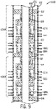
- Fig. 9 depicts a single trip, multiple zone lower completion assembly 650 that may be used in connection with gravel packing and fracturing operations, in accordance with some implementations.
- the lower completion assembly 650 is installed in a cased section of a wellbore, which is cased by a corresponding casing string 652; and the lower completion assembly 650 extends into two exemplary cased zones 654 and 656. It is noted that the lower completion assembly 650 may extend through more than two zones, depending on the particular implementation.
- an upper zone 654 is formed between isolation packers 662 and 690 of the lower completion assembly 650; and a lower zone 656 is formed between the isolation packer 690 and a lower isolation packer 694.
- the components of the lower completion assembly 650, such as the packers 662, 690 and 694 are generally disposed on an inner tubing string 660 of the assembly 650.
- the lower completion assembly 650 includes multiple flow control valves 668 for each zone; and these multiple flow control valves are longitudinally distributed along the zone.
- the lower completion assembly 650 in the upper zone 654, includes an upper flow control valve 668 and a lower flow control valve 682 that is disposed below the upper flow control valve 668.
- the upper flow control valve 668 may be operated after the installation of an upper completion assembly (not shown in Fig. 9 ) for purposes of regulating flow through a screen 674 of the lower completion assembly 650 and an inner, central passageway of the tubing string 660, as described above.
- the lower fluid control valve 682 in the zone 654 may be operated when the upper completion assembly is installed for purposes of regulating communication of a flow through a corresponding screen 684 into the central passageway of the tubing string 660.
- the tubing string 660 of the lower completion assembly 650 further includes a port control valve 664 (a sleeve valve, for example) for the upper zone 654, which may be operated by a shifting tool (not shown in Fig. 9 ) of a service string for purposes of performing a gravel packing operation, a fracturing operation, a stimulation operation, an acidizing operation, and so forth for the zone 654.
- tubing string 660 may further include return valves (sleeve valves, for example) 680 and 686, which are disposed to regulate flow through the screens 674 and 684, respectively, during gravel packing operations for purposes of receiving slurry fluid into the central passageway of the tubing string 660.
- return valves sleeves valves, for example
- the lower completion assembly 650 may include at least one control line 670 (an electrical cable, a hydraulic control line, and so forth), which extends to the flow control valve 668 and 682, as described above, for purposes of controlling the flow control valves 668 and 682 during the production phase of the well.
- control line 670 an electrical cable, a hydraulic control line, and so forth
- the lower completion assembly 650 has a similar design and employs similar components (denoted by similar reference numerals) for the lower zone 656, in accordance with example implementations.
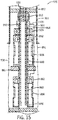
- the port control valves 664 may be selectively opened and closed for purposes of communicating a flow between the central passageway of the tubing string 660 and an annular region in the appropriate zone 654, 656. After these operations are complete and the port control valves 664 are closed, it may be particularly challenging to maintain seals through the closed port control valves 664. Therefore, referring to Fig. 10 , in accordance with some implementations, an isolation straddle seal assembly 700 may be run inside the lower completion assembly 650 to provide more effective fluid seals for the closed port control valves 664, as well as allow additional, backup control of the lower completion assembly 650 during the production phase. In general, Fig. 10 depicts the lower completion assembly 650 after the isolation straddle seal assembly 700 has been run into and installed inside the inner tubing string 660 of the lower completion assembly 650.
- the isolation straddle seal assembly 700 includes sections, such as exemplary sections 704 and 706, which form corresponding seals to seal off the port control valves 664 from the central passageway of the tubing string 660.
- each section 704, 706 may contain a sleeve with corresponding seals (o-rings, for example), which straddle the port control valves 664 for purposes of sealing off (and thereby preventing any possible leakage through) the closed valves 664.
- the isolation straddle seal assembly 700 also includes, in accordance with exemplary implementations, radial ports 710, 712, 714 and 716 (depicted as examples), which align with the corresponding outlets of the flow control valves 668 to thereby permit fluid communication through the flow control valves 664 and the central passageway of the tubing string 660, as selectively controlled by the states of the flow control valve 664.
- the isolation straddle seal assembly 700 may further include valves 720, 724, 726 and 728 (depicted as non-limiting examples), such as sleeve valves, which provides backup control in case one or more of the flow control valves 664 stop properly functioning (fail closed, for example).
- valves 720, 724, 726 and 728 are generally aligned with corresponding return valves 686 of the lower completion assembly 650.
- the bottom end of the isolation straddle seal assembly 700 includes a return valve shifting tool 730 that is constructed to shift the return sleeves 680 open as the assembly 700 is run into the lower completion assembly 650.
- the shifting tool 730 may have a collet with an outer profile that corresponds to an inner profile of the return valves 664 for purposes of engaging the return valves 664 in a sequential manner to open the return valves 664 as the isolation straddle seal assembly 700 is run into the lower completion assembly 650.
- the isolation straddle seal assembly 700 has been fully run into the lower completion assembly 650, as depicted in Fig. 10 , all of the return valves 664 are open, but fluid communication into the central passageway of the tubing string 660 is controlled by the valves 720, 724, 726 and 728.
- valves 720, 724, 726 and 728 are closed, if the corresponding flow control valves 668 operate properly. However, if a particular flow control valve 668 should fail and not be able to be opened or adjusted to the proper setting, the corresponding valve 720, 724, 726 or 728 may be opened (shifted open by a corresponding shifting tool, for example) to establish communication in an alternative path.
- a lower completion assembly 750 may be used in place of the lower completion assembly 650 (see Fig. 9 , for example).
- the lower completion assembly 750 has multiple flow control valves 668 per zone, with the flow control valves 668 being arranged around the periphery of an inner tubing string 752 of the lower completion assembly 750, similar to the arrangement depicted in, for example, Fig. 5 .
- the lower completion assembly 750 has a single screen assembly 754 (a screen and shroud, for example) per zone or multiple screen joints connected with flow passage between joint directing flow from all screen joints to flow control valve 668.
- the lower completion assembly 750 has a single return valve 756 per zone.
- an isolation straddle seal assembly 760 may be run into the lower completion assembly 750 after fracturing and gravel packing and/or other operations are complete to prepare the lower completion assembly 750 for production. Similar to the isolation straddle seal assembly 700 (see Fig. 10 , for example), the isolation straddle seal assembly 760 includes sections 762 and 768, which seal off the port control valves 664 of the upper 654 and lower 656 zones, respectively.
- an inner tubing string 761 of the isolation straddle seal assembly 760 has ports 764 and 770, which are aligned with the flow control valve 664.
- the isolation straddle seal assembly 760 includes valves 766 and 770 (sliding sleeve valves, for example), which are used as backup valves to selectively provide alternative paths for the return valves 756 of the upper 654 and lower 656 zones, respectively.
- the isolation straddle seal assembly 760 includes a return valve shifting tool 780 at the lower end of the tubing string 761 for purposes of opening the port control valve 664 when the assembly 750 is run into the lower completion assembly 760.
- an upper completion assembly 800 may be subsequently run into the well to mate with the lower completion assembly 750 to enable the flow control valves 668 to be controlled from the Earth surface as well as otherwise configure the lower completion assembly 750 to be used during the production phase.
- the upper completion assembly 800 includes a production tubing string 810, which extends upwardly to communicate produced well fluid to the Earth surface. Because the production tubing string hanger and lower completion assembly 750 present corresponding fixed connection points, the upper completion assembly 800 includes a contraction joint 814 to provide a degree of movement and flexibility for mating the upper completion assembly 800 with the lower completion assembly 750.
- the upper completion assembly 800 includes a lower tubular section 815 that is mounted to the upper side of the contraction joint 814; and the upper end of the lower completion assembly 750 is attached to the lower end of the contraction joint 814.
- the upper completion assembly 800 includes an inductive coupler 816, which is constructed to inductively couple wires of an electric cable 811 that is in communication with the Earth surface to the corresponding wires of the electrical cable 670.
- the upper completion assembly 800 may not include the inductive coupler 816.
- the inductive coupler 816 inductively couples the electrical signals to a corresponding inductive coupler 790 located at the upper end of the lower completion assembly 750, as depicted in Fig. 13 .
- an electrical wet connect in place of inductive coupler may be used.
- the lower end of the upper completion assembly 800 includes a hydraulic wet connect coupler 820 that is disposed below the inductive coupler 816 (if used) to connect one or more hydraulic lines that extend to the Earth surface to one or more hydraulic lines that extend downhole to components of the lower completion assembly 750.
- these components may include one or more flow control valves 668.
- the hydraulic wet connect coupler 820 forms a connection with a corresponding hydraulic wet connect coupler 792 of the lower completion assembly 750, which is disposed at the upper end of the lower completion assembly 750.
- a lower completion assembly 850 which employs use of standalone screen assemblies, may be run downhole to extend inside an uncased wellbore segment 851.
- the lower completion assembly 850 may include an inner tubing string 856, which includes packers 870, 872 and 874 for purposes of establishing multiple zones into which the standalone screen assemblies extend.
- the upper packer 870 is set inside the casing string 852, with the remainder of the lower completion assembly 850 extending into the uncased wellbore segment 851.
- the inner tubing string 856 may include an inductive coupler assembly 858 for purposes of communicating signals from an electrical cable 854 to downhole components of the lower completion assembly 850, such as flow control valves 862.
- each zone may include multiple flow control valves 862, which, in accordance with some implementations, are arranged around the periphery, as depicted in Fig. 5 .
- the inner tubing string 856 may contain an arrangement of peripherally-disposed flow control valves 862, which may be selectively operated to control flow of fluid that flows through an associated screen assembly into the central passageway of the tubing string 856.
- the screen assembly may include an outer shroud 858 and an inner screen 860.
- the tubing string 856 may further include a return valve 864 (a sleeve valve, for example), which provides an alternative path to regulate flow communication (via a shifting tool, for example), should the flow control valves 862 of the zone fail or not operate properly.
- a return valve 864 a sleeve valve, for example
- the packers 872 and 874 may be open hole isolation packers, such as swellable packers, hydraulically-set packers, mechanically-set packers and so forth.
- electric power may be used to activate swelling of the packers 872 and 874.
- a lower completion assembly 900 may be used as part of an open hole gravel packing assembly.
- the lower completion assembly 900 includes an inner tubing string 954, which includes a gravel pack packer 852 that forms an annular seal inside a casing string 852.
- the lower completion assembly 900 extends from the lower end of the casing section 852 into an uncased wellbore segment 906.
- the lower completion assembly 900 includes multiple screen assemblies (two screen assemblies being depicted in Fig. 15 ), which each includes an outer shroud 858 and an inner screen 860. As shown in Fig.
- the two depicted screen assemblies are separated by an open hole isolation packer 861, such as a swellable packer, a hydraulically-set packer, a mechanically-set packer, and so forth. Gravel packing shunt paths may extend through the packer 861.
- the lower completion assembly 900 further includes a port control valve 910, which is part of the inner tubing string 901 and is disposed above the screen assemblies.
- the lower completion assembly 900 is used to pack gravel around all of the screens in one operation.
- the open hole isolation packer 861 remains unset, so that gravel pack slurry that is communicated inside an inner washpipe 950 via a gravel pack service tool 954 may be communicated through the port control valve 910 and into the annular region between the borehole segment wall 851 and the screen assemblies.
- Slurry fluid from the gravel packing operation returns through the sleeves and corresponding flow control valves 862 into the central passageway of the washpipe 950.
- the lower completion assembly 900 includes a formation isolation valve 924, which is part of the tubing string 901 and in the particular example implementation that is depicted in Fig. 15 is disposed above the flow control valves 862.
- the formation isolation valve 924 is open, which permits entry of a washpipe 861 during the gravel packing operation as well as communication of the returning slurry fluid to the gravel pack service tool 954.
- the washpipe 950 and gravel pack service 954 are withdrawn; and the formation isolation valve 924 is closed, thereby isolating the region below the formation isolation valve 924.
- the formation isolation valve 924 may be a mechanically-control valve (controlled via a shifting tool, for example), in accordance with some implementations.
- the washpipe 950 may include a formation isolation valve shifting tool 956 at its lower end for purposes of controlling the open and closed states of the formation isolation valve 924.
- the formation isolation valve shifting tool 956 may contain a collet that has a profile that corresponds to an inner profile of the formation isolation valve 924 so that manipulation of the washpipe 950 may be employed for purposes of selectively opening and closing the formation isolation valve 924.
- an isolation straddle seal assembly 960 may be run downhole inside the lower completion assembly 900 to prepare the assembly 900 for the production phase. Similar to the isolation seal assemblies disclosed above, the isolation seal assembly 960 includes ports 961 and 964, which align with corresponding outlets of the flow control valves 862. The isolation straddle seal assembly 960 further includes valves 962 and 966 (sliding sleeve valves, for example), which may be operated for purposes of selectively establishing alternative paths through the screen assemblies should the flow control valves 862 not function properly. In this manner, the valves 962 and 966 may be operated by a shifting tool on a string that is run inside the isolation straddle seal assembly 960, in accordance with some implementations.
- Fig. 18 depicts the installation of an upper completion assembly 980 and the mating of the assembly 980 with the lower completion assembly 900.
- the upper completion assembly 980 includes an isolation seal section 986, which isolates the port control valve 985.
- the lower end of the upper completion 980 may include an inductive coupler 984 for purposes of inductively coupling wire of an electric cable 991 to corresponding wires of the lower completion assembly 900 (wires extending to the flow control valves 862, for example).
- the lower end of the upper completion assembly 980 may include a wet connect hydraulic coupler as well as may include both hydraulic wet connect couplers and inductive couplers.
Description
- For purposes of forming a well to extract a hydrocarbon-based fluid (oil or natural gas) from a hydrocarbon-bearing geological formation, a wellbore is first drilled into the formation and completion equipment, which typically includes a complex system of tubes and valves, is installed in the wellbore to regulate the production of well fluid from the well. Reference is for example made to
US 2009/025923 A1 in the name of the same applicant. - The completion equipment may include sand control equipment, such as screens and filtering media, and a production tubing string to communicate well fluid to the Earth surface. Installing the completion equipment, as well as conducting downhole operations associated with completing the well, such as gravel packing and/or fracturing operations, may involve multiple runs, or trips, into the well. In general, each trip into the well may add to the cost and complexity associated with completing the well.
- In a first aspect, the present invention resides in a method as defined in
claim 1. Preferred embodiments are defined in claims 2 to 5. - In another aspect, the present invention resides in a system as defined in claim 6. Preferred embodiments are defined in
claims 7 to 18. - Advantages and other features will become apparent from the following drawings, description and claims.
-
-
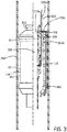
Fig. 1 is a schematic diagram of a well illustrating a single trip, multiple zone lower completion assembly according to an example implementation. -
Fig. 2 is a schematic diagram illustrating a lowermost section of the lower completion assembly ofFig. 1 according to an example implementation. -
Fig. 3 is a schematic diagram of a flow control valve assembly ofFig. 2 according to an example implementation. -
Fig. 4 is a schematic diagram illustrating operation of a flow control valve of the flow control valve assembly ofFig. 3 according to an example implementation. -
Fig. 5 is a cross-sectional view taken along 5-5 ofFig. 4 according to an example implementation. -
Fig. 6 is a schematic diagram illustrating coupling of the lower completion assembly to an upper completion assembly according to an example implementation. -
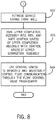
Figs. 7 and8 illustrate a flow diagram of a technique to install and use a lower completion assembly and an upper completion assembly according to an example implementation. -
Fig. 9 is a schematic diagram of a single trip, multiple zone lower completion assembly that may be used in downhole fracturing and/or gravel packing operations according to an example implementation. -
Fig. 10 is a schematic diagram of the lower completion assembly ofFig. 9 after an isolation straddle seal assembly is run into the lower completion assembly according to an example implementation. -
Fig. 11 is a schematic diagram of a single trip, multiple zone lower completion assembly that may be used in fracturing and/or gravel packing operations according to a further example implementation. -
Fig. 12 is a schematic diagram of the lower completion assembly ofFig. 11 after an isolation straddle seal assembly is run into the lower completion assembly according to an example implementation. -
Fig. 13 is a schematic diagram of upper and lower completion assemblies according to an example implementation. -
Fig. 14 is a schematic diagram of a single trip, multiple zone lower completion assembly that has a standalone screen assembly according to an example implementation. -
Fig. 15 is a schematic diagram of a single trip, multiple zone lower completion assembly that may be used in gravel packed open hole completion according to an example implementation. -
Fig. 16 is a schematic diagram illustrating the lower completion assembly ofFig. 15 after the use and subsequent retrieval of a service tool string according to an example implementation. -
Fig. 17 is a schematic diagram of the lower completion assembly ofFig. 15 after a straddle seal isolation assembly is run into the lower completion assembly according to an example implementation. -
Fig. 18 is an illustration of an upper completion assembly and the lower completion assembly ofFig. 15 according to an example implementation. - In the following description, numerous details are set forth to provide an understanding of embodiments of the present invention. However, it will be understood by those skilled in the art that the present invention may be practiced without these details and that numerous variations or modifications from the described embodiments may be possible.
- In the specification and appended claims: the terms "connect", "connection", "connected", "in connection with", and "connecting" are used to mean "in direct connection with" or "in connection with via another element"; and the term "set" is used to mean "one element" or "more than one element". As used herein, the terms "up" and "down", "upper" and "lower", "upwardly" and downwardly", "upstream" and "downstream"; "above" and "below"; and other like terms indicating relative positions above or below a given point or element are used in this description to more clearly describe some embodiments of the invention. Moreover, the term "sealing mechanism" includes: packers, bridge plugs, downhole valves, sliding sleeves, baffle-plug combinations, polished bore receptacle (PBR) seals, and all other methods and devices for blocking the flow of fluids through the wellbore.
- Running an intelligent completion that includes flow control valves inside a screen in a well that are completed using sand control operations (e.g., gravel packing or frac packing operations) may not be commercially attractive, as it may be challenging to run relatively large flow control valves inside a relatively small internal diameter screen. Because of this reason, flow control valves may be run on a separate trip and placed above the screen. However, this arrangement may limit the number of zones (two zones, for example) that may be controlled from a given flow control valve. Completion systems and techniques are disclosed herein to independently control flow from wells having many zones (more than two zones, for example). More specifically, the completion systems that are disclosed herein integrate the flow control valve with the screen and gravel packing operations, which allows independent control of flow from more than two zones in a well, which uses sand control.
- Referring to
Fig. 1 , a well 10 includes at least onewellbore 12, which extends through one or more hydrocarbon-bearing formations that contain a hydrocarbon-based fluid, such as oil or gas. Thewellbore 12 may be cased by a casing string, may be uncased or may contain cased and uncased segments, depending on the particular implementation. Moreover, although thewellbore 12 is depicted as being a vertical wellbore segment, thewellbore 12 may be a lateral wellbore or may contain a lateral wellbore segment, in accordance with other implementations. In general, the well 10 may be a subterranean terrestrial well or may be a subsea well, depending on the particular implementation. - For the example that is depicted in
Fig. 1 , alower completion assembly 20 has been installed in a single run, or trip, into thewellbore 12. In this manner, as a non-limiting example, a tubular work string (not shown) may be employed for purposes of running thelower completion assembly 20 downhole from the Earth surface into position and setting one or more packers of thelower completion assembly 20 to secure theassembly 20 in position, as depicted inFig. 1 . - The
lower completion assembly 20, in accordance with implementations disclosed herein, includes at least one flow control valve 110 (a cartridge valve, a solenoid-operated valve and/or a control line-operated valve, an electric valve, a hydraulic valve or electro-hydraulic valve as non-limiting examples); one or more circulating, or port control valves 150 (a sleeve valve, as a non-limiting example); one or more return valves 104 (a sleeve valve, as a non-limiting example); and one or more sand production control devices, such asscreens 100. As non-limiting examples, thescreen 100 may be a wire-wrapped screen, a mesh screen or a sand production control assembly that includes a combination of different filtering media, depending on the particular implementation. Moreover, thescreen 100 may be disposed inside a protective shroud (not shown). - In accordance with exemplary implementations, the
lower completion assembly 20 may be longitudinally partitioned into sections (exemplary uppermost 30, intermediate 60 and lower 80 sections, being depicted inFig. 1 ), which correspond to different segments, or zones, along thewellbore 12. Each section of thelower completion assembly 20 contains components to aid operations involved in completing the associated zone (fracturing, and gravel packing operations, for example) as well as components to regulate the subsequent production of well fluid from the zone. - For example, the
uppermost section 30 of thelower completion assembly 20 may include such features as aflow control valve 110, areturn valve 104, ascreen 100 and aport control valve 150. Theuppermost section 30 corresponds to a particular segment, or zone, of thewellbore 12 and extends between an uppergravel packing packer 120 of thelower completion assembly 20 and alower isolation packer 130, which defines the upper boundary of the next zone and the lower boundary of the zone associated with thesection 30. Depending on the particular implementation, thepackers 120 and/or 130 may be weight-set packers, mechanically-set packers, inflatable packers, swellable packers, hydraulically-set packers, etc. Thescreen 100 may longitudinally extend along thewellbore 12 for a distance of several feet to several hundred feet (300 feet, as a non-limiting example), depending on the particular implementation. - In general, the
return valve 104 is disposed closer to the lower end of thescreen 100 than to the upper end of thescreen 100, and as depicted inFig. 1 , may be circumscribed by thescreen 100. Thereturn valve 104 may be selectively operated, as further disclosed herein, during a gravel packing and/or fracturing operation for purposes of allowing the return of fluid into the central passageway of thelower completion assembly 20. - More specifically, in accordance with some implementations, all of the return valves 104 (i.e., the
return valve 104 of theuppermost completion section 30 and thereturn valves 104 of theother sections 60 and 80) of thelower completion assembly 20 are initially closed when theassembly 20 is run into thewell 10; and thereturn valves 104 are opened one at a time as the zones are sequentially gravel packed/fractured in an uphole direction. Thus, when it is time to gravel pack and/or fracture the zone associated with theuppermost section 30, for example, thereturn valve 104 of theuppermost section 30 is opened (via a shifting tool on a service string that is run inside thelower completion assembly 20, for example) to open communication between the central passageway of thesection 30 and the surrounding annulus. - Moreover, to gravel pack and/or fracture the zone that is associated with the
uppermost section 30, theport control valve 150 of thesection 30 is opened (via a shifting tool on a service string, for example) so that a gravel slurry may be communicated from the central passageway of thelower completion assembly 20, through one or more radial ports of theport control valve 150 and into the annulus surrounding thescreen 100. In the gravel packing operation, fluid from the slurry exits the slurry, thereby leaving a gravel substrate surrounding thescreen 100. This fluid, in turn, returns to the central passageway of theuppermost section 30 through theopen return valve 104. It is noted that a service tool string inside thelower completion assembly 20 may include at least one crossover tool for purposes of juxtapositioning flows of the slurry and slurry fluid between the central passageway and annulus of thelower completion assembly 20, as can be appreciated by the skilled artisan. - In accordance with some implementations, the gravel packing operation may be combined with a fracturing operation (in a "frac-pack operation"). Moreover, although gravel packing and fracturing are mentioned herein as examples of downhole operations that may be aided by the components of the
lower completion assembly 20, other operations, which may include stimulation operations, acidizing operations, and so forth, may be performed using thelower completion assembly 20, in accordance with other implementations. - Unlike the
return valve 104, theflow control valve 110 of theuppermost section 30 is used for purposes of controlling production from the zone that is associated with thesection 30. Thus, in general, theflow control valve 110 is not used or controlled during the gravel packing phase and is run into the well 10 initially closed. More specifically, in accordance with exemplary implementations, theflow control valve 110 is constructed to be primarily controlled by one ormore control lines 200 to regulate production from the associated zone during the production phase of the well 10. In this manner, one or more control stimuli may be communicated downhole from the Earth surface of the well 10 via the control line(s) 200 during the production phase for purposes of controlling the cross-sectional flow area through theflow control valve 110. As non-limiting example, the stimuli used to control theflow control valve 110 may include hydraulic pressure, hydraulic pressure pulses, electrical stimuli, optical stimuli, acoustic stimuli and so forth; and thecontrol valve 110 has the appropriate telemetry interfaces and actuators to respond to the particular stimuli that are used. During the gravel packing phase, however, a control line communication path does not exist between thelower completion assembly 20 and the Earth surface of the well. As further described below, the control line communication path(s) are completed by one or more control lines of an upper completion assembly, which extends to the Earth surface. Thus, during the gravel packing phase (i.e., before the upper completion assembly is installed), control line operation of theflow control valve 110 is disabled. - Depending on the particular implementation, the
flow control valve 110 may have a single open position (associated with a fixed cross-sectional flow area) to permit fluid communication between the central passageway of thesection 30 and the annulus; or alternatively, in accordance with other implementations, theflow control valve 110 may have multiple choke positions in which different cross-sectional flow paths may be selected (via the appropriate control line stimuli) between the central passageway and the annulus. Thus, in the former implementation, theflow control valve 110 may be used to permit or isolate a particular zone of the well 10; and in the latter implementation, theflow control valve 110 may be controlled for purposes of isolating flow from the zone if closed or if open, regulating a particular cross-sectional flow area from the associated zone. Moreover, as further described below, in accordance with example implementations, each section of thelower completion assembly 20, such as thesection 30, may contain multipleflow control valves 110 that are selectively controlled (some are opened and some are closed, for example) for purposes of regulating the inflow from the associated zone. - As depicted in
Fig. 1 , in accordance with some implementations, theflow control valve 110 of theuppermost section 30 may be disposed in a radially expandedhousing 108 of theuppermost section 30. Due to this design, theflow control valve 110 is capable of regulating a relatively large inflow (as compared to the inner diameter in the non-flow control valve housing sections of the lower completion assembly 20) into the central passageway of thelower completion assembly 20. As further described below, in accordance with some implementations, thehousing 108 is part of a sub with three ports, which forms one or more sealed connections for one ormore control lines 200 that are inside thehousing 108 for purposes of connecting thecontrol lines 200 to theflow control valve 110. Thus, thecontrol lines 200, in general, extend along the exterior of thesection 30, as well as extend into thehousing 108 for purposes of connecting to theflow control valve 110 inside thehousing 108. - In accordance with an exemplary implementation, a
wet connect coupler 180 is disposed at the upper end of thelower completion assembly 20 for purposes of coupling the control line(s) 200 to one or more corresponding control lines of the subsequently installed upper completion assembly (not shown inFig. 1 ). In this manner, referring toFig. 6 in conjunction withFig. 1 , in accordance with an exemplary implementation, alower portion 500 of an upper completion assembly may include one ormore control lines 504 that, via an associatedwet connect coupler 508 that is disposed at the lowermost end of the upper completion assembly, couples to the control line(s) 200. The control line(s) 504, in turn, extend (on the outside of a production tubing string, for example) to the Earth surface or near the Earth surface for purposes of allowing a surface operator to, after installation of the upper completion assembly, remotely control theflow control valve 110. As described below, in accordance with exemplary implementations, thewet connect couplers - Referring back to
Fig. 1 , in addition to theuppermost section 30, thelower completion assembly 20 includes one or moreintermediate sections 60 that extend in one or more associated zones, in accordance with exemplary implementations. In general, eachintermediate section 60 extends between anisolation packer 130, which is disposed at the upper end of thesection 60 and acorresponding isolation packer 130 that is disposed at the lower end ofsection 60. Moreover, similar to theuppermost section 30, a givenintermediate section 60 may include aport control valve 150, aflow control valve 110, ascreen 100 and areturn valve 104, which are run downhole as a unit with thelower completion assembly 20 and, in general, are arranged and operate similarly to the corresponding components of theuppermost section 30. - In accordance with exemplary implementations, at its lower end, the
lower completion assembly 20 includes alowermost completion section 80 that extends between a given isolation packer (not shown) and asump packer 140 that is disposed at the lower end of thelower completion assembly 20. In general, thelower section 80 contains components similar to thesections port control valve 150, one or moreflow control valves 110, ascreen 100 and areturn valve 104. Moreover, these elements may be disposed relatively to each other and operate similarly to the components of thesections -
Fig. 2 depicts a more detailed view of thelowermost section 80 in accordance with an exemplary implementation. It is noted thatFig. 2 , as well as other figures, schematically depict thelower completion assembly 20 as being generally symmetrically about alongitudinal axis 299, with the view on the lefthand side of theaxis 299 being a perspective view and the view on the righthand side of theaxis 299 being a cross-sectional view. As shown for this non-limiting example, thelowermost section 80 may be set inside acasing string 250 of the well 10. For this example, thesump packer 140 and anisolation packer 130 are set to form corresponding annular seals between the interior surface of thecasing string 250 and thelower completion assembly 20; and as depicted inFig. 2 , for this example, thecasing string 250 and surrounding formation have been perforated prior to the running of thelower completion assembly 20 into thewellbore 12 to form corresponding perforation tunnels 254 in the general location of thescreen 100. - In general, in accordance with exemplary implementations, the
return valve 104 and theflow control valve 110 control inflow fluid communication between the surrounding annulus outside of thelower completion assembly 20 and aninner tubing string 300 of theassembly 20. More specifically, inflow fluid is communicated through thescreen 100 and depending on the open/closed states of thevalves valve 104 and/orvalve 110 into acentral passageway 320 of thelower completion assembly 20. During the gravel packing of the associated zone, a slurry flow is introduced, which flows into anannular region 302 surrounding thescreen 100. Fluid from the slurry flow exits through thescreen 100 and into anannular region 304 between thescreen 100 and the exterior of thetubing string 300, leaving the gravel substrate surrounding thescreen 100. Access to thecentral passageway 320 of thetubing 300 and thus, access to the central passageway of thelower completion assembly 20 is controlled during the gravel packing phase by thereturn valve 104. Thus, during the gravel packing/fracturing of the zone associated with thesection 80 when thereturn valve 104 is open, fluid flows from theannular region 304 into thecentral passageway 320 of thetubing 300. Closure of the return valve 104 (such as when thelower completion assembly 20 is run into the well 10 and possibly after gravel packing of the zone is complete) may be accomplished using, for example, a shifting tool that is run inside thelower completion assembly 20. As a non-limiting example, thereturn valve 104 may be a sleeve valve that has an inner profile that is engaged by a corresponding outer profile (an outer surface of a collet, for example) of a service tool (not shown) that is run inside thecentral passageway 302. - For the production phase, the upper completion assembly (not shown in
Fig. 2 ) completes the control line communication path(s) to the Earth surface in accordance with exemplary implementations to allow remote control of theflow control valves 110 of thelower completion assembly 20. Thus, during this phase, depending on the particular control settings for theflow control valves 110, theflow control valves 110 selectively permit fluid communication between theannular regions 304 of each zone and the central passageway of thelower completion assembly 20. - Referring to
Fig. 3 , in accordance with exemplary implementations, theflow control valve 110 is part of a ported flow control valve sub, orassembly 303, which includes thehousing 108 and theflow control valve 110. Thehousing 108 forms connections with theinner tubing string 300; one or more control lines; and an outer section that contains thescreen 100. Thehousing 108 includes an upper cap, orhousing section 351, that has one or more control line feedthroughs. In this regard, for the exemplary implementation that is depicted inFig. 5 , the control line(s) 200 include afirst segment 200a extending uphole from theupper housing section 351; asecond segment 200b extending from thesegment 200a through one or more openings of thehousing section 351 to theflow control valve 110 that is disposed inside thehousing 108; and anothersegment 200c outside of thehousing 108, which extends at one or more T junctions between thesegments segment 200d outside of thehousing 108. Thelower completion assembly 20 may further include protection devices (not shown) for purposes of protecting the control line(s) segments where the control line(s) extend on the outside of thelower completion assembly 20, such as, for example, thesegment 200d. Thehousing 108 further includes a radially expandintermediate housing section 352 and a lower cap, orhousing section 360. - The
flow control valve 110 may have a variety of different designs, depending on the particular implementation. As a non-limiting example,Fig. 4 depicts aflow control valve 400 in accordance with some implementations. For these implementations, theflow control valve 400 is an electrically-controlled valve that has anelectric actuator 410 that is controlled by electrical signals that are communicated downhole via an electrical cable 401 (i.e., the "control line" for this example). As shown inFig. 4 , theelectric cable 401 passes through theisolation packer 130. - As a non-limiting example, the
electrical cable 401 may contain multiple wires for purposes of communicating power and telemetry signals downhole. One or more of the wires of theelectrical cable 401 may be used for purposes of communicating telemetry signals uphole. In general, theelectrical cable 401 may be coupled (via a wet connect inductive coupler, for example) to control line communication paths of an upper completion assembly. In general, the communication paths of the upper completion assembly may include acoustic paths, wired paths, wireless paths, optical paths, wired pipe paths, electromagnetic communication paths, and so forth, which are coupled to corresponding control line communication paths of thelower completion assembly 20. - In general, signals that are communicated over the
electrical cable 401 are received by a power andtelemetry module 408 of theflow control valve 400. In this manner, in accordance with some implementations, command-encoded electrical signals may be communicated downhole to theflow control valve 400 via thecable 401 for purposes of selectively actuating thevalve 400. This actuation may include, as non-limiting example, fully opening or fully closing the electricflow control valve 400; setting theflow control valve 400 to a particular choke position, closing flow through the electricflow control valve 400; and so forth. - For the example that is depicted in
Fig. 4 , theelectrical actuator 410 controls longitudinal translation of aplunger 414, which, in turn, regulates flow between a longitudinally extendingintake passageway 405 and aradial port 404, which are disposed in thetubing string 300. In this manner, as shown inFig. 4 , in accordance with an exemplary implementation, thetubing string 300 includes asection 300a, which includes thepassageway 405 and theradial port 404 that establishes communication with thecentral passageway 303, depending on the position of theplunger 414. In this manner, in accordance with exemplary implementations, a tapered lower end of theplunger 414 is configured to mate with a complementarytapered seat 415 that is formed in an upper end of thelongitudinal passageway 405 such that when theplunger 414 is fully disposed in the seat 415 (as shown inFig. 4 ), fluid communication through the electricflow control valve 400 is closed. However, when theelectric actuator 410 longitudinally translates theplunger 414 in an upward direction to remove the lower end of theplunger 414 from theseat 415, fluid communication is established between theradial port 404 and thelongitudinal passageway 405. Likewise, longitudinal positions of theplunger 414 may be controlled for purposes of establishing different choke flow positions to selectively establish different cross-sectional flow areas for communicating flow between the annular region and thecentral passageway 302. - Among its other features, in accordance with an exemplary implementation, the
flow control valve 400 may include at least one sensor for purposes of acquiring information pertaining to sensed downhole conditions. This information, in turn, may be communicated uphole via the power andtelemetry module 408 using one or more wires of the electrical cable 401 (as a non-limiting example). As non-limiting examples, theflow control valve 400 may include one or more of the following sensors: a pressure sensor, a temperature sensor, a viscosity sensor, and so forth. - By monitoring the data acquired by the sensor(s), an operator at the Earth surface of the well 10 may determine various parameters and control production for a given zone. As a more specific non-limiting example, depicted in
Fig. 4 , a givensensor 420 may be disposed to sense a property of the fluid in thelongitudinal passageway 405; and the electricflow control valve 400 may include aventuri sensor 428 that is disposed about thelongitudinal passageway 405 for purposes of acquiring flow velocity measurements. Other and/or different sensors may be employed, in accordance with other implementations. Moreover, in accordance with some implementations, sensors may be disposed on other parts or in other sections of thelower completion assembly 20. - Referring to
Fig. 5 , in accordance with some implementations, a plurality of flow control devices, such as the electricflow control valves 400 may be peripherally distributed around at least part of the axis of thetubing section 300a. For this example, the electricflow control valves 400 are eccentrically disposed (as indicated by offsetaxes 450 and 454) around a given arcuate segment of the longitudinal axis of thesection 300a in a "gatling gun" arrangement. With this arrangement, the electricflow control valves 400 may be, for example, selectively fully opened and/or fully closed to establish a desired collective choke position, or cross-sectional flow area, for regulating flow into a given zone. As a non-limiting example, theflow control valves 400 for this implementation may be cartridge valves. In other implementations, theflow control valves 400 may be controlled to have selectable variable cross-sectional flow areas. - Referring to
Fig. 7 , in accordance with an exemplary implementation, atechnique 600 may be used in connection with thelower completion assembly 200 for purposes of completing a well and transitioning the well to a production phase. Pursuant to thetechnique 600, the zones of the well 10 are first perforated (block 604) and then, a fluid loss pill may be communicated into the well 10, pursuant to block 608. Thelower completion assembly 20 is then run into the well 10 with theflow control valves 110, thereturn valves 104 and theport control valves 150 closed; and the packers of thelower completion assembly 20 are then set, pursuant to block 612. In this manner, thelower completion assembly 20 may be run into the well 10 on a tubular string, in accordance with some implementations. - Next, according to the
technique 600, a service string is run into the lower completion assembly, pursuant to block 616. In further implementations, the service string may also be the string that is used to run thelower completion assembly 20 into the well 10 and may be released from thelower completion assembly 20 to allow the service tool(s) of theservice tool assembly 20 to perform downhole operations, manipulate valves of theassembly 20, and so forth. In general, each service tool of the service tool string may include one or more collets that have predefined profiles for purposes of engaging thereturn valves 104 andport control valves 150 to selectively control the opening and closing of these valves, in accordance with some implementations. The service string may further include a tubular string that extends uphole to the Earth surface of the well for purposes of communicating fluids and/or gravel-laden slurry downhole for purposes of using thelower completion assembly 20 to perform such operations as a gravel packing operation, a fracturing operation, a combined gravel packing and fracturing operation, a stimulation operation, an acidizing operation, and so forth. - As an example, the
technique 600 next includes performing the gravel packing phase in which the zones are gravel packed (or concurrently fractured and gravel packed, depending on the implementation), beginning with the lowermost zone and proceeding uphole in a sequential fashion. In this manner, the service tool string is positioned (block 620) in the next zone to be gravel packed/fractured and used to open thereturn valve 104 andport control valve 150 associated with the zone. Next, the gravel packing operation is performed (block 624) in the zone. In other words, the gravel slurry is communicated through the service string and via the appropriateport control valve 150 into the annular region that surrounds thescreen 100 such that excess fluid is communicated through thescreen 100 and returns to the Earth surface. In accordance with some implementations, the gravel packing operation may be associated with a fracturing operation in which an increased fluid pressure is used for purposes of fracturing the zone. - According to the
technique 600, if, pursuant to decision block 628 another zone is to be gravel packed/fractured, then control returns to block 620 in which the service tool is repositioned and manipulated accordingly to open and close the appropriate valves and deliver the slurry flow. Referring toFig. 8 , otherwise, at the end of the gravel packing phase, the service string is retrieved (block 632) from the well 10 and the upper completion assembly is then run (block 636) into the well to mate the control line(s) of the upper completion assembly with the control line(s) of the lower completion assembly. The control line(s) of the upper and lower completion assemblies may then be used to selectively control fluid communication through the flow control passageways of theflow control valves 110 for the production phase, pursuant to block 640. - As a more specific example,
Fig. 9 depicts a single trip, multiple zonelower completion assembly 650 that may be used in connection with gravel packing and fracturing operations, in accordance with some implementations. For this example, thelower completion assembly 650 is installed in a cased section of a wellbore, which is cased by a correspondingcasing string 652; and thelower completion assembly 650 extends into two exemplarycased zones lower completion assembly 650 may extend through more than two zones, depending on the particular implementation. - For the example that is depicted in
Fig. 9 , anupper zone 654 is formed betweenisolation packers lower completion assembly 650; and alower zone 656 is formed between theisolation packer 690 and alower isolation packer 694. The components of thelower completion assembly 650, such as thepackers inner tubing string 660 of theassembly 650. Moreover, for this example, thelower completion assembly 650 includes multipleflow control valves 668 for each zone; and these multiple flow control valves are longitudinally distributed along the zone. - In this manner, as depicted in
Fig. 9 , in theupper zone 654, thelower completion assembly 650 includes an upperflow control valve 668 and a lowerflow control valve 682 that is disposed below the upperflow control valve 668. The upperflow control valve 668 may be operated after the installation of an upper completion assembly (not shown inFig. 9 ) for purposes of regulating flow through ascreen 674 of thelower completion assembly 650 and an inner, central passageway of thetubing string 660, as described above. Likewise, the lowerfluid control valve 682 in thezone 654 may be operated when the upper completion assembly is installed for purposes of regulating communication of a flow through acorresponding screen 684 into the central passageway of thetubing string 660. - The
tubing string 660 of thelower completion assembly 650 further includes a port control valve 664 (a sleeve valve, for example) for theupper zone 654, which may be operated by a shifting tool (not shown inFig. 9 ) of a service string for purposes of performing a gravel packing operation, a fracturing operation, a stimulation operation, an acidizing operation, and so forth for thezone 654. Moreover,tubing string 660 may further include return valves (sleeve valves, for example) 680 and 686, which are disposed to regulate flow through thescreens tubing string 660. As also depicted inFig. 9 , thelower completion assembly 650 may include at least one control line 670 (an electrical cable, a hydraulic control line, and so forth), which extends to theflow control valve flow control valves - In general, the
lower completion assembly 650 has a similar design and employs similar components (denoted by similar reference numerals) for thelower zone 656, in accordance with example implementations. - During gravel packing, fracturing operations or stimulation operations, and so forth, the
port control valves 664 may be selectively opened and closed for purposes of communicating a flow between the central passageway of thetubing string 660 and an annular region in theappropriate zone port control valves 664 are closed, it may be particularly challenging to maintain seals through the closedport control valves 664. Therefore, referring toFig. 10 , in accordance with some implementations, an isolationstraddle seal assembly 700 may be run inside thelower completion assembly 650 to provide more effective fluid seals for the closedport control valves 664, as well as allow additional, backup control of thelower completion assembly 650 during the production phase. In general,Fig. 10 depicts thelower completion assembly 650 after the isolationstraddle seal assembly 700 has been run into and installed inside theinner tubing string 660 of thelower completion assembly 650. - The isolation
straddle seal assembly 700 includes sections, such asexemplary sections port control valves 664 from the central passageway of thetubing string 660. Thus, as shown inFig. 10 , in general, eachsection port control valves 664 for purposes of sealing off (and thereby preventing any possible leakage through) theclosed valves 664. - The isolation
straddle seal assembly 700 also includes, in accordance with exemplary implementations,radial ports flow control valves 668 to thereby permit fluid communication through theflow control valves 664 and the central passageway of thetubing string 660, as selectively controlled by the states of theflow control valve 664. - In accordance with exemplary implementations, the isolation
straddle seal assembly 700 may further includevalves flow control valves 664 stop properly functioning (fail closed, for example). In this regard, as depicted inFig. 10 , thevalves corresponding return valves 686 of thelower completion assembly 650. - For the example implementation that is depicted in
Fig. 10 , the bottom end of the isolationstraddle seal assembly 700 includes a returnvalve shifting tool 730 that is constructed to shift thereturn sleeves 680 open as theassembly 700 is run into thelower completion assembly 650. In this regard, as an example, the shiftingtool 730 may have a collet with an outer profile that corresponds to an inner profile of thereturn valves 664 for purposes of engaging thereturn valves 664 in a sequential manner to open thereturn valves 664 as the isolationstraddle seal assembly 700 is run into thelower completion assembly 650. Thus, when the isolationstraddle seal assembly 700 has been fully run into thelower completion assembly 650, as depicted inFig. 10 , all of thereturn valves 664 are open, but fluid communication into the central passageway of thetubing string 660 is controlled by thevalves - Initially, the
valves flow control valves 668 operate properly. However, if a particularflow control valve 668 should fail and not be able to be opened or adjusted to the proper setting, the correspondingvalve - Referring to
Fig. 11 , in accordance with further implementations, alower completion assembly 750 may be used in place of the lower completion assembly 650 (seeFig. 9 , for example). Thelower completion assembly 750 has multipleflow control valves 668 per zone, with theflow control valves 668 being arranged around the periphery of aninner tubing string 752 of thelower completion assembly 750, similar to the arrangement depicted in, for example,Fig. 5 . As also depicted inFig. 11 , unlike thelower completion assembly 650, thelower completion assembly 750 has a single screen assembly 754 (a screen and shroud, for example) per zone or multiple screen joints connected with flow passage between joint directing flow from all screen joints to flowcontrol valve 668.. Moreover, thelower completion assembly 750 has asingle return valve 756 per zone. - Referring to
Fig. 12 in conjunction withFig. 11 , an isolationstraddle seal assembly 760 may be run into thelower completion assembly 750 after fracturing and gravel packing and/or other operations are complete to prepare thelower completion assembly 750 for production. Similar to the isolation straddle seal assembly 700 (seeFig. 10 , for example), the isolationstraddle seal assembly 760 includessections port control valves 664 of the upper 654 and lower 656 zones, respectively. - Moreover, in addition to the
sections inner tubing string 761 of the isolationstraddle seal assembly 760 hasports flow control valve 664. Additionally, similar to the isolationstraddle seal assembly 700, the isolationstraddle seal assembly 760 includesvalves 766 and 770 (sliding sleeve valves, for example), which are used as backup valves to selectively provide alternative paths for thereturn valves 756 of the upper 654 and lower 656 zones, respectively. In this manner, the isolationstraddle seal assembly 760 includes a returnvalve shifting tool 780 at the lower end of thetubing string 761 for purposes of opening theport control valve 664 when theassembly 750 is run into thelower completion assembly 760. - Referring to
Fig. 13 , using thelower completion assembly 750 ofFig. 12 as a non-limiting example, anupper completion assembly 800 may be subsequently run into the well to mate with thelower completion assembly 750 to enable theflow control valves 668 to be controlled from the Earth surface as well as otherwise configure thelower completion assembly 750 to be used during the production phase. Theupper completion assembly 800 includes aproduction tubing string 810, which extends upwardly to communicate produced well fluid to the Earth surface. Because the production tubing string hanger andlower completion assembly 750 present corresponding fixed connection points, theupper completion assembly 800 includes a contraction joint 814 to provide a degree of movement and flexibility for mating theupper completion assembly 800 with thelower completion assembly 750. In this manner, as depicted inFig. 13 , theupper completion assembly 800 includes a lower tubular section 815 that is mounted to the upper side of the contraction joint 814; and the upper end of thelower completion assembly 750 is attached to the lower end of thecontraction joint 814. - Among its other features, the
upper completion assembly 800 includes aninductive coupler 816, which is constructed to inductively couple wires of an electric cable 811 that is in communication with the Earth surface to the corresponding wires of theelectrical cable 670. For implementations in which the electrical cable is not employed (one or more hydraulic control lines, for example, are alternatively used), theupper completion assembly 800 may not include theinductive coupler 816. When used, theinductive coupler 816 inductively couples the electrical signals to a correspondinginductive coupler 790 located at the upper end of thelower completion assembly 750, as depicted inFig. 13 . Alternately an electrical wet connect in place of inductive coupler may be used. - In addition to or in replacement of the
inductive couplers upper completion assembly 800 includes a hydraulic wet connect coupler 820 that is disposed below the inductive coupler 816 (if used) to connect one or more hydraulic lines that extend to the Earth surface to one or more hydraulic lines that extend downhole to components of thelower completion assembly 750. As non-limiting examples, these components may include one or moreflow control valves 668. As depicted inFig. 13 , the hydraulic wet connect coupler 820 forms a connection with a corresponding hydraulicwet connect coupler 792 of thelower completion assembly 750, which is disposed at the upper end of thelower completion assembly 750. - Referring to
Fig. 14 , in further implementations, alower completion assembly 850, which employs use of standalone screen assemblies, may be run downhole to extend inside anuncased wellbore segment 851. For these implementations, thelower completion assembly 850 may include aninner tubing string 856, which includespackers Fig. 14 , theupper packer 870 is set inside thecasing string 852, with the remainder of thelower completion assembly 850 extending into theuncased wellbore segment 851. - In general, the
inner tubing string 856 may include aninductive coupler assembly 858 for purposes of communicating signals from anelectrical cable 854 to downhole components of thelower completion assembly 850, such asflow control valves 862. In general, each zone may include multipleflow control valves 862, which, in accordance with some implementations, are arranged around the periphery, as depicted inFig. 5 . Thus, in a given zone, theinner tubing string 856 may contain an arrangement of peripherally-disposedflow control valves 862, which may be selectively operated to control flow of fluid that flows through an associated screen assembly into the central passageway of thetubing string 856. In general, the screen assembly may include anouter shroud 858 and aninner screen 860. - Inside a given zone, the
tubing string 856 may further include a return valve 864 (a sleeve valve, for example), which provides an alternative path to regulate flow communication (via a shifting tool, for example), should the flowcontrol valves 862 of the zone fail or not operate properly. With the standalone screen assembly arrangement, it is noted that a gravel packing operation may not be performed. In general, thepackers packers - Referring to
Fig. 15 , in further implementations, alower completion assembly 900 may be used as part of an open hole gravel packing assembly. In this regard, thelower completion assembly 900 includes aninner tubing string 954, which includes agravel pack packer 852 that forms an annular seal inside acasing string 852. In general, thelower completion assembly 900 extends from the lower end of thecasing section 852 into anuncased wellbore segment 906. Thelower completion assembly 900 includes multiple screen assemblies (two screen assemblies being depicted inFig. 15 ), which each includes anouter shroud 858 and aninner screen 860. As shown inFig. 15 , the two depicted screen assemblies are separated by an openhole isolation packer 861, such as a swellable packer, a hydraulically-set packer, a mechanically-set packer, and so forth. Gravel packing shunt paths may extend through thepacker 861. Thelower completion assembly 900 further includes aport control valve 910, which is part of the inner tubing string 901 and is disposed above the screen assemblies. - In general, the
lower completion assembly 900 is used to pack gravel around all of the screens in one operation. In this regard, initially, after thegravel pack packer 852 is set, the openhole isolation packer 861 remains unset, so that gravel pack slurry that is communicated inside aninner washpipe 950 via a gravelpack service tool 954 may be communicated through theport control valve 910 and into the annular region between theborehole segment wall 851 and the screen assemblies. Slurry fluid from the gravel packing operation returns through the sleeves and correspondingflow control valves 862 into the central passageway of thewashpipe 950. - As depicted in
Fig. 15 , thelower completion assembly 900 includes aformation isolation valve 924, which is part of the tubing string 901 and in the particular example implementation that is depicted inFig. 15 is disposed above theflow control valves 862. For the gravel packing operation, theformation isolation valve 924 is open, which permits entry of awashpipe 861 during the gravel packing operation as well as communication of the returning slurry fluid to the gravelpack service tool 954. Referring toFig. 16 in conjunction withFig. 15 , at the conclusion of the gravel packing operation, thewashpipe 950 andgravel pack service 954 are withdrawn; and theformation isolation valve 924 is closed, thereby isolating the region below theformation isolation valve 924. - As a non-limiting example, the
formation isolation valve 924 may be a mechanically-control valve (controlled via a shifting tool, for example), in accordance with some implementations. In this manner, referring toFig. 16 , in accordance with some implementations, thewashpipe 950 may include a formation isolation valve shifting tool 956 at its lower end for purposes of controlling the open and closed states of theformation isolation valve 924. As a non-limiting example, the formation isolation valve shifting tool 956 may contain a collet that has a profile that corresponds to an inner profile of theformation isolation valve 924 so that manipulation of thewashpipe 950 may be employed for purposes of selectively opening and closing theformation isolation valve 924. - Referring to
Fig. 17 , in accordance with some implementations, an isolationstraddle seal assembly 960 may be run downhole inside thelower completion assembly 900 to prepare theassembly 900 for the production phase. Similar to the isolation seal assemblies disclosed above, theisolation seal assembly 960 includesports 961 and 964, which align with corresponding outlets of theflow control valves 862. The isolationstraddle seal assembly 960 further includesvalves 962 and 966 (sliding sleeve valves, for example), which may be operated for purposes of selectively establishing alternative paths through the screen assemblies should the flowcontrol valves 862 not function properly. In this manner, thevalves straddle seal assembly 960, in accordance with some implementations. -
Fig. 18 depicts the installation of anupper completion assembly 980 and the mating of theassembly 980 with thelower completion assembly 900. As shown, for this implementation, theupper completion assembly 980 includes anisolation seal section 986, which isolates the port control valve 985. Moreover, the lower end of theupper completion 980 may include aninductive coupler 984 for purposes of inductively coupling wire of an electric cable 991 to corresponding wires of the lower completion assembly 900 (wires extending to theflow control valves 862, for example). Alternatively, in further implementations, the lower end of theupper completion assembly 980 may include a wet connect hydraulic coupler as well as may include both hydraulic wet connect couplers and inductive couplers. Thus, many variations are contemplated, which are within the scope of the appended claims. - While a limited number of examples have been disclosed herein, those skilled in the art, having the benefit of this disclosure, will appreciate numerous modifications and variations therefrom. It is intended that the appended claims cover all such modifications and variations.
Claims (18)
- A method comprising:running a lower completion assembly (20, 650, 750, 850, 900) into a well (10) in a single trip, the lower completion assembly (20, 650, 750, 850, 900) comprising a screen (100, 674, 684, 754, 860), a first valve (150, 664, 910, 985) and a second valve (110, 400, 664, 668, 682, 862);performing a gravel packing operation using the assembly, the performing comprising running a service assembly into the lower completion assembly (20, 650, 750, 850, 900) to operate the first valve (150, 664, 910, 985);removing the service assembly from the well (10); andsubsequently installing an upper completion assembly (800, 980) in the well (10), the installing comprising enabling remote control of the second valve (110, 400, 664, 668, 682, 862) to regulate production of fluid from the well (10), characterized by:performing the gravel packing operation after the running of the lower completion assembly (20, 650, 750, 850, 900) into the well (10);the performing further comprising communicating a gravel packing slurry and running the service assembly into the lower completion assembly (20, 650, 750, 850, 900) to operate the first valve (150, 664, 910, 985) to communicate fluid from the gravel packing slurry into a central passageway (320) of the lower completion assembly (20, 650, 750, 850, 900);running an isolation seal assembly (700, 760, 960, 986) into the lower completion assembly (20, 650, 750, 850, 900) to prevent leakage from occurring through the first valve (150, 664, 910, 985) after a gravel packing operation; andrunning a shifting tool (780) at the lower end of the isolation seal assembly (700, 760, 960, 986) into the lower completion assembly (20, 650, 750, 850, 900) to open the second valve (110, 400, 664, 668, 682, 862).
- The method of claim 1, wherein the installing comprises establishing a control communication connection between the lower completion assembly (20, 650, 750, 850, 900) and the upper completion assembly (800, 980), the control communication connection selected from a group consisting of a hydraulic communication connection, an electrical communication connection and a fiber optic communication connection.
- The method of claim 1, further comprising disposing the second valve (110, 400, 664, 668, 682, 862) such that the flow enters the second valve (110, 400, 664, 668, 682, 862) after the flow passes through the screen assembly (100, 674, 684, 754, 860).
- The method of claim 3, wherein the second valve (110, 400, 664, 668, 682, 862) has a flow shroud to direct the flow after it passes through screen (100, 674, 684, 754, 860) to the second valve (110, 400, 664, 668, 682, 862).
- The method of claim 1, further comprising controlling the second valve (110, 400, 664, 668, 682, 862) from an Earth surface of the well (10) to control production of fluid from the well (10).
- A system for use in a well (10) for carrying out the method of claims 1-5, comprising:a lower completion assembly (20, 650, 750, 850, 900) comprising a screen (100, 674, 684, 754, 860), a first valve (150, 664, 910, 985) and a second valve (110, 400, 664, 668, 682, 862), the lower completion assembly (20, 650, 750, 850, 900) configured to be run downhole into a well as a unit and to be used during a gravel packing phase to deposit gravel;a service tool configured to be run into the lower completion assembly (20, 650, 750, 850, 900) after installation of the lower completion assembly (20, 650, 750, 850, 900) in the well (10), wherein the service tool is configured to control the first valve (150, 664, 910, 985) and to communicate fluid from a gravel packing slurry into a central passageway (320) of the lower completion assembly (20, 650, 750, 850, 900);an isolation seal assembly (700, 760, 960, 986) configured to be run into the lower completion assembly (20, 650, 750, 850, 900) to prevent leakage from occurring through the first valve (150, 664, 910, 985) after the gravel packing operation, wherein a shifting tool (780) is provided at the lower end of the isolation seal assembly (700, 760, 960, 986), the shifting tool being configured to open the second valve (110, 400, 664, 668, 682, 862) on installation of the isolation seal assembly (700, 760, 960, 986); andan upper completion assembly (800, 980) configured to be installed in the well after removal of the service tool from the lower completion assembly (20, 650, 750, 850, 900) and configured to mate with the lower completion assembly (20, 650, 750, 850, 900) to regulate production in a production phase, wherein the second valve (110, 400, 664, 668, 682, 862) is adapted to be controlled in response to one or more stimuli communicated downhole via at least one control line of the upper completion assembly (800, 980).
- The system of claim 6, wherein the second valve (110, 400, 664, 668, 682, 862) comprises a valve from a plurality of cartridge valves arranged around a peripheral region of the lower completion assembly (20, 650, 750, 850, 900).
- The system of claim 6, wherein the lower completion assembly (20, 650, 750, 850, 900) further comprises:at least one additional valve (104, 680, 686, 756, 864) adapted to be controlled by the service tool run into the lower completion assembly (20, 650, 750, 850, 900) before installation of an upper completion assembly (800, 980), andat least one additional valve (104, 680, 686, 756, 864) is adapted to be controlled in response to stimuli communicated downhole via the at least one control line of the upper completion assembly (800, 980).
- The system of claim 6, wherein the lower completion assembly (20, 650, 750, 850, 900) further comprises a control line coupler to couple at least one control line of an upper completion assembly (800, 980) with the second valve (110, 400, 664, 668, 682, 862).
- The system of claim 6, whereinthe lower completion assembly (20, 650, 750, 850, 900) further comprises an interior base pipe to extend inside the screen (100, 674, 684, 754, 860) to create an annular space about the base pipe to receive fluid communicated through the screen (100, 674, 684, 754, 860), andthe first valve (150, 664, 910, 985) and the second valve (110, 400, 664, 668, 682, 862) are each adapted to selectively regulate communication of fluid between the annular space and an interior space of the base pipe.
- The system of claim 6, wherein the lower completion assembly (20, 650, 750, 850, 900) further comprises a sub adapted to form a sealed connection for a control line that extends outside of the annular space and into the annular space to communicate a control stimulus to the second valve (110, 400, 664, 668, 682, 862).
- The system of claim 6, wherein the screen (100, 674, 684, 754, 860) has a first inner diameter and the lower completion assembly (20, 650, 750, 850, 900) further comprises a radially expanded housing having a second inner diameter greater than the first inner diameter.
- The system of claim 6, wherein the second valve (110, 400, 664, 668, 682, 862) is part of a plurality of valves disposed about a periphery of the lower completion assembly (20, 650, 750, 850, 900) and adapted to be controlled in response to stimuli communicated downhole via the at least one control line or electric line of the upper completion assembly.
- The system of claim 6, wherein the second valve (110, 400, 664, 668, 682, 862) is adapted to establish a plurality of flow control settings in which fluid is communicated through a flow passageway of the second valve (110, 400, 664, 668, 682, 862).
- The system of claim 6, wherein the lower completion assembly (20, 650, 750, 850, 900) further comprises:packers to be set to create an isolated zone; anda plurality of valves adapted to be controlled in response to the stimuli communicated downhole via the at least one control line of the upper completion assembly, wherein the second valve (110, 400, 664, 668, 682, 862) comprises one of the plurality of valves, and the plurality of valves are longitudinally distributed along the zone.
- The system of claim 6, wherein the isolation seal assembly (700, 760, 960, 986) is configured to isolate fluid communication through a port control valve of the lower completion assembly (20, 650, 750, 850, 900), and further comprises a third valve to provide a backup flow path for the second valve (110, 400, 664, 668, 682, 862) after the first valve (150, 664, 910, 985) transitions from being closed.
- The system of claim 16, wherein the service tool is configured to open the first valve (150, 664, 910, 985) upon installation of the isolation seal assembly (700, 760, 960, 986) to permit the third valve to selectively control fluid communication through the first valve (150, 664, 910, 985) and the third valve.
- The system of claim 6 wherein the lower completion assembly (20, 650, 750, 850, 900) comprises a plurality of sections adapted to run downhole in a single trip into the well (10), wherein at least one of the sections comprise the screen (100, 674, 684, 754, 860), the first valve (150, 664, 910, 985), and the second valve (110, 400, 664, 668, 682, 862).
Applications Claiming Priority (4)
| Application Number | Priority Date | Filing Date | Title |
|---|---|---|---|
| US201161441032P | 2011-02-09 | 2011-02-09 | |
| US201161441096P | 2011-02-09 | 2011-02-09 | |
| US13/367,693 US9062530B2 (en) | 2011-02-09 | 2012-02-07 | Completion assembly |
| PCT/US2012/024388 WO2012109397A2 (en) | 2011-02-09 | 2012-02-09 | Completion assembly |
Publications (3)
| Publication Number | Publication Date |
|---|---|
| EP2673460A2 EP2673460A2 (en) | 2013-12-18 |
| EP2673460A4 EP2673460A4 (en) | 2018-07-18 |
| EP2673460B1 true EP2673460B1 (en) | 2021-12-01 |
Family
ID=46599878
Family Applications (1)
| Application Number | Title | Priority Date | Filing Date |
|---|---|---|---|
| EP12744653.2A Active EP2673460B1 (en) | 2011-02-09 | 2012-02-09 | Completion assembly |
Country Status (4)
| Country | Link |
|---|---|
| US (1) | US9062530B2 (en) |
| EP (1) | EP2673460B1 (en) |
| DK (1) | DK2673460T3 (en) |
| WO (1) | WO2012109397A2 (en) |
Families Citing this family (31)
| Publication number | Priority date | Publication date | Assignee | Title |
|---|---|---|---|---|
| MY168198A (en) * | 2011-10-14 | 2018-10-15 | Halliburton Energy Services Inc | Well screen with extending filter |
| US9598929B2 (en) * | 2012-01-16 | 2017-03-21 | Schlumberger Technology Corporation | Completions assembly with extendable shifting tool |
| EP2900914B1 (en) | 2012-09-26 | 2019-05-15 | Halliburton Energy Services, Inc. | Welbore sensing system and method of sensing in a wellbore |
| EP3441559B1 (en) | 2012-09-26 | 2020-06-17 | Halliburton Energy Services Inc. | Single trip multi-zone completion systems and methods |
| BR112015006496B1 (en) | 2012-09-26 | 2020-06-30 | Halliburton Energy Services, Inc | WASTE BARRIER FOR USE IN A WELL HOLE |
| US8893783B2 (en) * | 2012-09-26 | 2014-11-25 | Halliburton Energy Services, Inc. | Tubing conveyed multiple zone integrated intelligent well completion |
| MX359317B (en) * | 2012-09-26 | 2018-09-25 | Halliburton Energy Services Inc | Method of placing distributed pressure gauges across screens. |
| US9163488B2 (en) | 2012-09-26 | 2015-10-20 | Halliburton Energy Services, Inc. | Multiple zone integrated intelligent well completion |
| EP3633139B1 (en) * | 2012-09-26 | 2022-03-02 | Halliburton Energy Services, Inc. | Single trip multi-zone completion systems and methods |
| AU2012391054B2 (en) | 2012-09-26 | 2016-07-07 | Halliburton Energy Services, Inc. | Tubing conveyed multiple zone integrated intelligent well completion |
| US9598952B2 (en) | 2012-09-26 | 2017-03-21 | Halliburton Energy Services, Inc. | Snorkel tube with debris barrier for electronic gauges placed on sand screens |
| US8857518B1 (en) | 2012-09-26 | 2014-10-14 | Halliburton Energy Services, Inc. | Single trip multi-zone completion systems and methods |
| BR112015006588A2 (en) * | 2012-09-26 | 2017-07-04 | Halliburton Energy Services Inc | multiple zone completion systems and methods in a single trip |
| WO2014112970A1 (en) * | 2013-01-15 | 2014-07-24 | Halliburton Energy Services, Inc. | Remote-open inflow control device with swellable actuator |
| BR102014002103A2 (en) * | 2013-01-28 | 2016-03-08 | Schlumberger Technology Bv | one-maneuver completion system, and method |
| AU2013378834B2 (en) * | 2013-02-21 | 2016-07-21 | Halliburton Energy Services, Inc. | Systems and methods for optimized well creation in a shale formation |
| US9567829B2 (en) * | 2013-05-09 | 2017-02-14 | Baker Hughes Incorporated | Dual barrier open water completion |
| MY191816A (en) * | 2013-08-12 | 2022-07-18 | Halliburton Energy Services Inc | Multi- zone completion systems and methods |
| US9567833B2 (en) | 2013-08-20 | 2017-02-14 | Halliburton Energy Services, Inc. | Sand control assemblies including flow rate regulators |
| US20150218906A1 (en) * | 2014-02-04 | 2015-08-06 | Baker Hughes Incorporated | Zone isolation system with integral annular flow control valve |
| US9869153B2 (en) * | 2014-05-14 | 2018-01-16 | Halliburton Energy Services, Inc. | Remotely controllable valve for well completion operations |
| US9745834B2 (en) * | 2014-07-16 | 2017-08-29 | Baker Hughes Incorporated | Completion tool, string completion system, and method of completing a well |
| BR112017023757B8 (en) * | 2015-06-05 | 2022-07-12 | Halliburton Energy Services Inc | SYSTEM FOR USE IN A WELL HOLE AND GRAVEL FILLING METHOD OF A WELL HOLE |
| CN106948792B (en) * | 2016-01-07 | 2023-08-04 | 中国石油化工股份有限公司 | Filling switching tool for driving sand-proof switchable control valve |
| US10233725B2 (en) | 2016-03-04 | 2019-03-19 | Baker Hughes, A Ge Company, Llc | Downhole system having isolation flow valve and method |
| US11525311B1 (en) * | 2016-04-25 | 2022-12-13 | Accessesp Uk Limited | System and method for well bore isolation of a retrievable motor assembly |
| US10233732B2 (en) * | 2016-07-29 | 2019-03-19 | Schlumberger Technology Corporation | Active integrated flow control for completion system |
| BR102018006864B1 (en) * | 2018-04-05 | 2021-07-27 | Petróleo Brasileiro S.A. - Petrobras | WELL CONSTRUCTION AND COMPLETION METHOD |
| WO2020018200A1 (en) * | 2018-07-19 | 2020-01-23 | Halliburton Energy Services, Inc. | Wireless electronic flow control node used in a screen joint with shunts |
| US11060377B1 (en) * | 2020-03-16 | 2021-07-13 | Saudi Arabian Oil Company | Completing a wellbore |
| US11598181B2 (en) | 2021-01-13 | 2023-03-07 | Baker Hughes Oilfield Operations Llc | System for setting a lower completion and cleaning a casing above the lower completion |
Family Cites Families (12)
| Publication number | Priority date | Publication date | Assignee | Title |
|---|---|---|---|---|
| US3741300A (en) | 1971-11-10 | 1973-06-26 | Amoco Prod Co | Selective completion using triple wrap screen |
| US7222676B2 (en) * | 2000-12-07 | 2007-05-29 | Schlumberger Technology Corporation | Well communication system |
| US6464006B2 (en) | 2001-02-26 | 2002-10-15 | Baker Hughes Incorporated | Single trip, multiple zone isolation, well fracturing system |
| US7055598B2 (en) * | 2002-08-26 | 2006-06-06 | Halliburton Energy Services, Inc. | Fluid flow control device and method for use of same |
| US7735555B2 (en) * | 2006-03-30 | 2010-06-15 | Schlumberger Technology Corporation | Completion system having a sand control assembly, an inductive coupler, and a sensor proximate to the sand control assembly |
| US20080308274A1 (en) | 2007-06-16 | 2008-12-18 | Schlumberger Technology Corporation | Lower Completion Module |
| US7950454B2 (en) | 2007-07-23 | 2011-05-31 | Schlumberger Technology Corporation | Technique and system for completing a well |
| US8511380B2 (en) | 2007-10-10 | 2013-08-20 | Schlumberger Technology Corporation | Multi-zone gravel pack system with pipe coupling and integrated valve |
| US8186444B2 (en) * | 2008-08-15 | 2012-05-29 | Schlumberger Technology Corporation | Flow control valve platform |
| US20100139909A1 (en) * | 2008-12-04 | 2010-06-10 | Tirado Ricardo A | Intelligent Well Control System for Three or More Zones |
| US8347968B2 (en) | 2009-01-14 | 2013-01-08 | Schlumberger Technology Corporation | Single trip well completion system |
| WO2010138529A1 (en) | 2009-05-27 | 2010-12-02 | Schlumberger Canada Limited | Method and system of sand management |
-
2012
- 2012-02-07 US US13/367,693 patent/US9062530B2/en active Active
- 2012-02-09 EP EP12744653.2A patent/EP2673460B1/en active Active
- 2012-02-09 DK DK12744653.2T patent/DK2673460T3/en active
- 2012-02-09 WO PCT/US2012/024388 patent/WO2012109397A2/en active Application Filing
Non-Patent Citations (1)
| Title |
|---|
| None * |
Also Published As
| Publication number | Publication date |
|---|---|
| EP2673460A4 (en) | 2018-07-18 |
| DK2673460T3 (en) | 2022-03-07 |
| US20120199346A1 (en) | 2012-08-09 |
| WO2012109397A2 (en) | 2012-08-16 |
| US9062530B2 (en) | 2015-06-23 |
| EP2673460A2 (en) | 2013-12-18 |
| WO2012109397A3 (en) | 2012-11-08 |
Similar Documents
| Publication | Publication Date | Title |
|---|---|---|
| EP2673460B1 (en) | Completion assembly | |
| US6513599B1 (en) | Thru-tubing sand control method and apparatus | |
| US8893783B2 (en) | Tubing conveyed multiple zone integrated intelligent well completion | |
| US6446729B1 (en) | Sand control method and apparatus | |
| US8245782B2 (en) | Tool and method of performing rigless sand control in multiple zones | |
| US9428999B2 (en) | Multiple zone integrated intelligent well completion | |
| US20090095471A1 (en) | Multi-zone gravel pack system with pipe coupling and integrated valve | |
| US20120325484A1 (en) | Integrated zonal contact and intelligent completion system | |
| WO2008112697A1 (en) | Providing a removable electrical pump in a completion system | |
| WO2009015109A1 (en) | Technique and system for completing a well | |
| US20230228175A1 (en) | Multi-trip wellbore completion system with a service string | |
| EP2900905B1 (en) | Tubing conveyed multiple zone integrated intelligent well completion | |
| OA16528A (en) | Completion assembly. | |
| AU2016228178B2 (en) | Multiple zone integrated intelligent well completion | |
| NO346270B1 (en) | An isolation system, a completion system and a method for isolating a lower completion |
Legal Events
| Date | Code | Title | Description |
|---|---|---|---|
| PUAI | Public reference made under article 153(3) epc to a published international application that has entered the european phase |
Free format text: ORIGINAL CODE: 0009012 |
|
| 17P | Request for examination filed |
Effective date: 20130808 |
|
| AK | Designated contracting states |
Kind code of ref document: A2 Designated state(s): AL AT BE BG CH CY CZ DE DK EE ES FI FR GB GR HR HU IE IS IT LI LT LU LV MC MK MT NL NO PL PT RO RS SE SI SK SM TR |
|
| DAX | Request for extension of the european patent (deleted) | ||
| A4 | Supplementary search report drawn up and despatched |
Effective date: 20180614 |
|
| RIC1 | Information provided on ipc code assigned before grant |
Ipc: B01D 29/11 20060101ALI20180608BHEP Ipc: E21B 43/10 20060101AFI20180608BHEP Ipc: E21B 33/03 20060101ALI20180608BHEP |
|
| STAA | Information on the status of an ep patent application or granted ep patent |
Free format text: STATUS: EXAMINATION IS IN PROGRESS |
|
| 17Q | First examination report despatched |
Effective date: 20190218 |
|
| GRAP | Despatch of communication of intention to grant a patent |
Free format text: ORIGINAL CODE: EPIDOSNIGR1 |
|
| STAA | Information on the status of an ep patent application or granted ep patent |
Free format text: STATUS: GRANT OF PATENT IS INTENDED |
|
| INTG | Intention to grant announced |
Effective date: 20210114 |
|
| GRAJ | Information related to disapproval of communication of intention to grant by the applicant or resumption of examination proceedings by the epo deleted |
Free format text: ORIGINAL CODE: EPIDOSDIGR1 |
|
| STAA | Information on the status of an ep patent application or granted ep patent |
Free format text: STATUS: EXAMINATION IS IN PROGRESS |
|
| INTC | Intention to grant announced (deleted) | ||
| GRAJ | Information related to disapproval of communication of intention to grant by the applicant or resumption of examination proceedings by the epo deleted |
Free format text: ORIGINAL CODE: EPIDOSDIGR1 |
|
| GRAP | Despatch of communication of intention to grant a patent |
Free format text: ORIGINAL CODE: EPIDOSNIGR1 |
|
| GRAP | Despatch of communication of intention to grant a patent |
Free format text: ORIGINAL CODE: EPIDOSNIGR1 |
|
| STAA | Information on the status of an ep patent application or granted ep patent |
Free format text: STATUS: GRANT OF PATENT IS INTENDED |
|
| INTG | Intention to grant announced |
Effective date: 20210625 |
|
| INTG | Intention to grant announced |
Effective date: 20210625 |
|
| GRAS | Grant fee paid |
Free format text: ORIGINAL CODE: EPIDOSNIGR3 |
|
| GRAA | (expected) grant |
Free format text: ORIGINAL CODE: 0009210 |
|
| STAA | Information on the status of an ep patent application or granted ep patent |
Free format text: STATUS: THE PATENT HAS BEEN GRANTED |
|
| AK | Designated contracting states |
Kind code of ref document: B1 Designated state(s): AL AT BE BG CH CY CZ DE DK EE ES FI FR GB GR HR HU IE IS IT LI LT LU LV MC MK MT NL NO PL PT RO RS SE SI SK SM TR |
|
| REG | Reference to a national code |
Ref country code: GB Ref legal event code: FG4D |
|
| REG | Reference to a national code |
Ref country code: AT Ref legal event code: REF Ref document number: 1451932 Country of ref document: AT Kind code of ref document: T Effective date: 20211215 Ref country code: CH Ref legal event code: EP |
|
| REG | Reference to a national code |
Ref country code: DE Ref legal event code: R096 Ref document number: 602012077268 Country of ref document: DE |
|
| REG | Reference to a national code |
Ref country code: IE Ref legal event code: FG4D |
|
| REG | Reference to a national code |
Ref country code: DK Ref legal event code: T3 Effective date: 20220304 |
|
| REG | Reference to a national code |
Ref country code: LT Ref legal event code: MG9D |
|
| REG | Reference to a national code |
Ref country code: NL Ref legal event code: MP Effective date: 20211201 |
|
| REG | Reference to a national code |
Ref country code: AT Ref legal event code: MK05 Ref document number: 1451932 Country of ref document: AT Kind code of ref document: T Effective date: 20211201 |
|
| PG25 | Lapsed in a contracting state [announced via postgrant information from national office to epo] |
Ref country code: RS Free format text: LAPSE BECAUSE OF FAILURE TO SUBMIT A TRANSLATION OF THE DESCRIPTION OR TO PAY THE FEE WITHIN THE PRESCRIBED TIME-LIMIT Effective date: 20211201 Ref country code: LT Free format text: LAPSE BECAUSE OF FAILURE TO SUBMIT A TRANSLATION OF THE DESCRIPTION OR TO PAY THE FEE WITHIN THE PRESCRIBED TIME-LIMIT Effective date: 20211201 Ref country code: FI Free format text: LAPSE BECAUSE OF FAILURE TO SUBMIT A TRANSLATION OF THE DESCRIPTION OR TO PAY THE FEE WITHIN THE PRESCRIBED TIME-LIMIT Effective date: 20211201 Ref country code: BG Free format text: LAPSE BECAUSE OF FAILURE TO SUBMIT A TRANSLATION OF THE DESCRIPTION OR TO PAY THE FEE WITHIN THE PRESCRIBED TIME-LIMIT Effective date: 20220301 Ref country code: AT Free format text: LAPSE BECAUSE OF FAILURE TO SUBMIT A TRANSLATION OF THE DESCRIPTION OR TO PAY THE FEE WITHIN THE PRESCRIBED TIME-LIMIT Effective date: 20211201 |
|
| REG | Reference to a national code |
Ref country code: NO Ref legal event code: T2 Effective date: 20211201 |
|
| PG25 | Lapsed in a contracting state [announced via postgrant information from national office to epo] |
Ref country code: SE Free format text: LAPSE BECAUSE OF FAILURE TO SUBMIT A TRANSLATION OF THE DESCRIPTION OR TO PAY THE FEE WITHIN THE PRESCRIBED TIME-LIMIT Effective date: 20211201 Ref country code: PL Free format text: LAPSE BECAUSE OF FAILURE TO SUBMIT A TRANSLATION OF THE DESCRIPTION OR TO PAY THE FEE WITHIN THE PRESCRIBED TIME-LIMIT Effective date: 20211201 Ref country code: LV Free format text: LAPSE BECAUSE OF FAILURE TO SUBMIT A TRANSLATION OF THE DESCRIPTION OR TO PAY THE FEE WITHIN THE PRESCRIBED TIME-LIMIT Effective date: 20211201 Ref country code: HR Free format text: LAPSE BECAUSE OF FAILURE TO SUBMIT A TRANSLATION OF THE DESCRIPTION OR TO PAY THE FEE WITHIN THE PRESCRIBED TIME-LIMIT Effective date: 20211201 Ref country code: GR Free format text: LAPSE BECAUSE OF FAILURE TO SUBMIT A TRANSLATION OF THE DESCRIPTION OR TO PAY THE FEE WITHIN THE PRESCRIBED TIME-LIMIT Effective date: 20220302 Ref country code: ES Free format text: LAPSE BECAUSE OF FAILURE TO SUBMIT A TRANSLATION OF THE DESCRIPTION OR TO PAY THE FEE WITHIN THE PRESCRIBED TIME-LIMIT Effective date: 20211201 |
|
| PG25 | Lapsed in a contracting state [announced via postgrant information from national office to epo] |
Ref country code: NL Free format text: LAPSE BECAUSE OF FAILURE TO SUBMIT A TRANSLATION OF THE DESCRIPTION OR TO PAY THE FEE WITHIN THE PRESCRIBED TIME-LIMIT Effective date: 20211201 |
|
| PG25 | Lapsed in a contracting state [announced via postgrant information from national office to epo] |
Ref country code: SM Free format text: LAPSE BECAUSE OF FAILURE TO SUBMIT A TRANSLATION OF THE DESCRIPTION OR TO PAY THE FEE WITHIN THE PRESCRIBED TIME-LIMIT Effective date: 20211201 Ref country code: SK Free format text: LAPSE BECAUSE OF FAILURE TO SUBMIT A TRANSLATION OF THE DESCRIPTION OR TO PAY THE FEE WITHIN THE PRESCRIBED TIME-LIMIT Effective date: 20211201 Ref country code: RO Free format text: LAPSE BECAUSE OF FAILURE TO SUBMIT A TRANSLATION OF THE DESCRIPTION OR TO PAY THE FEE WITHIN THE PRESCRIBED TIME-LIMIT Effective date: 20211201 Ref country code: PT Free format text: LAPSE BECAUSE OF FAILURE TO SUBMIT A TRANSLATION OF THE DESCRIPTION OR TO PAY THE FEE WITHIN THE PRESCRIBED TIME-LIMIT Effective date: 20220401 Ref country code: EE Free format text: LAPSE BECAUSE OF FAILURE TO SUBMIT A TRANSLATION OF THE DESCRIPTION OR TO PAY THE FEE WITHIN THE PRESCRIBED TIME-LIMIT Effective date: 20211201 Ref country code: CZ Free format text: LAPSE BECAUSE OF FAILURE TO SUBMIT A TRANSLATION OF THE DESCRIPTION OR TO PAY THE FEE WITHIN THE PRESCRIBED TIME-LIMIT Effective date: 20211201 |
|
| PGFP | Annual fee paid to national office [announced via postgrant information from national office to epo] |
Ref country code: IT Payment date: 20220328 Year of fee payment: 11 |
|
| REG | Reference to a national code |
Ref country code: DE Ref legal event code: R119 Ref document number: 602012077268 Country of ref document: DE |
|
| PG25 | Lapsed in a contracting state [announced via postgrant information from national office to epo] |
Ref country code: MC Free format text: LAPSE BECAUSE OF FAILURE TO SUBMIT A TRANSLATION OF THE DESCRIPTION OR TO PAY THE FEE WITHIN THE PRESCRIBED TIME-LIMIT Effective date: 20211201 Ref country code: IS Free format text: LAPSE BECAUSE OF FAILURE TO SUBMIT A TRANSLATION OF THE DESCRIPTION OR TO PAY THE FEE WITHIN THE PRESCRIBED TIME-LIMIT Effective date: 20220401 |
|
| PLBE | No opposition filed within time limit |
Free format text: ORIGINAL CODE: 0009261 |
|
| STAA | Information on the status of an ep patent application or granted ep patent |
Free format text: STATUS: NO OPPOSITION FILED WITHIN TIME LIMIT |
|
| REG | Reference to a national code |
Ref country code: CH Ref legal event code: PL |
|
| REG | Reference to a national code |
Ref country code: BE Ref legal event code: MM Effective date: 20220228 |
|
| PG25 | Lapsed in a contracting state [announced via postgrant information from national office to epo] |
Ref country code: LU Free format text: LAPSE BECAUSE OF NON-PAYMENT OF DUE FEES Effective date: 20220209 Ref country code: AL Free format text: LAPSE BECAUSE OF FAILURE TO SUBMIT A TRANSLATION OF THE DESCRIPTION OR TO PAY THE FEE WITHIN THE PRESCRIBED TIME-LIMIT Effective date: 20211201 |
|
| 26N | No opposition filed |
Effective date: 20220902 |
|
| PG25 | Lapsed in a contracting state [announced via postgrant information from national office to epo] |
Ref country code: SI Free format text: LAPSE BECAUSE OF FAILURE TO SUBMIT A TRANSLATION OF THE DESCRIPTION OR TO PAY THE FEE WITHIN THE PRESCRIBED TIME-LIMIT Effective date: 20211201 |
|
| PG25 | Lapsed in a contracting state [announced via postgrant information from national office to epo] |
Ref country code: FR Free format text: LAPSE BECAUSE OF NON-PAYMENT OF DUE FEES Effective date: 20220228 |
|
| PG25 | Lapsed in a contracting state [announced via postgrant information from national office to epo] |
Ref country code: LI Free format text: LAPSE BECAUSE OF NON-PAYMENT OF DUE FEES Effective date: 20220228 Ref country code: IE Free format text: LAPSE BECAUSE OF NON-PAYMENT OF DUE FEES Effective date: 20220209 Ref country code: DE Free format text: LAPSE BECAUSE OF NON-PAYMENT OF DUE FEES Effective date: 20220901 Ref country code: CH Free format text: LAPSE BECAUSE OF NON-PAYMENT OF DUE FEES Effective date: 20220228 |
|
| PG25 | Lapsed in a contracting state [announced via postgrant information from national office to epo] |
Ref country code: BE Free format text: LAPSE BECAUSE OF NON-PAYMENT OF DUE FEES Effective date: 20220228 |
|
| PGFP | Annual fee paid to national office [announced via postgrant information from national office to epo] |
Ref country code: NO Payment date: 20230208 Year of fee payment: 12 Ref country code: DK Payment date: 20230213 Year of fee payment: 12 |
|
| PG25 | Lapsed in a contracting state [announced via postgrant information from national office to epo] |
Ref country code: IT Free format text: LAPSE BECAUSE OF NON-PAYMENT OF DUE FEES Effective date: 20220209 |
|
| PGFP | Annual fee paid to national office [announced via postgrant information from national office to epo] |
Ref country code: GB Payment date: 20231221 Year of fee payment: 13 |
|
| PG25 | Lapsed in a contracting state [announced via postgrant information from national office to epo] |
Ref country code: HU Free format text: LAPSE BECAUSE OF FAILURE TO SUBMIT A TRANSLATION OF THE DESCRIPTION OR TO PAY THE FEE WITHIN THE PRESCRIBED TIME-LIMIT; INVALID AB INITIO Effective date: 20120209 |