EP2673059B1 - Replaceable calf support (highback) - Google Patents
Replaceable calf support (highback) Download PDFInfo
- Publication number
- EP2673059B1 EP2673059B1 EP12708412.7A EP12708412A EP2673059B1 EP 2673059 B1 EP2673059 B1 EP 2673059B1 EP 12708412 A EP12708412 A EP 12708412A EP 2673059 B1 EP2673059 B1 EP 2673059B1
- Authority
- EP
- European Patent Office
- Prior art keywords
- binding
- calf support
- detachable
- loop
- detachable calf
- Prior art date
- Legal status (The legal status is an assumption and is not a legal conclusion. Google has not performed a legal analysis and makes no representation as to the accuracy of the status listed.)
- Not-in-force
Links
Images


Classifications
-
- A—HUMAN NECESSITIES
- A63—SPORTS; GAMES; AMUSEMENTS
- A63C—SKATES; SKIS; ROLLER SKATES; DESIGN OR LAYOUT OF COURTS, RINKS OR THE LIKE
- A63C10/00—Snowboard bindings
- A63C10/24—Calf or heel supports, e.g. adjustable high back or heel loops
Definitions
- the invention relates to bindings for mounting on a snowboard, where the bindings come in pairs and can be attached to the snowboard's attachment points. More specifically the present invention relates to bindings for snowboards which can easily be adapted to suit the snowboarder's equipment and riding style.
- Snowboarders will have different wishes on how the snowboard's binding(s) are to be adapted in order to provide the best riding experience seen in relation to that each snowboarder has his own special riding style.
- the bindings of the snowboard must be able to be adapted to the snowboarder's shoe size, the design of the shoe etc.
- calf support extends a certain distance upwards behind the snowboarder's calf, in order to improve the transfer of force from the snowboarder's calf to the snowboard when the snowboard is edged on the heel side.
- a heel cup with calf support mounted on the inside of the heel cup then together form the space or the arrangement which keep the snowboarder's boot/boots in the correct position in the binding. Forces or loads which arise during a snowboard ride can be quite substantial, thereby requiring a fairly robust construction for both binding and calf support.
- the calf support will comprise an adjustment device on its backside, such that the calf support can be angled relative to the binding's heel cup.
- the calf support will then be rotatable around its attachment points with the binding, where the attachment points of the calf support are arranged in an area near the snowboarder's ankle area.
- the binding can be adapted to suit the snowboarder's riding style and/or skill, in addition to which the calf support will be rotatably mounted, thus enabling it to be folded down against the snowboard's binding, thereby providing a more compact snowboard during transport and/or storage.
- a commonly used standard for bindings employs a round plate which fixes the binding to the snowboard.
- This plate is conical and provided in the form of a gearwheel, thereby enabling the binding to be adjusted to the desired angle relative to the snowboard's longitudinal direction and locked at this angle when the plate is screwed on.
- the binding according to the present invention does not require any special kind of device for fastening it to the snowboard.
- the binding is made with fastening straps over the boots, which is normal for modern bindings, usually a fastening strap over the instep and one over the toes, but here too there is no special requirement for further attachment of the boot for the binding according to the present invention, as long as it is sufficiently strong.
- the bindings comprise a receiver part which is mounted on the snowboard and a locking part which is connected to the receiver part, where the locking part is used for securing or releasing the snowboard rider's boot with respect to the binding.
- the receiver part also comprises a calf support which is adjustable and/or rotatable, thereby enabling adjustment of the binding to be performed or securing or releasing of the snowboarder's boot to be facilitated.
- AT 409.937 B discloses a snowboard binding with a calf support set on a heel cup which is articulated with two legs comprising the heel cup and supported between articulated bearings on the heel cup.
- WO 2007/064889 A1 discloses a snowboard binding, where the binding comprises a base plate, a heel-cradling element, a toe-cradling element, an instep-strapping arrangement having a long part connected to one side of the base plate and a short side part connected to the other side, a closure device for the instep-strapping arrangement, and a flexible linkage connecting the closure device of the instep-strapping arrangement and the toe-cradling element.
- This is achieved by means of a snowboard binding as specified in the independent patent claim. Further embodiments of the present invention are indicated in the dependent patent claims.
- the present invention is based on the known type of snowboard binding, but where the snowboard binding according to the present invention is designed in such a manner that the binding can also be employed without the calf support, while still retaining the ability of the binding to position the boot correctly in the binding without the use of the calf support.
- the main principle is that a calf support is provided which can easily be removed, and where the binding should still be able to position the boot correctly in the binding without further adaptation (adjustment forwards or backwards on the snowboard).
- the calf support should preferably be able to be removed and replaced in again without the use of tools.
- the present invention relates to a binding for a snowboard, where the binding is attached to the snowboard by means of one or more devices, where the binding comprises a receiver part which is mounted to the snowboard and at least one locking part which is connected to the receiver part, thereby enabling a snowboarder's boot to be attached to the binding, where the binding is designed to be able to be used both with and without a calf support, where the binding has a simple device for inserting of the calf support, with the result that the calf support is easy to remove from and be attached to the binding, where the binding furthermore will have approximately the same fit and position for the boot with and without the use of the calf support, so that the binding will still position the snowboarder's boot correctly in the binding without adjusting its position on the snowboard.
- the binding comprises adjusting devices in order to be able to adjust the angle the calf support forms with the binding (so-called forward lean).
- An embodiment of the binding according to the present invention provides a binding which, after removal of the calf support, still locks the boots approximately in the same position as when the calf support was inserted.
- the calf support will then be connected to the binding's heel cup, in the actual heel cup, in a sufficiently secure manner, while simultaneously retaining enough "filling" in the heel cup for the snowboarder's boot to be held in approximately the same position when the calf support is removed.
- the binding according to this embodiment will then comprise a detachable calf support, where there will be no need to insert a device for filling the "gap" in the heel cup after the detachable calf support has been removed, for example when riding without calf support.
- the binding's heel cup will then be so strong and thick that the heel cup will be provided with a number of attachment devices in the form of openings and/or recesses in its material, to enable it to be employed for attachment and support of the detachable calf support.
- the detachable calf support will then be provided in a similar manner with attachment devices matching the attachment devices provided in the heel cup.
- the binding according to the present invention may therefore be envisaged provided with many different types of attachment devices, but the attachment devices should be designed in such a manner that they still permit the detachable calf support to be rotated forwards, after having been attached to the heel cup.
- This can be achieved either by the detachable calf support being attached to the heel cup about two rotational points, which rotational points also form the calf supports attachment devices, where each rotational point is arranged on each side of the boot in an area round the snowboarder's ankle, when the snowboarder's boots are connected to the bindings, such that the detachable calf support rotates about these two rotational points, or by letting the heel cup to form the calf support's rotational point, whereby the attachment device's then will be used as adjusting devices for the calf support.
- Another embodiment of the binding according to the present invention provides a binding, where, when it is attached to the heel cup, a detachable calf support is arranged on the inside of the binding's heel cup, and on removal of the detachable calf support a "gap" is left between the inside of the heel cup and the heel of the boot, with the result that the boot is wrongly positioned in the binding (the boot will be able to be moved backwards and forwards in the binding) unless a replacement for the calf support is inserted internally in the heel cup.
- a replacement which fills the gap between the heel cup and the heel of the boot after the detachable calf support has been removed, will then be able to be connected to the binding's heel cup by means of the same fastening devices which are used for connecting the detachable calf support to the binding, with the result that the replacement provides a correct positioning of the boot in the binding.
- the calf supports may then be designed in different ways, where, for example, the calf support may be of a longer or shorter length, designed to be connected in the actual heel cup in the binding, on the inside or the outside of the heel cup, with different attachment devices etc.
- the attachment devices which are provided in the heel cup, where in some embodiments of the present invention the attachment devices will also form the rotational point for the detachable calf support, are mounted on the side of the heel cup in an area round the snowboarder's ankle when the boot is connected to the binding. According to the present invention the attachment devices may be mounted internally, externally or also on the top of the heel cup.
- the attachment devices and/or the rotational point
- the heel cup when the detachable calf support is removed, it will be important for the heel cup to be designed with sufficient thickness to keep the boot in the same place in the binding as the boot assumes when the detachable calf support is connected to the heel cup.
- the heel cup In order to achieve the above, the heel cup must completely or partially fill the "gap" between it and the boot, either completely or piecemeal round the heel.
- Snowboard boots are usually so hard that they can cope with substantially reduced support for keeping them in place, as long as they have certain surfaces to abut or rest against at certain intervals.
- snowboarders travel in lifts with only one boot in the binding, so that the detachable calf support has to be well secured, and it may therefore be expedient to include locking mechanisms which prevent the detachable calf support from falling off.
- the attachment devices and/or the rotational point
- a different principle is employed for achieving a simple replacement of the detachable calf support. Only in this embodiment, when the detachable calf support is connected to the heel cup, will the detachable calf support fill the inside of the heel cup (the detachable calf support will be arranged between the heel cup and the heel of the boot), where, when the detachable calf support is removed, the gap between the heel cup and the heel of the boot has to be replaced by an insert which exactly fills up this gap.
- the rotational point will preferably be internally in the heel cup on each side of the heel.
- the rotational point for the detachable calf support is also its principal attachment, but since the detachable calf support is attached on the inside of the heel cup, the detachable calf support will be pressed against the inside of the heel cup during use, thereby in addition being locked between the heel cup and the boot. This may be accomplished in many ways, but we have focussed here on attachment means which do not require the use of tools. Here too it may be expedient to include locking mechanisms which prevent the detachable calf support from falling off.
- the common feature of all the embodiments is that they can be combined with different embodiments of the detachable calf support. Everything from a full-height insert down to an insert which does not reach over the heel cup may be used. This is a part of the concept which entails making a binding with a selection of different calf supports, and involving a binding which can be used without calf support.
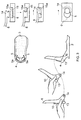
- a first embodiment is illustrated of a binding 1 for a snowboard according to the present invention, viewed from above and from the side, where the binding 1 is composed of a receiver part 2 and a locking part (not shown) for a snowboarder's boot (not shown).
- the receiver part 2 is then designed for receiving the boot (not shown), where the locking part (not shown) is then employed for securing or releasing the boot with respect to the binding 1.
- the receiver part 2 is further provided with a surface 3 which has to be connected with the top of the snowboard in a suitable manner, for example by means of various attachment devices such as screws, bolts, double-sided tape etc., in order thereby to form a fixed connection between the binding 1 and the snowboard (not shown).
- the receiver part 2 may comprise an adjustment device (not shown), thereby enabling the binding's 1 position to be adjusted relative to the snowboard's longitudinal axis.
- the receiver part 2 further comprises a loop 4, a so-called heel cup, which is intended to abut against the heel of the boot when the boot is locked in the binding 1.
- the loop 4 is provided with two recesses 5, formed diametrically opposite each other, where these recesses 5 extend from the top 9 of the loop 4 a distance down into the receiver part 2 towards the top of the snowboard.
- a detachable calf support (a so-called highback) 6 will then be provided with protruding portions 7 which are complementary to the recesses 5 in the loop 4, thereby enabling the detachable calf support 6 to be attached or connected to the receiver part 2 by means of the recesses 5 and the protruding portions 7.
- a lower surface 8 of the detachable calf support 6 will be provided complementarily with the top 9 of the loop 4, with the result that the lower surface 8 of the detachable calf support 6 will abut against the top 9 of the loop 4 when the detachable calf support 6 is connected to the receiver part 2, as illustrated on the right side of figure 1 .
- detachable calf support 6 On the left side of figure 1 it is shown how the detachable calf support 6 is attached or connected to the receiver part 2.
- the detachable calf support 6 will then be arranged in a forward-facing position, thereby enabling the protruding portions 7 to be inserted into the recesses 5 in the loop 4.
- the detachable calf support 6, with the protruding portions 7 inserted into the recesses 5, will then be rotated towards the loop 4, with the result that the lower surface 8 of the detachable calf support 6 is brought into abutment against the top 9 of the loop 4, as illustrated on the right side of figure 1 .
- the recesses 5 in the loop 4 must be of such a shape that they permit the detachable calf support 6 to be adjusted relative to the loop 4 by means of an adjusting device 10, in order thereby to fit the detachable calf support 6 against the back of a snowboarder's calf, as well as to permit the detachable calf support 6 to be rotated forwards and down against the top of the snowboard, thereby making the snowboard more compact during transport and storage.
- Another alternative is to provide the detachable calf support 6 resilient or elastic, this elasticity being employed for squeezing the protruding portions 7 together slightly, thereby enabling the protruding portions 7 to be inserted in the recesses 5 in the loop 4 in this compressed position.
- the detachable calf support 6 When the detachable calf support 6 is attached in the recesses 5, the detachable calf support 6 will attempt to reassume its original position (i.e. it will spring outwards), with the result that the detachable calf support will be secured in the recesses 5.
- the boot's position in the binding 1 will be defined by the inside of the loop (the heel cup), which will be sufficient for positioning the boot correctly in the binding 1, but in addition the receiver part 2 may be provided with protrusions or the like (not shown) in front of the recesses 5, in order to give further support to the boot in the binding 1.
- the detachable calf support 6 will be able to be removed from the binding's 1 receiver part 2 by means of a method which is the opposite of the insertion method.
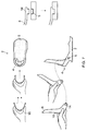
- Figures 2a and 2b illustrate two alternative embodiments of the binding 1 according to the present invention, viewed from above and from the side, where the receiver part's 2 loop 4 is provided with two recesses 5 arranged opposite each other, which recesses 5 are further connected with guide grooves 11 extending a length in the loop's 4 longitudinal direction.
- the recesses 5 and the guide grooves 11 will then be designed so as to interact with complementarily formed guide grooves 12 in the detachable calf support 6.
- the detachable calf support 6 When the detachable calf support 6 has to be connected to the receiver part 2, the detachable calf support 6 will be slightly compressed, thereby bringing the guide grooves 12 into contact with the recesses 5 in the loop 4, this being illustrated on the left side of figures 2a and 2b .
- the detachable calf support 6 will thereafter be released, whereby, on account of the detachable calf support's 6 elastic or resilient properties, the guide grooves 12 will bring the guide grooves 12 into contact with the guide grooves 11 in the loop 4. This is illustrated in the middle of figures 2a and 2b . Since the guide grooves 11 extend a certain length in the loop's 4 longitudinal direction, the detachable calf support 6 can now be pushed backwards towards the rear edge of the loop 4, in the direction of the arrow P, until the guide grooves 12 reach the end of the guide grooves 11. This is illustrated on the right side of figures 2a and 2b .
- the guide grooves 12 and the guide grooves 11 may, for example, be designed in a complementary shape, for example a T-shape or the like, in order to prevent the guide grooves 12 from "jumping" out of the guide grooves 11. It should be understood, however, that other shapes may also be employed for implementing this function.
- the detachable calf support 6 will comprise an adjusting mechanism 10 for permitting an adjustment of the detachable calf support 6 relative to the loop 4.
- the detachable calf support 6 and the guide grooves 12 may be provided as separate parts, whereupon they will be able to be rotated relative to each other via a bolt 8 or the like. This will mean that the detachable calf support 6 will be able to be folded down against the receiver part's 2 surface 3.
- the guide grooves 12 may be an integrated part of the detachable calf support 6, in which case the detachable calf support 6 is not capable of being folded down.
- Recesses 5 and guide grooves 11 will then be provided in the upper part 4a of the loop 4.
- the guide grooves 12 will be integrated in the detachable calf support 6, thereby preventing guide groove 12 and the detachable calf support 6 from being moved relative to each other.
- the detachable calf support 6 will be able to be removed from the binding's 1 receiver part 2 by means of a method which is opposite to the insertion method.
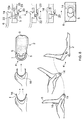
- Figure 3 illustrates yet another embodiment of the binding according to the present invention, viewed from above and from the side, where an inside of the loop (the heel cup) 4 is provided with a number of recesses 5a, in which recesses 5a a number of tongues 13 extending downwardly from the detachable calf support 6 are arranged when the detachable calf support 6 is connected to the binding's 1 receiver part 2.
- the loop 4 is further provided with two recesses 5 arranged opposite each other.
- the detachable calf support 6 will further be provided with two locking elements 14, where the locking elements 14 are locked in the recesses 5 in the loop 4.
- the detachable calf support 6 will first be connected to the loop 4 by the locking elements 14 being inserted in the recesses 5, whereupon the detachable calf support 6 is rotated down against the top 9 of the loop 4, with the result that the downwardly extending tongues 13 are placed in the recesses 5a on the inside of the loop 4.
- the right side of figure 3 shows details of the locking elements 14 and the recesses 5 in the loop.
- the recess 5 will comprise an opening which can receive the locking element 14, and a slot 15 extending from the opening, where the slot 15 comprises a locking lip 15a.
- the locking element 14 When the locking element 14 is inserted in the opening in the recess 5, the locking element 14 has to be moved inwards in the slot 15, in order to be locked against the locking lip 15a.
- the locking element 14 then has a shape which together with the locking lip 15a permits locking.
- the advantage of this embodiment is that during use the boot presses the tongues 13 of the detachable calf support 6 against the loop (the heel cup) 4, in order thereby to both lock and stiffen the detachable calf support 6.
- the detachable calf support 6 can be rotated forwards and folded down, but it can also be locked in a position with a slightly forward-leaning calf support.
- consideration must be given as to whether to be satisfied with a snap-in system without an extra locking mechanism, or whether to lock the detachable calf support 6 in or round the rotational point. At all events locking mechanisms are preferred which do not require the use of tools.
- Figure 4 illustrates an embodiment of the binding 1 according to the present invention, viewed from above and from the side, where the detachable calf support 6 is now mounted on the outside of the binding's 1 receiver part 2.
- the outside of the loop 4 will then be provided with two recesses 5 formed opposite each other, where the recesses 5 are arranged for receiving and locking of the detachable calf support's 6 two locking elements 14.
- Recesses 5 and locking elements 14 may be designed in a similar manner to that described in the embodiment illustrated in figure 3 . In this embodiment, however, the detachable calf support 6 will not be provided with the tongues 13 and the loop 4 will not be provided with the recesses 5a.
- the locking elements may also be formed to allow the calf support 6 to be adjusted through the locking elements 14.
- the calf support 6 By moving the calf support's 6 locking elements 14 in the recesses 5, the calf support 6 will rotate about the loop (heel cup) 4, whereby it is achieved an adjustment of the calf support 6 (forward lean).
- the locking elements 14 will then be designed to be located on a straight or curved line, where this forms an angle between 40 to 70 degrees with the binding's 1 surface 3, when the calf support 6 is inserted in the binding 1.
- the right side of figure 4 illustrates details of the locking elements 14 and the recesses 5 in the loop.
- the recess 5 will comprise an opening which can receive the locking element 14, and a slot 15 extending from the opening, where the slot 15 comprises a locking lip 15a.
- the locking element 14 When the locking element 14 is guided into the opening in the recess 5, the locking element 14 has to be moved inwards in the slot 15, in order to be locked against the locking lip 15a.
- the locking element 14 then has a shape which together with the locking lip 15a permits locking.
- the insertion in the rotational point (the recesses 5) is conducted in such a manner that when the calf presses the detachable calf support 6 backwards, the detachable calf support 6 cannot come loose.
- Figure 5 illustrates a further embodiment of the binding 1 according to the present invention, viewed from above and from the side, where the detachable calf support 6 in this embodiment is mounted on the inside of the loop 4.
- the loop 4, recesses 5 and locking elements 14 are designed, we refer to figure 4 , as these are identically designed.
- this embodiment when the detachable calf support 6 is removed, there will be a gap between the heel of the boot and the inside of the loop 4 (due to the fact that the detachable calf support 6 has a certain thickness), where this gap may cause the boot to be able to move in the binding 1.
- an insert I which insert I is also provided with locking elements 14, may be employed to replace the detachable calf support 6 when it is removed.
- the insert I will then be connected to the recesses 5 arranged on the inside of the loop 4.
- the insert I will further comprise a lip 16, where this lip 16 will abut against the loop's upper edge 9 when the insert I is correctly arranged in the loop 4.
- the recesses 5 which are described in connection with figures 4 and 5 , could also be designed such that they allow the calf support 6 to be adjusted through the recesses 5.
- the calf support 6 will rotate about the loop (heel cup) 4, whereby it is obtained an adjustment of the calf support (forward lean).
- the recesses 5 could then be designed to be located on a straight or curved line, where this forms an angle between 40 to 70 degrees with the binding's 1 surface 3.
- Figures 6 and 7 illustrate alternative embodiments of the detachable calf support's 6 locking elements 14 and the loop's 4 recesses 5 which are described in connection with figures 3 , 4 and 5 , where it should be understood that the detachable calf support 6 may be arranged on the outside or the inside of the loop 4, where the loop 4 may be provided with recesses 5a on the inside of the loop 4 and the detachable calf support 6 may be provided with downwardly extending tongues 13.
- the detachable calf support's 6 locking element 14 may be conical in shape, whereby the loop's 4 recess will also be in conical form.
- FIG. 7 illustrates an even simpler design of the detachable calf support's 6 locking elements 14, with correspondingly simpler recesses 5, the locking elements 14 and the recesses 5 being in the form of complementary circles, square or polygonal openings, where locking of the locking elements 14 in the recesses 5 is accomplished by the detachable calf support 6 and the insert I being squeezed together and guided into engagement with the recesses 5.
- their resilient or elastic properties will cause the locking elements 14 to be retained in engagement with the recesses 14.
- Figure 8 illustrates a similar embodiment of a binding according to the present invention to that depicted in figure 5 , but where the loop 4 comprises a locking device for preventing the detachable calf support 6 from inadvertently falling off. Since recesses 5 and locking elements 14 are designed in the same way as illustrated in figures 3 , 4 and 5 , we refer to the description of these figures. Only the locking device 20 will be explained here in greater detail.
- the locking device 20 is mounted on the outside of the loop 4, where a locking pin 21 in the locking device 20 extends through an opening 22 which is connected to the recess 5.
- the locking pin 21 When the detachable calf support's 6 locking element 14 is guided into the recess 5 in the loop 4, the locking pin 21 will be moved in the opening 22, whereby the locking element 14 is moved inwards in the slot 15, in order thereby to be locked against the locking lip 15a. In this position the locking element 14 will have been moved so far forward in the slot 15 that the locking pin 21, which is spring-loaded (not shown), will assume its original position (illustrated in the top picture on the right side), with the result that the locking pin 21 will abut against an end of the locking element 14 which is opposite an end of the locking element 14 which abuts against the locking lip 15a.
- the locking device 20 also comprises a release pin 23, which is used to bring the locking pin 21 out of abutment with the end of the locking element 14 when the detachable calf support 6 has to be removed from the loop 4.
- Figure 9 illustrates yet another embodiment of a binding according to the present invention, where the receiver part 2 can now be made with a thinner loop (heel cup) 4, in which case the thinner loop 4 is produced as a separate unit which can be connected in a suitable manner to the receiver part 2.
- the separate loop 4 may, for example, be made of a metal.
- the recess 5 in the loop 4 here will not be connected to a slot 15, but the locking elements 14 will be of a similar design to that illustrated, for example, in figure 5 .
Landscapes
- Orthopedics, Nursing, And Contraception (AREA)
Description
- The invention relates to bindings for mounting on a snowboard, where the bindings come in pairs and can be attached to the snowboard's attachment points. More specifically the present invention relates to bindings for snowboards which can easily be adapted to suit the snowboarder's equipment and riding style.
- Snowboarders will have different wishes on how the snowboard's binding(s) are to be adapted in order to provide the best riding experience seen in relation to that each snowboarder has his own special riding style. In addition, the bindings of the snowboard must be able to be adapted to the snowboarder's shoe size, the design of the shoe etc.
- Ordinary bindings for snowboards are provided with a loop behind the heel, referred to here as a heel cup, where in this loop or in connection therewith an additional support is attached, a so-called calf support or highback, where the calf support extends a certain distance upwards behind the snowboarder's calf, in order to improve the transfer of force from the snowboarder's calf to the snowboard when the snowboard is edged on the heel side. A heel cup with calf support mounted on the inside of the heel cup then together form the space or the arrangement which keep the snowboarder's boot/boots in the correct position in the binding. Forces or loads which arise during a snowboard ride can be quite substantial, thereby requiring a fairly robust construction for both binding and calf support.
- Almost all types of bindings allow for a certain regulation or adjustment of the calf support. Most common the calf support will comprise an adjustment device on its backside, such that the calf support can be angled relative to the binding's heel cup. The calf support will then be rotatable around its attachment points with the binding, where the attachment points of the calf support are arranged in an area near the snowboarder's ankle area. In this way the binding can be adapted to suit the snowboarder's riding style and/or skill, in addition to which the calf support will be rotatably mounted, thus enabling it to be folded down against the snowboard's binding, thereby providing a more compact snowboard during transport and/or storage.
- A commonly used standard for bindings employs a round plate which fixes the binding to the snowboard. This plate is conical and provided in the form of a gearwheel, thereby enabling the binding to be adjusted to the desired angle relative to the snowboard's longitudinal direction and locked at this angle when the plate is screwed on. There are also other newer methods for attaching bindings. The binding according to the present invention does not require any special kind of device for fastening it to the snowboard.
- Furthermore, the binding is made with fastening straps over the boots, which is normal for modern bindings, usually a fastening strap over the instep and one over the toes, but here too there is no special requirement for further attachment of the boot for the binding according to the present invention, as long as it is sufficiently strong.
- As an example of the prior art it shall be referred to
US 2007/0114763 A1 ,US 2007/0158929 A1 andUS 2008/0258434 A1 , where various bindings for snowboards are described. The bindings comprise a receiver part which is mounted on the snowboard and a locking part which is connected to the receiver part, where the locking part is used for securing or releasing the snowboard rider's boot with respect to the binding. The receiver part also comprises a calf support which is adjustable and/or rotatable, thereby enabling adjustment of the binding to be performed or securing or releasing of the snowboarder's boot to be facilitated. -
AT 409.937 B -
WO 2007/064889 A1 discloses a snowboard binding, where the binding comprises a base plate, a heel-cradling element, a toe-cradling element, an instep-strapping arrangement having a long part connected to one side of the base plate and a short side part connected to the other side, a closure device for the instep-strapping arrangement, and a flexible linkage connecting the closure device of the instep-strapping arrangement and the toe-cradling element. - The above-cited publications describe different solutions where a calf support forms a part of the actual binding and is therefore not intended to be removed from the binding's receiver part. This means that the binding can only be used for a specific type of snowboarding, with the result that the binding has to be replaced when performing another type of snowboarding.
- It is an object of the present invention to provide a binding for a snowboard which permits replacement of the binding's calf support, thereby enabling the snowboard to be used for several types of snowboarding (with and without calf support), a different calf support (short, medium or long), etc., where the binding requires minimal or no adjustments after removal of the calf support. This is achieved by means of a snowboard binding as specified in the independent patent claim. Further embodiments of the present invention are indicated in the dependent patent claims.
- It is a further object of the present invention to provide a binding for a snowboard which allow for adjustment or adaptation of the binding to the snowboarder's riding style and equipment.
- A new trend has now appeared where snowboarding is skating-oriented, and it is more interesting to have a lower binding. The present invention is based on the known type of snowboard binding, but where the snowboard binding according to the present invention is designed in such a manner that the binding can also be employed without the calf support, while still retaining the ability of the binding to position the boot correctly in the binding without the use of the calf support. The main principle is that a calf support is provided which can easily be removed, and where the binding should still be able to position the boot correctly in the binding without further adaptation (adjustment forwards or backwards on the snowboard).The calf support should preferably be able to be removed and replaced in again without the use of tools.
- The present invention relates to a binding for a snowboard, where the binding is attached to the snowboard by means of one or more devices, where the binding comprises a receiver part which is mounted to the snowboard and at least one locking part which is connected to the receiver part, thereby enabling a snowboarder's boot to be attached to the binding, where the binding is designed to be able to be used both with and without a calf support, where the binding has a simple device for inserting of the calf support, with the result that the calf support is easy to remove from and be attached to the binding, where the binding furthermore will have approximately the same fit and position for the boot with and without the use of the calf support, so that the binding will still position the snowboarder's boot correctly in the binding without adjusting its position on the snowboard. In addition, the binding comprises adjusting devices in order to be able to adjust the angle the calf support forms with the binding (so-called forward lean).
- An embodiment of the binding according to the present invention provides a binding which, after removal of the calf support, still locks the boots approximately in the same position as when the calf support was inserted. By means of various attachment devices, the calf support will then be connected to the binding's heel cup, in the actual heel cup, in a sufficiently secure manner, while simultaneously retaining enough "filling" in the heel cup for the snowboarder's boot to be held in approximately the same position when the calf support is removed. The binding according to this embodiment will then comprise a detachable calf support, where there will be no need to insert a device for filling the "gap" in the heel cup after the detachable calf support has been removed, for example when riding without calf support. The binding's heel cup will then be so strong and thick that the heel cup will be provided with a number of attachment devices in the form of openings and/or recesses in its material, to enable it to be employed for attachment and support of the detachable calf support. The detachable calf support will then be provided in a similar manner with attachment devices matching the attachment devices provided in the heel cup.
- The binding according to the present invention may therefore be envisaged provided with many different types of attachment devices, but the attachment devices should be designed in such a manner that they still permit the detachable calf support to be rotated forwards, after having been attached to the heel cup. This can be achieved either by the detachable calf support being attached to the heel cup about two rotational points, which rotational points also form the calf supports attachment devices, where each rotational point is arranged on each side of the boot in an area round the snowboarder's ankle, when the snowboarder's boots are connected to the bindings, such that the detachable calf support rotates about these two rotational points, or by letting the heel cup to form the calf support's rotational point, whereby the attachment device's then will be used as adjusting devices for the calf support.
- Another embodiment of the binding according to the present invention provides a binding, where, when it is attached to the heel cup, a detachable calf support is arranged on the inside of the binding's heel cup, and on removal of the detachable calf support a "gap" is left between the inside of the heel cup and the heel of the boot, with the result that the boot is wrongly positioned in the binding (the boot will be able to be moved backwards and forwards in the binding) unless a replacement for the calf support is inserted internally in the heel cup. A replacement (insert), which fills the gap between the heel cup and the heel of the boot after the detachable calf support has been removed, will then be able to be connected to the binding's heel cup by means of the same fastening devices which are used for connecting the detachable calf support to the binding, with the result that the replacement provides a correct positioning of the boot in the binding.
- The calf supports may then be designed in different ways, where, for example, the calf support may be of a longer or shorter length, designed to be connected in the actual heel cup in the binding, on the inside or the outside of the heel cup, with different attachment devices etc.
- The attachment devices which are provided in the heel cup, where in some embodiments of the present invention the attachment devices will also form the rotational point for the detachable calf support, are mounted on the side of the heel cup in an area round the snowboarder's ankle when the boot is connected to the binding. According to the present invention the attachment devices may be mounted internally, externally or also on the top of the heel cup.
- For the embodiment where the attachment devices (and/or the rotational point) are mounted on the top of the heel cup, when the detachable calf support is removed, it will be important for the heel cup to be designed with sufficient thickness to keep the boot in the same place in the binding as the boot assumes when the detachable calf support is connected to the heel cup.
- In order to achieve the above, the heel cup must completely or partially fill the "gap" between it and the boot, either completely or piecemeal round the heel. Snowboard boots are usually so hard that they can cope with substantially reduced support for keeping them in place, as long as they have certain surfaces to abut or rest against at certain intervals. We should mention, however, that snowboarders travel in lifts with only one boot in the binding, so that the detachable calf support has to be well secured, and it may therefore be expedient to include locking mechanisms which prevent the detachable calf support from falling off.
- For the embodiment where the attachment devices (and/or the rotational point) are mounted on the inside of the heel cup, a different principle is employed for achieving a simple replacement of the detachable calf support. Only in this embodiment, when the detachable calf support is connected to the heel cup, will the detachable calf support fill the inside of the heel cup (the detachable calf support will be arranged between the heel cup and the heel of the boot), where, when the detachable calf support is removed, the gap between the heel cup and the heel of the boot has to be replaced by an insert which exactly fills up this gap. In this embodiment the rotational point will preferably be internally in the heel cup on each side of the heel. The rotational point for the detachable calf support is also its principal attachment, but since the detachable calf support is attached on the inside of the heel cup, the detachable calf support will be pressed against the inside of the heel cup during use, thereby in addition being locked between the heel cup and the boot. This may be accomplished in many ways, but we have focussed here on attachment means which do not require the use of tools. Here too it may be expedient to include locking mechanisms which prevent the detachable calf support from falling off.
- The common feature of all the embodiments is that they can be combined with different embodiments of the detachable calf support. Everything from a full-height insert down to an insert which does not reach over the heel cup may be used. This is a part of the concept which entails making a binding with a selection of different calf supports, and involving a binding which can be used without calf support.
- Several embodiments of the present invention will now be explained with reference to the figures, in which
-
Figure 1 illustrates a first embodiment of a binding according to the present invention, where a replaceable calf support is inserted in a heel cup in the binding, viewed from above and from the side, -
Figure 2a illustrates a second embodiment of a binding according to the present invention, where the inside of the heel cup is provided with an insertion groove in the heel cup's longitudinal direction for receiving a replaceable calf support, -
Figure 2b illustrates a similar embodiment of the binding to that depicted infigure 2a , where in addition the heel cup is provided with a separate hinged part, -
Figure 3 illustrates a fourth embodiment of a binding according to the present invention, where the inside of the heel cup is provided with a number of recesses, -
Figure 4 illustrates yet another embodiment of a binding according to the present invention, where the outside of the heel cup is provided with recesses for insertion of a replaceable calf support, -
Figure 5 illustrates a sixth embodiment of a binding according to the present invention, where the inside of the heel cup is provided with recesses for insertion of a replaceable calf support, -
Figures 6 and7 illustrate similar embodiments of recesses on the inside of the heel cup to that depicted infigure 5 , -
Figure 8 illustrates a possible locking mechanism which may be employed for preventing the detachable calf support from falling off, and -
Figure 9 illustrates another embodiment of a binding according to the present invention. - In
figure 1 a first embodiment is illustrated of a binding 1 for a snowboard according to the present invention, viewed from above and from the side, where the binding 1 is composed of areceiver part 2 and a locking part (not shown) for a snowboarder's boot (not shown). Thereceiver part 2 is then designed for receiving the boot (not shown), where the locking part (not shown) is then employed for securing or releasing the boot with respect to the binding 1. Thereceiver part 2 is further provided with asurface 3 which has to be connected with the top of the snowboard in a suitable manner, for example by means of various attachment devices such as screws, bolts, double-sided tape etc., in order thereby to form a fixed connection between the binding 1 and the snowboard (not shown). In addition thereceiver part 2 may comprise an adjustment device (not shown), thereby enabling the binding's 1 position to be adjusted relative to the snowboard's longitudinal axis. Thereceiver part 2 further comprises aloop 4, a so-called heel cup, which is intended to abut against the heel of the boot when the boot is locked in the binding 1. Theloop 4 is provided with tworecesses 5, formed diametrically opposite each other, where theserecesses 5 extend from thetop 9 of theloop 4 a distance down into thereceiver part 2 towards the top of the snowboard. A detachable calf support (a so-called highback) 6 will then be provided with protruding portions 7 which are complementary to therecesses 5 in theloop 4, thereby enabling thedetachable calf support 6 to be attached or connected to thereceiver part 2 by means of therecesses 5 and the protruding portions 7. In addition alower surface 8 of thedetachable calf support 6 will be provided complementarily with thetop 9 of theloop 4, with the result that thelower surface 8 of thedetachable calf support 6 will abut against thetop 9 of theloop 4 when thedetachable calf support 6 is connected to thereceiver part 2, as illustrated on the right side offigure 1 . - On the left side of
figure 1 it is shown how thedetachable calf support 6 is attached or connected to thereceiver part 2. Thedetachable calf support 6 will then be arranged in a forward-facing position, thereby enabling the protruding portions 7 to be inserted into therecesses 5 in theloop 4. Thedetachable calf support 6, with the protruding portions 7 inserted into therecesses 5, will then be rotated towards theloop 4, with the result that thelower surface 8 of thedetachable calf support 6 is brought into abutment against thetop 9 of theloop 4, as illustrated on the right side offigure 1 . - The
recesses 5 in theloop 4, however, must be of such a shape that they permit thedetachable calf support 6 to be adjusted relative to theloop 4 by means of an adjustingdevice 10, in order thereby to fit thedetachable calf support 6 against the back of a snowboarder's calf, as well as to permit thedetachable calf support 6 to be rotated forwards and down against the top of the snowboard, thereby making the snowboard more compact during transport and storage. - When a boot is connected to the binding 1, the
detachable calf support 6 will be unable to fall off, due to the fact that the boot, which abuts against the inside of thedetachable calf support 6, will prevent thedetachable calf support 6 from rotating about therecesses 5 in theloop 4, but to prevent thedetachable calf support 6 from coming loose from therecesses 5 in theloop 4 when there is no boot in the binding 1, a locking mechanism (not shown) may be provided in the loop's 4recesses 5, which locking mechanism may either be designed so as to press against the protruding portions 7 of thedetachable calf support 6, about their rotational point, or there may be a locking mechanism which prevents the protruding portions 7 from sliding out of therecesses 5 in theloop 4. Another alternative is to provide thedetachable calf support 6 resilient or elastic, this elasticity being employed for squeezing the protruding portions 7 together slightly, thereby enabling the protruding portions 7 to be inserted in therecesses 5 in theloop 4 in this compressed position. When thedetachable calf support 6 is attached in therecesses 5, thedetachable calf support 6 will attempt to reassume its original position (i.e. it will spring outwards), with the result that the detachable calf support will be secured in therecesses 5. - A person skilled in the art will know how such a locking mechanism should be designed, and it will therefore not be further discussed here.
- When the
detachable calf support 6 is removed from theloop 4 in thereceiver part 2, the boot's position in the binding 1 will be defined by the inside of the loop (the heel cup), which will be sufficient for positioning the boot correctly in the binding 1, but in addition thereceiver part 2 may be provided with protrusions or the like (not shown) in front of therecesses 5, in order to give further support to the boot in the binding 1. - The
detachable calf support 6 will be able to be removed from the binding's 1receiver part 2 by means of a method which is the opposite of the insertion method. -
Figures 2a and2b illustrate two alternative embodiments of the binding 1 according to the present invention, viewed from above and from the side, where the receiver part's 2loop 4 is provided with tworecesses 5 arranged opposite each other, which recesses 5 are further connected withguide grooves 11 extending a length in the loop's 4 longitudinal direction. Therecesses 5 and theguide grooves 11 will then be designed so as to interact with complementarily formed guide grooves 12 in thedetachable calf support 6. When thedetachable calf support 6 has to be connected to thereceiver part 2, thedetachable calf support 6 will be slightly compressed, thereby bringing the guide grooves 12 into contact with therecesses 5 in theloop 4, this being illustrated on the left side offigures 2a and2b . - The
detachable calf support 6 will thereafter be released, whereby, on account of the detachable calf support's 6 elastic or resilient properties, the guide grooves 12 will bring the guide grooves 12 into contact with theguide grooves 11 in theloop 4. This is illustrated in the middle offigures 2a and2b . Since theguide grooves 11 extend a certain length in the loop's 4 longitudinal direction, thedetachable calf support 6 can now be pushed backwards towards the rear edge of theloop 4, in the direction of the arrow P, until the guide grooves 12 reach the end of theguide grooves 11. This is illustrated on the right side offigures 2a and2b . - The guide grooves 12 and the
guide grooves 11 may, for example, be designed in a complementary shape, for example a T-shape or the like, in order to prevent the guide grooves 12 from "jumping" out of theguide grooves 11. It should be understood, however, that other shapes may also be employed for implementing this function. - In a similar manner to the embodiment illustrated in
figure 1 , thedetachable calf support 6 will comprise anadjusting mechanism 10 for permitting an adjustment of thedetachable calf support 6 relative to theloop 4. - In a preferred embodiment of the present invention the
detachable calf support 6 and the guide grooves 12 may be provided as separate parts, whereupon they will be able to be rotated relative to each other via abolt 8 or the like. This will mean that thedetachable calf support 6 will be able to be folded down against the receiver part's 2surface 3. Alternatively, the guide grooves 12 may be an integrated part of thedetachable calf support 6, in which case thedetachable calf support 6 is not capable of being folded down. - In
figure 2b the rotation of the detachable calf support will be permitted by theactual loop 4 being in the form of a hinged element, where anupper part 4a of theloop 4 is connected via a bolt B or the like to alower part 4b of theloop 4. The bolt B will then form a rotational point for theupper part 4a of theloop 4, thereby enabling thedetachable calf support 6, which is connected to theupper part 4a of theloop 4, to be folded forwards against the receiver part's 2surface 3. -
Recesses 5 and guidegrooves 11 will then be provided in theupper part 4a of theloop 4. In this embodiment the guide grooves 12 will be integrated in thedetachable calf support 6, thereby preventing guide groove 12 and thedetachable calf support 6 from being moved relative to each other. - The
detachable calf support 6 will be able to be removed from the binding's 1receiver part 2 by means of a method which is opposite to the insertion method. -
Figure 3 illustrates yet another embodiment of the binding according to the present invention, viewed from above and from the side, where an inside of the loop (the heel cup) 4 is provided with a number ofrecesses 5a, in which recesses 5a a number oftongues 13 extending downwardly from thedetachable calf support 6 are arranged when thedetachable calf support 6 is connected to the binding's 1receiver part 2. Theloop 4 is further provided with tworecesses 5 arranged opposite each other. Thedetachable calf support 6 will further be provided with two lockingelements 14, where the lockingelements 14 are locked in therecesses 5 in theloop 4. In a similar manner to the embodiment according tofigure 1 , thedetachable calf support 6 will first be connected to theloop 4 by the lockingelements 14 being inserted in therecesses 5, whereupon thedetachable calf support 6 is rotated down against thetop 9 of theloop 4, with the result that the downwardly extendingtongues 13 are placed in therecesses 5a on the inside of theloop 4. The right side offigure 3 shows details of the lockingelements 14 and therecesses 5 in the loop. For the sake of simplicity, only right lockingelement 14 of thedetachable calf support 6, viewed in the snowboard's normal direction of travel, is illustrated inserted in arecess 5 on the right side (on the inside) of theloop 4. In this case therecess 5 will comprise an opening which can receive the lockingelement 14, and aslot 15 extending from the opening, where theslot 15 comprises a lockinglip 15a. When the lockingelement 14 is inserted in the opening in therecess 5, the lockingelement 14 has to be moved inwards in theslot 15, in order to be locked against the lockinglip 15a. The lockingelement 14 then has a shape which together with the lockinglip 15a permits locking. - The advantage of this embodiment is that during use the boot presses the
tongues 13 of thedetachable calf support 6 against the loop (the heel cup) 4, in order thereby to both lock and stiffen thedetachable calf support 6. In this embodiment also thedetachable calf support 6 can be rotated forwards and folded down, but it can also be locked in a position with a slightly forward-leaning calf support. In this case, as in all the other embodiments, consideration must be given as to whether to be satisfied with a snap-in system without an extra locking mechanism, or whether to lock thedetachable calf support 6 in or round the rotational point. At all events locking mechanisms are preferred which do not require the use of tools. -
Figure 4 illustrates an embodiment of the binding 1 according to the present invention, viewed from above and from the side, where thedetachable calf support 6 is now mounted on the outside of the binding's 1receiver part 2. The outside of theloop 4 will then be provided with tworecesses 5 formed opposite each other, where therecesses 5 are arranged for receiving and locking of the detachable calf support's 6 two lockingelements 14.Recesses 5 and lockingelements 14 may be designed in a similar manner to that described in the embodiment illustrated infigure 3 . In this embodiment, however, thedetachable calf support 6 will not be provided with thetongues 13 and theloop 4 will not be provided with therecesses 5a. - However, the locking elements may also be formed to allow the
calf support 6 to be adjusted through the lockingelements 14. By moving the calf support's 6locking elements 14 in therecesses 5, thecalf support 6 will rotate about the loop (heel cup) 4, whereby it is achieved an adjustment of the calf support 6 (forward lean). The lockingelements 14 will then be designed to be located on a straight or curved line, where this forms an angle between 40 to 70 degrees with the binding's 1surface 3, when thecalf support 6 is inserted in the binding 1. - The right side of
figure 4 illustrates details of the lockingelements 14 and therecesses 5 in the loop. For the sake of simplicity, only left lockingelement 14 of thedetachable calf support 6, viewed in the snowboard's normal direction of travel, is illustrated inserted in arecess 5 on the left side (on the outside) of theloop 4. In this case therecess 5 will comprise an opening which can receive the lockingelement 14, and aslot 15 extending from the opening, where theslot 15 comprises a lockinglip 15a. When the lockingelement 14 is guided into the opening in therecess 5, the lockingelement 14 has to be moved inwards in theslot 15, in order to be locked against the lockinglip 15a. The lockingelement 14 then has a shape which together with the lockinglip 15a permits locking. - The insertion in the rotational point (the recesses 5) is conducted in such a manner that when the calf presses the
detachable calf support 6 backwards, thedetachable calf support 6 cannot come loose. -
Figure 5 illustrates a further embodiment of the binding 1 according to the present invention, viewed from above and from the side, where thedetachable calf support 6 in this embodiment is mounted on the inside of theloop 4. For an explanation of how thedetachable calf support 6, theloop 4, recesses 5 and lockingelements 14 are designed, we refer tofigure 4 , as these are identically designed. In this embodiment, however, when thedetachable calf support 6 is removed, there will be a gap between the heel of the boot and the inside of the loop 4 (due to the fact that thedetachable calf support 6 has a certain thickness), where this gap may cause the boot to be able to move in the binding 1. In order to compensate for this gap, an insert I, which insert I is also provided with lockingelements 14, may be employed to replace thedetachable calf support 6 when it is removed. In a similar manner to thedetachable calf support 6, the insert I will then be connected to therecesses 5 arranged on the inside of theloop 4. The insert I will further comprise alip 16, where thislip 16 will abut against the loop'supper edge 9 when the insert I is correctly arranged in theloop 4. - In this case, as in all the other described embodiments, consideration must be given as to whether to be satisfied with a snap-in system without an extra locking mechanism, or whether to lock the
detachable calf support 6 in or round the rotational point (the recesses 5). At all events locking mechanisms are preferred which do not require the use of tools. - The
recesses 5 which are described in connection withfigures 4 and5 , could also be designed such that they allow thecalf support 6 to be adjusted through therecesses 5. By moving the calf support's 6locking elements 14 in therecesses 5, thecalf support 6 will rotate about the loop (heel cup) 4, whereby it is obtained an adjustment of the calf support (forward lean). Therecesses 5 could then be designed to be located on a straight or curved line, where this forms an angle between 40 to 70 degrees with the binding's 1surface 3. -
Figures 6 and7 illustrate alternative embodiments of the detachable calf support's 6locking elements 14 and the loop's 4recesses 5 which are described in connection withfigures 3 ,4 and5 , where it should be understood that thedetachable calf support 6 may be arranged on the outside or the inside of theloop 4, where theloop 4 may be provided withrecesses 5a on the inside of theloop 4 and thedetachable calf support 6 may be provided with downwardly extendingtongues 13. Infigure 6 the detachable calf support's 6locking element 14 may be conical in shape, whereby the loop's 4 recess will also be in conical form. Thedetachable calf support 6 and/or the insert will then be compressed, in order thereby to guide thelocking elements 14 into engagement with therecesses 5, whereupon thelocking elements 14 are moved in therecesses 5, in order to be locked thereto.Figure 7 illustrates an even simpler design of the detachable calf support's 6locking elements 14, with correspondinglysimpler recesses 5, the lockingelements 14 and therecesses 5 being in the form of complementary circles, square or polygonal openings, where locking of the lockingelements 14 in therecesses 5 is accomplished by thedetachable calf support 6 and the insert I being squeezed together and guided into engagement with therecesses 5. When thedetachable calf support 6 or the insert I is released, their resilient or elastic properties will cause thelocking elements 14 to be retained in engagement with therecesses 14. -
Figure 8 illustrates a similar embodiment of a binding according to the present invention to that depicted infigure 5 , but where theloop 4 comprises a locking device for preventing thedetachable calf support 6 from inadvertently falling off. Sincerecesses 5 and lockingelements 14 are designed in the same way as illustrated infigures 3 ,4 and5 , we refer to the description of these figures. Only thelocking device 20 will be explained here in greater detail. The lockingdevice 20 is mounted on the outside of theloop 4, where a lockingpin 21 in thelocking device 20 extends through anopening 22 which is connected to therecess 5. When the detachable calf support's 6locking element 14 is guided into therecess 5 in theloop 4, the lockingpin 21 will be moved in theopening 22, whereby the lockingelement 14 is moved inwards in theslot 15, in order thereby to be locked against the lockinglip 15a. In this position the lockingelement 14 will have been moved so far forward in theslot 15 that the lockingpin 21, which is spring-loaded (not shown), will assume its original position (illustrated in the top picture on the right side), with the result that the lockingpin 21 will abut against an end of the lockingelement 14 which is opposite an end of the lockingelement 14 which abuts against the lockinglip 15a. The lockingdevice 20 also comprises arelease pin 23, which is used to bring the lockingpin 21 out of abutment with the end of the lockingelement 14 when thedetachable calf support 6 has to be removed from theloop 4. -
Figure 9 illustrates yet another embodiment of a binding according to the present invention, where thereceiver part 2 can now be made with a thinner loop (heel cup) 4, in which case thethinner loop 4 is produced as a separate unit which can be connected in a suitable manner to thereceiver part 2. Theseparate loop 4 may, for example, be made of a metal. In addition, therecess 5 in theloop 4 here will not be connected to aslot 15, but thelocking elements 14 will be of a similar design to that illustrated, for example, infigure 5 .
Claims (11)
- Binding (1) for mounting on a snowboard, where the binding (1) is attachable to the snowboard by one or more attachment devices, wherein the binding (1) comprises a detachable calf support (6) wherein a receiver part (2) of the binding (1) comprises a loop (4) provided with recesses (5), which recesses (5) are formed to take up the detachable calf support (6), characterised in that the binding further comprises an insert such that the binding (1) will have approximately the same fit and position for a boot either with the detachable calf support (6), or without the calf support (6), this being achieved by: (a) sufficient support remaining for the boot in the loop (4) without the calf support (6), or (b) by the calf support (6) easily can be removed and replaced with the insert (I) which will fill up as much on an inside of the loop (4) as the detachable calf support (6) does.
- Binding (1) for mounting on a snowboard according to claim 1,
characterised in that the detachable calf support (6) is positioned within the binding's loop (4), so that when the detachable calf support (6) is removed, the insert (I) will have a same function to fill a gap in the loop (4), so that the boot fits equally well into the binding (1) even without the detachable calf support (6). - Binding (1) for mounting on a snowboard according to claim 1,
characterised in that the detachable calf support (6) only extends piecemeal down on the inside of the loop (4), so that when the detachable calf support (6) is removed, no insert (I) is required on the inside of the loop (4) in order to keep the boot in approximately the same place as it had while the detachable calf support (6) was in position. - Binding (1) for mounting on a snowboard according to one or more of the preceding claims 1-3,
characterised in that binding (1) comprises an own locking mechanism which prevents the detachable calf support (6) from falling out. - Binding (1) for mounting on a snowboard according to one or more of the preceding claims 1-4,
characterised in that the detachable calf support (6) is attached by a snap-in system based on the principle that the detachable calf support (6) is stiff enough to keep itself in position when it is inserted and soft enough to enable it to be removed and inserted by hand. - Binding (1) for mounting on a snowboard according to one or more of the preceding claims 1-5,
characterised in that the detachable calf support (6) can be removed and inserted without the use of tools. - Binding (1) for mounting on a snowboard according to one or more of preceding claims 1-6,
characterised in that the detachable calf support (6) can be adjusted by a certain forward angle with rotation about the loop (4) by adjusting fastening point of the detachable calf support (6) in the recesses (5), substantially radially on a rotation point. - Binding (1) for mounting on a snowboard according to claim 1 or 7,
characterised in that the detachable calf support (6) can be folded down forward in the binding (1). - Binding (1) for mounting on a snowboard according to claim 1,
characterised in that the loop (4) can be adjusted in the shoe's longitudinal direction in the binding (1) before the shoe is inserted. - Binding (1) for mounting on a snowboard according to one or more of the preceding claims 1-9,
characterised in that the binding (1) is provided with an adjustable strap or cap over the toes to hold the boot in position. - Binding (1) for mounting on a snowboard according to one or more of the preceding claims 1-10,
characterised in that the binding (1) is provided with an adjustable strap or cap over the instep of the foot in order to hold the boot in position.
Applications Claiming Priority (2)
| Application Number | Priority Date | Filing Date | Title |
|---|---|---|---|
| NO20110226 | 2011-02-08 | ||
| PCT/NO2012/000012 WO2012108773A2 (en) | 2011-02-08 | 2012-01-26 | Replaceable calf support (highback) |
Publications (2)
| Publication Number | Publication Date |
|---|---|
| EP2673059A2 EP2673059A2 (en) | 2013-12-18 |
| EP2673059B1 true EP2673059B1 (en) | 2016-03-30 |
Family
ID=45815937
Family Applications (1)
| Application Number | Title | Priority Date | Filing Date |
|---|---|---|---|
| EP12708412.7A Not-in-force EP2673059B1 (en) | 2011-02-08 | 2012-01-26 | Replaceable calf support (highback) |
Country Status (2)
| Country | Link |
|---|---|
| EP (1) | EP2673059B1 (en) |
| WO (1) | WO2012108773A2 (en) |
Family Cites Families (5)
| Publication number | Priority date | Publication date | Assignee | Title |
|---|---|---|---|---|
| DE60142529D1 (en) | 2000-01-06 | 2010-08-19 | Burton Corp | Support device made of different materials |
| AT409937B (en) * | 2001-02-02 | 2002-12-27 | Innovationdesigncompany Produk | Snowboard binding |
| US8016315B2 (en) | 2005-09-30 | 2011-09-13 | Flow Sports, Inc. | Modular binding for sports board |
| US7494148B2 (en) * | 2005-11-30 | 2009-02-24 | E. I. Du Pont De Nemours And Company | Board binding |
| US20080258434A1 (en) | 2007-04-13 | 2008-10-23 | Krenn Thomas | Snowboard binding with rear step-in and securing of boot by toe element |
-
2012
- 2012-01-26 WO PCT/NO2012/000012 patent/WO2012108773A2/en active Application Filing
- 2012-01-26 EP EP12708412.7A patent/EP2673059B1/en not_active Not-in-force
Also Published As
| Publication number | Publication date |
|---|---|
| WO2012108773A2 (en) | 2012-08-16 |
| WO2012108773A9 (en) | 2013-01-17 |
| EP2673059A2 (en) | 2013-12-18 |
| WO2012108773A3 (en) | 2012-11-15 |
Similar Documents
| Publication | Publication Date | Title |
|---|---|---|
| US5660410A (en) | Strapless boot binding for snowboards | |
| US5354088A (en) | Boot binding coupling for snow boards | |
| US6742800B2 (en) | Snowboard binding system | |
| JP3176067B2 (en) | Cleat engagement mechanism for snowboard | |
| US7490859B2 (en) | Device for retaining a boot on a snowboard | |
| US6206402B1 (en) | Snowboard binding adjustment mechanism | |
| US9492730B2 (en) | Snowboard binding and boot | |
| US7357406B2 (en) | Ski boot sole, disengageable ski binding and combination thereof | |
| US10702762B2 (en) | Snowboard binding and boot | |
| US20110254239A1 (en) | Angle adjuster for snowboard binder | |
| US6581944B1 (en) | Snowboard binding | |
| JP2009518068A (en) | Binding with adjustable heel and cup frame | |
| US20070182130A1 (en) | Snowboard binding | |
| US6923454B2 (en) | Snowboard binding rotational mechanism | |
| US20010028153A1 (en) | Snowboard binding with conical adapter | |
| EP2673059B1 (en) | Replaceable calf support (highback) | |
| EP1027112A1 (en) | Step-in ski and snowboard binding system | |
| JP2009022769A (en) | Universal binding apparatus | |
| US9114304B2 (en) | Quick release ski binding mounting system | |
| US20150360117A1 (en) | Snowboard Binding System | |
| US11130045B2 (en) | Fastening device for fastening a boot to a sliding board | |
| JPH0924132A (en) | Device which keeps shoes to sliding board for snow surfing | |
| US7232146B2 (en) | Snowboard binding | |
| EP3445461B1 (en) | Releaseable binding assembly for various sports | |
| WO2024027861A1 (en) | Splitboard binding base with means for attachment thereof to the skis |
Legal Events
| Date | Code | Title | Description |
|---|---|---|---|
| PUAI | Public reference made under article 153(3) epc to a published international application that has entered the european phase |
Free format text: ORIGINAL CODE: 0009012 |
|
| 17P | Request for examination filed |
Effective date: 20130906 |
|
| AK | Designated contracting states |
Kind code of ref document: A2 Designated state(s): AL AT BE BG CH CY CZ DE DK EE ES FI FR GB GR HR HU IE IS IT LI LT LU LV MC MK MT NL NO PL PT RO RS SE SI SK SM TR |
|
| DAX | Request for extension of the european patent (deleted) | ||
| 17Q | First examination report despatched |
Effective date: 20140901 |
|
| GRAP | Despatch of communication of intention to grant a patent |
Free format text: ORIGINAL CODE: EPIDOSNIGR1 |
|
| INTG | Intention to grant announced |
Effective date: 20150922 |
|
| GRAS | Grant fee paid |
Free format text: ORIGINAL CODE: EPIDOSNIGR3 |
|
| GRAA | (expected) grant |
Free format text: ORIGINAL CODE: 0009210 |
|
| AK | Designated contracting states |
Kind code of ref document: B1 Designated state(s): AL AT BE BG CH CY CZ DE DK EE ES FI FR GB GR HR HU IE IS IT LI LT LU LV MC MK MT NL NO PL PT RO RS SE SI SK SM TR |
|
| REG | Reference to a national code |
Ref country code: GB Ref legal event code: FG4D |
|
| REG | Reference to a national code |
Ref country code: CH Ref legal event code: EP |
|
| REG | Reference to a national code |
Ref country code: AT Ref legal event code: REF Ref document number: 784729 Country of ref document: AT Kind code of ref document: T Effective date: 20160415 |
|
| REG | Reference to a national code |
Ref country code: IE Ref legal event code: FG4D |
|
| REG | Reference to a national code |
Ref country code: DE Ref legal event code: R096 Ref document number: 602012016256 Country of ref document: DE |
|
| REG | Reference to a national code |
Ref country code: LT Ref legal event code: MG4D |
|
| PG25 | Lapsed in a contracting state [announced via postgrant information from national office to epo] |
Ref country code: FI Free format text: LAPSE BECAUSE OF FAILURE TO SUBMIT A TRANSLATION OF THE DESCRIPTION OR TO PAY THE FEE WITHIN THE PRESCRIBED TIME-LIMIT Effective date: 20160330 Ref country code: GR Free format text: LAPSE BECAUSE OF FAILURE TO SUBMIT A TRANSLATION OF THE DESCRIPTION OR TO PAY THE FEE WITHIN THE PRESCRIBED TIME-LIMIT Effective date: 20160701 Ref country code: NO Free format text: LAPSE BECAUSE OF FAILURE TO SUBMIT A TRANSLATION OF THE DESCRIPTION OR TO PAY THE FEE WITHIN THE PRESCRIBED TIME-LIMIT Effective date: 20160630 Ref country code: HR Free format text: LAPSE BECAUSE OF FAILURE TO SUBMIT A TRANSLATION OF THE DESCRIPTION OR TO PAY THE FEE WITHIN THE PRESCRIBED TIME-LIMIT Effective date: 20160330 |
|
| REG | Reference to a national code |
Ref country code: NL Ref legal event code: MP Effective date: 20160330 |
|
| REG | Reference to a national code |
Ref country code: AT Ref legal event code: MK05 Ref document number: 784729 Country of ref document: AT Kind code of ref document: T Effective date: 20160330 |
|
| PG25 | Lapsed in a contracting state [announced via postgrant information from national office to epo] |
Ref country code: RS Free format text: LAPSE BECAUSE OF FAILURE TO SUBMIT A TRANSLATION OF THE DESCRIPTION OR TO PAY THE FEE WITHIN THE PRESCRIBED TIME-LIMIT Effective date: 20160330 Ref country code: LT Free format text: LAPSE BECAUSE OF FAILURE TO SUBMIT A TRANSLATION OF THE DESCRIPTION OR TO PAY THE FEE WITHIN THE PRESCRIBED TIME-LIMIT Effective date: 20160330 Ref country code: SE Free format text: LAPSE BECAUSE OF FAILURE TO SUBMIT A TRANSLATION OF THE DESCRIPTION OR TO PAY THE FEE WITHIN THE PRESCRIBED TIME-LIMIT Effective date: 20160330 Ref country code: LV Free format text: LAPSE BECAUSE OF FAILURE TO SUBMIT A TRANSLATION OF THE DESCRIPTION OR TO PAY THE FEE WITHIN THE PRESCRIBED TIME-LIMIT Effective date: 20160330 |
|
| PG25 | Lapsed in a contracting state [announced via postgrant information from national office to epo] |
Ref country code: NL Free format text: LAPSE BECAUSE OF FAILURE TO SUBMIT A TRANSLATION OF THE DESCRIPTION OR TO PAY THE FEE WITHIN THE PRESCRIBED TIME-LIMIT Effective date: 20160330 |
|
| PG25 | Lapsed in a contracting state [announced via postgrant information from national office to epo] |
Ref country code: PL Free format text: LAPSE BECAUSE OF FAILURE TO SUBMIT A TRANSLATION OF THE DESCRIPTION OR TO PAY THE FEE WITHIN THE PRESCRIBED TIME-LIMIT Effective date: 20160330 Ref country code: EE Free format text: LAPSE BECAUSE OF FAILURE TO SUBMIT A TRANSLATION OF THE DESCRIPTION OR TO PAY THE FEE WITHIN THE PRESCRIBED TIME-LIMIT Effective date: 20160330 Ref country code: IS Free format text: LAPSE BECAUSE OF FAILURE TO SUBMIT A TRANSLATION OF THE DESCRIPTION OR TO PAY THE FEE WITHIN THE PRESCRIBED TIME-LIMIT Effective date: 20160730 |
|
| PG25 | Lapsed in a contracting state [announced via postgrant information from national office to epo] |
Ref country code: SK Free format text: LAPSE BECAUSE OF FAILURE TO SUBMIT A TRANSLATION OF THE DESCRIPTION OR TO PAY THE FEE WITHIN THE PRESCRIBED TIME-LIMIT Effective date: 20160330 Ref country code: ES Free format text: LAPSE BECAUSE OF FAILURE TO SUBMIT A TRANSLATION OF THE DESCRIPTION OR TO PAY THE FEE WITHIN THE PRESCRIBED TIME-LIMIT Effective date: 20160330 Ref country code: PT Free format text: LAPSE BECAUSE OF FAILURE TO SUBMIT A TRANSLATION OF THE DESCRIPTION OR TO PAY THE FEE WITHIN THE PRESCRIBED TIME-LIMIT Effective date: 20160801 Ref country code: AT Free format text: LAPSE BECAUSE OF FAILURE TO SUBMIT A TRANSLATION OF THE DESCRIPTION OR TO PAY THE FEE WITHIN THE PRESCRIBED TIME-LIMIT Effective date: 20160330 Ref country code: SM Free format text: LAPSE BECAUSE OF FAILURE TO SUBMIT A TRANSLATION OF THE DESCRIPTION OR TO PAY THE FEE WITHIN THE PRESCRIBED TIME-LIMIT Effective date: 20160330 Ref country code: RO Free format text: LAPSE BECAUSE OF FAILURE TO SUBMIT A TRANSLATION OF THE DESCRIPTION OR TO PAY THE FEE WITHIN THE PRESCRIBED TIME-LIMIT Effective date: 20160330 Ref country code: CZ Free format text: LAPSE BECAUSE OF FAILURE TO SUBMIT A TRANSLATION OF THE DESCRIPTION OR TO PAY THE FEE WITHIN THE PRESCRIBED TIME-LIMIT Effective date: 20160330 |
|
| PG25 | Lapsed in a contracting state [announced via postgrant information from national office to epo] |
Ref country code: BE Free format text: LAPSE BECAUSE OF FAILURE TO SUBMIT A TRANSLATION OF THE DESCRIPTION OR TO PAY THE FEE WITHIN THE PRESCRIBED TIME-LIMIT Effective date: 20160330 Ref country code: IT Free format text: LAPSE BECAUSE OF FAILURE TO SUBMIT A TRANSLATION OF THE DESCRIPTION OR TO PAY THE FEE WITHIN THE PRESCRIBED TIME-LIMIT Effective date: 20160330 |
|
| REG | Reference to a national code |
Ref country code: DE Ref legal event code: R097 Ref document number: 602012016256 Country of ref document: DE |
|
| PG25 | Lapsed in a contracting state [announced via postgrant information from national office to epo] |
Ref country code: DK Free format text: LAPSE BECAUSE OF FAILURE TO SUBMIT A TRANSLATION OF THE DESCRIPTION OR TO PAY THE FEE WITHIN THE PRESCRIBED TIME-LIMIT Effective date: 20160330 |
|
| PLBE | No opposition filed within time limit |
Free format text: ORIGINAL CODE: 0009261 |
|
| STAA | Information on the status of an ep patent application or granted ep patent |
Free format text: STATUS: NO OPPOSITION FILED WITHIN TIME LIMIT |
|
| 26N | No opposition filed |
Effective date: 20170103 |
|
| PG25 | Lapsed in a contracting state [announced via postgrant information from national office to epo] |
Ref country code: SI Free format text: LAPSE BECAUSE OF FAILURE TO SUBMIT A TRANSLATION OF THE DESCRIPTION OR TO PAY THE FEE WITHIN THE PRESCRIBED TIME-LIMIT Effective date: 20160330 |
|
| REG | Reference to a national code |
Ref country code: CH Ref legal event code: PL |
|
| GBPC | Gb: european patent ceased through non-payment of renewal fee |
Effective date: 20170126 |
|
| PG25 | Lapsed in a contracting state [announced via postgrant information from national office to epo] |
Ref country code: MC Free format text: LAPSE BECAUSE OF FAILURE TO SUBMIT A TRANSLATION OF THE DESCRIPTION OR TO PAY THE FEE WITHIN THE PRESCRIBED TIME-LIMIT Effective date: 20160330 |
|
| REG | Reference to a national code |
Ref country code: FR Ref legal event code: ST Effective date: 20170929 |
|
| PG25 | Lapsed in a contracting state [announced via postgrant information from national office to epo] |
Ref country code: FR Free format text: LAPSE BECAUSE OF NON-PAYMENT OF DUE FEES Effective date: 20170131 Ref country code: LI Free format text: LAPSE BECAUSE OF NON-PAYMENT OF DUE FEES Effective date: 20170131 Ref country code: CH Free format text: LAPSE BECAUSE OF NON-PAYMENT OF DUE FEES Effective date: 20170131 |
|
| REG | Reference to a national code |
Ref country code: IE Ref legal event code: MM4A |
|
| PG25 | Lapsed in a contracting state [announced via postgrant information from national office to epo] |
Ref country code: GB Free format text: LAPSE BECAUSE OF NON-PAYMENT OF DUE FEES Effective date: 20170126 Ref country code: LU Free format text: LAPSE BECAUSE OF NON-PAYMENT OF DUE FEES Effective date: 20170126 |
|
| PG25 | Lapsed in a contracting state [announced via postgrant information from national office to epo] |
Ref country code: IE Free format text: LAPSE BECAUSE OF NON-PAYMENT OF DUE FEES Effective date: 20170126 |
|
| PG25 | Lapsed in a contracting state [announced via postgrant information from national office to epo] |
Ref country code: MT Free format text: LAPSE BECAUSE OF NON-PAYMENT OF DUE FEES Effective date: 20170126 |
|
| PG25 | Lapsed in a contracting state [announced via postgrant information from national office to epo] |
Ref country code: AL Free format text: LAPSE BECAUSE OF FAILURE TO SUBMIT A TRANSLATION OF THE DESCRIPTION OR TO PAY THE FEE WITHIN THE PRESCRIBED TIME-LIMIT Effective date: 20160330 |
|
| PG25 | Lapsed in a contracting state [announced via postgrant information from national office to epo] |
Ref country code: HU Free format text: LAPSE BECAUSE OF FAILURE TO SUBMIT A TRANSLATION OF THE DESCRIPTION OR TO PAY THE FEE WITHIN THE PRESCRIBED TIME-LIMIT; INVALID AB INITIO Effective date: 20120126 |
|
| PG25 | Lapsed in a contracting state [announced via postgrant information from national office to epo] |
Ref country code: BG Free format text: LAPSE BECAUSE OF FAILURE TO SUBMIT A TRANSLATION OF THE DESCRIPTION OR TO PAY THE FEE WITHIN THE PRESCRIBED TIME-LIMIT Effective date: 20160330 |
|
| REG | Reference to a national code |
Ref country code: DE Ref legal event code: R081 Ref document number: 602012016256 Country of ref document: DE Owner name: LOW PRESSURE STUDIO B. V., NL Free format text: FORMER OWNER: HITURN AS, RAUFOSS, NO |
|
| PG25 | Lapsed in a contracting state [announced via postgrant information from national office to epo] |
Ref country code: CY Free format text: LAPSE BECAUSE OF NON-PAYMENT OF DUE FEES Effective date: 20160330 |
|
| PG25 | Lapsed in a contracting state [announced via postgrant information from national office to epo] |
Ref country code: MK Free format text: LAPSE BECAUSE OF FAILURE TO SUBMIT A TRANSLATION OF THE DESCRIPTION OR TO PAY THE FEE WITHIN THE PRESCRIBED TIME-LIMIT Effective date: 20160330 |
|
| PG25 | Lapsed in a contracting state [announced via postgrant information from national office to epo] |
Ref country code: TR Free format text: LAPSE BECAUSE OF FAILURE TO SUBMIT A TRANSLATION OF THE DESCRIPTION OR TO PAY THE FEE WITHIN THE PRESCRIBED TIME-LIMIT Effective date: 20160330 |
|
| PGFP | Annual fee paid to national office [announced via postgrant information from national office to epo] |
Ref country code: DE Payment date: 20210225 Year of fee payment: 10 |
|
| REG | Reference to a national code |
Ref country code: DE Ref legal event code: R119 Ref document number: 602012016256 Country of ref document: DE |
|
| PG25 | Lapsed in a contracting state [announced via postgrant information from national office to epo] |
Ref country code: DE Free format text: LAPSE BECAUSE OF NON-PAYMENT OF DUE FEES Effective date: 20220802 |