EP3445461B1 - Releaseable binding assembly for various sports - Google Patents
Releaseable binding assembly for various sports Download PDFInfo
- Publication number
- EP3445461B1 EP3445461B1 EP17786656.3A EP17786656A EP3445461B1 EP 3445461 B1 EP3445461 B1 EP 3445461B1 EP 17786656 A EP17786656 A EP 17786656A EP 3445461 B1 EP3445461 B1 EP 3445461B1
- Authority
- EP
- European Patent Office
- Prior art keywords
- boot
- binding
- toe
- wedge
- ledge
- Prior art date
- Legal status (The legal status is an assumption and is not a legal conclusion. Google has not performed a legal analysis and makes no representation as to the accuracy of the status listed.)
- Active
Links
Images


Classifications
-
- A—HUMAN NECESSITIES
- A63—SPORTS; GAMES; AMUSEMENTS
- A63C—SKATES; SKIS; ROLLER SKATES; DESIGN OR LAYOUT OF COURTS, RINKS OR THE LIKE
- A63C10/00—Snowboard bindings
- A63C10/02—Snowboard bindings characterised by details of the shoe holders
- A63C10/10—Snowboard bindings characterised by details of the shoe holders using parts which are fixed on the shoe, e.g. means to facilitate step-in
- A63C10/106—Snowboard bindings characterised by details of the shoe holders using parts which are fixed on the shoe, e.g. means to facilitate step-in to the front and back of the shoe
-
- A—HUMAN NECESSITIES
- A43—FOOTWEAR
- A43B—CHARACTERISTIC FEATURES OF FOOTWEAR; PARTS OF FOOTWEAR
- A43B5/00—Footwear for sporting purposes
- A43B5/04—Ski or like boots
-
- A—HUMAN NECESSITIES
- A43—FOOTWEAR
- A43B—CHARACTERISTIC FEATURES OF FOOTWEAR; PARTS OF FOOTWEAR
- A43B5/00—Footwear for sporting purposes
- A43B5/04—Ski or like boots
- A43B5/0401—Snowboard boots
- A43B5/0403—Adaptations for soles or accessories with soles for snowboard bindings
-
- A—HUMAN NECESSITIES
- A43—FOOTWEAR
- A43B—CHARACTERISTIC FEATURES OF FOOTWEAR; PARTS OF FOOTWEAR
- A43B5/00—Footwear for sporting purposes
- A43B5/04—Ski or like boots
- A43B5/0427—Ski or like boots characterised by type or construction details
-
- A—HUMAN NECESSITIES
- A43—FOOTWEAR
- A43C—FASTENINGS OR ATTACHMENTS OF FOOTWEAR; LACES IN GENERAL
- A43C11/00—Other fastenings specially adapted for shoes
- A43C11/14—Clamp fastenings, e.g. strap fastenings; Clamp-buckle fastenings; Fastenings with toggle levers
- A43C11/1493—Strap fastenings having hook and loop-type fastening elements
-
- A—HUMAN NECESSITIES
- A63—SPORTS; GAMES; AMUSEMENTS
- A63C—SKATES; SKIS; ROLLER SKATES; DESIGN OR LAYOUT OF COURTS, RINKS OR THE LIKE
- A63C10/00—Snowboard bindings
- A63C10/02—Snowboard bindings characterised by details of the shoe holders
- A63C10/04—Shoe holders for passing over the shoe
- A63C10/06—Straps therefor, e.g. adjustable straps
-
- A—HUMAN NECESSITIES
- A63—SPORTS; GAMES; AMUSEMENTS
- A63C—SKATES; SKIS; ROLLER SKATES; DESIGN OR LAYOUT OF COURTS, RINKS OR THE LIKE
- A63C10/00—Snowboard bindings
- A63C10/02—Snowboard bindings characterised by details of the shoe holders
- A63C10/08—Toe or heel stirrups; Clamps
-
- A—HUMAN NECESSITIES
- A63—SPORTS; GAMES; AMUSEMENTS
- A63C—SKATES; SKIS; ROLLER SKATES; DESIGN OR LAYOUT OF COURTS, RINKS OR THE LIKE
- A63C10/00—Snowboard bindings
- A63C10/02—Snowboard bindings characterised by details of the shoe holders
- A63C10/10—Snowboard bindings characterised by details of the shoe holders using parts which are fixed on the shoe, e.g. means to facilitate step-in
-
- A—HUMAN NECESSITIES
- A63—SPORTS; GAMES; AMUSEMENTS
- A63C—SKATES; SKIS; ROLLER SKATES; DESIGN OR LAYOUT OF COURTS, RINKS OR THE LIKE
- A63C10/00—Snowboard bindings
- A63C10/14—Interfaces, e.g. in the shape of a plate
-
- A—HUMAN NECESSITIES
- A63—SPORTS; GAMES; AMUSEMENTS
- A63C—SKATES; SKIS; ROLLER SKATES; DESIGN OR LAYOUT OF COURTS, RINKS OR THE LIKE
- A63C10/00—Snowboard bindings
- A63C10/24—Calf or heel supports, e.g. adjustable high back or heel loops
-
- B—PERFORMING OPERATIONS; TRANSPORTING
- B63—SHIPS OR OTHER WATERBORNE VESSELS; RELATED EQUIPMENT
- B63B—SHIPS OR OTHER WATERBORNE VESSELS; EQUIPMENT FOR SHIPPING
- B63B32/00—Water sports boards; Accessories therefor
- B63B32/40—Twintip boards; Wakeboards; Surfboards; Windsurfing boards; Paddle boards, e.g. SUP boards; Accessories specially adapted therefor
- B63B32/45—Fixation means for feet of the board user, e.g. footstraps
- B63B32/47—Bindings, e.g. wakeboard bindings
Definitions
- Embodiments generally relate to releasable boot and binding assemblies for various sports, including but not limited to action sports such as kiteboarding, kitesurfing, wakeboarding, surfing, landboarding, splitboarding, and snowboarding.
- action sports such as kiteboarding, kitesurfing, wakeboarding, surfing, landboarding, splitboarding, and snowboarding.
- Binding systems are generally used to attach a user to an object, generally a planar object that is placed below their feet. Some action sports require a binding system that can quickly and easily be both inserted/attached as well as removed/released. Prior art binding systems that were easily released and inserted did not provide enough support to many users. Prior art binding systems that provided adequate support were not easily released and inserted.
- WO 99/15245 discloses a boot and binding for securing the boot to an upper surface of a ski or snowboard. The boot includes a receiving structure located at a heel portion and a toe portion that, in one variation, may be covered by a thin layer of flexible elastomeric material.
- EP 1033 085 discloses an active highback system for automatically adjusting a snowboard boot between a walking position and a riding position.
- EP 1247 552 disclose another boot suitable for snowboarding.
- Exemplary embodiments provide a releasable boot and binding system for use with various sports.
- a boot (100) and binding (200) combination for board sports as set out in claim 1 below.
- the heel retaining device could be a separate component that attaches to a traditional boot or it could be embedded within a portion of the boot.
- the bindings contain some type of toe strap, which can take on many forms.
- An exemplary embodiment would engage the toe of the boot with the toe strap first, then by lowering the heel of the boot the heel retaining device can engage with the binding. The boot could then be released by simply removing the toe strap and sliding the boot horizontally and forward (towards the toe side of a board).
- Embodiments of the invention are described herein with reference to illustrations that are schematic illustrations of idealized embodiments (and intermediate structures) of the invention. As such, variations from the shapes of the illustrations as a result, for example, of manufacturing techniques and/or tolerances, are to be expected. Thus, embodiments of the invention should not be construed as limited to the particular shapes of regions illustrated herein but are to include deviations in shapes that result, for example, from manufacturing.
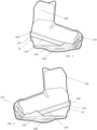
- FIGURE 1 provides a left side plan view of an exemplary embodiment of a boot 100 while engaged with an exemplary embodiment of the binding 200.
- the binding 200 contains a traditional slot 240 for mounting the binding 200 to a planar surface, typically a board of some type.
- a plate 250 may connect with the slot 240 and traverses underneath a small portion of the sole of the boot 100.
- a toe strap 220 is used to secure the toe portion of the boot 100.
- the binding 200 preferably contains a rear ledge or ledge 210, which is elevated above the top surface of the board and generally faces downwardly.
- the ledge 210 preferably engages with the heel retaining device 50 once the heel of the boot 100 has been lowered to a point where the heel retaining device 50 is below the ledge 210.
- the bindings 200 can have the traditional "high back” (as used in snowboarding and wakeboarding) or no high back (as shown in Figure 1 ). However, as shown and described further below, many different types of bindings could be used with the various embodiments herein, as the presence of a high back or lack of a high back can be effective with any embodiment depending on the application. In an exemplary embodiment, no high back would be used, only the arms 260 as shown and described below. It should also be noted that in a preferred embodiment, each element of the binding 200 is rigidly fixed relative to one another, with the exception of the toe strap 220.
- the ledge 210 should be rigidly fixed relative to the arm 260, which is rigidly fixed relative to the plate 250, making the ledge 210 also rigidly fixed relative to the plate 250. In this way, when the binding 200 is attached to a board, the ledge 210 should preferably not move relative to the top surface of the board 400.
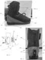
- FIGURE 2 provides a right side plan view of the embodiments shown in Figure 1 .
- the toe strap 220 preferably connects between two opposing sides of the binding 200 and is placed over the toe area of the boot 100. It should be noted that the toe strap 220 could wrap around the front surface of the toe of the boot 100, the top surface of the toe of the boot 100, or a combination of the top surface and the front surface of the toe of the boot 100 (as shown). Any version of the toe strap 220 would work with the exemplary embodiments herein.
- the plate 250 is shown extending under the toe and heel portions of the boot 100.
- FIGURE 3 provides a left side plan view of the embodiment of the boot 100 shown in Figures 1-2 .
- the boot 100 preferably contains a sole 110, a toe portion 111, a heel portion 112, and securing devices 125 which can be any combination of hook and loop fasteners, tightening clips, a traditional knot in laces, a boa system (cables which are tightened onto the user's foot by rotating a knob), or anything similar that could be used to secure the boot 100 onto the foot of a user.
- the sole 110 is smooth all around the perimeter with nothing protruding outwardly from the sole 110.
- An engagement surface 65 is located as the top surface of the heel retaining device 50, and engages with the ledge 210 on the binding 200 as shown and described herein.
- FIGURE 4 provides an exploded view of an exemplary embodiment of the heel retaining device 50.
- the wedge 60 contains the engagement surface 65 as described above and preferably contains a plurality of teeth on the back side of the wedge 60 to engage with a plurality of teeth which extend from the interior plate 70.
- the interior plate 70 is fixed relative to the boot 100 and may be effectively sewn into the boot 100.
- the interior plate 70 preferably contains a flat portion 71 which extends around the perimeter of a central portion 72 which extends rearwardly and contains the teeth which engage with the teeth on the back side of the wedge 60.
- the exterior boot wrap 105 may contain an aperture 106 which is sized to allow the central portion 72 of the interior plate 70 to be accessible.
- a female threaded fastener 75 may be fixed within the central portion 72 or may slide within a slot found in the central portion 72.
- the fastener 75 can be located at various vertical heights to account for the user's boot size/binding size combination, or other factors that could result in the boot 100 engaging with the binding 200 at different vertical heights.
- a male threaded fastener 66 may pass through the center of the wedge 60 to engage with the female threaded fastener 75.
- the opposing teeth of the wedge 60 and interior plate 70 become interlocked so that the wedge 60 can no longer move relative to the interior plate 70 (or the boot 100).
- the underside of the head of the male fastener 66 preferably contains the rear surface of the wedge 60, in order to draw the wedge 60 against the interior plate 70.
- the heel retaining device 50 is rigidly attached to the boot 100 so that the device 50 cannot substantially move relative to the boot 100 (other than the adjustment of the height of the cleat 60 by adjusting the fasteners 66/75) upon installation.
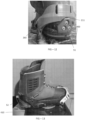
- FIGURE 5 provides a rear view of a boot 100 that includes the heel retaining device 50 shown in Figure 4 .
- the flat portion 71 of the interior plate 70 is preferably located behind/underneath the exterior boot wrap 105 while the aperture 106 allows access to the central portion 72 of the interior plate 70.
- the wedge can either be removed or can be re-located to a different vertical height by engaging with teeth on the wedge 60 and central portion 72 that are at different vertical heights.
- FIGURE 6 provides a rear perspective view of an exemplary embodiment of a boot 100 engaged with an exemplary embodiment of the binding 200, and indicating the location of section line A-A, which cuts horizontally through the center of the boot 100 and binding 200, along with the location of Detail A.
- a plate 250 which extends from the slots 240 and passes underneath a portion of the sole of the boot 100, but not the entire boot 100.
- An arm 260 preferably wraps behind the heel of the boot 100 and is attached to the plate 250, at a position close to the slots 240, on the left and right hand sides of the binding 200.
- a bottom surface of the arm 260 provides the ledge 210 for engagement with the engagement surface 65 on the wedge 60.
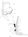
- FIGURE 7 provides a detailed section view taken along the section line A-A and indicating the features in Detail A.
- a bottom surface of the arm 260 provides the ledge 210 for engagement with the engagement surface 65 on the wedge 60.
- the angle ⁇ 2 is defined as the angle of the ledge 210 relative to a vertical axis 10 and rotated away from the rear of the boot 100. The angle ⁇ 2 will be described further below.
- FIGURE 8 provides a left side plan view of an exemplary embodiment of a heel retaining device 50.
- the wedge 60 also contains an engagement surface 65 at the top of the wedge 60.
- the angle ⁇ 1 is defined as the angle of the engagement surface 65 relative to a vertical axis 10 and rotated away from the rear of the boot 100.
- the engagement surface 65 can be substantially horizontal (i.e. ⁇ 1 is approximately 90 degrees from the vertical axis 10). However, in a preferred embodiment, the engagement surface 65 would have ⁇ 1 between 80 degrees and 85 degrees rearwardly away from the vertical axis 10.
- ⁇ 1 whatever angle is chosen for ⁇ 1 would also be the preferred angle for ⁇ 2 , or at least making ⁇ 1 substantially equal to ⁇ 2 or within a few degrees of each other. This is not required however, as some embodiments could use different values for the two, as an example, 80 degrees for ⁇ 1 with 90 degrees for ⁇ 2 . Generally speaking, ⁇ 1 and/or ⁇ 2 could be anywhere between 60 degrees and 90 degrees in various embodiments, depending on the application.
- the engagement surface 65 is upwardly facing as shown and would be fixed relative to the boot so that the engagement surface 65 does not move relative to the boot 100. As shown and described herein, the engagement surface 65 should prevent an upward vertical movement of the boot 100 relative to the binding 200, but would not substantially prevent forward horizontal movement of the boot 100 relative to the binding 200.
- the bottom portion of the wedge 60 contains a transition portion 57 which begins at the lowest point on the wedge 60 and continues upwardly until the full width of the wedge 60 has been reached.
- the cross-sectional thickness 56 increases as you move upwardly towards the engagement surface 65.
- the transition portion 57 begins at zero and then increases to 56A.
- the cross-sectional thickness increases to 56B.
- the cross-sectional thickness of the transition portion 57 becomes substantially equal to the cross-sectional thickness of the wedge 60, which is shown as 56C.
- transition portion 57 can take on any number of different shapes, including a triangular or trapezium shape. All that is required is that the transition portion 57 increases in cross-sectional thickness as you move upwardly towards the engagement surface 65.
- FIGURE 9 provides a perspective illustration of another embodiment of the binding 200.
- the plate 250 only passes underneath a small toe portion of the boot 100, where otherwise the boot 100 is resting atop the board surface 400 for all other areas of the boot 100, once engaged with the binding 200.
- this embodiment includes a notch 211 within the arm 260 of the binding 200, to further secure the heel retaining device 50 within the binding 200.
- the notch 211 can add some lateral strength to the connection between the boot 100 and binding 200, if necessary.
- FIGURES 10A through 10D provide a sequence of illustrations showing one embodiment for engaging the boot 100 within the binding 200.
- the toe of the boot 100 is inserted under a portion of the toe strap 220, which can take on many forms.
- a traditional ratchet strap (shown here) could be used, or a basic semi-rigid strap, or an elastomeric strap.
- the toe of the boot 100 when the toe of the boot 100 is inserted into the toe strap 220, the toe of the boot 100 can simply be slipped under the toe strap 220 without needing to ratchet (or otherwise tighten) the toe strap 220.
- the heel of the boot 100 is lowered until the heel retaining device 50 engages with the ledge 210.
- the heel retaining device 50 would preferably slip past the arm 260 while the heel of the boot 100 is lowered, but would extend rearwardly once it has passed the ledge 210 on the arm 260, so that the top portion of the heel retaining device 50 is adjacent to (and possibly contacting) the ledge 210. Once inserted, the top portion of the heel retaining device 50 may contact the ledge 210 when there is an upward movement by the user, but the boot 100 would be retained within the binding 200.
- FIGURES 11A through 11D provide a sequence of illustrations showing one embodiment for disengaging the boot 100 from the binding 200.
- the toe strap 220 can be removed or disengaged, and the boot 100 can slide laterally (horizontally) forward to slide the heel retaining device 50 underneath the ledge 210.
- the toe strap 220 could be removed in a number of ways, depending on the precise type of toe strap 220 that is selected.
- the wedge 60 can be described as constraining the vertical movement of the boot 100 relative to the binding 200, but does not constrain the horizontal or forward movement of the boot 100 relative to the binding 200 in a substantial way. This movement is restrained mostly by the toe strap 220 alone, in an exemplary embodiment.
- FIGURE 12 provides a rear perspective view of another embodiment of the heel retaining device 51 and binding 200.
- this embodiment is attached through a series of fasteners and contains a shape at the top of the device 51 which matches the shape used by the notch 211, in order to further secure the device 51 into the arm 260 of the binding 200.
- notch 211 is sized and shaped similar to the top portion of the heel retaining device 51, which here is a wedge with a pyramid shaped top portion
- FIGURE 13 provides a left side plan view of another embodiment of the heel retaining device 52 and binding.
- this embodiment of the binding 200 does not contain the slots for mounting, but instead has the traditional snowboarding mounting holes in the center of the binding.
- an intermediary element 410 has been placed between the board surface 400 and the binding 200.
- the heel retaining device 52 is made of a flexible material so that it can deform slightly in order to slip past the arm 260 when inserting the boot 100 into the binding 200.
- thin sheet metal has been used, but other flexible plastics, polymers, and composites could also be used.
- This embodiment of the heel retaining device 52 is simply attached to the heel portion of a traditional boot, without having to sew the device 52 into the exterior wrap of the boot.
- FIGURE 14 provides a right side plan view of several alternative embodiments for the wedge.
- the heel retaining device could be a solid feature and could be comprised of any rigid or semi-rigid material including but not limited to plastics (sometimes filled with glass or other types of strengthening fibers), metals, and composites.
- the wedge may have some flexibility, to aid insertion of the boot into the bindings (as described below) but this is not required at all.
- the heel retaining devices are comprised of a material that will not rust, rot, or otherwise degrade in water or substantially degrade from UV exposure, but this is not required.
- the heel retaining device is substantially rigid and does not have much flexibility, other than the flex of the boot itself.
- the flex of the boot itself provides the ability for the heel retaining device to slip past the arm of the binding (or for the wedge to slip past the ledge on the binding).
Landscapes
- Health & Medical Sciences (AREA)
- General Health & Medical Sciences (AREA)
- Physical Education & Sports Medicine (AREA)
- Chemical & Material Sciences (AREA)
- Engineering & Computer Science (AREA)
- Combustion & Propulsion (AREA)
- Mechanical Engineering (AREA)
- Ocean & Marine Engineering (AREA)
- Footwear And Its Accessory, Manufacturing Method And Apparatuses (AREA)
Description
- Embodiments generally relate to releasable boot and binding assemblies for various sports, including but not limited to action sports such as kiteboarding, kitesurfing, wakeboarding, surfing, landboarding, splitboarding, and snowboarding.
- Binding systems are generally used to attach a user to an object, generally a planar object that is placed below their feet. Some action sports require a binding system that can quickly and easily be both inserted/attached as well as removed/released. Prior art binding systems that were easily released and inserted did not provide enough support to many users. Prior art binding systems that provided adequate support were not easily released and inserted.
WO 99/15245 EP 1033 085 discloses an active highback system for automatically adjusting a snowboard boot between a walking position and a riding position.EP 1247 552 disclose another boot suitable for snowboarding. - Exemplary embodiments provide a releasable boot and binding system for use with various sports. According to the present invention, there is provided a boot (100) and binding (200) combination for board sports as set out in claim 1 below. The heel retaining device could be a separate component that attaches to a traditional boot or it could be embedded within a portion of the boot. The bindings contain some type of toe strap, which can take on many forms. An exemplary embodiment would engage the toe of the boot with the toe strap first, then by lowering the heel of the boot the heel retaining device can engage with the binding. The boot could then be released by simply removing the toe strap and sliding the boot horizontally and forward (towards the toe side of a board).
- The foregoing and other features and advantages of the present invention will be apparent from the following more detailed description of the particular embodiments, as illustrated in the accompanying drawings.
- A better understanding of an exemplary embodiment of the invention will be obtained from a reading of the following detailed description and the accompanying drawings wherein identical reference characters refer to identical parts and in which:
-
FIGURE 1 provides a left side plan view of an exemplary embodiment of a boot while engaged with an exemplary embodiment of the binding. -
FIGURE 2 provides a right side plan view of the embodiments shown inFigure 1 . -
FIGURE 3 provides a left side plan view of the embodiment of the boot shown inFigures 1-2 . -
FIGURE 4 provides an exploded view of an exemplary embodiment of the heel retaining device. -
FIGURE 5 provides a rear view of a boot that includes the heel retaining device shown inFigure 4 . -
FIGURE 6 provides a rear perspective view of an exemplary embodiment of a boot engaged with an exemplary embodiment of the binding, and indicating the location of section line A-A, which cuts horizontally through the center of the boot and binding, along with the location of Detail A. -
FIGURE 7 provides a detailed section view taken along the section line A-A and indicating the features in Detail A. -
FIGURE 8 provides a left side plan view of an exemplary embodiment of a heel retaining device. -
FIGURE 9 provides a perspective illustration of another embodiment of the binding. -
FIGURES 10A through 10D provide a sequence of illustrations showing one embodiment for engaging the boot within the binding. -
FIGURES 11A through 11D provide a sequence of illustrations showing one embodiment for disengaging the boot from the binding. -
FIGURE 12 provides a rear perspective view of another embodiment of the heel retaining device and binding. -
FIGURE 13 provides a left side plan view of another embodiment of the heel retaining device and binding. -
FIGURE 14 provides a right side plan view of several alternative embodiments for the wedge. - The invention is described more fully hereinafter with reference to the accompanying drawings, in which exemplary embodiments of the invention are shown. This invention may, however, be embodied in many different forms and should not be construed as limited to the exemplary embodiments set forth herein. Rather, these embodiments are provided so that this disclosure will be thorough and complete, and will fully convey the scope of the invention to those skilled in the art. In the drawings, the size and relative sizes of layers and regions may be exaggerated for clarity.
- The terminology used herein is for the purpose of describing particular embodiments only and is not intended to be limiting of the invention. As used herein, the singular forms "a", "an" and "the" are intended to include the plural forms as well, unless the context clearly indicates otherwise. It will be further understood that the terms "comprises" and/or "comprising," when used in this specification, specify the presence of stated features, integers, steps, operations, elements, and/ or components, but do not preclude the presence or addition of one or more other features, integers, steps, operations, elements, components, and/or groups thereof.
- Embodiments of the invention are described herein with reference to illustrations that are schematic illustrations of idealized embodiments (and intermediate structures) of the invention. As such, variations from the shapes of the illustrations as a result, for example, of manufacturing techniques and/or tolerances, are to be expected. Thus, embodiments of the invention should not be construed as limited to the particular shapes of regions illustrated herein but are to include deviations in shapes that result, for example, from manufacturing.
- Unless otherwise defined, all terms (including technical and scientific terms) used herein have the same meaning as commonly understood by one of ordinary skill in the art to which this invention belongs. It will be further understood that terms, such as those defined in commonly used dictionaries, should be interpreted as having a meaning that is consistent with their meaning in the context of the relevant art and will not be interpreted in an idealized or overly formal sense unless expressly so defined herein.
-
FIGURE 1 provides a left side plan view of an exemplary embodiment of aboot 100 while engaged with an exemplary embodiment of the binding 200. In this embodiment, the binding 200 contains atraditional slot 240 for mounting the binding 200 to a planar surface, typically a board of some type. Aplate 250 may connect with theslot 240 and traverses underneath a small portion of the sole of theboot 100. Atoe strap 220 is used to secure the toe portion of theboot 100. The binding 200 preferably contains a rear ledge orledge 210, which is elevated above the top surface of the board and generally faces downwardly. Theledge 210 preferably engages with theheel retaining device 50 once the heel of theboot 100 has been lowered to a point where theheel retaining device 50 is below theledge 210. It should be noted that thebindings 200 can have the traditional "high back" (as used in snowboarding and wakeboarding) or no high back (as shown inFigure 1 ). However, as shown and described further below, many different types of bindings could be used with the various embodiments herein, as the presence of a high back or lack of a high back can be effective with any embodiment depending on the application. In an exemplary embodiment, no high back would be used, only thearms 260 as shown and described below. It should also be noted that in a preferred embodiment, each element of the binding 200 is rigidly fixed relative to one another, with the exception of thetoe strap 220. Thus, theledge 210 should be rigidly fixed relative to thearm 260, which is rigidly fixed relative to theplate 250, making theledge 210 also rigidly fixed relative to theplate 250. In this way, when the binding 200 is attached to a board, theledge 210 should preferably not move relative to the top surface of theboard 400. -
FIGURE 2 provides a right side plan view of the embodiments shown inFigure 1 . Thetoe strap 220 preferably connects between two opposing sides of the binding 200 and is placed over the toe area of theboot 100. It should be noted that thetoe strap 220 could wrap around the front surface of the toe of theboot 100, the top surface of the toe of theboot 100, or a combination of the top surface and the front surface of the toe of the boot 100 (as shown). Any version of thetoe strap 220 would work with the exemplary embodiments herein. In this embodiment of thebinding 200, theplate 250 is shown extending under the toe and heel portions of theboot 100. -
FIGURE 3 provides a left side plan view of the embodiment of theboot 100 shown inFigures 1-2 . Theboot 100 preferably contains a sole 110, atoe portion 111, aheel portion 112, and securingdevices 125 which can be any combination of hook and loop fasteners, tightening clips, a traditional knot in laces, a boa system (cables which are tightened onto the user's foot by rotating a knob), or anything similar that could be used to secure theboot 100 onto the foot of a user. The sole 110 is smooth all around the perimeter with nothing protruding outwardly from the sole 110. Anengagement surface 65 is located as the top surface of theheel retaining device 50, and engages with theledge 210 on the binding 200 as shown and described herein. -
FIGURE 4 provides an exploded view of an exemplary embodiment of theheel retaining device 50. Thewedge 60 contains theengagement surface 65 as described above and preferably contains a plurality of teeth on the back side of thewedge 60 to engage with a plurality of teeth which extend from theinterior plate 70. Generally, theinterior plate 70 is fixed relative to theboot 100 and may be effectively sewn into theboot 100. Theinterior plate 70 preferably contains aflat portion 71 which extends around the perimeter of acentral portion 72 which extends rearwardly and contains the teeth which engage with the teeth on the back side of thewedge 60. Theexterior boot wrap 105 may contain anaperture 106 which is sized to allow thecentral portion 72 of theinterior plate 70 to be accessible. - A female threaded
fastener 75 may be fixed within thecentral portion 72 or may slide within a slot found in thecentral portion 72. When using a female threadedfastener 75 that can slide within the slot, thefastener 75 can be located at various vertical heights to account for the user's boot size/binding size combination, or other factors that could result in theboot 100 engaging with the binding 200 at different vertical heights. Thus, to attach thewedge 60 to theboot 100 initially or re-locate the vertical height of thewedge 60, a male threadedfastener 66 may pass through the center of thewedge 60 to engage with the female threadedfastener 75. As themale fastener 66 is threaded into thefemale fastener 75, the opposing teeth of thewedge 60 andinterior plate 70 become interlocked so that thewedge 60 can no longer move relative to the interior plate 70 (or the boot 100). The underside of the head of themale fastener 66 preferably contains the rear surface of thewedge 60, in order to draw thewedge 60 against theinterior plate 70. - It is preferred that the
heel retaining device 50 is rigidly attached to theboot 100 so that thedevice 50 cannot substantially move relative to the boot 100 (other than the adjustment of the height of thecleat 60 by adjusting thefasteners 66/75) upon installation. -
FIGURE 5 provides a rear view of aboot 100 that includes theheel retaining device 50 shown inFigure 4 . As shown, theflat portion 71 of theinterior plate 70 is preferably located behind/underneath the exterior boot wrap 105 while theaperture 106 allows access to thecentral portion 72 of theinterior plate 70. By loosening themale fastener 66, the wedge can either be removed or can be re-located to a different vertical height by engaging with teeth on thewedge 60 andcentral portion 72 that are at different vertical heights. -
FIGURE 6 provides a rear perspective view of an exemplary embodiment of aboot 100 engaged with an exemplary embodiment of the binding 200, and indicating the location of section line A-A, which cuts horizontally through the center of theboot 100 and binding 200, along with the location of Detail A. Here we see aplate 250 which extends from theslots 240 and passes underneath a portion of the sole of theboot 100, but not theentire boot 100. Anarm 260 preferably wraps behind the heel of theboot 100 and is attached to theplate 250, at a position close to theslots 240, on the left and right hand sides of the binding 200. In this embodiment, a bottom surface of thearm 260 provides theledge 210 for engagement with theengagement surface 65 on thewedge 60. -
FIGURE 7 provides a detailed section view taken along the section line A-A and indicating the features in Detail A. In this embodiment, a bottom surface of thearm 260 provides theledge 210 for engagement with theengagement surface 65 on thewedge 60. Here, the angle θ2 is defined as the angle of theledge 210 relative to avertical axis 10 and rotated away from the rear of theboot 100. The angle θ2 will be described further below. -
FIGURE 8 provides a left side plan view of an exemplary embodiment of aheel retaining device 50. As noted above, thewedge 60 also contains anengagement surface 65 at the top of thewedge 60. Here, the angle θ1 is defined as the angle of theengagement surface 65 relative to avertical axis 10 and rotated away from the rear of theboot 100. Theengagement surface 65 can be substantially horizontal (i.e. θ1 is approximately 90 degrees from the vertical axis 10). However, in a preferred embodiment, theengagement surface 65 would have θ1 between 80 degrees and 85 degrees rearwardly away from thevertical axis 10. Regarding θ2 from above, whatever angle is chosen for θ1 would also be the preferred angle for θ2, or at least making θ1 substantially equal to θ2 or within a few degrees of each other. This is not required however, as some embodiments could use different values for the two, as an example, 80 degrees for θ1 with 90 degrees for θ2. Generally speaking, θ1 and/or θ2 could be anywhere between 60 degrees and 90 degrees in various embodiments, depending on the application. - The
engagement surface 65 is upwardly facing as shown and would be fixed relative to the boot so that theengagement surface 65 does not move relative to theboot 100. As shown and described herein, theengagement surface 65 should prevent an upward vertical movement of theboot 100 relative to the binding 200, but would not substantially prevent forward horizontal movement of theboot 100 relative to the binding 200. - The bottom portion of the
wedge 60 contains atransition portion 57 which begins at the lowest point on thewedge 60 and continues upwardly until the full width of thewedge 60 has been reached. As shown, when beginning at the bottom point and moving upwardly, the cross-sectional thickness 56 increases as you move upwardly towards theengagement surface 65. Thus, thetransition portion 57 begins at zero and then increases to 56A. As you continue to move upwardly, the cross-sectional thickness increases to 56B. As you continue to move upwardly, eventually the cross-sectional thickness of thetransition portion 57 becomes substantially equal to the cross-sectional thickness of thewedge 60, which is shown as 56C. It should be noted, that although shown as a smooth rounded shape, thetransition portion 57 can take on any number of different shapes, including a triangular or trapezium shape. All that is required is that thetransition portion 57 increases in cross-sectional thickness as you move upwardly towards theengagement surface 65. -
FIGURE 9 provides a perspective illustration of another embodiment of the binding 200. In the invention, theplate 250 only passes underneath a small toe portion of theboot 100, where otherwise theboot 100 is resting atop theboard surface 400 for all other areas of theboot 100, once engaged with the binding 200. Further, this embodiment includes anotch 211 within thearm 260 of the binding 200, to further secure theheel retaining device 50 within the binding 200. Thenotch 211 can add some lateral strength to the connection between theboot 100 and binding 200, if necessary. -
FIGURES 10A through 10D provide a sequence of illustrations showing one embodiment for engaging theboot 100 within the binding 200. During insertion, the toe of theboot 100 is inserted under a portion of thetoe strap 220, which can take on many forms. A traditional ratchet strap (shown here) could be used, or a basic semi-rigid strap, or an elastomeric strap. Here, we have aratchet toe strap 220, but it is not necessary to ratchet the strap during insertion of theboot 100. Thus, for an exemplary embodiment, when the toe of theboot 100 is inserted into thetoe strap 220, the toe of theboot 100 can simply be slipped under thetoe strap 220 without needing to ratchet (or otherwise tighten) thetoe strap 220. Once the toe of theboot 100 has been inserted under a portion of thetoe strap 220, the heel of theboot 100 is lowered until theheel retaining device 50 engages with theledge 210. In this embodiment, theheel retaining device 50 would preferably slip past thearm 260 while the heel of theboot 100 is lowered, but would extend rearwardly once it has passed theledge 210 on thearm 260, so that the top portion of theheel retaining device 50 is adjacent to (and possibly contacting) theledge 210. Once inserted, the top portion of theheel retaining device 50 may contact theledge 210 when there is an upward movement by the user, but theboot 100 would be retained within the binding 200. -
FIGURES 11A through 11D provide a sequence of illustrations showing one embodiment for disengaging theboot 100 from the binding 200. During removal, thetoe strap 220 can be removed or disengaged, and theboot 100 can slide laterally (horizontally) forward to slide theheel retaining device 50 underneath theledge 210. As shown below, thetoe strap 220 could be removed in a number of ways, depending on the precise type oftoe strap 220 that is selected. Using the ratchet strap shown, this would simply be released, and it could be released entirely (so that thetoe strap 220 becomes two separate pieces for theboot 100 to slide in between) or simply released/loosened enough so that thetoe strap 220 could rotate and slide off the toe of theboot 100, again allowing the boot to move laterally (horizontally) forward and disengage theheel retaining device 50. As noted above, in this way thewedge 60 can be described as constraining the vertical movement of theboot 100 relative to the binding 200, but does not constrain the horizontal or forward movement of theboot 100 relative to the binding 200 in a substantial way. This movement is restrained mostly by thetoe strap 220 alone, in an exemplary embodiment. -
FIGURE 12 provides a rear perspective view of another embodiment of theheel retaining device 51 and binding 200. Here, we see the use of thenotch 211 in thearm 260 of the binding along with a different embodiment for theheel retaining device 51. As shown, this embodiment is attached through a series of fasteners and contains a shape at the top of thedevice 51 which matches the shape used by thenotch 211, in order to further secure thedevice 51 into thearm 260 of the binding 200. Here,notch 211 is sized and shaped similar to the top portion of theheel retaining device 51, which here is a wedge with a pyramid shaped top portion -
FIGURE 13 provides a left side plan view of another embodiment of theheel retaining device 52 and binding. First, note that this embodiment of the binding 200 does not contain the slots for mounting, but instead has the traditional snowboarding mounting holes in the center of the binding. Further, anintermediary element 410 has been placed between theboard surface 400 and the binding 200. In this embodiment, theheel retaining device 52 is made of a flexible material so that it can deform slightly in order to slip past thearm 260 when inserting theboot 100 into the binding 200. Here, thin sheet metal has been used, but other flexible plastics, polymers, and composites could also be used. This embodiment of theheel retaining device 52 is simply attached to the heel portion of a traditional boot, without having to sew thedevice 52 into the exterior wrap of the boot. -
FIGURE 14 provides a right side plan view of several alternative embodiments for the wedge. - The components herein can be composed of many different materials. Specifically, the heel retaining device could be a solid feature and could be comprised of any rigid or semi-rigid material including but not limited to plastics (sometimes filled with glass or other types of strengthening fibers), metals, and composites. In some embodiments, the wedge may have some flexibility, to aid insertion of the boot into the bindings (as described below) but this is not required at all. Preferably, the heel retaining devices are comprised of a material that will not rust, rot, or otherwise degrade in water or substantially degrade from UV exposure, but this is not required. For the exemplary embodiments herein, the heel retaining device is substantially rigid and does not have much flexibility, other than the flex of the boot itself. In some embodiments, the flex of the boot itself provides the ability for the heel retaining device to slip past the arm of the binding (or for the wedge to slip past the ledge on the binding).
- Having shown and described a preferred embodiment of the invention, those skilled in the art will realize that many variations and modifications may be made to affect the described invention and still be within the scope of the claimed invention. Additionally, many of the elements indicated above may be altered or replaced by different elements which will provide the same result and fall within the scope of the claimed invention. It is the intention, therefore, to limit the invention only as indicated by the scope of the claims.
Claims (9)
- A boot (100) and binding (200) combination for board sports comprising:a binding (200) having a substantially flat plate (250), a toe strap (220) connected to the plate, an arm (260) that connects to the substantially flat plate, and a ledge (210) on a bottom side of the arm that does not move relative to the flat plate when the boot is engaged with the binding;a boot (100) havinga toe portion (111);a heel portion (112);a sole (110) having a smooth perimeter with no protrusions ; anda wedge (60) that extends rearwardly from the heel portion of the boot and contains a top portion having an upwardly facing engagement surface (65) and a bottom portion having a transition portion (57) where the wedge extends further and further away from the boot as you travel from the bottom portion upwardly to the top portion,where the upwardly facing engagement surface (65) engages with the ledge (210) of the binding to prevent vertical movement of the boot relative to the binding while allowing forward horizontal movement of the boot relative to the binding; and whereinwhen the boot is engaged with the binding (200), the plate (250) only passes underneath the small toe portion (111) of the boot (100), and otherwise the boot (100) is configured to rest atop a board surface (400) for all other areas of the boot (100).
- The combination of claim 1 wherein:
the engagement surface is angled away from a vertical axis and towards the rear of the boot between 90 degrees and 60 degrees from the vertical axis. - The combination of claim 1 wherein:
when engaging the boot with the binding, the toe portion of the boot can slip underneath a portion of the toe strap while the heel portion of the boot can be lowered vertically until the wedge is below the ledge of the binding. - The combination of claim 1, the binding further comprising:
a pair of slots (240) that extend horizontally along opposing sides of the arm, for mounting the binding (200) to a planar surface. - The combination of claim 1 wherein:
the cross-sectional thickness of the transition portion (57) increases as it extends upwardly from the transition portion towards the engagement surface. (65). - The combination of claim 1 wherein:
the wedge is removably attached to the boot at various vertical heights relative to the boot. - The combination of claim 1 further comprising:
an interior plate (71) removably attached to the wedge (60) at various different positions relative to one another and wherein the interior plate is positioned underneath an exterior boot wrap (105). - A method for using the boot (100) and binding (200) system of claim 1:positioning the toe portion (111) of the boot underneath the toe strap (220) of the binding; andlowering the heel portion (112) of the boot until the engagement surface (65) of the boot is underneath the ledge (210) of the binding.
- The method of claim 8 further comprising the steps of:disengaging the toe strap (220) of the binding; andsliding the boot (100) forward horizontally until the engagement surface (65) of the boot is no longer underneath the ledge (210) of the binding.
Applications Claiming Priority (3)
| Application Number | Priority Date | Filing Date | Title |
|---|---|---|---|
| US201662325101P | 2016-04-20 | 2016-04-20 | |
| US201662357658P | 2016-07-01 | 2016-07-01 | |
| PCT/US2017/028685 WO2017184894A1 (en) | 2016-04-20 | 2017-04-20 | Releaseable binding assembly for various sports |
Publications (4)
| Publication Number | Publication Date |
|---|---|
| EP3445461A1 EP3445461A1 (en) | 2019-02-27 |
| EP3445461A4 EP3445461A4 (en) | 2019-12-25 |
| EP3445461C0 EP3445461C0 (en) | 2023-06-07 |
| EP3445461B1 true EP3445461B1 (en) | 2023-06-07 |
Family
ID=60116373
Family Applications (1)
| Application Number | Title | Priority Date | Filing Date |
|---|---|---|---|
| EP17786656.3A Active EP3445461B1 (en) | 2016-04-20 | 2017-04-20 | Releaseable binding assembly for various sports |
Country Status (3)
| Country | Link |
|---|---|
| US (1) | US11253772B2 (en) |
| EP (1) | EP3445461B1 (en) |
| WO (1) | WO2017184894A1 (en) |
Citations (2)
| Publication number | Priority date | Publication date | Assignee | Title |
|---|---|---|---|---|
| EP1033085B1 (en) * | 1999-03-03 | 2004-07-28 | Shimano Inc. | Active highback system for a snowboard boot |
| US20070170698A1 (en) * | 2006-01-20 | 2007-07-26 | Mmsm Ideas, Inc. | Systems and methods for supporting sporting equipment |
Family Cites Families (71)
| Publication number | Priority date | Publication date | Assignee | Title |
|---|---|---|---|---|
| US4973073A (en) | 1989-03-17 | 1990-11-27 | Raines Mark A | Snowboard binding |
| CH676205A5 (en) | 1989-05-04 | 1990-12-28 | Urs P Meyer | |
| US5261689A (en) | 1992-01-28 | 1993-11-16 | Burton Corporation Usa | Snowboard boot binding system |
| JPH05221284A (en) | 1992-02-14 | 1993-08-31 | Aisin Seiki Co Ltd | Shock detector |
| CA2089313A1 (en) | 1993-02-11 | 1994-08-12 | Randy Jespersen | Boot binding system for a snowboard |
| US5409244A (en) | 1993-07-12 | 1995-04-25 | Young; Jeffrey A. | Plateless snowboard binding device |
| US5417443A (en) | 1993-09-01 | 1995-05-23 | Blattner; Jacob A. | Snowboard binding |
| US5480176A (en) | 1994-01-18 | 1996-01-02 | Sims; Thomas P. | External mounted binding |
| US5544909A (en) | 1994-01-27 | 1996-08-13 | The Burton Corporation | Step-in boot binding |
| US5474322A (en) * | 1994-07-21 | 1995-12-12 | Crush Snowboard Products, Inc. | Snowboard binding |
| US5505478A (en) | 1994-08-17 | 1996-04-09 | Napoliello; Michael | Releasable mounting for a snowboard binding |
| US5660410A (en) * | 1994-12-09 | 1997-08-26 | Device Manufacturing Corporation | Strapless boot binding for snowboards |
| DE29500862U1 (en) | 1995-01-20 | 1995-03-09 | Graf Josef | Binding for a snowboard |
| FR2732230B1 (en) * | 1995-03-31 | 1997-05-30 | Brechet Daniel | SEMI-AUTOMATIC CONNECTION DEVICE BETWEEN FOOTWEAR AND SNOWBOARD AND ESPECIALLY SNOW SURF |
| US5609347A (en) | 1995-05-17 | 1997-03-11 | Dressel; Donald | Snowboard bindings with release apparatus |
| US5692765A (en) * | 1995-06-07 | 1997-12-02 | Laughlin; James | Soft boot step-in snowboard binding |
| US5690351A (en) | 1995-07-21 | 1997-11-25 | Karol; Chris | Snowboard binding system |
| FR2746604B1 (en) * | 1996-03-29 | 1998-05-29 | Salomon Sa | DEVICE FOR RETAINING A SHOE ON A BOARD WITH ARTICULATED BACK SUPPORT ELEMENT |
| JPH09276473A (en) * | 1996-04-08 | 1997-10-28 | Tokyo Ichitsuru:Kk | Binding for snowboard |
| US6499757B1 (en) | 1996-06-25 | 2002-12-31 | Richard W. Berger | Wakeboard binding |
| US5820155A (en) | 1996-07-05 | 1998-10-13 | Brisco; Don L. | Step-in binding system for retro-fitting to a snowboard boot binder |
| US5695210A (en) | 1996-07-26 | 1997-12-09 | Goss; Bruce R. | Releasable snowboard binding |
| FR2752528B1 (en) | 1996-08-21 | 1998-11-27 | Porte Pierre Alain | DEVICE FOR FIXING THE FOOT ON A SPORTS MACHINE, OF THE SNOW SURFBOARD, SKATEBOARD OR SKATE TYPE, COMPOSED OF A BOOT AND A BASE ATTACHED TO THE SPORTS MACHINE |
| US6293577B1 (en) * | 1996-10-03 | 2001-09-25 | Peter Shields | Foot binding assembly |
| FR2754462B1 (en) * | 1996-10-14 | 1998-11-06 | Rossignol Sa | FIXING SHOE AND SNOWBOARD ASSEMBLY ON SNOW |
| DE19653162C1 (en) | 1996-12-19 | 1998-05-20 | Goodwell Int Ltd | Snowboard binding |
| US5832635A (en) * | 1997-01-17 | 1998-11-10 | Items International, Inc. | Apparatus for adjusting the forward lean and flexibility of footwear |
| US5901971A (en) | 1997-02-11 | 1999-05-11 | Eaton; Eric L. | Step-in/step-out boot mounts for snowboards |
| US6739615B1 (en) * | 1997-04-18 | 2004-05-25 | The Burton Corporation | Snowboard binding |
| ATE213127T1 (en) | 1997-04-18 | 2002-02-15 | Burton Corp | ACTIVE SUPPORT SYSTEM FOR A SNOWBOARD BOOT |
| DE19739223C2 (en) | 1997-09-08 | 2002-04-25 | Reinhard Hansen | snowboard binding |
| WO1999013952A1 (en) | 1997-09-15 | 1999-03-25 | Korman Nathan M | Improved boot binding system for a snowboard |
| WO1999015245A1 (en) | 1997-09-23 | 1999-04-01 | Eight Inc. | Step-in ski and snowboard binding system |
| AUPO954697A0 (en) | 1997-09-30 | 1997-10-23 | Powder Design Pty. Ltd. | Snowboard safety release binding |
| US6168173B1 (en) | 1997-11-19 | 2001-01-02 | The Burton Corporation | Snowboard boot with binding interface |
| US6007077A (en) | 1997-12-01 | 1999-12-28 | Moe; Christopher R | Step-in snowboard binding |
| US6056312A (en) | 1998-01-20 | 2000-05-02 | Hogstedt; Roy L. | Snowboard boot and binding assembly |
| US6276708B1 (en) * | 1998-01-20 | 2001-08-21 | Roy L. Hogstedt | Snowboard boot and binding assembly |
| US6105995A (en) | 1998-04-02 | 2000-08-22 | Zill; Ken | Snowboard binding |
| US6382641B2 (en) * | 1998-05-19 | 2002-05-07 | K-2 Corporation | Snowboard binding system with automatic forward lean support |
| US6663118B1 (en) * | 1998-12-02 | 2003-12-16 | Shimano, Inc. | Snowboard interface with an upper portion that translates and rotates relative to a lower portion |
| FR2788444B1 (en) | 1999-01-20 | 2001-03-09 | Look Fixations Sa | SNAP-ON FIXING FOR SLIDING BOARD |
| FR2793155B1 (en) | 1999-05-03 | 2001-06-22 | Look Fixations Sa | SNAP-ON FIXING FOR THE SLIDING BOARD |
| JP3089802U (en) * | 2000-01-06 | 2002-11-15 | ザ・バートン・コーポレイション | High back made of many materials |
| FR2804339B1 (en) * | 2000-01-28 | 2002-04-19 | Salomon Sa | DEVICE FOR RETAINING A SHOE ON A SNOWBOARD INTENDED FOR SNOW SURFING |
| FR2814963B1 (en) * | 2000-10-06 | 2003-01-10 | Salomon Sa | DEVICE FOR RETAINING A SHOE ON A SLIDING, RUNNING OR WALKING BOARD FOR THE PRACTICE OF A SPORT |
| US8336903B2 (en) | 2001-02-15 | 2012-12-25 | Miller Sport International, Llc | Multi-function binding system |
| US6464237B1 (en) | 2001-02-23 | 2002-10-15 | Brian P. Gracie | Snowboard binding |
| FR2822716B1 (en) | 2001-04-02 | 2003-05-23 | Rossignol Sa | SURF FIXING |
| US6648364B2 (en) * | 2001-04-18 | 2003-11-18 | Shimano Inc. | Snowboard binding system |
| GB0109957D0 (en) | 2001-04-24 | 2001-06-13 | Martin Sanders T A Vensha Inno | Binding system |
| AT411016B (en) * | 2001-08-29 | 2003-09-25 | Atomic Austria Gmbh | BINDING DEVICE FOR SPORTS EQUIPMENT, ESPECIALLY FOR A SNOWBOARD |
| US20030094788A1 (en) | 2001-10-22 | 2003-05-22 | Jacobs Robert A. | Magnetic snow equipment attachment system |
| AT412616B (en) | 2002-02-01 | 2005-05-25 | Atomic Austria Gmbh | BINDING DEVICE FOR SPORTS EQUIPMENT, ESPECIALLY FOR A SNOWBOARD |
| DE10305764B4 (en) | 2003-02-11 | 2007-04-12 | Goodwell International Ltd., Tortola | snowboard binding |
| US6945837B2 (en) | 2003-08-08 | 2005-09-20 | Motion Water Sports, Inc. | Wakeboard binding plate assembly and method of use |
| US7614638B2 (en) * | 2004-08-02 | 2009-11-10 | The Burton Corporation | Convertible toe strap |
| US7837218B2 (en) | 2006-03-07 | 2010-11-23 | Flaig Theodore J | Magnetic method and apparatus for increasing foot traction on sports boards |
| US7338067B2 (en) | 2005-03-07 | 2008-03-04 | Flaig Theodore J | Magnetic method and apparatus for increasing foot traction on sports boards |
| US7766711B2 (en) | 2005-06-27 | 2010-08-03 | Motion Water Sports, Inc. | Hardware-less wakeboard binding component and assembly and method of making assembly |
| GB2428012A (en) | 2005-07-07 | 2007-01-17 | Ezio Panzeri | Rotating connection system |
| US20070187911A1 (en) | 2005-12-21 | 2007-08-16 | Morley Jonathan D | Revolution snowboard binding rotation and riser system |
| WO2007112125A2 (en) | 2006-03-24 | 2007-10-04 | Goodwell International, Ltd. | Locking attachment and adjustment device |
| US7571924B2 (en) * | 2006-06-14 | 2009-08-11 | Rick White | Rotatable snowboard boot binding apparatus |
| US20080277904A1 (en) | 2007-05-11 | 2008-11-13 | Peter Etges | Snowboard binding system |
| US9248366B2 (en) | 2014-02-25 | 2016-02-02 | Bon Hiver | Board sport binding |
| US10179272B2 (en) * | 2014-11-14 | 2019-01-15 | The Burton Corporation | Snowboard binding and boot |
| US9149711B1 (en) * | 2014-11-14 | 2015-10-06 | The Burton Corporation | Snowboard binding and boot |
| US10864429B2 (en) * | 2017-12-27 | 2020-12-15 | Shred Hook, Inc. | Snowboard hook |
| TWI698268B (en) * | 2019-11-19 | 2020-07-11 | 李乃欣 | Snowboard binding |
| US11123628B2 (en) * | 2019-11-25 | 2021-09-21 | Low Pressure Studio B.V. | Snowboard binding having auxetic components |
-
2017
- 2017-04-20 EP EP17786656.3A patent/EP3445461B1/en active Active
- 2017-04-20 WO PCT/US2017/028685 patent/WO2017184894A1/en not_active Ceased
- 2017-04-20 US US15/750,383 patent/US11253772B2/en active Active
Patent Citations (2)
| Publication number | Priority date | Publication date | Assignee | Title |
|---|---|---|---|---|
| EP1033085B1 (en) * | 1999-03-03 | 2004-07-28 | Shimano Inc. | Active highback system for a snowboard boot |
| US20070170698A1 (en) * | 2006-01-20 | 2007-07-26 | Mmsm Ideas, Inc. | Systems and methods for supporting sporting equipment |
Also Published As
| Publication number | Publication date |
|---|---|
| EP3445461A4 (en) | 2019-12-25 |
| US20190070485A1 (en) | 2019-03-07 |
| US11253772B2 (en) | 2022-02-22 |
| EP3445461C0 (en) | 2023-06-07 |
| EP3445461A1 (en) | 2019-02-27 |
| WO2017184894A1 (en) | 2017-10-26 |
Similar Documents
| Publication | Publication Date | Title |
|---|---|---|
| US6189899B1 (en) | Longitudinally adjustable mount for a snowboard binding | |
| US5660410A (en) | Strapless boot binding for snowboards | |
| US6786502B2 (en) | Longitudinally adjustable mount for a snowboard binding | |
| US5277635A (en) | Water skiboard with rotatable binding | |
| US5021017A (en) | Water sports board with adjustable binder plates | |
| US6722060B2 (en) | Snowboard boot | |
| US6213493B1 (en) | Boot binding system for a snowboard | |
| US6155578A (en) | Binding mount | |
| US6062586A (en) | Boot binding system for a snowboard | |
| JP2001518331A (en) | Snowboard safety release fasteners | |
| US5853188A (en) | Strapless boot binding for snowboards | |
| US20070182130A1 (en) | Snowboard binding | |
| US4131963A (en) | Ski binding | |
| US6109643A (en) | Snowboard binding assembly | |
| EP3445461B1 (en) | Releaseable binding assembly for various sports | |
| US6938904B2 (en) | Adjustable strap for a binding | |
| US20060197310A1 (en) | Snowboard binding | |
| US7641215B2 (en) | Ski and snowboard equipment system | |
| US20050040624A1 (en) | Snowboard binding | |
| JP2009022769A (en) | Universal binding apparatus | |
| US9248366B2 (en) | Board sport binding | |
| US7410177B2 (en) | Rotatably adjustable snowboard binding | |
| WO1996003186A1 (en) | Snowboot with attachment pins | |
| US20060292944A1 (en) | Wakeboard binding plate assembly and method of use | |
| US10500475B2 (en) | Spacer for snowboard |
Legal Events
| Date | Code | Title | Description |
|---|---|---|---|
| STAA | Information on the status of an ep patent application or granted ep patent |
Free format text: STATUS: THE INTERNATIONAL PUBLICATION HAS BEEN MADE |
|
| PUAI | Public reference made under article 153(3) epc to a published international application that has entered the european phase |
Free format text: ORIGINAL CODE: 0009012 |
|
| STAA | Information on the status of an ep patent application or granted ep patent |
Free format text: STATUS: REQUEST FOR EXAMINATION WAS MADE |
|
| 17P | Request for examination filed |
Effective date: 20181116 |
|
| AK | Designated contracting states |
Kind code of ref document: A1 Designated state(s): AL AT BE BG CH CY CZ DE DK EE ES FI FR GB GR HR HU IE IS IT LI LT LU LV MC MK MT NL NO PL PT RO RS SE SI SK SM TR |
|
| AX | Request for extension of the european patent |
Extension state: BA ME |
|
| DAV | Request for validation of the european patent (deleted) | ||
| DAX | Request for extension of the european patent (deleted) | ||
| A4 | Supplementary search report drawn up and despatched |
Effective date: 20191125 |
|
| RIC1 | Information provided on ipc code assigned before grant |
Ipc: A43B 5/04 20060101ALI20191119BHEP Ipc: A63C 9/085 20120101ALI20191119BHEP Ipc: A63C 9/20 20120101ALI20191119BHEP Ipc: A63C 9/086 20120101ALI20191119BHEP Ipc: A63C 9/08 20120101AFI20191119BHEP Ipc: A63C 9/084 20120101ALI20191119BHEP Ipc: A63C 10/10 20120101ALI20191119BHEP |
|
| STAA | Information on the status of an ep patent application or granted ep patent |
Free format text: STATUS: EXAMINATION IS IN PROGRESS |
|
| 17Q | First examination report despatched |
Effective date: 20220502 |
|
| RIC1 | Information provided on ipc code assigned before grant |
Ipc: A43C 11/14 20060101ALI20221021BHEP Ipc: A63C 10/24 20120101ALI20221021BHEP Ipc: A63C 10/06 20120101ALI20221021BHEP Ipc: A43B 5/04 20060101ALI20221021BHEP Ipc: A63C 10/10 20120101ALI20221021BHEP Ipc: A63C 9/20 20120101ALI20221021BHEP Ipc: A63C 9/08 20120101AFI20221021BHEP |
|
| GRAP | Despatch of communication of intention to grant a patent |
Free format text: ORIGINAL CODE: EPIDOSNIGR1 |
|
| STAA | Information on the status of an ep patent application or granted ep patent |
Free format text: STATUS: GRANT OF PATENT IS INTENDED |
|
| INTG | Intention to grant announced |
Effective date: 20221222 |
|
| GRAS | Grant fee paid |
Free format text: ORIGINAL CODE: EPIDOSNIGR3 |
|
| GRAA | (expected) grant |
Free format text: ORIGINAL CODE: 0009210 |
|
| STAA | Information on the status of an ep patent application or granted ep patent |
Free format text: STATUS: THE PATENT HAS BEEN GRANTED |
|
| AK | Designated contracting states |
Kind code of ref document: B1 Designated state(s): AL AT BE BG CH CY CZ DE DK EE ES FI FR GB GR HR HU IE IS IT LI LT LU LV MC MK MT NL NO PL PT RO RS SE SI SK SM TR |
|
| REG | Reference to a national code |
Ref country code: GB Ref legal event code: FG4D |
|
| REG | Reference to a national code |
Ref country code: CH Ref legal event code: EP Ref country code: AT Ref legal event code: REF Ref document number: 1573209 Country of ref document: AT Kind code of ref document: T Effective date: 20230615 Ref country code: DE Ref legal event code: R096 Ref document number: 602017069722 Country of ref document: DE |
|
| U01 | Request for unitary effect filed |
Effective date: 20230706 |
|
| U07 | Unitary effect registered |
Designated state(s): AT BE BG DE DK EE FI FR IT LT LU LV MT NL PT SE SI Effective date: 20230717 |
|
| REG | Reference to a national code |
Ref country code: LT Ref legal event code: MG9D |
|
| PG25 | Lapsed in a contracting state [announced via postgrant information from national office to epo] |
Ref country code: NO Free format text: LAPSE BECAUSE OF FAILURE TO SUBMIT A TRANSLATION OF THE DESCRIPTION OR TO PAY THE FEE WITHIN THE PRESCRIBED TIME-LIMIT Effective date: 20230907 Ref country code: ES Free format text: LAPSE BECAUSE OF FAILURE TO SUBMIT A TRANSLATION OF THE DESCRIPTION OR TO PAY THE FEE WITHIN THE PRESCRIBED TIME-LIMIT Effective date: 20230607 |
|
| PG25 | Lapsed in a contracting state [announced via postgrant information from national office to epo] |
Ref country code: RS Free format text: LAPSE BECAUSE OF FAILURE TO SUBMIT A TRANSLATION OF THE DESCRIPTION OR TO PAY THE FEE WITHIN THE PRESCRIBED TIME-LIMIT Effective date: 20230607 Ref country code: HR Free format text: LAPSE BECAUSE OF FAILURE TO SUBMIT A TRANSLATION OF THE DESCRIPTION OR TO PAY THE FEE WITHIN THE PRESCRIBED TIME-LIMIT Effective date: 20230607 Ref country code: GR Free format text: LAPSE BECAUSE OF FAILURE TO SUBMIT A TRANSLATION OF THE DESCRIPTION OR TO PAY THE FEE WITHIN THE PRESCRIBED TIME-LIMIT Effective date: 20230908 |
|
| PG25 | Lapsed in a contracting state [announced via postgrant information from national office to epo] |
Ref country code: SK Free format text: LAPSE BECAUSE OF FAILURE TO SUBMIT A TRANSLATION OF THE DESCRIPTION OR TO PAY THE FEE WITHIN THE PRESCRIBED TIME-LIMIT Effective date: 20230607 |
|
| PG25 | Lapsed in a contracting state [announced via postgrant information from national office to epo] |
Ref country code: IS Free format text: LAPSE BECAUSE OF FAILURE TO SUBMIT A TRANSLATION OF THE DESCRIPTION OR TO PAY THE FEE WITHIN THE PRESCRIBED TIME-LIMIT Effective date: 20231007 |
|
| PG25 | Lapsed in a contracting state [announced via postgrant information from national office to epo] |
Ref country code: SM Free format text: LAPSE BECAUSE OF FAILURE TO SUBMIT A TRANSLATION OF THE DESCRIPTION OR TO PAY THE FEE WITHIN THE PRESCRIBED TIME-LIMIT Effective date: 20230607 Ref country code: SK Free format text: LAPSE BECAUSE OF FAILURE TO SUBMIT A TRANSLATION OF THE DESCRIPTION OR TO PAY THE FEE WITHIN THE PRESCRIBED TIME-LIMIT Effective date: 20230607 Ref country code: RO Free format text: LAPSE BECAUSE OF FAILURE TO SUBMIT A TRANSLATION OF THE DESCRIPTION OR TO PAY THE FEE WITHIN THE PRESCRIBED TIME-LIMIT Effective date: 20230607 Ref country code: IS Free format text: LAPSE BECAUSE OF FAILURE TO SUBMIT A TRANSLATION OF THE DESCRIPTION OR TO PAY THE FEE WITHIN THE PRESCRIBED TIME-LIMIT Effective date: 20231007 Ref country code: CZ Free format text: LAPSE BECAUSE OF FAILURE TO SUBMIT A TRANSLATION OF THE DESCRIPTION OR TO PAY THE FEE WITHIN THE PRESCRIBED TIME-LIMIT Effective date: 20230607 |
|
| PG25 | Lapsed in a contracting state [announced via postgrant information from national office to epo] |
Ref country code: PL Free format text: LAPSE BECAUSE OF FAILURE TO SUBMIT A TRANSLATION OF THE DESCRIPTION OR TO PAY THE FEE WITHIN THE PRESCRIBED TIME-LIMIT Effective date: 20230607 |
|
| REG | Reference to a national code |
Ref country code: DE Ref legal event code: R097 Ref document number: 602017069722 Country of ref document: DE |
|
| PLBE | No opposition filed within time limit |
Free format text: ORIGINAL CODE: 0009261 |
|
| STAA | Information on the status of an ep patent application or granted ep patent |
Free format text: STATUS: NO OPPOSITION FILED WITHIN TIME LIMIT |
|
| 26N | No opposition filed |
Effective date: 20240308 |
|
| U20 | Renewal fee for the european patent with unitary effect paid |
Year of fee payment: 8 Effective date: 20240426 |
|
| PG25 | Lapsed in a contracting state [announced via postgrant information from national office to epo] |
Ref country code: MC Free format text: LAPSE BECAUSE OF FAILURE TO SUBMIT A TRANSLATION OF THE DESCRIPTION OR TO PAY THE FEE WITHIN THE PRESCRIBED TIME-LIMIT Effective date: 20230607 |
|
| PG25 | Lapsed in a contracting state [announced via postgrant information from national office to epo] |
Ref country code: MC Free format text: LAPSE BECAUSE OF FAILURE TO SUBMIT A TRANSLATION OF THE DESCRIPTION OR TO PAY THE FEE WITHIN THE PRESCRIBED TIME-LIMIT Effective date: 20230607 |
|
| REG | Reference to a national code |
Ref country code: CH Ref legal event code: PL |
|
| PG25 | Lapsed in a contracting state [announced via postgrant information from national office to epo] |
Ref country code: CH Free format text: LAPSE BECAUSE OF NON-PAYMENT OF DUE FEES Effective date: 20240430 |
|
| PG25 | Lapsed in a contracting state [announced via postgrant information from national office to epo] |
Ref country code: IE Free format text: LAPSE BECAUSE OF NON-PAYMENT OF DUE FEES Effective date: 20240420 |
|
| U20 | Renewal fee for the european patent with unitary effect paid |
Year of fee payment: 9 Effective date: 20250416 |
|
| PGFP | Annual fee paid to national office [announced via postgrant information from national office to epo] |
Ref country code: GB Payment date: 20250411 Year of fee payment: 9 |
|
| PG25 | Lapsed in a contracting state [announced via postgrant information from national office to epo] |
Ref country code: CY Free format text: LAPSE BECAUSE OF FAILURE TO SUBMIT A TRANSLATION OF THE DESCRIPTION OR TO PAY THE FEE WITHIN THE PRESCRIBED TIME-LIMIT; INVALID AB INITIO Effective date: 20170420 |
|
| PG25 | Lapsed in a contracting state [announced via postgrant information from national office to epo] |
Ref country code: HU Free format text: LAPSE BECAUSE OF FAILURE TO SUBMIT A TRANSLATION OF THE DESCRIPTION OR TO PAY THE FEE WITHIN THE PRESCRIBED TIME-LIMIT; INVALID AB INITIO Effective date: 20170420 |