EP2672939B1 - Saliva management system with continuous flow through oral device - Google Patents
Saliva management system with continuous flow through oral device Download PDFInfo
- Publication number
- EP2672939B1 EP2672939B1 EP12744218.4A EP12744218A EP2672939B1 EP 2672939 B1 EP2672939 B1 EP 2672939B1 EP 12744218 A EP12744218 A EP 12744218A EP 2672939 B1 EP2672939 B1 EP 2672939B1
- Authority
- EP
- European Patent Office
- Prior art keywords
- air
- vacuum
- plenum
- outlet
- inlet
- Prior art date
- Legal status (The legal status is an assumption and is not a legal conclusion. Google has not performed a legal analysis and makes no representation as to the accuracy of the status listed.)
- Active
Links
Images

Classifications
-
- A—HUMAN NECESSITIES
- A61—MEDICAL OR VETERINARY SCIENCE; HYGIENE
- A61F—FILTERS IMPLANTABLE INTO BLOOD VESSELS; PROSTHESES; DEVICES PROVIDING PATENCY TO, OR PREVENTING COLLAPSING OF, TUBULAR STRUCTURES OF THE BODY, e.g. STENTS; ORTHOPAEDIC, NURSING OR CONTRACEPTIVE DEVICES; FOMENTATION; TREATMENT OR PROTECTION OF EYES OR EARS; BANDAGES, DRESSINGS OR ABSORBENT PADS; FIRST-AID KITS
- A61F5/00—Orthopaedic methods or devices for non-surgical treatment of bones or joints; Nursing devices ; Anti-rape devices
- A61F5/56—Devices for preventing snoring
- A61F5/566—Intra-oral devices
-
- A—HUMAN NECESSITIES
- A61—MEDICAL OR VETERINARY SCIENCE; HYGIENE
- A61C—DENTISTRY; APPARATUS OR METHODS FOR ORAL OR DENTAL HYGIENE
- A61C17/00—Devices for cleaning, polishing, rinsing or drying teeth, teeth cavities or prostheses; Saliva removers; Dental appliances for receiving spittle
- A61C17/06—Saliva removers; Accessories therefor
- A61C17/08—Aspiration nozzles
-
- A—HUMAN NECESSITIES
- A61—MEDICAL OR VETERINARY SCIENCE; HYGIENE
- A61M—DEVICES FOR INTRODUCING MEDIA INTO, OR ONTO, THE BODY; DEVICES FOR TRANSDUCING BODY MEDIA OR FOR TAKING MEDIA FROM THE BODY; DEVICES FOR PRODUCING OR ENDING SLEEP OR STUPOR
- A61M1/00—Suction or pumping devices for medical purposes; Devices for carrying-off, for treatment of, or for carrying-over, body-liquids; Drainage systems
- A61M1/71—Suction drainage systems
- A61M1/73—Suction drainage systems comprising sensors or indicators for physical values
-
- A—HUMAN NECESSITIES
- A61—MEDICAL OR VETERINARY SCIENCE; HYGIENE
- A61M—DEVICES FOR INTRODUCING MEDIA INTO, OR ONTO, THE BODY; DEVICES FOR TRANSDUCING BODY MEDIA OR FOR TAKING MEDIA FROM THE BODY; DEVICES FOR PRODUCING OR ENDING SLEEP OR STUPOR
- A61M1/00—Suction or pumping devices for medical purposes; Devices for carrying-off, for treatment of, or for carrying-over, body-liquids; Drainage systems
- A61M1/71—Suction drainage systems
- A61M1/74—Suction control
- A61M1/742—Suction control by changing the size of a vent
-
- A—HUMAN NECESSITIES
- A61—MEDICAL OR VETERINARY SCIENCE; HYGIENE
- A61M—DEVICES FOR INTRODUCING MEDIA INTO, OR ONTO, THE BODY; DEVICES FOR TRANSDUCING BODY MEDIA OR FOR TAKING MEDIA FROM THE BODY; DEVICES FOR PRODUCING OR ENDING SLEEP OR STUPOR
- A61M1/00—Suction or pumping devices for medical purposes; Devices for carrying-off, for treatment of, or for carrying-over, body-liquids; Drainage systems
- A61M1/71—Suction drainage systems
- A61M1/77—Suction-irrigation systems
-
- A—HUMAN NECESSITIES
- A61—MEDICAL OR VETERINARY SCIENCE; HYGIENE
- A61M—DEVICES FOR INTRODUCING MEDIA INTO, OR ONTO, THE BODY; DEVICES FOR TRANSDUCING BODY MEDIA OR FOR TAKING MEDIA FROM THE BODY; DEVICES FOR PRODUCING OR ENDING SLEEP OR STUPOR
- A61M1/00—Suction or pumping devices for medical purposes; Devices for carrying-off, for treatment of, or for carrying-over, body-liquids; Drainage systems
- A61M1/80—Suction pumps
-
- A—HUMAN NECESSITIES
- A61—MEDICAL OR VETERINARY SCIENCE; HYGIENE
- A61M—DEVICES FOR INTRODUCING MEDIA INTO, OR ONTO, THE BODY; DEVICES FOR TRANSDUCING BODY MEDIA OR FOR TAKING MEDIA FROM THE BODY; DEVICES FOR PRODUCING OR ENDING SLEEP OR STUPOR
- A61M16/00—Devices for influencing the respiratory system of patients by gas treatment, e.g. ventilators; Tracheal tubes
- A61M16/04—Tracheal tubes
- A61M16/0488—Mouthpieces; Means for guiding, securing or introducing the tubes
- A61M16/049—Mouthpieces
- A61M16/0493—Mouthpieces with means for protecting the tube from damage caused by the patient's teeth, e.g. bite block
-
- A—HUMAN NECESSITIES
- A61—MEDICAL OR VETERINARY SCIENCE; HYGIENE
- A61M—DEVICES FOR INTRODUCING MEDIA INTO, OR ONTO, THE BODY; DEVICES FOR TRANSDUCING BODY MEDIA OR FOR TAKING MEDIA FROM THE BODY; DEVICES FOR PRODUCING OR ENDING SLEEP OR STUPOR
- A61M16/00—Devices for influencing the respiratory system of patients by gas treatment, e.g. ventilators; Tracheal tubes
- A61M16/04—Tracheal tubes
- A61M16/0488—Mouthpieces; Means for guiding, securing or introducing the tubes
- A61M16/049—Mouthpieces
- A61M16/0495—Mouthpieces with tongue depressors
-
- A—HUMAN NECESSITIES
- A61—MEDICAL OR VETERINARY SCIENCE; HYGIENE
- A61M—DEVICES FOR INTRODUCING MEDIA INTO, OR ONTO, THE BODY; DEVICES FOR TRANSDUCING BODY MEDIA OR FOR TAKING MEDIA FROM THE BODY; DEVICES FOR PRODUCING OR ENDING SLEEP OR STUPOR
- A61M2210/00—Anatomical parts of the body
- A61M2210/06—Head
- A61M2210/0625—Mouth
- A61M2210/0643—Tongue
-
- A—HUMAN NECESSITIES
- A61—MEDICAL OR VETERINARY SCIENCE; HYGIENE
- A61M—DEVICES FOR INTRODUCING MEDIA INTO, OR ONTO, THE BODY; DEVICES FOR TRANSDUCING BODY MEDIA OR FOR TAKING MEDIA FROM THE BODY; DEVICES FOR PRODUCING OR ENDING SLEEP OR STUPOR
- A61M2210/00—Anatomical parts of the body
- A61M2210/06—Head
- A61M2210/0625—Mouth
- A61M2210/065—Throat; Pharynx
Definitions
- the present invention relates to a system for managing saliva accumulation in an oral device that may be held in the mouth of a patient to reduce the incidence of obstructive sleep apnea or snoring.
- Obstructive sleep apnea is a serious medical condition resulting from a temporary airway blockage which occurs as a patient sleeps.
- the airway blockage usually occurs between the soft palate and/or the back of the tongue and the pharynx. As the patient breathes, the reduced area in the upper airway can cause snoring, and more seriously, OSA.
- OSA Sleep disruption caused by OSA can result in severe daytime sleepiness, chronic fatigue, headaches, depression, accidents, injuries, and of particular concern, OSA can reduce the amount of oxygen entering the lungs causing hypoxia. Hypoxia, in turn, can lead to pulmonary hypertension, heart disease, and stroke.
- CPAP continuous positive airway pressure
- CPAP delivers a continuous stream of pressurized air directly to the person's upper airway.
- the positive pressure maintains patency of the airway and inhibits the collapse associated with OSA.
- CPAP suffers from a number of drawbacks that have led to a high level of non-compliance.
- the patient must wear a bulky facial mask which can be uncomfortable, and the system generates noise that can make falling asleep difficult.
- CPAP is also difficult to use because the mask requires careful fitting to avoid air leaks and facial discomfort and because the mask can easily be dislodged during sleep.
- a number of unpleasant side effects such as sore throats, dry throat and eyes, headaches, and skin rashes from the mask frequently occur.
- CPAP As an improvement over CPAP, it has been proposed to apply a negative pressure to the patient's oral cavity.
- devices have been proposed which apply a vacuum at the forward end of the patient's mouth, typically at or just behind the lips, to pull the tongue forward in order to lift the rear portion of the tongue away from the back of the airway. See, for example, U.S. Patent Publication Nos. 2007/0277818 , 2005/0166928 and 2005/0166929 .
- saliva can accumulate in the vacuum lines and vacuum pump connected to the oral device. While it is proposed in commonly owned U.S. Patent Publication No. 2009/0123886 to collect saliva from the vacuum lines using a liquid trap in the connecting line between the oral device and the pump, the saliva can still collect in the connecting line and result in an unpredictable additional pressure drop between the pump and the oral device. To help clear the connecting line, it is further proposed to provide a positive pressure pump to introduce air to the oral cavity or to connect an air bleed line to the remote end of the vacuum line to allow a continuous air circulation. Even these measures, however, have not been entirely effective in removing saliva from the system to eliminate blockages and unpredictable pressure drops. In particular, saliva can still accumulate in the oral device itself which can increase the actual pressure drop in ways that are difficult to predict and address.
- DE2238593 describes a dental suction device for removing liquid from the buccal cavity by suction.
- the device comprises a suction pipe concentrically surrounded in the mouth region by a pipe for supplying hot air. At the mouth end of the hot air pipe, a small segment is closed to allow unhindered flow of liquid to the suction pipe.
- the quantity of hot air supplied is approximately equal to the quantity of air removed by suction.
- the air may be heated by electrical heating elements mounted in the handle part of the device and the annular pipe may comprise an exchangeable component.
- US4802851 describes a dental appliance in the form of a combination jaw rest and ejector having a generally hollow wedge-shaped body with upper and lower channels in which the patient's teeth rest and which holds open the patient's mouth.
- the wedge-shaped body is placed in the patient's mouth on the side opposite to that on which the work is being performed.
- a suction hose is attached to the body and the side of the body facing the work site is perforated so that a relatively high volume of air may be drawn into the body through the suction hose thus drawing, with the air, blood, spray and debris and substantially preventing the discharge of these materials.
- the body may include a perforated saliva collecting tube and/or a tongue depressor attached thereto.
- US1012613 describes a mouth piece for a saliva ejecting apparatus used by dentists for removing saliva from the mouth of a patient.
- the mouth piece comprises a suction tube bent into the form of a hook, the longer arm or shank of which is adapted to be connected to the suction device whilst the shorter arm is inserted into the patients mouth.
- US2009/0123886 describes an oral device for improving airway patency.
- the device comprises a tongue constraint and a negative pressure source.
- the tongue constraint engages the patient's tongue to maintain a clear region below the palate in an oral cavity. By applying a negative pressure in the clear region, an airway behind the soft palate or tongue of the patient can be maintained.
- the tongue constraint is usually connected to an anchor which may be held between the patient's teeth or may engage the inferior surface of the palate.
- this document discloses an oral device with a hollow bite structure connected to a vacuum tube and having vacuum ports. A valved tube may allow air to enter the device or oral cavity in order to facilitate aspiration of fluids that have collected in the oral cavity or device.
- this document discloses an oral device having two separate hollow chambers each connected to a vacuum tube and having ports, wherein one of the tubes may be used to supply air at a positive pressure while the other tube is used to supply a negative pressure.
- the present invention is set out in the appended claims.
- the present disclosure provides systems, apparatus, and methods for inhibiting saliva accumulation in oral devices and systems which draw a vacuum in a only patient's oral cavity for treating obstructive sleep apnea (OSA) or for other purposes, but only systems having all the features of claim are part of the invention.
- the present disclosure provides for a continuous air bleed circulation through all parts of the system where saliva might accumulate, particularly including the oral device and connecting line(s) between the oral device and a vacuum pump and optionally other system components. While other gases could be bled through the device, as a practical matter air will almost always be used.
- the oral device is provided with a vacuum plenum having an inlet and an outlet, as well as vacuum port(s) which are disposed to draw vacuum in the patient's oral cavity.
- a vacuum pump is connected to the plenum outlet of the oral device, and an air source is coupled to the plenum inlet of the oral device.
- the vacuum pump is operated to draw a vacuum in the vacuum plenum while a small, controlled air bleed (typically in the range from 60 ml/min to 120 ml/min) results from the air entering the plenum from the air source.
- This continuous air bleed circulation will occur even when the vacuum ports in the vacuum plenum are receiving no air from the oral cavity.
- the saliva could remain stagnant within the oral device and/or the connecting lines thus compromising operation of the system.
- the plenum within the oral device may have any one of a variety of flow patterns. Most commonly, the plenum will extend from an inlet located at an anterior end of the device, through a first bite structure or leg of the device, across a cross-member at a posterior end of the device, and return through a second bite structure or leg of the device to the outlet. In configurations not according to the invention, however, the plenum within the oral device need not be continuous. For example, in an embodiment not according to the invention, the plenum could extend from the inlet up through the first bite structure or leg and terminate at a bypass outlet near a posterior end of the device.
- plenum inlet and outlet segments can be formed in a single bite structure or leg of the device by providing a dividing wall in an interior luminal passage of the bite structure or leg.
- air can enter an inlet side of the plenum through the device inlet, flow to the vacuum port(s) on the posterior side of the device, and return to the outlet through an isolated passage formed on the other side of the dividing wall.
- a variety of other structures may also be possible so long as those structures provide for the continuous bleed of air through all air passages of the oral device including those within the region adjacent to the vacuum port(s) on the posterior end of the device.
- a system that comprises an oral device and a vacuum control system.
- the oral device is positionable in a patient's oral cavity (i.e., an interior portion of the mouth) and has a vacuum plenum with an outlet, an inlet, and one or more vacuum ports, typically located between the outlet and the inlet.
- the vacuum control system includes a vacuum pump, an air source and optionally a saliva trap or other removal mechanism.
- the vacuum control system is connected to the oral device by first and second tubes, where the tubes may be separate or integrated into a common connector assembly.
- the first tube connects the inlet of the oral device to the air source of the vacuum control system and the second tube connects the outlet of the oral device to the vacuum pump.
- the saliva trap if present, is typically disposed between the outlet of the oral device and the vacuum pump of the vacuum control system, although it could be located after the pump.
- the "trap” could be any removal mechanism such as a separator, an evaporator, or any other component which removes, evaporates, or collects the saliva.
- the oral device of the system will usually comprise a base adapted to be held between a patient's upper and lower teeth, where the base has an anterior end, a posterior end, and a cross-member extending across the posterior end of the device.
- the plenum usually extends around the base and the vacuum ports are typically disposed on the cross-member while the plenum inlet and plenum outlet are disposed on an anterior end of the device.
- the cross-member may be adapted to engage and depress an engagement region of the tongue to allow a tongue region anterior to the cross-member to rise relative to a posterior region of the tongue, as described in more detail in the commonly-owned publications cited above.
- At least the vacuum pump, the air source, and the saliva trap of the vacuum control system will usually be contained or enclosed within a common enclosure, typically a tabletop box.
- the system may include sensors, such as pressure or flow sensors, to monitor the pressure or flow of the air bleed into the device and the pressure and/or flow of air being drawn from the device by the vacuum pump.
- sensors may also be provided within the common enclosure.
- pressure and/or flow sensors allow the system operation to be monitored and can alert the user should the pressures and/or flows be operating outside of their expected ranges. For example, a difference between the air bleed pressure going into the oral device and the vacuum pressure being drawn out of the oral device by the vacuum pump could signal a blockage or other malfunction within the oral device.
- an oral device comprising a base adapted to be held between a patient's upper teeth and lower teeth.
- the base has an anterior end, a posterior end, and a cross-member extending across the posterior end.
- a plenum extends within the base from an inlet on the anterior end, through the cross-member, and to an outlet on the anterior end. The inlet and the outlet are connected by the plenum so that air entering the inlet flows through the cross-member before exiting the outlet.
- the oral device will further include at least one vacuum port, typically a plurality of vacuum ports formed in a wall of the cross-member in order to draw vacuum within the patient's oral cavity when the oral device is held therein.
- the base of the oral device will typically include left and right bite structures, where the cross-member is disposed between the bite structures at their respective posterior ends.
- the cross-member of the device will typically be spaced inferiorly of (below) the hard palate when the base is held between the patient's teeth. The cross-member is thus able to provide a clear region free from structure between the cross-member and the hard palate and extending to the patient's soft palate.
- the at least one vacuum port is typically disposed on a superior (upper) surface of the cross-member, and the device may further comprise a lip seal coupled to the base and/or the vacuum tubes to inhibit air from entering the oral cavity through the mouth while the vacuum is being applied.
- the cross-member comprises an arcuate rear edge and a curved superior surface. While the left and right bite structures and cross-member have been described separately, in some embodiments they will be formed as a single integrated structure as shown in the drawings.
- the method comprises placing an oral device in the patient's oral cavity, where the device has an inlet, an outlet, a plenum therebetween, and at least one vacuum port in a posterior region of the plenum.
- a vacuum is drawn on the plenum outlet of the oral device while the device is in the patient's oral cavity in order to establish an air flow into the plenum inlet, through the plenum and out from the outlet.
- the air flow into the inlet is typically controlled or restricted to maintain a controlled vacuum in the plenum, where at least one of (1) drawing the vacuum and (2) restricting or controlling the air flow into the inlet to maintain a vacuum in the plenum in the range from 20 mmHg to 75 mmHg.
- saliva and moist air which are drawn into the plenum from the patient's oral cavity may be trapped or otherwise removed, typically using a moisture trap, filter or evaporator, after the air is withdrawn from the outlet of the oral device.
- Restricting or controlling the air flow will typically comprise placing a fixed orifice before the device inlet.
- the orifice could be within the inlet itself, but having the inlet open with the orifice risks the inlet getting blocked while the patient sleeps, either from debris or from the patient turning to block the inlet orifice in the pillow or other bedding.
- the fixed orifice be disposed within the common enclosure of the control system where it can be protected, thus minimizing the chance of accidental blockage.
- the air inlet flow and/or pressure could be controlled using a pump or other active system.
- the vacuum is typically controlled by controlling the vacuum pump connected to the device outlet. Moisture is trapped (separated or evaporated from the air flow) in a moisture (saliva) trap or similar structure placed in a flow path downstream of the plenum outlet.
- pressure or flow rate may be measured between the plenum inlet and the plenum outlet. Proper operation of the system can then be monitored by comparing the measured inlet flow/pressure and the outlet flow/pressure to confirm that they are within expected ranges.
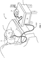
- a system 10 includes an oral device 12 (shown in broken line in the oral cavity of a patient P), a control enclosure 14 which is suitable for placement on the top of the table T, and a connector line assembly usually including first and second tubular connectors 18 and 20, better illustrated in Fig. 2-6 .
- the oral device 12 includes an internal plenum 22 which extends from an inlet 24 to an outlet 26.
- the plenum 22 is typically integrally formed within the oral device 12, usually being formed as part of a molding process. Alternatively, the plenum 22 could be formed separately and attached to a separate body of the device.
- the oral device will include one or more vacuum ports 27, where the inlet s are typically formed on an anterior end of the device which will be held near the patient's lips in the oral cavity while the vacuums 27 are on the posterior end of the device which will be near the patient's soft palate when the device is in the patient's oral cavity.
- a vacuum is drawn in the plenum 22 by vacuum pump 28 which is connected to the outlet 26 by tubular connector 20.
- an air source 30 is placed in front of the inlet 24, typically being connected by tubular connector 18.
- the vacuum pump 28 will typically be a diaphragm or other positive displacement pump where the pump speed may be varied in order to control the volume and/or pressure of air pulled from the device 12.
- the delivery capacity of the air source 30 may be selected and/or controlled.
- the air source 30 will comprise a flow restrictor having a fixed orifice, more usually having an orifice area in the range from 0.01 mm 2 to 0.025 mm 2 .
- the air source 30 could comprise an adjustable orifice valve or a pump which is operated to deliver a fixed volume of air bleed into the plenum 22.
- the controller could automatically control either the valve or the positive pressure pump to help maintain the target vacuum within the plenum of the oral device.
- a saliva or moisture trap 32 will be placed in the flow path from the outlet 26 of the oral device 12 to the vacuum pump 28 in order to receive most or all of the air flow from the oral device and to remove saliva and moisture from the air flow before entering the vacuum pump.
- the trap 32 will be placed close to the inlet to the vacuum pump although it could be elsewhere in the system.
- At least one pressure and/or flow sensor 40 will be provided in the air bleed inlet flow path between the air source 30 and the inlet 24, or optionally though less desirably within the plenum 22 of the device itself.
- the pressure/flow sensor 40 will detect the pressure/flow within the plenum either directly or indirectly, allowing controller 34 to control either the vacuum pump 28 and/or the air source 30 in order to maintain a target vacuum within the plenum, typically in the range from 20 mmHg to 75 mmHg, preferably in the range from 30 mmHg to 55 mmHg.
- a second pressure and/or flow sensor 42 may be provided between the outlet 26 of the oral device 12 and the vacuum pump 28, typically between the saliva trap 32 and the vacuum pump 28.
- the pressure and/or flow measured by sensor 42 can be compared with the reading from sensor 40 to make sure that the flow and/or pressure within the plenum 22 of the oral device 12 are within proper operating ranges. For example, should saliva or any other material or failure block flow within the plenum 22, the readings between the sensor 40 and sensor 42 would be expected to deviate substantially, indicating a system failure.
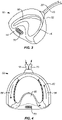
- the oral device is fabricated from a polymer such as a polycarbonate or a polyvinyl acetate polymer (e.g., Versaflex ® polymer), which may be molded or otherwise formed to have an anterior end 52 and a cross-member 54 at a posterior end.
- Bite plates 56 are formed on each side of the oral device 50, and the cross-member 54 includes a plurality of vacuum ports 58 formed on an upwardly and forwardly inclined surface 60 of the cross-member 54.
- Plenum 62 is formed in the interior of the oral device 50 and provides a circulation path shown by the arrows in Fig. 4 . While the oral device 50 is exemplary of those useful in the systems and methods of the present disclosure, many other devices having the vacuum plenum, inlet and outlet, and vacuum ports would also be useful.
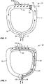
- an oral appliance 70 comprises a first bite structure or leg 74 and a second bite structure or leg 76.
- the first and second bite structures are joined at a posterior end by a cross-member 79 having a plurality of vacuum ports 84 formed over a posterior surface thereof.
- An air bleed as generally described above, enters an interior passage or a lumen within the first bite structure 74 through an inlet 78. Instead of circulating through a continuous plenum to outlet 80, as with previous embodiments, the air entering through inlet 78 will pass into the patient's oral cavity through a bypass outlet 82.
- That air, or at least an equivalent volume or mass of air, will pass back into the plenum through the vacuum ports 84 together with any additional air which may have leaked into the patient's oral cavity which needs to be removed.
- the combined air streams will then flow down through the second bite structure or leg 76 and out the outlet 80, to the vacuum control system as described previously for other embodiments.
- a barrier 86 will usually be disposed in the plenum between the bypass port 80 and the vacuum ports 84.
- an oral appliance 90 incorporating still alternative features includes a first bite structure or leg 92 and a second bite structure or leg 94.
- the first bite structure 92 has an interior passage or lumen which is divided into inlet and outlet segments by a barrier or wall 100.
- a plenum inlet 98 is located at the anterior end of a first of the divided passages so that air bleed entering the inlet can flow in a posterior direction until it reaches cross-member 95 disposed between the bite structures 92 and 94.
- a wall or partition 100 terminates at that point so the air inflow can turn to pass in the opposite direction through the second portion of the divided air plenum so that a continuous air bleed is constantly maintained by vacuum port(s) 102 located on a posterior surface of the cross-member.
- the combined flows of the air bleed and any air which is drawn in through the vacuum port(s) then extends in an anterior direction through the other segment of the passage within the first bite structure so that it can exit through outlet 96.
- the interior of the second bite structure or leg 94 will be blocked and isolated from the air flow so that it does not become contaminated.
Landscapes
- Health & Medical Sciences (AREA)
- Heart & Thoracic Surgery (AREA)
- Life Sciences & Earth Sciences (AREA)
- Veterinary Medicine (AREA)
- Public Health (AREA)
- General Health & Medical Sciences (AREA)
- Animal Behavior & Ethology (AREA)
- Biomedical Technology (AREA)
- Engineering & Computer Science (AREA)
- Pulmonology (AREA)
- Anesthesiology (AREA)
- Hematology (AREA)
- Vascular Medicine (AREA)
- Otolaryngology (AREA)
- Emergency Medicine (AREA)
- Nursing (AREA)
- Orthopedic Medicine & Surgery (AREA)
- Dentistry (AREA)
- Epidemiology (AREA)
- Orthopedics, Nursing, And Contraception (AREA)
- Dental Tools And Instruments Or Auxiliary Dental Instruments (AREA)
- Investigating Or Analysing Biological Materials (AREA)
- Measuring And Recording Apparatus For Diagnosis (AREA)
Applications Claiming Priority (2)
| Application Number | Priority Date | Filing Date | Title |
|---|---|---|---|
| US13/023,763 US8979823B2 (en) | 2011-02-09 | 2011-02-09 | Saliva management system with continuous flow through oral device |
| PCT/US2012/024030 WO2012109166A2 (en) | 2011-02-09 | 2012-02-06 | Saliva management system with continuous flow through oral device |
Publications (3)
| Publication Number | Publication Date |
|---|---|
| EP2672939A2 EP2672939A2 (en) | 2013-12-18 |
| EP2672939A4 EP2672939A4 (en) | 2017-12-06 |
| EP2672939B1 true EP2672939B1 (en) | 2022-06-01 |
Family
ID=46599813
Family Applications (1)
| Application Number | Title | Priority Date | Filing Date |
|---|---|---|---|
| EP12744218.4A Active EP2672939B1 (en) | 2011-02-09 | 2012-02-06 | Saliva management system with continuous flow through oral device |
Country Status (6)
| Country | Link |
|---|---|
| US (3) | US8979823B2 (enExample) |
| EP (1) | EP2672939B1 (enExample) |
| JP (2) | JP5944928B2 (enExample) |
| CN (1) | CN103717181B (enExample) |
| ES (1) | ES2918599T3 (enExample) |
| WO (1) | WO2012109166A2 (enExample) |
Families Citing this family (32)
| Publication number | Priority date | Publication date | Assignee | Title |
|---|---|---|---|---|
| US8505540B2 (en) | 2007-11-13 | 2013-08-13 | Apnicure, Inc. | Methods and systems for improving airway patency |
| US8122889B2 (en) | 2007-11-13 | 2012-02-28 | Apnicure, Inc. | Methods and systems for improving airway patency |
| US8979823B2 (en) | 2011-02-09 | 2015-03-17 | Apnicure, Inc. | Saliva management system with continuous flow through oral device |
| US9414899B2 (en) * | 2011-07-28 | 2016-08-16 | Jennifer Rebecca Altounian | System and method for saliva replenishment and control |
| US11185399B2 (en) | 2012-02-06 | 2021-11-30 | Nuflow Inc. | Flexible surgical suction device and method |
| US20130203012A1 (en) * | 2012-02-06 | 2013-08-08 | Anthony Walker | Flexible Surgical Suction Device and Method |
| US9375541B2 (en) | 2012-07-11 | 2016-06-28 | Apnicure, Inc. | Apparatus and methods for reducing foaming during saliva collection |
| US8387620B1 (en) | 2012-08-23 | 2013-03-05 | Apnicure, Inc. | Oral device for anterior advancement and medial constraint of the tongue |
| US9387119B2 (en) | 2012-08-23 | 2016-07-12 | Apnicure, Inc. | Oral device for anterior advancement of the tongue |
| US20140360509A1 (en) * | 2013-06-06 | 2014-12-11 | Apnicure, Inc. | Heating Element for Reducing Foaming During Saliva Collection |
| WO2016138667A1 (zh) * | 2015-03-05 | 2016-09-09 | 莱镁医疗器材股份有限公司 | 提高上呼吸道通畅度的系统及其方法 |
| TWI577403B (zh) * | 2015-04-01 | 2017-04-11 | 晶湛生技有限公司 | 口呼吸器 |
| US9788922B2 (en) * | 2015-04-08 | 2017-10-17 | Bennett H. Jacoby | Systems and methods for removal of dental biofilm using irrigation |
| US10166140B2 (en) | 2015-06-25 | 2019-01-01 | Somnics, Inc. | Liquid container and absorbent insert for oral negative-pressure therapy system |
| US10543331B2 (en) * | 2015-12-01 | 2020-01-28 | Cook Medical Technologies Llc | Fluid delivery system to airway |
| US20170216148A1 (en) * | 2015-12-09 | 2017-08-03 | Jennifer Rebecca Altounian | System and method for saliva replenishment and control |
| US11744933B2 (en) | 2015-12-09 | 2023-09-05 | Saliva Management Systems, Inc. | Saliva management system |
| CN105832438B (zh) * | 2016-06-15 | 2019-02-01 | 北京大学第三医院 | 临床用唾液汲取装置 |
| US10251734B1 (en) | 2017-07-11 | 2019-04-09 | Douglas McLaughlin | Saliva management system |
| CN107822727A (zh) * | 2017-12-12 | 2018-03-23 | 宁波江北怡和工业设计有限公司 | 一种老年人吞咽功能缓解装置 |
| CN107822728A (zh) * | 2017-12-12 | 2018-03-23 | 宁波江北怡和工业设计有限公司 | 老年人自动吸口水装置 |
| CN108542563B (zh) * | 2018-06-07 | 2023-11-21 | 四川大学华西医院 | 医用口腔湿化吸干器 |
| TWI684447B (zh) * | 2018-06-27 | 2020-02-11 | 亞東技術學院 | 穿戴式流涎監測裝置及流涎監測方法 |
| US20200405988A1 (en) * | 2019-06-28 | 2020-12-31 | Derrick Flint | Oral care device for intubation |
| WO2021232701A1 (zh) | 2020-05-21 | 2021-11-25 | 佳音医疗器材股份有限公司 | 用于改善睡眠呼吸阻塞的装置 |
| US20230248566A1 (en) * | 2020-06-18 | 2023-08-10 | Jose Venegas | Oral appliance and method for treating sleep disorders |
| US11571285B2 (en) * | 2020-09-09 | 2023-02-07 | Loma Linda University | Evacuation dam frame |
| US20220370748A1 (en) * | 2020-09-16 | 2022-11-24 | POM Medical, LLC | Passive oxygen mask vacuum regulation system |
| CN112914750B (zh) * | 2021-03-08 | 2022-01-18 | 吉林大学第一医院 | 一种癫痫患者用辅助口部防护装置 |
| USD1079013S1 (en) | 2021-10-20 | 2025-06-10 | Swiftsure Innovations Inc. | Oral irrigation device |
| USD1084352S1 (en) | 2022-01-21 | 2025-07-15 | Swiftsure Innovations Inc. | Oral irrigation device |
| USD1088237S1 (en) | 2022-01-21 | 2025-08-12 | Swiftsure Innovations Inc. | Oral irrigation device |
Family Cites Families (87)
| Publication number | Priority date | Publication date | Assignee | Title |
|---|---|---|---|---|
| US1012613A (en) | 1911-03-04 | 1911-12-26 | William P De Witt | Saliva-ejector. |
| US2560915A (en) * | 1947-04-05 | 1951-07-17 | Alfred A Bamberger | Sump drain |
| US3132647A (en) | 1962-04-19 | 1964-05-12 | Corniello Giuseppe | Anti-snoring device |
| US3489141A (en) * | 1966-12-29 | 1970-01-13 | Lamar G Warren Jr | Dental treatment device |
| US3566869A (en) * | 1968-12-26 | 1971-03-02 | David Lamar Crowson | Vacuum-utilizing hygienic teeth-cleaning system |
| US3731675A (en) * | 1971-05-03 | 1973-05-08 | J Kelly | Dental cleaning apparatus |
| US3952743A (en) * | 1973-03-28 | 1976-04-27 | Unisearch Limited | Suction device |
| US4053984A (en) * | 1976-08-05 | 1977-10-18 | Moss Dan E | Mouth prop |
| US4164940A (en) * | 1977-12-30 | 1979-08-21 | Quinby James D | Dental cleaning and massaging apparatus |
| US4169473A (en) | 1978-03-03 | 1979-10-02 | Samelson Charles F | Anti-snoring and anti-bruxism device |
| US4304227A (en) | 1978-03-03 | 1981-12-08 | Samelson Charles F | Device for treatment of snoring, bruxism or for avoidance of sleep apnea |
| US4735606A (en) * | 1982-10-12 | 1988-04-05 | Sherwood Medical Company | Chest drainage apparatus |
| US4676240A (en) | 1985-09-09 | 1987-06-30 | Gardy Victor R | Tongue locking device to minimize effects of sleep apnea and to reduce snoring |
| US4669459A (en) | 1985-11-29 | 1987-06-02 | Spiewak Martin H | Anti-snoring device |
| ES2019457B3 (es) * | 1987-06-22 | 1991-06-16 | Takeda Chemical Industries Ltd | Equipo de succion para operacion medica. |
| US4802851A (en) | 1988-02-03 | 1989-02-07 | Rhoades Clark J | Dental appliance |
| US5127411A (en) | 1988-10-12 | 1992-07-07 | Arnold Schoolman | Oral appliance for removing aerosols produced during dentistry |
| US5062413A (en) * | 1989-06-06 | 1991-11-05 | Horace Bullard | Vacuum teeth cleaning system |
| US5050616A (en) | 1990-03-14 | 1991-09-24 | The United States Of America As Represented By The Secretary Of The Department Of Health And Human Services | Universal collector for submandibular-sublingual saliva |
| US5104315A (en) | 1990-04-11 | 1992-04-14 | Mckinley Earl O | Oral hygiene device |
| US5018967A (en) * | 1990-08-15 | 1991-05-28 | Stephen Schwalbach | Dental fluoride applicator and method for using same |
| FI92286C (fi) * | 1992-02-21 | 1994-10-25 | Instrumentarium Oy | Laitteisto potilaalle hengitysjakson aikana toimitetun kaasutilavuuden säätämiseksi |
| DE4306478A1 (de) * | 1993-03-02 | 1994-09-08 | Wolfgang Dr Wagner | Drainagevorrichtung, insbesondere Pleuradrainagevorrichtung, und Drainageverfahren |
| US5494441A (en) * | 1993-08-02 | 1996-02-27 | Nicholson; James A. | Oral therapeutic apparatus and method of treating oral tissue during chemotherapy |
| US5513986A (en) | 1993-10-21 | 1996-05-07 | Erika B. Feltham | Intraoral dental apparatus |
| US5465734A (en) | 1994-01-12 | 1995-11-14 | Snorex, Inc. | Adjustable tongue positioning device and method |
| US5503629A (en) * | 1994-05-20 | 1996-04-02 | Catone; Guy A. | System for enhancing nourishment of a maxillomandibularly fixated patient |
| AUPN304895A0 (en) | 1995-05-19 | 1995-06-15 | Somed Pty Limited | Device for detecting and recording snoring |
| US5588836A (en) | 1995-10-23 | 1996-12-31 | Op-D-Op, Inc. | Mouth prop and tongue deflector apparatus |
| JPH09201233A (ja) * | 1996-01-24 | 1997-08-05 | Natl Dentaru Lab:Kk | 給排水機能を備えた歯ブラシ |
| US5971977A (en) * | 1996-07-22 | 1999-10-26 | Korenfeld; Michael S. | Surgical laser smoke plume evacuator |
| WO1998038944A1 (en) * | 1997-03-05 | 1998-09-11 | Board Of Regents, The University Of Texas System | Self-sealed irrigation system |
| US5915385A (en) | 1997-04-02 | 1999-06-29 | Hakimi; Farhad | Snore and stress relieving device |
| US20100113956A1 (en) * | 1997-04-29 | 2010-05-06 | Salter Labs | Nasal cannula for acquiring breathing information |
| US5957133A (en) | 1997-07-21 | 1999-09-28 | Hart; William T. | Oral appliance with negative air supply for reducing sleep apnea and snoring |
| US5873718A (en) * | 1998-05-19 | 1999-02-23 | Sullivan; Terence C. | Dental apparatus to remove saliva while retracting cheeks, lips and tongue |
| US6458109B1 (en) * | 1998-08-07 | 2002-10-01 | Hill-Rom Services, Inc. | Wound treatment apparatus |
| US6820617B2 (en) | 1998-08-13 | 2004-11-23 | Fisher & Paykel Limited | Breathing assistance apparatus |
| US6679257B1 (en) | 1998-08-13 | 2004-01-20 | Fisher & Paykel Limited | Breathing assistance apparatus |
| JP4294902B2 (ja) | 1999-12-15 | 2009-07-15 | イノヴェーティヴ ヘルス テクノロジーズ(ニュージーランド) リミテッド | 舌安定化器具 |
| US6877513B2 (en) | 2000-01-21 | 2005-04-12 | Respironics, Inc. | Intraoral apparatus for enhancing airway patency |
| US6454724B1 (en) | 2000-10-25 | 2002-09-24 | Safe Flight Instrument Corporation | Sleep apnea detection system and method |
| NZ526395A (en) | 2000-12-11 | 2005-11-25 | Resmed Ltd | Methods and apparatus for stroke patient treatment |
| SE0100066D0 (sv) * | 2001-01-10 | 2001-01-10 | Siemens Elema Ab | Handventilationsblåsa |
| US6494209B2 (en) | 2001-04-02 | 2002-12-17 | George Kulick | Method and apparatus for treatment of snoring, hypopnea and apnea |
| US6675802B1 (en) | 2001-05-08 | 2004-01-13 | W. Keith Thornton | Device for improving breathing incorporating a detachable venting seal |
| DE20111396U1 (de) | 2001-07-12 | 2001-10-18 | Hoffrichter Medizintechnik GmbH, 19061 Schwerin | Atemtherapiegerät |
| US20030204213A1 (en) | 2002-04-30 | 2003-10-30 | Jensen Donald N. | Method and apparatus to detect and monitor the frequency of obstructive sleep apnea |
| US7073505B2 (en) | 2002-09-06 | 2006-07-11 | Apneon, Inc. | Systems and methods for moving and/or restraining tissue in the oral cavity |
| US6955172B2 (en) | 2002-09-06 | 2005-10-18 | Apneon, Inc. | Systems and methods for moving and/or restraining the tongue in the oral cavity |
| CA2497805A1 (en) | 2002-09-06 | 2004-03-18 | Apneon, Inc. | Systems and methods for moving and/or restraining tissue in the upper respiratory system |
| US20040194787A1 (en) | 2003-04-01 | 2004-10-07 | Miller Chipp St. Kevin | Anti-snoring device and method of use |
| JP4245439B2 (ja) * | 2003-08-08 | 2009-03-25 | 三洋電機株式会社 | いびき防止装置 |
| JP3871666B2 (ja) * | 2003-08-13 | 2007-01-24 | 吉登 井上 | 歯科用器具及び歯科用器具の製造方法 |
| US6976491B2 (en) | 2003-10-30 | 2005-12-20 | D Agosto Joseph | Gag-less airway for snoring prevention |
| US20050166928A1 (en) | 2004-01-30 | 2005-08-04 | Yandong Jiang | Methods and devices for maintaining an open airway |
| US8091554B2 (en) | 2004-01-30 | 2012-01-10 | The General Hospital Corporation | Methods and devices for relieving upper airway obstructions |
| JP2007520279A (ja) | 2004-01-30 | 2007-07-26 | ザ・ジエネラル・ホスピタル・コーポレーシヨン・ドウーイング・ビジネス・アズ・マサチユセツツ・ジエネラル・ホスピタル | 上部気道の閉塞を改善するための方法と装置 |
| US8074655B2 (en) | 2004-02-26 | 2011-12-13 | Linguaflex, Inc. | Methods and devices for treating sleep apnea and snoring |
| AU2005216988B2 (en) | 2004-02-26 | 2011-01-20 | Linguaflex, Inc. | A method and device for the treatment of obstructive sleep apnea and snoring |
| US6893259B1 (en) * | 2004-03-08 | 2005-05-17 | Igor Reizenson | Oral hygiene device and method of use therefor |
| DE102004014841B4 (de) | 2004-03-24 | 2006-07-06 | Schwarz Pharma Ag | Verwendung von Rotigotin zur Behandlung und Prävention des Parkinson-Plus-Syndroms |
| US20050236003A1 (en) | 2004-04-16 | 2005-10-27 | Meader Charles R | Apnea nipple and oral airway and mandibular advancement device |
| SE529989C2 (sv) * | 2004-09-03 | 2008-01-29 | Ric Investments Llc | Gasregulator |
| DE102004049950A1 (de) * | 2004-10-13 | 2006-05-04 | Johnki, Bernd J., Dr.med.dent. | Vorrichtung zur Reinigung und/oder Pflege von Zähnen und/oder Zahnfleisch |
| US7798146B2 (en) | 2004-10-29 | 2010-09-21 | Ric Investments, Llc | Oral appliance |
| SE528487C2 (sv) * | 2004-11-11 | 2006-11-28 | Transunit Ab | Exspiratorisk tryckregulator |
| WO2006063403A1 (en) | 2004-12-15 | 2006-06-22 | John Razmovski | Oral cavity manipulator |
| WO2006102708A1 (en) | 2005-04-01 | 2006-10-05 | Resmed Limited | Mask pressure regulation in cpap treatment and assisted respiration by dynamic control of mask vent flow |
| CA2966418A1 (en) | 2005-05-03 | 2006-11-09 | The University Of Western Ontario | An oral device and kit for use in association therewith |
| US7861722B2 (en) | 2005-06-23 | 2011-01-04 | Bryan Keropian | Sleep appliance |
| WO2007013049A1 (en) * | 2005-07-24 | 2007-02-01 | Carmeli Adahan | Wound closure and drainage system |
| US7503910B2 (en) | 2006-02-01 | 2009-03-17 | Carmeli Adahan | Suctioning system, method and kit |
| WO2007013064A1 (en) * | 2005-07-24 | 2007-02-01 | Carmeli Adahan | Suctioning system, method and kit |
| GR20050100452A (el) * | 2005-09-02 | 2007-04-25 | Estelle Enterprises Limited | Συστημα καθετηρα ανταλλαγης υγρων |
| US20080308112A1 (en) | 2005-12-20 | 2008-12-18 | Koninklijke Philips Electronics, N.V. | System and Method for Reducing Snoring and/or Sleep Apnea of Sleeping Person |
| US7918222B2 (en) | 2006-05-30 | 2011-04-05 | Industrial Technology Research Institute | Method and apparatus for treating obstructive sleep apnea by using negative oral pressure to a patient |
| US8857439B2 (en) * | 2006-06-19 | 2014-10-14 | Insono Therapeutics, Inc. | Variable automated tissue retention system |
| EP2481434B1 (en) * | 2006-12-15 | 2016-04-13 | ResMed Ltd. | Delivery of respiratory therapy |
| US8573223B2 (en) | 2010-07-20 | 2013-11-05 | Apnicure, Inc. | Airway device with tongue-engaging member |
| US8505540B2 (en) | 2007-11-13 | 2013-08-13 | Apnicure, Inc. | Methods and systems for improving airway patency |
| US8122889B2 (en) | 2007-11-13 | 2012-02-28 | Apnicure, Inc. | Methods and systems for improving airway patency |
| US20090208898A1 (en) * | 2008-02-15 | 2009-08-20 | Glen Kaplan | Fluid jet bristle aggitation toothbrush fixture |
| CN102143771B (zh) * | 2008-09-18 | 2014-03-12 | 凯希特许有限公司 | 用于将减压传送到皮下组织的系统和方法 |
| US9022959B2 (en) * | 2009-07-30 | 2015-05-05 | Mcneil-Ppc, Inc. | Oral care systems |
| US20120219926A1 (en) * | 2010-06-18 | 2012-08-30 | S2L, Llc | Cleaning Device for Teeth and Mouth, and Cleaning Methods |
| US8979823B2 (en) | 2011-02-09 | 2015-03-17 | Apnicure, Inc. | Saliva management system with continuous flow through oral device |
-
2011
- 2011-02-09 US US13/023,763 patent/US8979823B2/en active Active
-
2012
- 2012-02-06 ES ES12744218T patent/ES2918599T3/es active Active
- 2012-02-06 JP JP2013553481A patent/JP5944928B2/ja active Active
- 2012-02-06 CN CN201280017595.0A patent/CN103717181B/zh active Active
- 2012-02-06 EP EP12744218.4A patent/EP2672939B1/en active Active
- 2012-02-06 WO PCT/US2012/024030 patent/WO2012109166A2/en not_active Ceased
-
2015
- 2015-02-17 US US14/624,088 patent/US9549795B2/en active Active
-
2016
- 2016-05-26 JP JP2016105140A patent/JP2016147190A/ja not_active Ceased
- 2016-12-12 US US15/376,368 patent/US10245175B2/en active Active
Also Published As
| Publication number | Publication date |
|---|---|
| CN103717181A (zh) | 2014-04-09 |
| JP2016147190A (ja) | 2016-08-18 |
| JP2014512200A (ja) | 2014-05-22 |
| EP2672939A4 (en) | 2017-12-06 |
| US9549795B2 (en) | 2017-01-24 |
| WO2012109166A2 (en) | 2012-08-16 |
| US20150157433A1 (en) | 2015-06-11 |
| EP2672939A2 (en) | 2013-12-18 |
| JP5944928B2 (ja) | 2016-07-05 |
| WO2012109166A3 (en) | 2014-02-20 |
| CN103717181B (zh) | 2016-08-17 |
| US20120199135A1 (en) | 2012-08-09 |
| US8979823B2 (en) | 2015-03-17 |
| US10245175B2 (en) | 2019-04-02 |
| ES2918599T3 (es) | 2022-07-19 |
| US20170087004A1 (en) | 2017-03-30 |
Similar Documents
| Publication | Publication Date | Title |
|---|---|---|
| EP2672939B1 (en) | Saliva management system with continuous flow through oral device | |
| CN103140192B (zh) | 具有舌接合构件的气道设备 | |
| US9610190B2 (en) | Methods and systems for improving airway patency | |
| JP5404642B2 (ja) | 気道開存性を改善する方法およびシステム | |
| US8387620B1 (en) | Oral device for anterior advancement and medial constraint of the tongue | |
| US8667970B2 (en) | Airway device with tongue-engaging member | |
| JP2014512200A5 (enExample) | ||
| WO2005016402A2 (en) | Nasal ventilation interface and system | |
| US20160270949A1 (en) | Oral device for anterior advancement of the tongue | |
| WO2016165103A1 (zh) | 口部介面装置的唾液处理系统及其方法 | |
| CN202236817U (zh) | 单头可调防吸壁胃肠减压管 | |
| WO2014117164A2 (en) | Airway device with tongue-engaging member | |
| TW201637677A (zh) | 口部介面裝置之唾液處理系統及其方法 | |
| CN104758989A (zh) | 双管牙垫防护式高频喷射氧气吸痰导流器 |
Legal Events
| Date | Code | Title | Description |
|---|---|---|---|
| PUAI | Public reference made under article 153(3) epc to a published international application that has entered the european phase |
Free format text: ORIGINAL CODE: 0009012 |
|
| 17P | Request for examination filed |
Effective date: 20130903 |
|
| AK | Designated contracting states |
Kind code of ref document: A2 Designated state(s): AL AT BE BG CH CY CZ DE DK EE ES FI FR GB GR HR HU IE IS IT LI LT LU LV MC MK MT NL NO PL PT RO RS SE SI SK SM TR |
|
| R17D | Deferred search report published (corrected) |
Effective date: 20140220 |
|
| RIC1 | Information provided on ipc code assigned before grant |
Ipc: A61F 5/56 20060101AFI20171026BHEP |
|
| A4 | Supplementary search report drawn up and despatched |
Effective date: 20171107 |
|
| STAA | Information on the status of an ep patent application or granted ep patent |
Free format text: STATUS: REQUEST FOR EXAMINATION WAS MADE |
|
| STAA | Information on the status of an ep patent application or granted ep patent |
Free format text: STATUS: EXAMINATION IS IN PROGRESS |
|
| 17Q | First examination report despatched |
Effective date: 20200804 |
|
| GRAP | Despatch of communication of intention to grant a patent |
Free format text: ORIGINAL CODE: EPIDOSNIGR1 |
|
| STAA | Information on the status of an ep patent application or granted ep patent |
Free format text: STATUS: GRANT OF PATENT IS INTENDED |
|
| INTG | Intention to grant announced |
Effective date: 20211221 |
|
| GRAS | Grant fee paid |
Free format text: ORIGINAL CODE: EPIDOSNIGR3 |
|
| GRAA | (expected) grant |
Free format text: ORIGINAL CODE: 0009210 |
|
| STAA | Information on the status of an ep patent application or granted ep patent |
Free format text: STATUS: THE PATENT HAS BEEN GRANTED |
|
| AK | Designated contracting states |
Kind code of ref document: B1 Designated state(s): AL AT BE BG CH CY CZ DE DK EE ES FI FR GB GR HR HU IE IS IT LI LT LU LV MC MK MT NL NO PL PT RO RS SE SI SK SM TR |
|
| REG | Reference to a national code |
Ref country code: GB Ref legal event code: FG4D |
|
| REG | Reference to a national code |
Ref country code: AT Ref legal event code: REF Ref document number: 1494892 Country of ref document: AT Kind code of ref document: T Effective date: 20220615 Ref country code: CH Ref legal event code: EP Ref country code: DE Ref legal event code: R096 Ref document number: 602012078295 Country of ref document: DE |
|
| REG | Reference to a national code |
Ref country code: IE Ref legal event code: FG4D |
|
| REG | Reference to a national code |
Ref country code: ES Ref legal event code: FG2A Ref document number: 2918599 Country of ref document: ES Kind code of ref document: T3 Effective date: 20220719 |
|
| REG | Reference to a national code |
Ref country code: LT Ref legal event code: MG9D |
|
| REG | Reference to a national code |
Ref country code: NL Ref legal event code: MP Effective date: 20220601 |
|
| REG | Reference to a national code |
Ref country code: DE Ref legal event code: R081 Ref document number: 602012078295 Country of ref document: DE Owner name: SOMNICS, INC., ZHUBEI, TW Free format text: FORMER OWNER: APNICURE, INC., REDWOOD CITY, CA, US |
|
| PG25 | Lapsed in a contracting state [announced via postgrant information from national office to epo] |
Ref country code: SE Free format text: LAPSE BECAUSE OF FAILURE TO SUBMIT A TRANSLATION OF THE DESCRIPTION OR TO PAY THE FEE WITHIN THE PRESCRIBED TIME-LIMIT Effective date: 20220601 Ref country code: NO Free format text: LAPSE BECAUSE OF FAILURE TO SUBMIT A TRANSLATION OF THE DESCRIPTION OR TO PAY THE FEE WITHIN THE PRESCRIBED TIME-LIMIT Effective date: 20220901 Ref country code: LT Free format text: LAPSE BECAUSE OF FAILURE TO SUBMIT A TRANSLATION OF THE DESCRIPTION OR TO PAY THE FEE WITHIN THE PRESCRIBED TIME-LIMIT Effective date: 20220601 Ref country code: HR Free format text: LAPSE BECAUSE OF FAILURE TO SUBMIT A TRANSLATION OF THE DESCRIPTION OR TO PAY THE FEE WITHIN THE PRESCRIBED TIME-LIMIT Effective date: 20220601 Ref country code: GR Free format text: LAPSE BECAUSE OF FAILURE TO SUBMIT A TRANSLATION OF THE DESCRIPTION OR TO PAY THE FEE WITHIN THE PRESCRIBED TIME-LIMIT Effective date: 20220902 Ref country code: FI Free format text: LAPSE BECAUSE OF FAILURE TO SUBMIT A TRANSLATION OF THE DESCRIPTION OR TO PAY THE FEE WITHIN THE PRESCRIBED TIME-LIMIT Effective date: 20220601 Ref country code: BG Free format text: LAPSE BECAUSE OF FAILURE TO SUBMIT A TRANSLATION OF THE DESCRIPTION OR TO PAY THE FEE WITHIN THE PRESCRIBED TIME-LIMIT Effective date: 20220901 |
|
| RAP2 | Party data changed (patent owner data changed or rights of a patent transferred) |
Owner name: SOMNICS, INC. |
|
| REG | Reference to a national code |
Ref country code: GB Ref legal event code: 732E Free format text: REGISTERED BETWEEN 20221013 AND 20221019 |
|
| REG | Reference to a national code |
Ref country code: AT Ref legal event code: MK05 Ref document number: 1494892 Country of ref document: AT Kind code of ref document: T Effective date: 20220601 |
|
| PG25 | Lapsed in a contracting state [announced via postgrant information from national office to epo] |
Ref country code: RS Free format text: LAPSE BECAUSE OF FAILURE TO SUBMIT A TRANSLATION OF THE DESCRIPTION OR TO PAY THE FEE WITHIN THE PRESCRIBED TIME-LIMIT Effective date: 20220601 Ref country code: PL Free format text: LAPSE BECAUSE OF FAILURE TO SUBMIT A TRANSLATION OF THE DESCRIPTION OR TO PAY THE FEE WITHIN THE PRESCRIBED TIME-LIMIT Effective date: 20220601 Ref country code: LV Free format text: LAPSE BECAUSE OF FAILURE TO SUBMIT A TRANSLATION OF THE DESCRIPTION OR TO PAY THE FEE WITHIN THE PRESCRIBED TIME-LIMIT Effective date: 20220601 |
|
| PG25 | Lapsed in a contracting state [announced via postgrant information from national office to epo] |
Ref country code: NL Free format text: LAPSE BECAUSE OF FAILURE TO SUBMIT A TRANSLATION OF THE DESCRIPTION OR TO PAY THE FEE WITHIN THE PRESCRIBED TIME-LIMIT Effective date: 20220601 |
|
| PG25 | Lapsed in a contracting state [announced via postgrant information from national office to epo] |
Ref country code: SM Free format text: LAPSE BECAUSE OF FAILURE TO SUBMIT A TRANSLATION OF THE DESCRIPTION OR TO PAY THE FEE WITHIN THE PRESCRIBED TIME-LIMIT Effective date: 20220601 Ref country code: SK Free format text: LAPSE BECAUSE OF FAILURE TO SUBMIT A TRANSLATION OF THE DESCRIPTION OR TO PAY THE FEE WITHIN THE PRESCRIBED TIME-LIMIT Effective date: 20220601 Ref country code: RO Free format text: LAPSE BECAUSE OF FAILURE TO SUBMIT A TRANSLATION OF THE DESCRIPTION OR TO PAY THE FEE WITHIN THE PRESCRIBED TIME-LIMIT Effective date: 20220601 Ref country code: PT Free format text: LAPSE BECAUSE OF FAILURE TO SUBMIT A TRANSLATION OF THE DESCRIPTION OR TO PAY THE FEE WITHIN THE PRESCRIBED TIME-LIMIT Effective date: 20221003 Ref country code: EE Free format text: LAPSE BECAUSE OF FAILURE TO SUBMIT A TRANSLATION OF THE DESCRIPTION OR TO PAY THE FEE WITHIN THE PRESCRIBED TIME-LIMIT Effective date: 20220601 Ref country code: CZ Free format text: LAPSE BECAUSE OF FAILURE TO SUBMIT A TRANSLATION OF THE DESCRIPTION OR TO PAY THE FEE WITHIN THE PRESCRIBED TIME-LIMIT Effective date: 20220601 Ref country code: AT Free format text: LAPSE BECAUSE OF FAILURE TO SUBMIT A TRANSLATION OF THE DESCRIPTION OR TO PAY THE FEE WITHIN THE PRESCRIBED TIME-LIMIT Effective date: 20220601 |
|
| REG | Reference to a national code |
Ref country code: FR Ref legal event code: PLFP Year of fee payment: 12 |
|
| PG25 | Lapsed in a contracting state [announced via postgrant information from national office to epo] |
Ref country code: IS Free format text: LAPSE BECAUSE OF FAILURE TO SUBMIT A TRANSLATION OF THE DESCRIPTION OR TO PAY THE FEE WITHIN THE PRESCRIBED TIME-LIMIT Effective date: 20221001 |
|
| REG | Reference to a national code |
Ref country code: DE Ref legal event code: R097 Ref document number: 602012078295 Country of ref document: DE |
|
| PG25 | Lapsed in a contracting state [announced via postgrant information from national office to epo] |
Ref country code: AL Free format text: LAPSE BECAUSE OF FAILURE TO SUBMIT A TRANSLATION OF THE DESCRIPTION OR TO PAY THE FEE WITHIN THE PRESCRIBED TIME-LIMIT Effective date: 20220601 |
|
| PLBE | No opposition filed within time limit |
Free format text: ORIGINAL CODE: 0009261 |
|
| STAA | Information on the status of an ep patent application or granted ep patent |
Free format text: STATUS: NO OPPOSITION FILED WITHIN TIME LIMIT |
|
| PG25 | Lapsed in a contracting state [announced via postgrant information from national office to epo] |
Ref country code: DK Free format text: LAPSE BECAUSE OF FAILURE TO SUBMIT A TRANSLATION OF THE DESCRIPTION OR TO PAY THE FEE WITHIN THE PRESCRIBED TIME-LIMIT Effective date: 20220601 |
|
| 26N | No opposition filed |
Effective date: 20230302 |
|
| PG25 | Lapsed in a contracting state [announced via postgrant information from national office to epo] |
Ref country code: SI Free format text: LAPSE BECAUSE OF FAILURE TO SUBMIT A TRANSLATION OF THE DESCRIPTION OR TO PAY THE FEE WITHIN THE PRESCRIBED TIME-LIMIT Effective date: 20220601 |
|
| P01 | Opt-out of the competence of the unified patent court (upc) registered |
Effective date: 20230517 |
|
| PG25 | Lapsed in a contracting state [announced via postgrant information from national office to epo] |
Ref country code: MC Free format text: LAPSE BECAUSE OF FAILURE TO SUBMIT A TRANSLATION OF THE DESCRIPTION OR TO PAY THE FEE WITHIN THE PRESCRIBED TIME-LIMIT Effective date: 20220601 |
|
| REG | Reference to a national code |
Ref country code: CH Ref legal event code: PL |
|
| REG | Reference to a national code |
Ref country code: BE Ref legal event code: MM Effective date: 20230228 |
|
| PG25 | Lapsed in a contracting state [announced via postgrant information from national office to epo] |
Ref country code: LU Free format text: LAPSE BECAUSE OF NON-PAYMENT OF DUE FEES Effective date: 20230206 Ref country code: LI Free format text: LAPSE BECAUSE OF NON-PAYMENT OF DUE FEES Effective date: 20230228 Ref country code: CH Free format text: LAPSE BECAUSE OF NON-PAYMENT OF DUE FEES Effective date: 20230228 |
|
| REG | Reference to a national code |
Ref country code: IE Ref legal event code: MM4A |
|
| PG25 | Lapsed in a contracting state [announced via postgrant information from national office to epo] |
Ref country code: IE Free format text: LAPSE BECAUSE OF NON-PAYMENT OF DUE FEES Effective date: 20230206 |
|
| PG25 | Lapsed in a contracting state [announced via postgrant information from national office to epo] |
Ref country code: BE Free format text: LAPSE BECAUSE OF NON-PAYMENT OF DUE FEES Effective date: 20230228 |
|
| PG25 | Lapsed in a contracting state [announced via postgrant information from national office to epo] |
Ref country code: BG Free format text: LAPSE BECAUSE OF FAILURE TO SUBMIT A TRANSLATION OF THE DESCRIPTION OR TO PAY THE FEE WITHIN THE PRESCRIBED TIME-LIMIT Effective date: 20220601 |
|
| PG25 | Lapsed in a contracting state [announced via postgrant information from national office to epo] |
Ref country code: BG Free format text: LAPSE BECAUSE OF FAILURE TO SUBMIT A TRANSLATION OF THE DESCRIPTION OR TO PAY THE FEE WITHIN THE PRESCRIBED TIME-LIMIT Effective date: 20220601 |
|
| PGFP | Annual fee paid to national office [announced via postgrant information from national office to epo] |
Ref country code: DE Payment date: 20250122 Year of fee payment: 14 |
|
| PGFP | Annual fee paid to national office [announced via postgrant information from national office to epo] |
Ref country code: FR Payment date: 20250130 Year of fee payment: 14 |
|
| PGFP | Annual fee paid to national office [announced via postgrant information from national office to epo] |
Ref country code: IT Payment date: 20250123 Year of fee payment: 14 Ref country code: GB Payment date: 20250221 Year of fee payment: 14 |
|
| PGFP | Annual fee paid to national office [announced via postgrant information from national office to epo] |
Ref country code: ES Payment date: 20250408 Year of fee payment: 14 |
|
| PG25 | Lapsed in a contracting state [announced via postgrant information from national office to epo] |
Ref country code: CY Free format text: LAPSE BECAUSE OF FAILURE TO SUBMIT A TRANSLATION OF THE DESCRIPTION OR TO PAY THE FEE WITHIN THE PRESCRIBED TIME-LIMIT; INVALID AB INITIO Effective date: 20120206 |
|
| PG25 | Lapsed in a contracting state [announced via postgrant information from national office to epo] |
Ref country code: HU Free format text: LAPSE BECAUSE OF FAILURE TO SUBMIT A TRANSLATION OF THE DESCRIPTION OR TO PAY THE FEE WITHIN THE PRESCRIBED TIME-LIMIT; INVALID AB INITIO Effective date: 20120206 |
|
| PG25 | Lapsed in a contracting state [announced via postgrant information from national office to epo] |
Ref country code: TR Free format text: LAPSE BECAUSE OF FAILURE TO SUBMIT A TRANSLATION OF THE DESCRIPTION OR TO PAY THE FEE WITHIN THE PRESCRIBED TIME-LIMIT Effective date: 20220601 |