EP2672587A1 - Spark plug - Google Patents
Spark plug Download PDFInfo
- Publication number
- EP2672587A1 EP2672587A1 EP12742558.5A EP12742558A EP2672587A1 EP 2672587 A1 EP2672587 A1 EP 2672587A1 EP 12742558 A EP12742558 A EP 12742558A EP 2672587 A1 EP2672587 A1 EP 2672587A1
- Authority
- EP
- European Patent Office
- Prior art keywords
- center electrode
- spark plug
- diameter
- circumferential surface
- inner circumferential
- Prior art date
- Legal status (The legal status is an assumption and is not a legal conclusion. Google has not performed a legal analysis and makes no representation as to the accuracy of the status listed.)
- Granted
Links
- 239000000463 material Substances 0.000 claims abstract description 57
- 239000012212 insulator Substances 0.000 claims abstract description 37
- 229910052751 metal Inorganic materials 0.000 description 23
- 239000002184 metal Substances 0.000 description 23
- 239000000843 powder Substances 0.000 description 16
- 238000002485 combustion reaction Methods 0.000 description 15
- 238000012360 testing method Methods 0.000 description 11
- 229910000510 noble metal Inorganic materials 0.000 description 10
- 239000011148 porous material Substances 0.000 description 9
- 230000000694 effects Effects 0.000 description 8
- 238000005259 measurement Methods 0.000 description 7
- 238000010438 heat treatment Methods 0.000 description 6
- 239000000203 mixture Substances 0.000 description 6
- 238000001816 cooling Methods 0.000 description 5
- 239000011521 glass Substances 0.000 description 5
- 230000015572 biosynthetic process Effects 0.000 description 4
- 238000005336 cracking Methods 0.000 description 4
- 238000011156 evaluation Methods 0.000 description 4
- 238000005520 cutting process Methods 0.000 description 3
- 238000005245 sintering Methods 0.000 description 3
- 229910001209 Low-carbon steel Inorganic materials 0.000 description 2
- CDBYLPFSWZWCQE-UHFFFAOYSA-L Sodium Carbonate Chemical compound [Na+].[Na+].[O-]C([O-])=O CDBYLPFSWZWCQE-UHFFFAOYSA-L 0.000 description 2
- MCMNRKCIXSYSNV-UHFFFAOYSA-N Zirconium dioxide Chemical compound O=[Zr]=O MCMNRKCIXSYSNV-UHFFFAOYSA-N 0.000 description 2
- 229910045601 alloy Inorganic materials 0.000 description 2
- 239000000956 alloy Substances 0.000 description 2
- 239000005388 borosilicate glass Substances 0.000 description 2
- 239000000919 ceramic Substances 0.000 description 2
- 238000004519 manufacturing process Methods 0.000 description 2
- 238000000034 method Methods 0.000 description 2
- 238000012856 packing Methods 0.000 description 2
- 230000005855 radiation Effects 0.000 description 2
- 239000000454 talc Substances 0.000 description 2
- 229910052623 talc Inorganic materials 0.000 description 2
- 229910001316 Ag alloy Inorganic materials 0.000 description 1
- 229910000881 Cu alloy Inorganic materials 0.000 description 1
- 229910000575 Ir alloy Inorganic materials 0.000 description 1
- 229910001260 Pt alloy Inorganic materials 0.000 description 1
- 229910000831 Steel Inorganic materials 0.000 description 1
- PNEYBMLMFCGWSK-UHFFFAOYSA-N aluminium oxide Inorganic materials [O-2].[O-2].[O-2].[Al+3].[Al+3] PNEYBMLMFCGWSK-UHFFFAOYSA-N 0.000 description 1
- 229910052787 antimony Inorganic materials 0.000 description 1
- 239000006229 carbon black Substances 0.000 description 1
- 230000006835 compression Effects 0.000 description 1
- 238000007906 compression Methods 0.000 description 1
- 229910052802 copper Inorganic materials 0.000 description 1
- 238000013461 design Methods 0.000 description 1
- 238000011161 development Methods 0.000 description 1
- 239000000446 fuel Substances 0.000 description 1
- 238000009863 impact test Methods 0.000 description 1
- 229910001026 inconel Inorganic materials 0.000 description 1
- 229910052742 iron Inorganic materials 0.000 description 1
- 229910052759 nickel Inorganic materials 0.000 description 1
- 229910052755 nonmetal Inorganic materials 0.000 description 1
- 238000007747 plating Methods 0.000 description 1
- 230000000452 restraining effect Effects 0.000 description 1
- 230000000630 rising effect Effects 0.000 description 1
- 229910052709 silver Inorganic materials 0.000 description 1
- 239000010959 steel Substances 0.000 description 1
- 229910052718 tin Inorganic materials 0.000 description 1
- 239000011800 void material Substances 0.000 description 1
- 238000003466 welding Methods 0.000 description 1
- 229910052725 zinc Inorganic materials 0.000 description 1
Images


Classifications
-
- H—ELECTRICITY
- H01—ELECTRIC ELEMENTS
- H01T—SPARK GAPS; OVERVOLTAGE ARRESTERS USING SPARK GAPS; SPARKING PLUGS; CORONA DEVICES; GENERATING IONS TO BE INTRODUCED INTO NON-ENCLOSED GASES
- H01T13/00—Sparking plugs
- H01T13/20—Sparking plugs characterised by features of the electrodes or insulation
-
- H—ELECTRICITY
- H01—ELECTRIC ELEMENTS
- H01T—SPARK GAPS; OVERVOLTAGE ARRESTERS USING SPARK GAPS; SPARKING PLUGS; CORONA DEVICES; GENERATING IONS TO BE INTRODUCED INTO NON-ENCLOSED GASES
- H01T13/00—Sparking plugs
- H01T13/02—Details
- H01T13/04—Means providing electrical connection to sparking plugs
- H01T13/05—Means providing electrical connection to sparking plugs combined with interference suppressing or shielding means
-
- H—ELECTRICITY
- H01—ELECTRIC ELEMENTS
- H01T—SPARK GAPS; OVERVOLTAGE ARRESTERS USING SPARK GAPS; SPARKING PLUGS; CORONA DEVICES; GENERATING IONS TO BE INTRODUCED INTO NON-ENCLOSED GASES
- H01T13/00—Sparking plugs
- H01T13/20—Sparking plugs characterised by features of the electrodes or insulation
- H01T13/34—Sparking plugs characterised by features of the electrodes or insulation characterised by the mounting of electrodes in insulation, e.g. by embedding
Abstract
Description
- The present invention relates to a spark plug for providing ignition in an internal combustion engine, and more particularly to a spark plug in which a center electrode is fixed in good condition in an axial bore of an insulator.
- A spark plug for providing ignition in an internal combustion engine, such as an automobile engine, generally includes a tubular metallic shell; a tubular insulator disposed in a bore of the metallic shell; a center electrode disposed at the forward side of an axial bore of the insulator; a metal terminal disposed at the rear side of the axial bore; and a ground electrode whose one end is joined to the forward end of the metallic shell and whose other end faces the center electrode and forms a spark discharge gap in cooperation with the center electrode.
- In recent years, there has been developed a technique for increasing driving distance with less fuel through improvement of output by use of a supercharger. In such an internal combustion engine, temperature within a combustion chamber tends to increase; thus, the working environment of a spark plug is becoming more and more severe. When the spark plug is subjected to repeated temperature rise and drop (hereinafter, may be referred to as heating and cooling cycles) within the combustion chamber, the center electrode may become loose and have play in the axial bore of the insulator. Although the center electrode is fixed within the axial bore of the insulator by means of a seal material, as a result of subjection to repeated heating and cooling cycles, fixing strength between the center electrode and the seal material is apt to deteriorate.
- Regarding such a problem, in order to enhance the strength of fixing the center electrode in the insulator, for example,
claim 1 inPatent Document 1 provides "a spark plug ... characterized in that the head of the center electrode has grooves formed along its outer circumference." - Also, in order to ensure sufficient strength and impact resistance by means of a glass seal material,
claim 1 inPatent Document 2 provides "a spark plug ... characterized in that the diameter d0 of the large-diameter portion of the axial bore, the diameter d1 of the flange portion, and the diameter d2 of the head portion satisfy arelational expression 0 ≤ d1 - d2 ≤ 1 mm and that the flangehead length h from the forward end of the flange portion to the rear end of the head portion falls in a range of 2.0 ≤ h ≤ 3.0 mm and in a range of ±25% of (d0-d1)×5." -
- Patent Document 1: Japanese Patent Application Laid-Open (kokai) No.
2010-267425 - Patent Document 2: Japanese Patent No.
3497009 - An object of the present invention is to provide a spark plug having good adhesion between a center electrode and a seal material.
- Means for solving the problems is:
- (1) a spark plug comprising:
- an insulator having an axial bore extending in a direction of an axis, a first inner circumferential surface extending at a forward side of the axial bore, a second inner circumferential surface extending at a rear side of the axial bore and having a diameter greater than that of the first inner circumferential surface, and a ledge connecting the first inner circumferential surface and the second inner circumferential surface;
- a center electrode having a head supported by the ledge and extending in a space surrounded by the second inner circumferential surface, and a circular columnar leg extending continuously from a forward end of the head in a space surrounded by the first inner circumferential surface; and
- a seal material charged into a space surrounded by the ledge, the second inner circumferential surface, and the head to thereby hold the center electrode in the axial bore;
- the spark plug being characterized in that:
- assuming that a position P1 on the center electrode is where an outside diameter of the center electrode begins to increase, beyond an average outside diameter H of the leg, from the leg toward a rear end of the center electrode,
- when an axial distance E along the axis from the position P1 to a forward end of the center electrode is 15 mm or more, an axial distance A along the axis from the position P1 to the rear end of the center electrode is 3.8 mm or more.
- Preferred modes of the spark plug mentioned above in (1) are enumerated below.
- (2) The average outside diameter H is 1.7 mm or more.
- (3) In the spark plug according to (1) or (2) mentioned above, the head has a large-diameter portion projecting radially outward and a protrusion protruding rearward from a rear end of the large-diameter portion, and
a diameter B of an imaginary cylinder S1 which has such a minimum diameter as to be able to surround the protrusion is smaller than an outside diameter of the large-diameter portion and is 2 mm to 3.3 mm. - (4) In the spark plug according to any one of (1) to (3) mentioned above, assuming that a position P2 on the center electrode is of a boundary between the large-diameter portion and the protrusion, an axial distance C along the axis between the position P2 and the position P1 is 0.5 mm to 3 mm.
- (5) In the spark plug according to any one of (1) to (4) mentioned above, the axial distance A along the axis is 4 mm or more.
- (6) In the spark plug according to any one of (1) to (5) mentioned above, an inside diameter F of the insulator as measured at the rear end of the center electrode is 3.5 mm or less.
- (7) In the spark plug according to any one of (1) to (6) mentioned above, the axial distance A along the axis is 4.5 mm or more.
- (8) In the spark plug according to any one of (1) to (7) mentioned above, the inside diameter F of the insulator as measured at the rear end of the center electrode is 2.9 mm or less.
- The spark plug of the present invention is configured such that, when the axial distance E is 15 mm or more, the axial distance A is 3.8 mm or more, preferably 4.5 mm or more; therefore, the present invention can provide a spark plug having good adhesion between the center electrode and the seal material.
- The spark plug of the present invention is configured such that the diameter B of the imaginary cylinder S1 is smaller than the outside diameter of the large-diameter portion and is 2 mm to 3.3 mm, and/or, the axial distance C is 0.5 mm to 3 mm; therefore, the present invention can provide a spark plug having far better adhesion between the center electrode and the seal member.
- The spark plug of the present invention is configured such that, when the average outside diameter H is 1.7 mm or more, and/or, the inside diameter F of the insulator is 3.5 mm or less, particularly 2.9 mm or less, effectiveness in adhesion between the center electrode and the seal material is particularly high.
-
-
FIG. 1 is an overall explanatory view showing, in section, a spark plug which is one embodiment of the spark plug according to the present invention. -
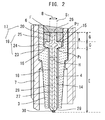
FIG. 2 is an explanatory view showing, in section, a main portion of the spark plug which is the embodiment of the spark plug of the present invention. -
FIGS. 3(a) to 3(c) are explanatory views each showing, in section, a main portion of a center electrode which is one embodiment of the center electrode of the spark plug according to the present invention. -
FIG. 1 shows a spark plug which is one embodiment of the spark plug according to the present invention.FIG. 1 is an overall explanatory view showing, in section, aspark plug 1 which is one embodiment of the spark plug according to the present invention. The axis of an insulator is denoted by the letter O, and, in the following description, the lower direction on the paper on whichFIG. 1 appears is referred to as the forward direction along the axis O, and the upper direction on the paper is referred to as the rearward direction along the axis O. - The
spark plug 1 includes theinsulator 3 having anaxial bore 2 extending in the direction of the axis O; acenter electrode 4 held by aseal material 6 at the forward side of theaxial bore 2; ametal terminal 5 held at the rear side of theaxial bore 2; ametallic shell 7 which accommodates theinsulator 3; and aground electrode 8 whose one end is joined to the forward end surface of themetallic shell 7 and whose other end is disposed in such a manner as to face thecenter electrode 4 via a gap. - The
metallic shell 7 has a substantially cylindrical shape and is formed in such a manner as to accommodate and hold theinsulator 3. Themetallic shell 7 has a threadedportion 9 formed on the outer circumferential surface of its forward portion, and thespark plug 1 is mounted to the cylinder head of an unillustrated internal combustion engine through utilization of the threadedportion 9. Themetallic shell 7 can be formed from an electrically conductive steel material; for example, low-carbon steel. Preferably, in order to reduce the diameter of thespark plug 1, the threadedportion 9 has a size of M12 or less. - The
ground electrode 8 assumes the form of, for example, a substantially rectangular columnar body. The shape and structure of theground electrode 8 are designed as follows: one end of theground electrode 8 is joined to the forward end surface of themetallic shell 7, and the body of theground electrode 8 is bent at an intermediate position so as to assume a shape resembling the letter L and such that a distal end portion of theground electrode 8 faces a forward end portion of thecenter electrode 4 via a gap. Theground electrode 8 is formed from a material similar to that used to form thecenter electrode 4. - The
metal terminal 5 is adapted to apply, to thecenter electrode 4, voltage for performing spark discharge between thecenter electrode 4 and theground electrode 8. Themetal terminal 5 has a flange portion 10 which has an outside diameter greater than the diameter of theaxial bore 2, projects outward from theaxial bore 2, and is partially in contact with the rear end surface, with respect to the direction of the axis O, of theinsulator 3, and a substantially circularcolumnar rod portion 11 which extends forward from the forward end surface, with respect to the direction of the axis O, of the flange portion 10 and is accommodated in theaxial bore 2. Themetal terminal 5 is formed from, for example, low-carbon steel and has an Ni metal layer formed on its surface by plating or the like. - The
insulator 3 is held by an inner circumferential portion of themetallic shell 7 viatalc 12, apacking 13, etc. Theinsulator 3 has a first innercircumferential surface 14 extending at the forward side of theaxial bore 2; a second innercircumferential surface 15 extending at the rear side of theaxial bore 2 and having a diameter greater than that of the first innercircumferential surface 14; and aledge 16 connecting the first innercircumferential surface 14 and the second innercircumferential surface 15. Theinsulator 3 is fixed to themetallic shell 7 in a state in which a forward end portion of theinsulator 3 projects from the forward end surface of themetallic shell 7. Desirably, theinsulator 3 is formed from a material having mechanical strength, thermal strength, electrical strength, etc. An example of such a material is a ceramic sintered body which predominantly contains alumina. - The
center electrode 4 has ahead 17 supported by theledge 16 and extending in a space surrounded by the second innercircumferential surface 15; a circularcolumnar leg 18 extending continuously from the forward end of thehead 17 in a space surrounded by the first innercircumferential surface 14; and aforward end portion 29 extending continuously from the forward end of theleg 18 in such a manner as to be reduced in outside diameter from that of the leg. Thecenter electrode 4 is held in and electrically insulated from themetallic shell 7 in a state in which the forward end of thecenter electrode 4 projects from the forward end surface of theinsulator 3. Thehead 17 has a large-diameter portion 19 projecting radially outward and aprotrusion 20 protruding rearward from the rear end of the large-diameter portion 19. Theforward end portion 29 projects from the forward end surface of theinsulator 3 and has the form of a truncated cone. In the present embodiment, the entireforward end portion 29 projects from the forward end surface of theinsulator 3; however, theforward end portion 29 may partially extend in a space surrounded by the first innercircumferential surface 14. Desirably, thecenter electrode 4 is formed from a material having thermal conductivity, mechanical strength, etc.; for example, thecenter electrode 4 is formed from an Ni-based alloy, such as INCONEL (trade name) 600. Thecenter electrode 4 may have a core 28 enclosed by anouter layer 27 formed from an Ni-based alloy or the like, and formed from a material higher in thermal conductivity than theouter layer 27. Examples of a material used to form the core 28 include Cu, a Cu alloy, Ag, and an Ag alloy. - The
seal material 6 is charged into a space surrounded by theledge 16, the second innercircumferential surface 15, and thehead 17, thereby holding thecenter electrode 4 in theaxial bore 2. Theseal material 6 can be formed by sintering a seal powder which contains a glass powder of soda borosilicate glass and a metal powder of Cu, Fe, or the like. Theseal material 6 usually has a resistance of several hundred mΩ or less. - A
resistor 21 is provided between thecenter electrode 4 and themetal terminal 5 via theseal material 6. Theresistor 21 electrically connects thecenter electrode 4 and themetal terminal 5 and prevents generation of radio noise. Theresistor 21 can be formed by sintering a resistor composition which contains a glass powder of soda borosilicate glass or the like, a ceramic powder of ZrO2 or the like, an electrically-conductive nonmetal powder of carbon black or the like, and/or a metal powder of Zn, Sb, Sn, Ag, Ni, or the like. Theresistor 21 usually has a resistance of 100 Ω or more. - In the present embodiment, a
second seal material 22 formed from a composition similar to that used to form theseal material 6 is provided between theresistor 21 and themetal terminal 5, whereby themetal terminal 5 is fixed, in a sealed condition, to theinsulator 3. The second seal material is provided as needed. In the case where thesecond seal material 22 is not provided, themetal terminal 5 is fixed, in a sealed condition, to theinsulator 3 by means of theresistor 21. - In this spark plug, assuming that, as shown in
FIG. 2 , a position P1 on thecenter electrode 4 is where the outside diameter of thecenter electrode 4 begins to increase, beyond an average outside diameter H of theleg 18, from theleg 18 toward the rear end of thecenter electrode 4, when an axial distance E along the axis from the position P1 to the forward end of thecenter electrode 4 is 15 mm or more, an axial distance A along the axis O from the position P1 to the rear end of thecenter electrode 4 is 3.8 mm or more, preferably 4 mm or more, more preferably 4.5 mm or more. - When the spark plug is subjected to repeated temperature rise and drop in a combustion chamber, the following cycle is repeated: heat of spark discharge generated between the
center electrode 4 and the ground electrode, heat within the combustion chamber, and the like are conducted from the forward end of thecenter electrode 4 to thehead 17 disposed on a side toward the rear end of thecenter electrode 4, whereby the temperature of thehead 17 of thecenter electrode 4 rises; subsequently, thehead 17 stands to cool, whereby the temperature of thehead 17 drops. When such a heating and cooling cycle is repeated, because of the difference in thermal expansion coefficient between a material used to form thecenter electrode 4 and a material used to form theseal material 6, pores are formed in theseal material 6 in a region in the vicinity of the interface between thehead 17 and theseal material 6. In the spark plug, the more the heating and cooling cycle is repeated, and the greater the temperature difference, the greater the thermal expansion of thehead 17, and the more likely the formation of pores. Also, cracking becomes more likely to occur between formed pores. Furthermore, since the operation of an internal combustion engine generates vibration, cracking becomes more likely to occur between formed pores; consequently, a larger void becomes more likely to occur. - However, when the axial distance A falls within the above-mentioned range, thermal expansion of the
head 17 is reduced to thereby restrain formation of pores in theseal material 6, and occurrence of cracking between pores is restrained; therefore, there can be provided a spark plug having good adhesion between thecenter electrode 4 and theseal material 6. Even though such a spark plug is provided in a combustion chamber in which temperature rise and drop are repeated, and a temperature difference involved in temperature rise and drop is large, there is prevented occurrence of loosening and play of thecenter electrode 4 in theaxial bore 2 of theinsulator 3. - Even at the same temperature of a forward end portion of the
center electrode 4, the temperature of thehead 17 varies with the axial distance E, since the amount of heat conducted from the forward end portion to thehead 17 varies. In the case of a short axial distance E of less than 15 mm, suppressing the temperature of thehead 17 to a certain level or less fails; therefore, although the axial distance A is increased, the aforementioned effect fails to be yielded. By contrast, in the case of a long axial distance E of 15 mm or more, the aforementioned effect can be yielded by employing an axial distance A of 3.8 mm or more, preferably 4 mm or more, more preferably 4.5 mm or more. - In the case where a noble-
metal tip 30 formed from a noble metal is provided at the forward end of thecenter electrode 4, the forward end of the noble-metal tip 30 is taken as the forward end of thecenter electrode 4. Therefore, in the case where the noble-metal tip 30 is provided, the axial distance E is an axial distance from the position P1 to the forward end of the noble-metal tip 30. - In the case of an axial distance A of 3.8 mm or less, since the temperature of the
head 17 is apt to increase, thermal expansion of thehead 17 is apt to increase, potentially resulting in formation of pores and occurrence of cracking in theseal material 6. Thus, adhesion between thecenter electrode 4 and theseal material 6 deteriorates. In the case of a long axial distance A, for example, in excess of 5 mm, since the distance between the position of generation of spark discharge and the position of theresistor 21 increases, the effect of restraining generation of radio noise may deteriorate. Therefore, preferably, the axial distance A is 5 mm or less. - The average outside diameter H of the
leg 18 can be measured, for example, as follows. First, a position located 1 mm rearward along the axis O from the forward end of theleg 18 is selected as the measurement start point, and, at the measurement start point, the diameters of theleg 18 are measured in two orthogonal directions. Similarly, the diameters in the two directions are measured at five points, including the measurement start point, located rearward at intervals of 1 mm from the measurement start position. The arithmetical mean of the thus-measured 10 diameters is calculated, thereby yielding the average outside diameter H. - The position P1 is where the diameter of the
center electrode 4 begins to increase, beyond the average outside diameter H, rearward from theleg 18; in other words, the position P1 is the forward end position, with respect to the direction of the axis O, of a region which is located in the vicinity of the boundary between theleg 18 and the large-diameter portion 19 and whose outside diameter measured at any axial position is greater than the average outside diameter H. - In the case of an average outside diameter H of 1.7 mm or more, the effect yielded by the axial distance A being 3.8 mm or more is particularly high. In the case of an average outside diameter H of 1.7 mm or more; i.e., the greater the diameter of the
leg 18, the higher the rate of heat conduction in the rearward direction along the axis O from the forward end of theleg 18; thus, the increased temperature of the forward end of theleg 18 can be quickly lowered, and, therefore, an average outside diameter H of 1.7 mm or more is preferred. Meanwhile, in the case of an average outside diameter H of 1.7 mm or more, the temperature of thehead 17 is apt to increase. Therefore, the aforementioned effect yielded by the axial distance A being 3.8 mm or more is high. Also, theleg 18 can assume any outside diameter so long as theleg 18 can be disposed in theaxial bore 2, and the average outside diameter H is usually 5 mm or less. - As shown in
FIG. 2 , the large-diameter portion 19 has, from the forward side to the rear side along the axis O, a diameter-expandingportion 23, amaximum diameter portion 24, and a diameter-reducingportion 25, and theprotrusion 20 is provided continuously on the rear side of the diameter-reducingportion 25. The diameter-expandingportion 23 is supported by theledge 16, and thecenter electrode 4 is fixed in theaxial bore 2. In the present embodiment, the diameter-expandingportion 23 is formed into a tapered shape; the outer circumferential surface of themaximum diameter portion 24 is formed into a circular columnar shape; and the diameter-reducingportion 25 is formed into a plane which is orthogonal to the axis O and connects the circular columnarmaximum diameter portion 24 and the circularcolumnar protrusion 20 smaller in outside diameter than themaximum diameter portion 24. - In the present embodiment, the
protrusion 20 is formed into a circular columnar shape and has aconical recess 26 formed at its end located opposite the large-diameter portion 19. By virtue of formation of therecess 26, the area of contact between theseal material 6 and thehead 17 increases, thereby facilitating adhesion between theseal material 6 and thehead 17. - No particular limitation is imposed on the shape of the
head 17 so long as thecenter electrode 4 is supported on theledge 16 and fixed in theaxial bore 2; for example, as shown inFIG. 3 , various shapes can be employed for thehead 17. For example, as shown inFIG. 3(a) , the shape of ahead 17a as viewed on the section of acenter electrode 4a taken along the axis O is described, in terms of the contour of thehead 17a, sequentially from the forward side of thecenter electrode 4a: a diameter-expandingportion 23a assumes the form of upward convex curves which continue from the respective rear ends of line segments parallel to the axis O and indicative of aleg 18a; a maximum diameter portion 24a assumes the form of line segments which are parallel to the axis O and continue from the respective rear ends of the curves of the diameter-expandingportion 23a; a diameter-reducingportion 25a assumes the form of downward convex curves which continue from the respective rear ends of the line segments of the maximum diameter portion 24a; and aprotrusion 20a assumes the form of line segments which continue from the respective rear ends of the curves of the diameter-reducingportion 25a and are parallel to the axis O. The contour of ahead portion 17b shown inFIG. 3(b) is as follows: a large-diameter portion 19b assumes the form of curves which continue from the respective rear ends of line segments parallel to the axis O and indicative of aleg 18b and are convex in directions orthogonal to the axis O; and aprotrusion 20b assumes the form of line segments which continue from the respective rear ends of the curves of the large-diameter portion 19b and are parallel to the axis O similar to the case ofFIG. 3(a) . The contour of ahead 17c shown inFIG. 3(c) is as follows: a diameter-expandingportion 23c assumes the form of line segments which continue from the respective rear ends of line segments parallel to the axis O and indicative of aleg 18c and are orthogonal to the line segments of theleg 18c; amaximum diameter portion 24c assumes the form of line segments parallel to the axis O and orthogonal to the line segments of the diameter-expandingportion 23c; a diameter-reducingportion 25c assumes the form of line segments which continue from the respective rear ends of the line segments of the maximum-diameter portion 24c and are inclined with respect to the axis O; and aprotrusion 20c assumes the form of wavy lines which continue from the respective rear ends of the line segments of the diameter-reducingportion 25c and are substantially parallel to the axis O. The contour of theprotrusion 20c assumes the form of wavy lines, since the surface of theprotrusion 20c has undergone thread cutting or like working. Similar to the machined surface of theprotrusion 20c inFIG. 3(c) , the surfaces of the maximum diameter portions 24a to 24c, the surfaces of the diameter-reducingportions 25a to 25c, and the surfaces of theprotrusions 20a to 20c may undergo thread cutting, knurling, or like working so as to have irregularities. - Preferably, the diameter B of an imaginary cylinder S1 which has such a minimum diameter as to be able to surround the
protrusion 20 is smaller than the outside diameter of the large-diameter portion 19 and is 2 mm to 3.3 mm. The greater the outside diameter of theprotrusion 20, the greater the volume of thermal expansion; meanwhile, the greater the outside diameter of theprotrusion 20, the more likely the radiation of heat. Thus, in view of reduction in thermal expansion of theprotrusion 20, preferably, the diameter B of the imaginary cylinder S1 falls within the aforementioned range. Therefore, when the diameter B of the imaginary cylinder S1 falls within the aforementioned range, there can be provided thespark plug 1 having far better adhesion between thecenter electrode 4 and theseal material 6. - Assuming that a position P2 on the
center electrode 4 is of the boundary between the large-diameter portion 19 and theprotrusion 20, preferably, an axial distance C along the axis O between the position P2 and the position P1; i.e., the axial distance C of the large-diameter portion 19, is 0.5 mm to 3 mm. The longer the axial distance C of the large-diameter portion 19 which is greater in outside diameter than theleg portion 18 and theprotrusion 20, the greater the volume of thermal expansion; meanwhile, the longer the axial distance C, the more likely the radiation of heat. Thus, in view of reduction in thermal expansion of the large-diameter portion 19, preferably, the axial distance C falls within the aforementioned range. When the axial distance C falls within the aforementioned range, there can be provided the spark plug having far better adhesion between thecenter electrode 4 and theseal material 6. - The axial distance C is the axial distance between the position P1 and the position P2; the position P1 is stipulated as mentioned above; and the position P2 can be stipulated according to the shape of the
center electrode 4 as follows. The position P2 is the boundary between the large-diameter portion 19 and theprotrusion 20; in other words; the position P2 is a position which is located in the vicinity of the boundary between the large-diameter portion 19 and theprotrusion 20 and where the outside diameter changes. As shown inFIG. 2 andFIGS. 3(b) and 3(c) , in the case of an apparent change in the outside diameter, the position P2 is a position of a greatest change in the outside diameter in the vicinity of the boundary between the large-diameter portion 19 and theprotrusion 20. Meanwhile, as shown inFIG. 3(a) , in the case where a change in the outside diameter is not apparent in the vicinity of the boundary between the large-diameter portion 19 and theprotrusion 20, the position P2 is a position which is located in the vicinity of the boundary between the large-diameter portion 19 and theprotrusion 20 and where the outside diameter begins to increase, beyond the diameter B of the imaginary cylinder S1, along the forward direction of the axis O. - When the inside diameter F of the
insulator 3 as measured at the rear end of thecenter electrode 4 is 3.5 mm or less, particularly 2.9 mm or less, the effect yielded by the axial distance A being 3.8 mm or more is particularly high. An inside diameter F of 3.5 mm or less, particularly 2.9 mm or less, is desirable under the following recent circumstances: in order to attain free engine design, a reduction in the size of an engine, etc., demand has been rising for development of a small-sized spark plug. On the other hand, when the inside diameter F is 3.5 mm or less, particularly 2.9 mm or less, pores are likely to be formed in theseal material 6 in fixing thecenter electrode 4 in theaxial bore 2 in a sealed condition through charge of a seal powder, which is to become theseal material 6, into theaxial bore 2 and subsequent application of heat and pressure, as will be described later, due to difficulty in compressing theseal material 6. Therefore, the effect yielded by the axial distance A being 3.8 mm or more is high. - The
spark plug 1 is manufactured, for example, as follows. First, there are manufactured thecenter electrode 4, theground electrode 8, themetallic shell 7, themetal terminal 5, and theinsulator 3 having respectively predetermined shapes, by publicly known methods. One end portion of theground electrode 8 is joined to the forward end surface of themetallic shell 7 by laser welding or the like. - Meanwhile, the
center electrode 4 is inserted into theaxial bore 2 of theinsulator 3; the diameter-expandingportion 23 of thecenter electrode 4 is seated on theledge 16 of theaxial bore 2; and theleg 18 is disposed in a space surrounded by the first innercircumferential surface 15, and thehead 17 is disposed in a space surrounded by the second inner circumferential surface. - Next, a seal powder used to form the
seal material 6, a resistor composition used to form theresistor 21, and a seal powder used to form thesecond seal material 22 are charged, in this order, into theaxial bore 2 from the rear end of theaxial bore 2; then, a press pin is inserted into theaxial bore 2 and applies a pressure of 60 N/mm2 or more for preliminary compression. - Next, the
rod portion 11 of themetal terminal 5 is inserted into theaxial bore 2 from the rear end of theaxial bore 2, and themetal terminal 5 is disposed such that therod portion 11 is in contact with the seal powder. - Next, while the seal powders and the resistor composition are heated at a temperature equal to or higher than the glass softening point of glass powders contained in the seal powders; for example, at a temperature of 800°C to 1,000°C, for 3 minutes to 30 minutes, the
rod portion 11 of themetal terminal 5 is inserted under pressure until the forward end surface of the flange portion 10 of themetal terminal 5 comes into contact with the rear end surface of theinsulator 3, thereby compression-heating the seal powders and the resistor composition. - In this manner, the
resistor 21, theseal material 6, and thesecond seal material 22 are formed through sintering of the seal powders and the resistor composition, and theseal material 6 and thesecond seal material 22 fix thecenter electrode 4 and themetal terminal 5, respectively, in theaxial bore 2 in a sealed condition. At this time, because of difference in thermal expansion coefficient between thecenter electrode 4 and theseal material 6, a plurality of pores are formed in theseal material 6 in a region in the vicinity of the interface between thecenter electrode 4 and theseal material 6. - Next, the
insulator 3 to which thecenter electrode 4, themetal terminal 5, etc., are fixed is attached to themetallic shell 7 to which theground electrode 8 is joined. - Finally, a distal end portion of the
ground electrode 8 is bent toward thecenter electrode 4 such that one end of theground electrode 8 faces a forward end portion of thecenter electrode 4, thereby completing thespark plug 1. - The spark plug according to the present invention is used as an ignition plug for an internal combustion engine of an automobile, such as a gasoline engine, as follows: the threaded portion of the spark plug is threadingly engaged with a threaded hole provided in a head (not shown) which dividingly forms combustion chambers of the internal combustion engine, whereby the spark plug is fixed at a predetermined position. The spark plug according to the present invention can be used in any type of internal combustion engine; however, the spark plug is particularly effective when used with a combustion chamber having high inside temperature.
- The spark plug according to the present invention is not limited to the above-described embodiment, but may be modified in various other forms, so long as the object of the present invention can be achieved. For example, the spark plug according to the present invention can exhibit good adhesion between the center electrode and the seal material, irrespective of thread diameter, by complying with the aforementioned requirements.
- In the
spark plug 1 of the embodiment described above, thecore 28 is exposed at the rear end surface and at the outer circumferential surface of a rear end portion of thecenter electrode 4; however, thecore 28 may be exposed only at the rear end surface of thecenter electrode 4, or the core 28 may be entirely covered with theouter layer 27 without any exposure. The spark plug according to the present invention can exhibit good adhesion between the center electrode and the seal material, irrespective of state of exposure of the core, by complying with the aforementioned requirements. - The
noble metal tips center electrode 4 and theground electrode 8, respectively; alternatively, the noble metal tip may be provided on only either one of thecenter electrode 4 and theground electrode 8. In thespark plug 1 of the present embodiment, thenoble metal tips center electrode 4 and theground electrode 8, respectively, and a spark discharge gap g is formed between thenoble metal tips - Spark plugs having a shape similar to that of the spark plug shown in
FIG. 1 were manufactured by the aforementioned manufacturing process. Spark plugs having various dimensions shown in Table 1 were manufactured by varying the inside diameter (F) of the insulator, the axial distance (A) from the position P1 to the rear end of the center electrode, the diameter (B) of the imaginary cylinder S1 having such a minimum diameter as to be able to surround the protrusion, the axial distance (C) between the position P1 and the position P2, the axial distance (E) from the position P1 to the forward end of the center electrode, the axial distance (G) from the position P2 to the rear end of the center electrode, and the average outside diameter (H) of the leg. - The various dimensions were measured as follows. The dimension (F) was measured on a fluoroscopic image captured by use of a micro CT scanner (TOSCANER), a product of TOSHIBA. The dimensions (A), (B), (C), (E), (G), and (H) were measured as follows: the center electrodes were removed from the spark plugs, the center electrodes were measured for the dimensions by use of a projector. The dimension (H) was measured as mentioned above; specifically, a position located 1 mm rearward along the axis from the forward end of the circular columnar leg was selected as the measurement start point; diameters of the leg in two directions were measured at five points, including the measurement start point, located rearward at intervals of 1 mm from the measurement start position; and the dimension (H) was calculated from the measured diameters. The dimension (B) was obtained by measuring the maximum diameter of the protrusion of each of the center electrodes.
- The spark plug of test No. 12 in Table 1 had the shape of the center electrode similar to that shown in
FIG. 1 except that thread cutting was performed on the surface of the protrusion of the center electrode. The spark plug of test No. 13 in Table 1 had the shape of the center electrode similar to that shown inFIG. 1 except that the protrusion of the center electrode had a shape machined by use of a three-pawl chuck. The protrusions having these shapes were measured for the dimension (B) as follows: the image of each of the protrusions was captured from a direction orthogonal to the axis of the center electrode by use of a projector, and the maximum width of the protrusion along a radial direction was measured; next, the center electrode was rotated by 60°, and the maximum width of the protrusion was measured; and, similarly, a total of six maximum widths were measured by rotating the center electrode 60° by 60°, and the greatest value of these maximum widths was taken as the dimension (B). - Each of the center electrodes had a core formed from a metal which contained Cu as a main component, and an outer layer which enclosed the core and was formed from a metal which contained Ni as a main component, and the thickness of the outer layer as measured at the position P2 was 0.4 mm.
- The thus-manufactured spark plugs were tested as follows: there was repeated a cycle consisting of applying heat with a burner so as to raise the temperature of a forward end portion of the center electrode to 800°C, conducting the impact test in compliance with Sect. 7.4 of JIS B8031, and allowing to cool. Upon completion of each cycle, the resistance of the resistor of each of the spark plugs was measured. When the R1/R0 value became 0.6 or less, the test was terminated, where R0 is resistance measured at 12 V, and R1 is resistance measured at 3 kV. On the basis of the number of cycles upon termination of the test, adhesion between the center electrode and the seal material was evaluated. Criteria for evaluation are shown below. Table 1 shows the results of the test.
- 1: less than one cycle
- 2: one cycle to less than two cycles
- 3 to 8: two cycles or more; addition of one point per cycle
- 9: nine cycles to less than 10 cycles
- 10: 10 cycles or more
-
[Table 1] Test No. Insulator Center electrode Evaluation results F (mm) A (mm) B (mm) C (mm) E (mm) G (mm) H (mm) 1 Comp. ex. 4.0 3.5 2.9 1.2 17 2.3 2.0 3 2 4.0 3.5 2.9 1.2 15 2.3 2.0 2 3 Example 4.0 3.8 2.9 1.2 15 2.6 2.0 6 4 Comp. ex. 4.0 3.5 2.9 1.2 14 2.3 2.0 1 5 4.0 3.8 2.9 1.2 14 2.6 2.0 2 6 4.0 3.5 2.9 1.2 17 2.3 1.7 3 7 4.0 3.5 2.9 1.2 17 2.3 1.5 4 8 Example 4.0 3.8 2.9 1.2 17 2.6 1.7 7 9 4.0 3.8 2.9 1.2 17 2.6 1.5 8 10 Comp. ex. 3.5 3.5 2.3 1.2 17 2.3 2.0 1 11 3.0 3.5 2.3 1.2 17 2.3 2.0 1 12 3.5 3.5 2.3 1.2 17 2.3 2.0 2 13 Example 4.0 3.8 2.9 1.2 17 2.6 2.0 6 14 3.5 3.8 2.3 1.2 17 2.6 2.0 6 15 4.0 4.0 2.9 1.2 17 2.8 2.0 9 16 4.0 4.0 2 1.2 17 2.8 2.0 9 17 4.0 4.0 3.3 1.2 17 2.8 2.0 9 18 4.0 4.0 1.8 1.2 17 2.8 2.0 8 19 4.0 4.0 3.5 1.2 17 2.8 2.0 8 20 4.0 4.0 2.9 1.2 28 2.8 2.0 10 21 4.0 4.0 2.9 1.0 17 3.0 2.0 9 22 4.0 4.0 2.9 0.5 17 3.5 2.0 9 23 4.0 4.0 2.9 3.0 17 1.0 2.0 9 24 4.0 4.0 2.9 3.5 17 0.5 2.0 8 25 3.5 4.0 2.3 1.2 17 2.8 2.0 9 26 3.5 4.0 1.8 1.2 17 2.8 2.0 8 27 3.0 4.0 2.3 1.2 17 2.8 2.0 9 28 3.0 4.0 1.8 1.2 17 2.8 2.0 8 29 4.0 4.5 2.9 1.2 17 3.3 2.0 9 30 3.5 4.5 2.3 1.2 17 3.3 2.0 9 31 3.0 4.5 2.3 1.2 17 3.3 2.0 9 32 4.0 4.0 2.9 1.2 17 2.8 3.0 9 33 Comp. ex. 2.9 3.5 2.2 1.2 17 2.3 2.0 1 34 Example 2.9 3.8 2.2 1.2 17 2.6 2.0 7 35 2.9 4.0 2.2 1.2 17 2.8 2.0 8 36 2.9 4.5 2.2 1.2 17 3.3 2.0 10 37 Comp. ex. 2.5 3.5 2.0 1.2 17 2.3 2.0 1 38 Example 2.5 3.8 2.0 1.2 17 2.6 2.0 7 39 2.5 4.0 2.0 1.2 17 2.8 2.0 8 40 2.5 4.5 2.0 1.2 17 3.3 2.0 10 - The spark plugs of test Nos. 41 to 52 were tested in a manner similar to that for the spark plugs of test Nos. 1 to 40 except that heat was applied with the burner so as to raise the temperature of the forward end portion of the center electrode to 850°C. Table 2 shows the results of the test.
- ]
[Table 2 Test No. Insulator Center electrode Evaluation results F (mm) A (mm) B (mm) C (mm) E (mm) G (mm) H (mm) 41 Comp. ex. 4.0 3.5 2.9 1.2 18 2.3 2.6 1 42 Example 4.0 4.0 2.9 1.2 18 2.8 2.6 6 43 4.0 4.5 2.9 1.2 18 3.3 2.6 8 44 4.0 5.0 2.9 1.2 18 3.8 2.6 8 45 Comp. ex. 2.9 3.5 2.2 1.2 18 2.3 2.6 1 46 Example 2.9 4.0 2.2 1.2 18 2.8 2.6 5 47 2.9 4.5 2.2 1.2 18 3.3 2.6 8 48 2.9 5.0 2.2 1.2 18 3.8 2.6 8 49 Comp. ex. 2.5 3.5 2 1.2 18 2.3 2.6 1 50 Example 2.5 4.0 2 1.2 18 2.8 2.6 5 51 2.5 4.5 2 1.2 18 3.3 2.6 8 52 2.5 5.0 2 1.2 18 3.8 2.6 8 - As shown in Tables 1 and 2, in spite of repeated heating and cooling cycles, the spark plugs embraced in the scope of the present invention exhibited good adhesion between the center electrode and the seal material and were unlikely to increase in resistance.
-
- 1: spark plug
- 2: axial bore
- 3: insulator
- 4: center electrode
- 5: metal terminal
- 6: seal material
- 7: metallic shell
- 8: ground electrode
- 9: threaded portion
- 10: flange portion
- 11: rod portion
- 12: talc
- 13: packing
- 14: first inner circumferential surface
- 15: second inner circumferential surface
- 16: ledge
- 17: head
- 18: leg
- 19: large-diameter portion
- 20: protrusion
- 21: resistor
- 22: second seal material
- 23: diameter-expanding portion
- 24: maximum diameter portion
- 25: diameter-reducing portion
- 26: recess
- 27: outer layer
- 28: core
- 29: forward end portion
- 30, 31: noble metal tip
Claims (8)
- A spark plug comprising:an insulator having an axial bore extending in a direction of an axis, a first inner circumferential surface extending at a forward side of the axial bore, a second inner circumferential surface extending at a rear side of the axial bore and having a diameter greater than that of the first inner circumferential surface, and a ledge connecting the first inner circumferential surface and the second inner circumferential surface;a center electrode having a head supported by the ledge and extending in a space surrounded by the second inner circumferential surface, and a circular columnar leg extending continuously from a forward end of the head in a space surrounded by the first inner circumferential surface; anda seal material charged into a space surrounded by the ledge, the second inner circumferential surface, and the head to thereby hold the center electrode in the axial bore;the spark plug being characterized in that:assuming that a position P1 on the center electrode is where an outside diameter of the center electrode begins to increase, beyond an average outside diameter H of the leg, from the leg toward a rear end of the center electrode,when an axial distance E along the axis from the position P1 to a forward end of the center electrode is 15 mm or more, an axial distance A along the axis from the position P1 to the rear end of the center electrode is 3.8 mm or more.
- A spark plug according to claim 1, wherein the average outside diameter H is 1.7 mm or more.
- A spark plug according to claim 1 or 2, wherein
the head has a large-diameter portion projecting radially outward and a protrusion protruding rearward from a rear end of the large-diameter portion, and
a diameter B of an imaginary cylinder S1 which has such a minimum diameter as to be able to surround the protrusion is smaller than an outside diameter of the large-diameter portion and is 2 mm to 3.3 mm. - A spark plug according to any one of claims 1 to 3, wherein, assuming that a position P2 on the center electrode is of a boundary between the large-diameter portion and the protrusion, an axial distance C along the axis between the position P2 and the position P1 is 0.5 mm to 3 mm.
- A spark plug according to any one of claims 1 to 4, wherein the axial distance A along the axis is 4 mm or more.
- A spark plug according to any one of claims 1 to 5, wherein an inside diameter F of the insulator as measured at the rear end of the center electrode is 3.5 mm or less.
- A spark plug according to any one of claims 1 to 6, wherein the axial distance A along the axis is 4.5 mm or more.
- A spark plug according to any one of claims 1 to 7, wherein the inside diameter F of the insulator as measured at the rear end of the center electrode is 2.9 mm or less.
Applications Claiming Priority (2)
| Application Number | Priority Date | Filing Date | Title |
|---|---|---|---|
| JP2011020954 | 2011-02-02 | ||
| PCT/JP2012/000687 WO2012105255A1 (en) | 2011-02-02 | 2012-02-01 | Spark plug |
Publications (3)
| Publication Number | Publication Date |
|---|---|
| EP2672587A1 true EP2672587A1 (en) | 2013-12-11 |
| EP2672587A4 EP2672587A4 (en) | 2014-09-03 |
| EP2672587B1 EP2672587B1 (en) | 2019-12-25 |
Family
ID=46602477
Family Applications (2)
| Application Number | Title | Priority Date | Filing Date |
|---|---|---|---|
| EP12742558.5A Active EP2672587B1 (en) | 2011-02-02 | 2012-02-01 | Spark plug |
| EP12742768.0A Active EP2672588B1 (en) | 2011-02-02 | 2012-02-02 | Spark plug |
Family Applications After (1)
| Application Number | Title | Priority Date | Filing Date |
|---|---|---|---|
| EP12742768.0A Active EP2672588B1 (en) | 2011-02-02 | 2012-02-02 | Spark plug |
Country Status (6)
| Country | Link |
|---|---|
| US (2) | US9124073B2 (en) |
| EP (2) | EP2672587B1 (en) |
| JP (2) | JP5414896B2 (en) |
| KR (1) | KR101515314B1 (en) |
| CN (2) | CN103339810A (en) |
| WO (2) | WO2012105255A1 (en) |
Families Citing this family (14)
| Publication number | Priority date | Publication date | Assignee | Title |
|---|---|---|---|---|
| JP2014038773A (en) * | 2012-08-17 | 2014-02-27 | Ngk Spark Plug Co Ltd | Spark plug |
| JP5616946B2 (en) * | 2012-11-28 | 2014-10-29 | 日本特殊陶業株式会社 | Spark plug |
| JP5809673B2 (en) * | 2013-09-09 | 2015-11-11 | 日本特殊陶業株式会社 | Spark plug |
| DE102014223746A1 (en) | 2014-11-20 | 2016-05-25 | Robert Bosch Gmbh | Spark plug and method of making a spark plug |
| DE102014226226A1 (en) * | 2014-12-17 | 2016-06-23 | Robert Bosch Gmbh | A method of manufacturing a spark plug electrode having a core extending to the firing surface |
| JP6157519B2 (en) * | 2015-01-27 | 2017-07-05 | 日本特殊陶業株式会社 | Spark plug |
| JP5963908B1 (en) * | 2015-04-28 | 2016-08-03 | 日本特殊陶業株式会社 | Spark plug |
| JP6087991B2 (en) | 2015-06-22 | 2017-03-01 | 日本特殊陶業株式会社 | Spark plug |
| JP6087990B2 (en) | 2015-06-22 | 2017-03-01 | 日本特殊陶業株式会社 | Spark plug |
| JP6025921B1 (en) * | 2015-06-22 | 2016-11-16 | 日本特殊陶業株式会社 | Spark plug |
| US9570889B2 (en) * | 2015-07-15 | 2017-02-14 | Ngk Spark Plug Co., Ltd. | Spark plug |
| JP6490025B2 (en) * | 2016-04-25 | 2019-03-27 | 日本特殊陶業株式会社 | Spark plug |
| JP6970779B2 (en) | 2020-04-20 | 2021-11-24 | 日本特殊陶業株式会社 | Spark plug |
| JP2022045383A (en) * | 2020-09-09 | 2022-03-22 | 日本特殊陶業株式会社 | Spark plug |
Citations (4)
| Publication number | Priority date | Publication date | Assignee | Title |
|---|---|---|---|---|
| JPS4844701B1 (en) * | 1970-03-20 | 1973-12-26 | ||
| JPH02165587A (en) * | 1988-12-20 | 1990-06-26 | Ngk Spark Plug Co Ltd | Central electrode for spark plug |
| JP2001313148A (en) * | 2000-05-01 | 2001-11-09 | Ngk Spark Plug Co Ltd | Spark plug |
| WO2010131410A1 (en) * | 2009-05-13 | 2010-11-18 | 日本特殊陶業株式会社 | Spark plug |
Family Cites Families (12)
| Publication number | Priority date | Publication date | Assignee | Title |
|---|---|---|---|---|
| JPS4844701A (en) | 1971-10-09 | 1973-06-27 | ||
| JP3079383B2 (en) * | 1990-09-29 | 2000-08-21 | 日本特殊陶業株式会社 | Spark plug for internal combustion engine |
| JPH0844701A (en) * | 1994-08-02 | 1996-02-16 | Hirohiko Adachi | Method for predicting electron state of compound having structural defect |
| JP3497009B2 (en) | 1995-05-16 | 2004-02-16 | 日本特殊陶業株式会社 | Spark plug |
| JP3500555B2 (en) | 1996-03-29 | 2004-02-23 | 日本特殊陶業株式会社 | Spark plug for internal combustion engine |
| US6191525B1 (en) * | 1997-08-27 | 2001-02-20 | Ngk Spark Plug Co., Ltd. | Spark plug |
| EP1298768B1 (en) * | 2001-03-28 | 2011-12-21 | NGK Spark Plug Co., Ltd. | Spark plug |
| JP3795374B2 (en) * | 2001-10-31 | 2006-07-12 | 日本特殊陶業株式会社 | Spark plug |
| US20050168121A1 (en) * | 2004-02-03 | 2005-08-04 | Federal-Mogul Ignition (U.K.) Limited | Spark plug configuration having a metal noble tip |
| US7365480B2 (en) | 2004-04-30 | 2008-04-29 | Ngk Spark Plug Co., Ltd. | Spark plug |
| JP4719191B2 (en) * | 2007-07-17 | 2011-07-06 | 日本特殊陶業株式会社 | Spark plug for internal combustion engine |
| CN201219174Y (en) | 2008-03-27 | 2009-04-08 | 张文峯 | Spark plug |
-
2012
- 2012-02-01 EP EP12742558.5A patent/EP2672587B1/en active Active
- 2012-02-01 JP JP2012523529A patent/JP5414896B2/en active Active
- 2012-02-01 WO PCT/JP2012/000687 patent/WO2012105255A1/en active Application Filing
- 2012-02-01 KR KR1020137022928A patent/KR101515314B1/en active IP Right Grant
- 2012-02-01 CN CN2012800075948A patent/CN103339810A/en active Pending
- 2012-02-01 US US13/983,073 patent/US9124073B2/en active Active
- 2012-02-02 EP EP12742768.0A patent/EP2672588B1/en active Active
- 2012-02-02 JP JP2012523532A patent/JP5414897B2/en active Active
- 2012-02-02 WO PCT/JP2012/000721 patent/WO2012105270A1/en active Application Filing
- 2012-02-02 CN CN201280007532.7A patent/CN103339809B/en active Active
- 2012-02-02 US US13/978,976 patent/US8963407B2/en active Active
Patent Citations (4)
| Publication number | Priority date | Publication date | Assignee | Title |
|---|---|---|---|---|
| JPS4844701B1 (en) * | 1970-03-20 | 1973-12-26 | ||
| JPH02165587A (en) * | 1988-12-20 | 1990-06-26 | Ngk Spark Plug Co Ltd | Central electrode for spark plug |
| JP2001313148A (en) * | 2000-05-01 | 2001-11-09 | Ngk Spark Plug Co Ltd | Spark plug |
| WO2010131410A1 (en) * | 2009-05-13 | 2010-11-18 | 日本特殊陶業株式会社 | Spark plug |
Non-Patent Citations (1)
| Title |
|---|
| See also references of WO2012105255A1 * |
Also Published As
| Publication number | Publication date |
|---|---|
| WO2012105270A1 (en) | 2012-08-09 |
| KR20130120531A (en) | 2013-11-04 |
| WO2012105255A1 (en) | 2012-08-09 |
| JP5414897B2 (en) | 2014-02-12 |
| US20130285534A1 (en) | 2013-10-31 |
| EP2672587B1 (en) | 2019-12-25 |
| EP2672588A4 (en) | 2016-11-02 |
| US8963407B2 (en) | 2015-02-24 |
| JPWO2012105255A1 (en) | 2014-07-03 |
| CN103339810A (en) | 2013-10-02 |
| US9124073B2 (en) | 2015-09-01 |
| EP2672588B1 (en) | 2017-11-29 |
| JPWO2012105270A1 (en) | 2014-07-03 |
| US20130307402A1 (en) | 2013-11-21 |
| CN103339809B (en) | 2015-07-22 |
| EP2672587A4 (en) | 2014-09-03 |
| EP2672588A1 (en) | 2013-12-11 |
| CN103339809A (en) | 2013-10-02 |
| KR101515314B1 (en) | 2015-04-24 |
| JP5414896B2 (en) | 2014-02-12 |
Similar Documents
| Publication | Publication Date | Title |
|---|---|---|
| EP2672587B1 (en) | Spark plug | |
| EP2408071B1 (en) | Spark plug for internal combustion engine and method of manufacturing same | |
| EP2388792A1 (en) | Spark plug | |
| EP2560255B1 (en) | Spark plug for internal combustion engine and method of manufacturing spark plug | |
| EP2381546B1 (en) | Spark plug for internal combustion engine | |
| EP2741382B1 (en) | Ignition plug | |
| EP2833492B1 (en) | Spark plug | |
| US9160147B2 (en) | Spark plug and manufacturing method for same | |
| EP2400606A1 (en) | Spark plug for internal combustion engine | |
| US10777975B2 (en) | Spark plug | |
| EP3252890B1 (en) | Spark plug | |
| JP5616858B2 (en) | Spark plug | |
| US8922104B1 (en) | Spark plug having an embedded tip that is prevented from detachment due to thermal stress | |
| JP5401426B2 (en) | Manufacturing method of spark plug | |
| EP3065238B1 (en) | Spark plug | |
| EP2568548B1 (en) | Method of manufacturing a spark plug | |
| EP2624383B1 (en) | Spark plug | |
| EP3419124B1 (en) | Spark plug |
Legal Events
| Date | Code | Title | Description |
|---|---|---|---|
| PUAI | Public reference made under article 153(3) epc to a published international application that has entered the european phase |
Free format text: ORIGINAL CODE: 0009012 |
|
| 17P | Request for examination filed |
Effective date: 20130902 |
|
| AK | Designated contracting states |
Kind code of ref document: A1 Designated state(s): AL AT BE BG CH CY CZ DE DK EE ES FI FR GB GR HR HU IE IS IT LI LT LU LV MC MK MT NL NO PL PT RO RS SE SI SK SM TR |
|
| DAX | Request for extension of the european patent (deleted) | ||
| A4 | Supplementary search report drawn up and despatched |
Effective date: 20140805 |
|
| RIC1 | Information provided on ipc code assigned before grant |
Ipc: H01T 13/34 20060101ALI20140730BHEP Ipc: H01T 13/20 20060101AFI20140730BHEP |
|
| GRAP | Despatch of communication of intention to grant a patent |
Free format text: ORIGINAL CODE: EPIDOSNIGR1 |
|
| STAA | Information on the status of an ep patent application or granted ep patent |
Free format text: STATUS: GRANT OF PATENT IS INTENDED |
|
| INTG | Intention to grant announced |
Effective date: 20190802 |
|
| GRAS | Grant fee paid |
Free format text: ORIGINAL CODE: EPIDOSNIGR3 |
|
| GRAA | (expected) grant |
Free format text: ORIGINAL CODE: 0009210 |
|
| STAA | Information on the status of an ep patent application or granted ep patent |
Free format text: STATUS: THE PATENT HAS BEEN GRANTED |
|
| AK | Designated contracting states |
Kind code of ref document: B1 Designated state(s): AL AT BE BG CH CY CZ DE DK EE ES FI FR GB GR HR HU IE IS IT LI LT LU LV MC MK MT NL NO PL PT RO RS SE SI SK SM TR |
|
| REG | Reference to a national code |
Ref country code: GB Ref legal event code: FG4D |
|
| REG | Reference to a national code |
Ref country code: CH Ref legal event code: EP |
|
| REG | Reference to a national code |
Ref country code: DE Ref legal event code: R096 Ref document number: 602012066707 Country of ref document: DE |
|
| REG | Reference to a national code |
Ref country code: AT Ref legal event code: REF Ref document number: 1218174 Country of ref document: AT Kind code of ref document: T Effective date: 20200115 |
|
| REG | Reference to a national code |
Ref country code: IE Ref legal event code: FG4D |
|
| REG | Reference to a national code |
Ref country code: NL Ref legal event code: MP Effective date: 20191225 |
|
| PG25 | Lapsed in a contracting state [announced via postgrant information from national office to epo] |
Ref country code: NO Free format text: LAPSE BECAUSE OF FAILURE TO SUBMIT A TRANSLATION OF THE DESCRIPTION OR TO PAY THE FEE WITHIN THE PRESCRIBED TIME-LIMIT Effective date: 20200325 Ref country code: GR Free format text: LAPSE BECAUSE OF FAILURE TO SUBMIT A TRANSLATION OF THE DESCRIPTION OR TO PAY THE FEE WITHIN THE PRESCRIBED TIME-LIMIT Effective date: 20200326 Ref country code: BG Free format text: LAPSE BECAUSE OF FAILURE TO SUBMIT A TRANSLATION OF THE DESCRIPTION OR TO PAY THE FEE WITHIN THE PRESCRIBED TIME-LIMIT Effective date: 20200325 Ref country code: LT Free format text: LAPSE BECAUSE OF FAILURE TO SUBMIT A TRANSLATION OF THE DESCRIPTION OR TO PAY THE FEE WITHIN THE PRESCRIBED TIME-LIMIT Effective date: 20191225 Ref country code: FI Free format text: LAPSE BECAUSE OF FAILURE TO SUBMIT A TRANSLATION OF THE DESCRIPTION OR TO PAY THE FEE WITHIN THE PRESCRIBED TIME-LIMIT Effective date: 20191225 Ref country code: LV Free format text: LAPSE BECAUSE OF FAILURE TO SUBMIT A TRANSLATION OF THE DESCRIPTION OR TO PAY THE FEE WITHIN THE PRESCRIBED TIME-LIMIT Effective date: 20191225 Ref country code: SE Free format text: LAPSE BECAUSE OF FAILURE TO SUBMIT A TRANSLATION OF THE DESCRIPTION OR TO PAY THE FEE WITHIN THE PRESCRIBED TIME-LIMIT Effective date: 20191225 |
|
| REG | Reference to a national code |
Ref country code: LT Ref legal event code: MG4D |
|
| PG25 | Lapsed in a contracting state [announced via postgrant information from national office to epo] |
Ref country code: RS Free format text: LAPSE BECAUSE OF FAILURE TO SUBMIT A TRANSLATION OF THE DESCRIPTION OR TO PAY THE FEE WITHIN THE PRESCRIBED TIME-LIMIT Effective date: 20191225 Ref country code: HR Free format text: LAPSE BECAUSE OF FAILURE TO SUBMIT A TRANSLATION OF THE DESCRIPTION OR TO PAY THE FEE WITHIN THE PRESCRIBED TIME-LIMIT Effective date: 20191225 |
|
| PG25 | Lapsed in a contracting state [announced via postgrant information from national office to epo] |
Ref country code: AL Free format text: LAPSE BECAUSE OF FAILURE TO SUBMIT A TRANSLATION OF THE DESCRIPTION OR TO PAY THE FEE WITHIN THE PRESCRIBED TIME-LIMIT Effective date: 20191225 |
|
| PG25 | Lapsed in a contracting state [announced via postgrant information from national office to epo] |
Ref country code: EE Free format text: LAPSE BECAUSE OF FAILURE TO SUBMIT A TRANSLATION OF THE DESCRIPTION OR TO PAY THE FEE WITHIN THE PRESCRIBED TIME-LIMIT Effective date: 20191225 Ref country code: CZ Free format text: LAPSE BECAUSE OF FAILURE TO SUBMIT A TRANSLATION OF THE DESCRIPTION OR TO PAY THE FEE WITHIN THE PRESCRIBED TIME-LIMIT Effective date: 20191225 Ref country code: NL Free format text: LAPSE BECAUSE OF FAILURE TO SUBMIT A TRANSLATION OF THE DESCRIPTION OR TO PAY THE FEE WITHIN THE PRESCRIBED TIME-LIMIT Effective date: 20191225 Ref country code: RO Free format text: LAPSE BECAUSE OF FAILURE TO SUBMIT A TRANSLATION OF THE DESCRIPTION OR TO PAY THE FEE WITHIN THE PRESCRIBED TIME-LIMIT Effective date: 20191225 Ref country code: PT Free format text: LAPSE BECAUSE OF FAILURE TO SUBMIT A TRANSLATION OF THE DESCRIPTION OR TO PAY THE FEE WITHIN THE PRESCRIBED TIME-LIMIT Effective date: 20200520 |
|
| PG25 | Lapsed in a contracting state [announced via postgrant information from national office to epo] |
Ref country code: SK Free format text: LAPSE BECAUSE OF FAILURE TO SUBMIT A TRANSLATION OF THE DESCRIPTION OR TO PAY THE FEE WITHIN THE PRESCRIBED TIME-LIMIT Effective date: 20191225 Ref country code: SM Free format text: LAPSE BECAUSE OF FAILURE TO SUBMIT A TRANSLATION OF THE DESCRIPTION OR TO PAY THE FEE WITHIN THE PRESCRIBED TIME-LIMIT Effective date: 20191225 Ref country code: IS Free format text: LAPSE BECAUSE OF FAILURE TO SUBMIT A TRANSLATION OF THE DESCRIPTION OR TO PAY THE FEE WITHIN THE PRESCRIBED TIME-LIMIT Effective date: 20200425 |
|
| REG | Reference to a national code |
Ref country code: DE Ref legal event code: R097 Ref document number: 602012066707 Country of ref document: DE |
|
| REG | Reference to a national code |
Ref country code: CH Ref legal event code: PL |
|
| REG | Reference to a national code |
Ref country code: BE Ref legal event code: MM Effective date: 20200229 |
|
| PG25 | Lapsed in a contracting state [announced via postgrant information from national office to epo] |
Ref country code: DK Free format text: LAPSE BECAUSE OF FAILURE TO SUBMIT A TRANSLATION OF THE DESCRIPTION OR TO PAY THE FEE WITHIN THE PRESCRIBED TIME-LIMIT Effective date: 20191225 Ref country code: MC Free format text: LAPSE BECAUSE OF FAILURE TO SUBMIT A TRANSLATION OF THE DESCRIPTION OR TO PAY THE FEE WITHIN THE PRESCRIBED TIME-LIMIT Effective date: 20191225 Ref country code: ES Free format text: LAPSE BECAUSE OF FAILURE TO SUBMIT A TRANSLATION OF THE DESCRIPTION OR TO PAY THE FEE WITHIN THE PRESCRIBED TIME-LIMIT Effective date: 20191225 Ref country code: LU Free format text: LAPSE BECAUSE OF NON-PAYMENT OF DUE FEES Effective date: 20200201 |
|
| PLBE | No opposition filed within time limit |
Free format text: ORIGINAL CODE: 0009261 |
|
| STAA | Information on the status of an ep patent application or granted ep patent |
Free format text: STATUS: NO OPPOSITION FILED WITHIN TIME LIMIT |
|
| REG | Reference to a national code |
Ref country code: AT Ref legal event code: MK05 Ref document number: 1218174 Country of ref document: AT Kind code of ref document: T Effective date: 20191225 |
|
| PG25 | Lapsed in a contracting state [announced via postgrant information from national office to epo] |
Ref country code: CH Free format text: LAPSE BECAUSE OF NON-PAYMENT OF DUE FEES Effective date: 20200229 Ref country code: LI Free format text: LAPSE BECAUSE OF NON-PAYMENT OF DUE FEES Effective date: 20200229 Ref country code: SI Free format text: LAPSE BECAUSE OF FAILURE TO SUBMIT A TRANSLATION OF THE DESCRIPTION OR TO PAY THE FEE WITHIN THE PRESCRIBED TIME-LIMIT Effective date: 20191225 |
|
| 26N | No opposition filed |
Effective date: 20200928 |
|
| PG25 | Lapsed in a contracting state [announced via postgrant information from national office to epo] |
Ref country code: IT Free format text: LAPSE BECAUSE OF FAILURE TO SUBMIT A TRANSLATION OF THE DESCRIPTION OR TO PAY THE FEE WITHIN THE PRESCRIBED TIME-LIMIT Effective date: 20191225 Ref country code: FR Free format text: LAPSE BECAUSE OF NON-PAYMENT OF DUE FEES Effective date: 20200225 Ref country code: IE Free format text: LAPSE BECAUSE OF NON-PAYMENT OF DUE FEES Effective date: 20200201 Ref country code: AT Free format text: LAPSE BECAUSE OF FAILURE TO SUBMIT A TRANSLATION OF THE DESCRIPTION OR TO PAY THE FEE WITHIN THE PRESCRIBED TIME-LIMIT Effective date: 20191225 |
|
| PG25 | Lapsed in a contracting state [announced via postgrant information from national office to epo] |
Ref country code: PL Free format text: LAPSE BECAUSE OF FAILURE TO SUBMIT A TRANSLATION OF THE DESCRIPTION OR TO PAY THE FEE WITHIN THE PRESCRIBED TIME-LIMIT Effective date: 20191225 Ref country code: BE Free format text: LAPSE BECAUSE OF NON-PAYMENT OF DUE FEES Effective date: 20200229 |
|
| GBPC | Gb: european patent ceased through non-payment of renewal fee |
Effective date: 20200325 |
|
| PG25 | Lapsed in a contracting state [announced via postgrant information from national office to epo] |
Ref country code: GB Free format text: LAPSE BECAUSE OF NON-PAYMENT OF DUE FEES Effective date: 20200325 |
|
| PG25 | Lapsed in a contracting state [announced via postgrant information from national office to epo] |
Ref country code: TR Free format text: LAPSE BECAUSE OF FAILURE TO SUBMIT A TRANSLATION OF THE DESCRIPTION OR TO PAY THE FEE WITHIN THE PRESCRIBED TIME-LIMIT Effective date: 20191225 Ref country code: MT Free format text: LAPSE BECAUSE OF FAILURE TO SUBMIT A TRANSLATION OF THE DESCRIPTION OR TO PAY THE FEE WITHIN THE PRESCRIBED TIME-LIMIT Effective date: 20191225 Ref country code: CY Free format text: LAPSE BECAUSE OF FAILURE TO SUBMIT A TRANSLATION OF THE DESCRIPTION OR TO PAY THE FEE WITHIN THE PRESCRIBED TIME-LIMIT Effective date: 20191225 |
|
| PG25 | Lapsed in a contracting state [announced via postgrant information from national office to epo] |
Ref country code: MK Free format text: LAPSE BECAUSE OF FAILURE TO SUBMIT A TRANSLATION OF THE DESCRIPTION OR TO PAY THE FEE WITHIN THE PRESCRIBED TIME-LIMIT Effective date: 20191225 |
|
| P01 | Opt-out of the competence of the unified patent court (upc) registered |
Effective date: 20230512 |
|
| REG | Reference to a national code |
Ref country code: DE Ref legal event code: R081 Ref document number: 602012066707 Country of ref document: DE Owner name: NITERRA CO., LTD., NAGOYA-SHI, JP Free format text: FORMER OWNER: NGK SPARK PLUG CO., LTD., NAGOYA-SHI, AICHI, JP |
|
| PGFP | Annual fee paid to national office [announced via postgrant information from national office to epo] |
Ref country code: DE Payment date: 20231228 Year of fee payment: 13 |