EP2672284A2 - Voltage sensing assembly and battery module having same - Google Patents
Voltage sensing assembly and battery module having same Download PDFInfo
- Publication number
- EP2672284A2 EP2672284A2 EP12785388.5A EP12785388A EP2672284A2 EP 2672284 A2 EP2672284 A2 EP 2672284A2 EP 12785388 A EP12785388 A EP 12785388A EP 2672284 A2 EP2672284 A2 EP 2672284A2
- Authority
- EP
- European Patent Office
- Prior art keywords
- voltage sensing
- bus bars
- sensing assembly
- battery module
- battery
- Prior art date
- Legal status (The legal status is an assumption and is not a legal conclusion. Google has not performed a legal analysis and makes no representation as to the accuracy of the status listed.)
- Granted
Links
Images


Classifications
-
- G—PHYSICS
- G01—MEASURING; TESTING
- G01R—MEASURING ELECTRIC VARIABLES; MEASURING MAGNETIC VARIABLES
- G01R31/00—Arrangements for testing electric properties; Arrangements for locating electric faults; Arrangements for electrical testing characterised by what is being tested not provided for elsewhere
- G01R31/36—Arrangements for testing, measuring or monitoring the electrical condition of accumulators or electric batteries, e.g. capacity or state of charge [SoC]
- G01R31/382—Arrangements for monitoring battery or accumulator variables, e.g. SoC
- G01R31/3835—Arrangements for monitoring battery or accumulator variables, e.g. SoC involving only voltage measurements
-
- G—PHYSICS
- G01—MEASURING; TESTING
- G01R—MEASURING ELECTRIC VARIABLES; MEASURING MAGNETIC VARIABLES
- G01R19/00—Arrangements for measuring currents or voltages or for indicating presence or sign thereof
- G01R19/165—Indicating that current or voltage is either above or below a predetermined value or within or outside a predetermined range of values
-
- G—PHYSICS
- G01—MEASURING; TESTING
- G01R—MEASURING ELECTRIC VARIABLES; MEASURING MAGNETIC VARIABLES
- G01R31/00—Arrangements for testing electric properties; Arrangements for locating electric faults; Arrangements for electrical testing characterised by what is being tested not provided for elsewhere
- G01R31/34—Testing dynamo-electric machines
-
- G—PHYSICS
- G01—MEASURING; TESTING
- G01R—MEASURING ELECTRIC VARIABLES; MEASURING MAGNETIC VARIABLES
- G01R31/00—Arrangements for testing electric properties; Arrangements for locating electric faults; Arrangements for electrical testing characterised by what is being tested not provided for elsewhere
- G01R31/36—Arrangements for testing, measuring or monitoring the electrical condition of accumulators or electric batteries, e.g. capacity or state of charge [SoC]
- G01R31/364—Battery terminal connectors with integrated measuring arrangements
-
- G—PHYSICS
- G01—MEASURING; TESTING
- G01R—MEASURING ELECTRIC VARIABLES; MEASURING MAGNETIC VARIABLES
- G01R31/00—Arrangements for testing electric properties; Arrangements for locating electric faults; Arrangements for electrical testing characterised by what is being tested not provided for elsewhere
- G01R31/36—Arrangements for testing, measuring or monitoring the electrical condition of accumulators or electric batteries, e.g. capacity or state of charge [SoC]
- G01R31/385—Arrangements for measuring battery or accumulator variables
-
- G—PHYSICS
- G01—MEASURING; TESTING
- G01R—MEASURING ELECTRIC VARIABLES; MEASURING MAGNETIC VARIABLES
- G01R31/00—Arrangements for testing electric properties; Arrangements for locating electric faults; Arrangements for electrical testing characterised by what is being tested not provided for elsewhere
- G01R31/36—Arrangements for testing, measuring or monitoring the electrical condition of accumulators or electric batteries, e.g. capacity or state of charge [SoC]
- G01R31/396—Acquisition or processing of data for testing or for monitoring individual cells or groups of cells within a battery
-
- H—ELECTRICITY
- H01—ELECTRIC ELEMENTS
- H01M—PROCESSES OR MEANS, e.g. BATTERIES, FOR THE DIRECT CONVERSION OF CHEMICAL ENERGY INTO ELECTRICAL ENERGY
- H01M10/00—Secondary cells; Manufacture thereof
- H01M10/42—Methods or arrangements for servicing or maintenance of secondary cells or secondary half-cells
- H01M10/48—Accumulators combined with arrangements for measuring, testing or indicating the condition of cells, e.g. the level or density of the electrolyte
- H01M10/482—Accumulators combined with arrangements for measuring, testing or indicating the condition of cells, e.g. the level or density of the electrolyte for several batteries or cells simultaneously or sequentially
-
- H—ELECTRICITY
- H01—ELECTRIC ELEMENTS
- H01M—PROCESSES OR MEANS, e.g. BATTERIES, FOR THE DIRECT CONVERSION OF CHEMICAL ENERGY INTO ELECTRICAL ENERGY
- H01M10/00—Secondary cells; Manufacture thereof
- H01M10/60—Heating or cooling; Temperature control
- H01M10/61—Types of temperature control
- H01M10/613—Cooling or keeping cold
-
- H—ELECTRICITY
- H01—ELECTRIC ELEMENTS
- H01M—PROCESSES OR MEANS, e.g. BATTERIES, FOR THE DIRECT CONVERSION OF CHEMICAL ENERGY INTO ELECTRICAL ENERGY
- H01M10/00—Secondary cells; Manufacture thereof
- H01M10/60—Heating or cooling; Temperature control
- H01M10/65—Means for temperature control structurally associated with the cells
- H01M10/655—Solid structures for heat exchange or heat conduction
- H01M10/6554—Rods or plates
- H01M10/6555—Rods or plates arranged between the cells
-
- H—ELECTRICITY
- H01—ELECTRIC ELEMENTS
- H01M—PROCESSES OR MEANS, e.g. BATTERIES, FOR THE DIRECT CONVERSION OF CHEMICAL ENERGY INTO ELECTRICAL ENERGY
- H01M50/00—Constructional details or processes of manufacture of the non-active parts of electrochemical cells other than fuel cells, e.g. hybrid cells
- H01M50/10—Primary casings, jackets or wrappings of a single cell or a single battery
- H01M50/116—Primary casings, jackets or wrappings of a single cell or a single battery characterised by the material
- H01M50/117—Inorganic material
- H01M50/119—Metals
-
- H—ELECTRICITY
- H01—ELECTRIC ELEMENTS
- H01M—PROCESSES OR MEANS, e.g. BATTERIES, FOR THE DIRECT CONVERSION OF CHEMICAL ENERGY INTO ELECTRICAL ENERGY
- H01M50/00—Constructional details or processes of manufacture of the non-active parts of electrochemical cells other than fuel cells, e.g. hybrid cells
- H01M50/10—Primary casings, jackets or wrappings of a single cell or a single battery
- H01M50/116—Primary casings, jackets or wrappings of a single cell or a single battery characterised by the material
- H01M50/121—Organic material
-
- H—ELECTRICITY
- H01—ELECTRIC ELEMENTS
- H01M—PROCESSES OR MEANS, e.g. BATTERIES, FOR THE DIRECT CONVERSION OF CHEMICAL ENERGY INTO ELECTRICAL ENERGY
- H01M50/00—Constructional details or processes of manufacture of the non-active parts of electrochemical cells other than fuel cells, e.g. hybrid cells
- H01M50/10—Primary casings, jackets or wrappings of a single cell or a single battery
- H01M50/116—Primary casings, jackets or wrappings of a single cell or a single battery characterised by the material
- H01M50/124—Primary casings, jackets or wrappings of a single cell or a single battery characterised by the material having a layered structure
-
- H—ELECTRICITY
- H01—ELECTRIC ELEMENTS
- H01M—PROCESSES OR MEANS, e.g. BATTERIES, FOR THE DIRECT CONVERSION OF CHEMICAL ENERGY INTO ELECTRICAL ENERGY
- H01M50/00—Constructional details or processes of manufacture of the non-active parts of electrochemical cells other than fuel cells, e.g. hybrid cells
- H01M50/20—Mountings; Secondary casings or frames; Racks, modules or packs; Suspension devices; Shock absorbers; Transport or carrying devices; Holders
- H01M50/204—Racks, modules or packs for multiple batteries or multiple cells
- H01M50/207—Racks, modules or packs for multiple batteries or multiple cells characterised by their shape
- H01M50/211—Racks, modules or packs for multiple batteries or multiple cells characterised by their shape adapted for pouch cells
-
- H—ELECTRICITY
- H01—ELECTRIC ELEMENTS
- H01M—PROCESSES OR MEANS, e.g. BATTERIES, FOR THE DIRECT CONVERSION OF CHEMICAL ENERGY INTO ELECTRICAL ENERGY
- H01M50/00—Constructional details or processes of manufacture of the non-active parts of electrochemical cells other than fuel cells, e.g. hybrid cells
- H01M50/20—Mountings; Secondary casings or frames; Racks, modules or packs; Suspension devices; Shock absorbers; Transport or carrying devices; Holders
- H01M50/262—Mountings; Secondary casings or frames; Racks, modules or packs; Suspension devices; Shock absorbers; Transport or carrying devices; Holders with fastening means, e.g. locks
- H01M50/264—Mountings; Secondary casings or frames; Racks, modules or packs; Suspension devices; Shock absorbers; Transport or carrying devices; Holders with fastening means, e.g. locks for cells or batteries, e.g. straps, tie rods or peripheral frames
-
- H—ELECTRICITY
- H01—ELECTRIC ELEMENTS
- H01M—PROCESSES OR MEANS, e.g. BATTERIES, FOR THE DIRECT CONVERSION OF CHEMICAL ENERGY INTO ELECTRICAL ENERGY
- H01M50/00—Constructional details or processes of manufacture of the non-active parts of electrochemical cells other than fuel cells, e.g. hybrid cells
- H01M50/20—Mountings; Secondary casings or frames; Racks, modules or packs; Suspension devices; Shock absorbers; Transport or carrying devices; Holders
- H01M50/289—Mountings; Secondary casings or frames; Racks, modules or packs; Suspension devices; Shock absorbers; Transport or carrying devices; Holders characterised by spacing elements or positioning means within frames, racks or packs
- H01M50/291—Mountings; Secondary casings or frames; Racks, modules or packs; Suspension devices; Shock absorbers; Transport or carrying devices; Holders characterised by spacing elements or positioning means within frames, racks or packs characterised by their shape
-
- H—ELECTRICITY
- H01—ELECTRIC ELEMENTS
- H01M—PROCESSES OR MEANS, e.g. BATTERIES, FOR THE DIRECT CONVERSION OF CHEMICAL ENERGY INTO ELECTRICAL ENERGY
- H01M50/00—Constructional details or processes of manufacture of the non-active parts of electrochemical cells other than fuel cells, e.g. hybrid cells
- H01M50/20—Mountings; Secondary casings or frames; Racks, modules or packs; Suspension devices; Shock absorbers; Transport or carrying devices; Holders
- H01M50/296—Mountings; Secondary casings or frames; Racks, modules or packs; Suspension devices; Shock absorbers; Transport or carrying devices; Holders characterised by terminals of battery packs
-
- H—ELECTRICITY
- H01—ELECTRIC ELEMENTS
- H01M—PROCESSES OR MEANS, e.g. BATTERIES, FOR THE DIRECT CONVERSION OF CHEMICAL ENERGY INTO ELECTRICAL ENERGY
- H01M50/00—Constructional details or processes of manufacture of the non-active parts of electrochemical cells other than fuel cells, e.g. hybrid cells
- H01M50/20—Mountings; Secondary casings or frames; Racks, modules or packs; Suspension devices; Shock absorbers; Transport or carrying devices; Holders
- H01M50/298—Mountings; Secondary casings or frames; Racks, modules or packs; Suspension devices; Shock absorbers; Transport or carrying devices; Holders characterised by the wiring of battery packs
-
- H—ELECTRICITY
- H01—ELECTRIC ELEMENTS
- H01M—PROCESSES OR MEANS, e.g. BATTERIES, FOR THE DIRECT CONVERSION OF CHEMICAL ENERGY INTO ELECTRICAL ENERGY
- H01M50/00—Constructional details or processes of manufacture of the non-active parts of electrochemical cells other than fuel cells, e.g. hybrid cells
- H01M50/50—Current conducting connections for cells or batteries
- H01M50/569—Constructional details of current conducting connections for detecting conditions inside cells or batteries, e.g. details of voltage sensing terminals
-
- B—PERFORMING OPERATIONS; TRANSPORTING
- B60—VEHICLES IN GENERAL
- B60L—PROPULSION OF ELECTRICALLY-PROPELLED VEHICLES; SUPPLYING ELECTRIC POWER FOR AUXILIARY EQUIPMENT OF ELECTRICALLY-PROPELLED VEHICLES; ELECTRODYNAMIC BRAKE SYSTEMS FOR VEHICLES IN GENERAL; MAGNETIC SUSPENSION OR LEVITATION FOR VEHICLES; MONITORING OPERATING VARIABLES OF ELECTRICALLY-PROPELLED VEHICLES; ELECTRIC SAFETY DEVICES FOR ELECTRICALLY-PROPELLED VEHICLES
- B60L50/00—Electric propulsion with power supplied within the vehicle
- B60L50/50—Electric propulsion with power supplied within the vehicle using propulsion power supplied by batteries or fuel cells
- B60L50/60—Electric propulsion with power supplied within the vehicle using propulsion power supplied by batteries or fuel cells using power supplied by batteries
- B60L50/64—Constructional details of batteries specially adapted for electric vehicles
-
- H—ELECTRICITY
- H01—ELECTRIC ELEMENTS
- H01M—PROCESSES OR MEANS, e.g. BATTERIES, FOR THE DIRECT CONVERSION OF CHEMICAL ENERGY INTO ELECTRICAL ENERGY
- H01M10/00—Secondary cells; Manufacture thereof
- H01M10/42—Methods or arrangements for servicing or maintenance of secondary cells or secondary half-cells
- H01M10/425—Structural combination with electronic components, e.g. electronic circuits integrated to the outside of the casing
-
- H—ELECTRICITY
- H01—ELECTRIC ELEMENTS
- H01M—PROCESSES OR MEANS, e.g. BATTERIES, FOR THE DIRECT CONVERSION OF CHEMICAL ENERGY INTO ELECTRICAL ENERGY
- H01M2220/00—Batteries for particular applications
- H01M2220/20—Batteries in motive systems, e.g. vehicle, ship, plane
-
- Y—GENERAL TAGGING OF NEW TECHNOLOGICAL DEVELOPMENTS; GENERAL TAGGING OF CROSS-SECTIONAL TECHNOLOGIES SPANNING OVER SEVERAL SECTIONS OF THE IPC; TECHNICAL SUBJECTS COVERED BY FORMER USPC CROSS-REFERENCE ART COLLECTIONS [XRACs] AND DIGESTS
- Y02—TECHNOLOGIES OR APPLICATIONS FOR MITIGATION OR ADAPTATION AGAINST CLIMATE CHANGE
- Y02E—REDUCTION OF GREENHOUSE GAS [GHG] EMISSIONS, RELATED TO ENERGY GENERATION, TRANSMISSION OR DISTRIBUTION
- Y02E60/00—Enabling technologies; Technologies with a potential or indirect contribution to GHG emissions mitigation
- Y02E60/10—Energy storage using batteries
-
- Y—GENERAL TAGGING OF NEW TECHNOLOGICAL DEVELOPMENTS; GENERAL TAGGING OF CROSS-SECTIONAL TECHNOLOGIES SPANNING OVER SEVERAL SECTIONS OF THE IPC; TECHNICAL SUBJECTS COVERED BY FORMER USPC CROSS-REFERENCE ART COLLECTIONS [XRACs] AND DIGESTS
- Y02—TECHNOLOGIES OR APPLICATIONS FOR MITIGATION OR ADAPTATION AGAINST CLIMATE CHANGE
- Y02T—CLIMATE CHANGE MITIGATION TECHNOLOGIES RELATED TO TRANSPORTATION
- Y02T10/00—Road transport of goods or passengers
- Y02T10/60—Other road transportation technologies with climate change mitigation effect
- Y02T10/70—Energy storage systems for electromobility, e.g. batteries
Definitions
- the present invention relates to a voltage sensing assembly for sensing voltage of battery cells, each having electrode terminals formed at an upper or lower end thereof, in a state in which the voltage sensing assembly is mounted to a battery module, the voltage sensing assembly including a block case, which is formed of an electrically insulating material and is mounted, horizontally within a space between electrode terminal connection parts of the battery cells, to the front or rear of the battery module, wires connected respectively to voltage sensing terminals, each of the voltage sensing terminals being integrally formed at an upper or lower end of a corresponding one of bus bars, and a connector that transmits detected voltages of the wires to a controller, wherein the block case includes a fastening member that protrudes forward from the block case to securely fix the wires, and the wires are connected to the voltage sensing terminals of the bus bars in a state in which the wires are mounted to the fastening member of the block case.
- Secondary batteries which can be charged and discharged, have been widely used as energy sources for wireless mobile devices. Secondary batteries have also attracted considerable attention as power sources for electric vehicles (EV), hybrid electric vehicles (HEV) and plug-in hybrid electric vehicles (plug-in HEV), which have been developed to solve problems, such as air pollution, caused by existing gasoline and diesel vehicles that use fossil fuels.
- EV electric vehicles
- HEV hybrid electric vehicles
- plug-in HEV plug-in hybrid electric vehicles
- Small-sized mobile devices use one or several battery cells for each device.
- middle or large-sized devices such as vehicles use a battery module including a number of battery cells electrically connected to each other because high power and large capacity are necessary for the middle or large-sized devices.
- the battery module is preferably manufactured to have as small a size and weight as possible, prismatic batteries or pouch-shaped batteries, which can be stacked with high integration and have a small weight to capacity ratio, are usually used as battery cells of middle or large-sized battery modules.
- prismatic batteries or pouch-shaped batteries which can be stacked with high integration and have a small weight to capacity ratio, are usually used as battery cells of middle or large-sized battery modules.
- pouch-shaped batteries which use an aluminum laminate sheet as a sheathing member, due to their advantages of being lightweight and cheap to manufacture.
- the battery module is made up by combining a number of battery cells, safety and operating efficiency of the battery module are considerably deteriorated when some of the battery cells suffer from overvoltage, overcurrent or overheat. Therefore, it is necessary to provide a means for sensing and controlling such overvoltage, overcurrent or overheat.
- voltage sensors or the like are connected to the battery cells to check and control operating states of the battery cells in real time or at predetermined intervals.
- installation or connection of such measuring members greatly complicates the process of assembling the battery module and may cause a short circuit due to use of many wires.
- the secondary battery is used as a power source for vehicles as a result of extension of the application range of the secondary battery, there is a need to provide a fastening means to maintain the sensing means in a stable contact state even when strong impact or vibration is applied to the battery module.
- a battery module is constructed using a plurality of battery cells or is constructed using a plurality of cell modules, each including a specific number of battery cells, it is generally necessary to provide a large number of members for mechanical coupling and electrical connection between the battery cells or the unit modules and therefore the process of assembling such members is very complicated.
- a voltage sensing assembly for sensing voltage of battery cells, each having electrode terminals formed at an upper or lower end thereof, in a state in which the voltage sensing assembly is mounted to a battery module
- the voltage sensing assembly including (a) a block case formed of an electrically insulating material, the block case being mounted, horizontally within a space between electrode terminal connection parts of the battery cells, to the front or rear of the battery module, (b) wires connected respectively to voltage sensing terminals, each of the voltage sensing terminals being integrally formed at an upper or lower end of a corresponding one of bus bars electrically connected to the electrode terminal connection parts of the battery cells, and (c) a connector that transmits detected voltages of the wires to a controller
- the block case includes a fastening member that protrudes forward from the block case to securely fix the wires, and the wires are connected to the voltage sensing terminals of the bus bars in a state in which the wires are mounted
- the wires are connected to the voltage sensing terminals of the bus bars in a state in which the wires are mounted to the fastening member of the block case. Therefore, the voltage sensing assembly has a compact structure to reliably measure voltage and the overall assembly process thereof is simple.
- the voltage sensing assembly can easily be mounted to the front or rear of the battery module since the voltage sensing assembly for sensing voltage of battery cells has a single modular assembly structure.
- the assembly structure of the voltage sensing assembly which is configured as a separate unit, allows manufacture of the voltage sensing assembly to be outsourced, thereby greatly improving productivity of battery modules.
- the voltage sensing assembly mounted to the front or rear of the battery module can be replaced without disassembly of the battery module, thereby greatly improving maintenance as compared with the conventional battery module structure.
- the controller may be a Battery Management System (BMS).
- BMS Battery Management System
- the block case is provided at upper and lower ends thereof with openings at positions corresponding to the voltage sensing terminals of the bus bars such that the voltage sensing terminals are inserted into the openings. This makes it possible to prevent the voltage sensing terminals from protruding from the front of the block case.
- each of the voltage sensing terminals may have, for example, a clamping structure into which a wire is inserted. This makes it possible to easily achieve coupling between the wires and the voltage sensing terminals through simple manipulation.
- each of the wires is wrapped with an insulating tape or is mounted in a tubular insulating member to achieve insulation from the outside.
- the tubular insulating member may be, for example, a hollow insulating pipe.
- the fastening member is not particularly limited so long as wires are easily mounted to the fastening member
- the fastening member may be, for example, clamp-shaped. This makes it possible to easily mount wires and to prevent the mounted wires from being dislocated.
- each of the bus bars may include a plate-shaped body, which is bent perpendicularly at opposite lateral ends thereof such that the plate-shaped body is electrically connected to electrode terminal connection parts of corresponding battery cells, and a voltage sensing terminal formed at an upper or lower end of the plate-shaped body.
- one of the bus bars which is connected to a cathode or anode external input and output terminal, may further include an external input and output terminal connection part that extends diagonally downward from one side of a lower end of a plate-shaped body of the one bus bar.
- the external input and output terminal connection part is provided with a fastening hole into which the external input and output terminal can be coupled.
- the external input and output terminal is inserted into the fastening hole of the external input and output terminal connection part to achieve electrical connection of the bus bar with the external input and output terminal.
- a voltage sensing terminal of one of the bus bars connected to a cathode or anode external input and output terminal may be formed at a lower end of the one bus bar, the lower end being perpendicularly bent forward of the battery module.
- partition walls for preventing current passage through moisture are formed on upper and lower end surfaces of the block case. This prevents current passage through moisture.
- the present invention provides a battery module including the voltage sensing assembly.
- the battery module includes a unit module stack in which two or more unit modules are arranged side by side, each of the unit modules being structured such that one or more battery cells housed within a cell cover are mounted in a cartridge, and cover members attached to four corners of the unit module stack.
- each of the cartridges has a rectangular structure corresponding to a battery cell such that the battery cell can be mounted in the cartridge and is provided at a central region thereof with a through hole for heat dissipation, fastening holes, through which fastening members to fix the unit module stack are inserted, are formed in four corners of each of the cartridges, and a coupling part, to which an insulative mounting member for mounting the voltage sensing assembly and bus bars is fastened in an assembly fashion such that the voltage sensing assembly is securely connected to the bus bars, is formed at the front of each of the cartridges.
- bus bars may be thermally welded to an injection molded material of the insulative mounting member.
- the insulative mounting member may have a rectangular parallelepiped structure having a size corresponding to the front of the unit module stack and may be provided at the rear thereof with cartridge coupling grooves, into which front ends of the cartridges can be inserted and coupled, and at opposite sides of the front thereof with electrode terminal through holes, through which electrode terminal connection parts of the battery cells are introduced from the rear of the insulative mounting member such that the electrode terminal connection parts are exposed.
- the insulative mounting member may be provided at opposite ends of the front thereof with external input and output terminal connection part location parts to securely mount external input and output terminal connection parts of the bus bars to the insulative mounting member, at a central region of the front thereof with a block case location part to securely mount the block case to the insulative mounting member, and on the front thereof with bus bar location parts, each having a size corresponding to each of the bus bars, to mount the bus bars to the insulative mounting member.
- a fastening protrusion may be formed on each of the external input and output terminal connection part location parts.
- the fastening protrusion can easily be inserted into a corresponding one of the external input and output terminal connection parts of the bus bars.
- the electrode terminal connection parts of the battery cells which are exposed forward through the electrode terminal through holes, may be electrically connected to opposite lateral sides of the bus bars, the opposite lateral sides being mounted in the electrode terminal through holes.
- the bus bars are coupled to the bus bar location parts through thermal welding.
- the bus bars and the insulative mounting member may be integrally formed.
- Partition walls may be formed on upper and lower end surfaces of the insulative mounting member to prevent current passage through moisture.
- Each of the battery cells may be a pouch-shaped battery cell including an electrode assembly mounted in a case formed of a laminate sheet including a resin layer and a metal layer.
- the battery module according to the present invention generally has an overall compact structure and can achieve structurally stable mechanical fastening and electrical connection without using a large number of members.
- a predetermined number, such as 4, 6, 8, or 10, of battery cells or cell modules may constitute a battery module and therefore it is possible to effectively mount a necessary number of battery modules in a limited space.
- the present invention also provides a high-power, large-capacity battery pack manufactured using the battery module as a unit body.
- the battery pack according to the present invention may be manufactured by combining battery modules based on desired power and capacity.
- the battery pack according to the present invention is preferably used as a power source for electric vehicles, hybrid electric vehicles, plug-in hybrid electric vehicles, or power storage devices.
- the present invention also provides a voltage sensing assembly having a different structure.
- the present invention provides a voltage sensing assembly for sensing voltage of battery cells, each having electrode terminals formed at an upper or lower end thereof, in a state in which the voltage sensing assembly is mounted to a battery module, the voltage sensing assembly including (a) bus bars electrically connected to electrode terminal connection parts of the battery cells, (b) wires connected respectively to voltage sensing terminals, each of the voltage sensing terminals being integrally formed at an upper or lower end of a corresponding one of the bus bars, and (c) a connector that transmits detected voltages of the wires to a controller, wherein each of the voltage sensing terminals has a clamping structure into which a wire is inserted.
- each of the voltage sensing terminals has a clamping structure to which a wire can be fastened and is integrally formed at an upper or lower end of a corresponding one of the bus bars. Therefore, it is possible to reliably sense voltage of the battery module without additional receptacle terminals.
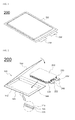
- FIG. 1 is a schematic perspective view of an exemplary battery cell mounted in a unit module according to the present invention
- FIG. 2 is a schematic exploded view of FIG. 1 .
- a pouch-shaped battery cell 200 has a structure in which an electrode assembly 210, including cathodes, anodes and separators disposed between the cathodes and the anodes, is sealed in a pouch-shaped battery case 100 such that two electrode terminals 222 and 232 electrically connected to cathode and anode tabs 220 and 230 of the electrode assembly are exposed to the outside.
- the battery case 100 includes a case body 140 having a recessed receiving part 142, in which the electrode assembly 210 can be placed, and a cover 150 integrally connected to the case body 140.
- the cathode tabs 220 and the anode tabs 230 of the electrode assembly 210 which has a stacked structure or a stacked/folded structure, are coupled respectively to the electrode terminal 222 and the electrode terminal 232 by welding.
- the electrode assembly 210 may also have a structure, such as a folded structure, rather than the stacked or stacked/folded structure.
- Insulating films 240 are also attached to the top and bottom of each of the electrode terminals 222 and 232 to prevent the occurrence of a short circuit between a thermal welder and the electrode terminals 222 and 232 and to achieve sealing between the electrode terminals 222 and 232 and the battery case 100 when a surplus part 144 of the case body 140 and the cover 150 are thermally welded to each other using the thermal welder.
- Each of the case body 140 and the cover 150 includes an outer resin layer 110, an isolation metal layer 120, and an inner resin layer 130.
- the inner resin layers 130 of the case body 140 and the cover 150 may be tightly fixed to the each other by heat and pressure that the thermal welder (not shown) applies to the outer surfaces of the case body 140 and the cover 150.
- FIG. 3 is a schematic perspective view of a battery module to which a voltage sensing assembly according to an embodiment of the present invention is mounted
- FIG. 4 is a schematic magnified perspective view of a part A of the battery module of FIG. 3
- FIG. 5 is a schematic magnified perspective view of a part B of FIG. 4 .
- a voltage sensing assembly 300 includes a block case 310 formed of an electrically insulating material, wires 320 connected respectively to voltage sensing terminals, and a connector 330 that transmits detected voltages of the wires 320 to a controller (not shown).
- the block case 310 is mounted, horizontally within a space between electrode terminal connection parts of battery cells, to the front of the battery module 800.
- Voltage sensing terminals 342 and 346 are formed at upper or lower ends of bus bars 340 electrically connected to the electrode terminal connection parts of the battery cells.
- a clamp-shaped fastening member 312 protrudes forward from the block case 310 to securely fix the wires 320.
- the wires 320 are connected to the voltage sensing terminals 346 of the bus bars 340 in a state in which the wires 320 are mounted to the fastening member 312 of the block case 310.
- the block case 310 is provided at upper and lower ends thereof with openings 314 at positions corresponding to the voltage sensing terminals 342 of the bus bars 340 such that the voltage sensing terminals 342 are inserted into the openings 314.
- Each of the voltage sensing terminals 342 has a clamping structure into which a wire 320 is inserted.
- the wires 320 are mounted in a plate-shaped insulating member 322 to achieve insulation from the outside.
- Each of the bus bars 340 includes a plate-shaped body 344 and a voltage sensing terminal 342.
- the plate-shaped body 344 is bent perpendicularly at opposite lateral ends thereof such that the plate-shaped body 344 is electrically connected to electrode terminal connection parts of corresponding battery cells.
- the voltage sensing terminal 342 is integrally formed at an upper or lower end of the plate-shaped body 344.
- a bus bar which is connected to each of a cathode external input and output terminal 402 and an anode external input and output terminal 404, includes an external input and output terminal connection part 348 which extends diagonally downward from one side of the lower end of a plate-shaped body 344 of the bus bar.
- the external input and output terminal connection part 348 has a fastening hole 349 such that the external input and output terminal 404 is inserted into the fastening hole 349 to achieve electrical connection between the bus bar and the external input and output terminal 404.
- Voltage sensing terminals 346 of the bus bars connected to the cathode external input and output terminal 402 and the anode external input and output terminal 404 are formed at lower ends of the bus bars which are perpendicularly bent forward of the battery module 800.
- Partition walls 316 are formed at upper and lower end surfaces of the block case 310 to prevent current passage through moisture.
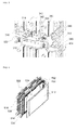
- FIG. 6 is a schematic exploded view of a unit module according to another embodiment of the present invention and FIG. 7 is a schematic perspective view of the unit module of FIG. 6 when assembled.
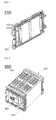
- FIG. 8 is a schematic perspective view of the battery module of FIG. 3 with a cover attached to the front of the battery module and
- FIG. 9 is a schematic perspective view of the cover of FIG. 8 .
- a battery module 900 includes a voltage sensing assembly 300, two unit module stacks 500, cover members 600 attached to four corners of the unit module stacks 500, and a cover 610 attached to the front of the battery module.
- Each of the unit module stacks 500 includes four unit modules 510 which are arranged side by side, each of the unit modules being structured such that three battery cells 512, 514, and 516, which are housed within two cell covers 520 and 522, are mounted in two cartridges 530 and 532.
- Each of the cartridges 530 has a rectangular structure corresponding to a battery cell such that battery cells can be mounted in the cartridge 530.
- Each of the cartridges 530 is provided at a central region thereof with a through hole 534 for heat dissipation.
- Fastening holes 536 through which fastening members (not shown) are inserted to fasten the unit modules 510, are formed in four corners of the cartridge 530.
- the cartridge 530 is also provided at the front thereof with a coupling part 538, to which an insulative mounting member 700 for mounting the voltage sensing assembly 300 and the bus bars is fastened in an assembly fashion such that the voltage sensing assembly 300 is securely connected to the bus bars.
- the cover 610 has a size corresponding to the front of the battery module 900 and is formed of injection-molded plastic. Marks 612 and 614 indicating the polarities of the cathode external input and output terminal 402 and the anode external input and output terminal 404 are printed on the surface of the cover 610 at opposite lateral sides thereof.
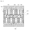
- FIG. 10 is a schematic magnified view of a part of the front of the battery module of FIG. 3 and FIG. 11 is a schematic perspective view of the insulative mounting member in the battery module of FIG. 3 .
- FIG. 12 is a schematic magnified view of a part C of FIG. 11 .
- the insulative mounting member 700 has a rectangular parallelepiped structure having a size corresponding to the front of the unit module stack 500.
- the insulative mounting member 700 is provided at the rear thereof with cartridge coupling grooves (not shown) into which the front ends of the cartridges are inserted and coupled.
- the insulative mounting member 700 is also provided at the front thereof with electrode terminal through holes 710, through which the electrode terminal connection parts 524 of the battery cells are introduced from the rear of the insulative mounting member 700 such that the electrode terminal connection parts 524 are exposed.
- location parts 720 for external input and output terminal connection parts are formed on the front of the insulative mounting member 700 at opposite ends thereof to securely mount the external input and output terminal connection parts 348 of the bus bars 340 to the insulative mounting member 700.
- a block case location part 730 is formed on the front of the insulative mounting member 700 at a central region thereof to securely mount the block case 310 to the insulative mounting member 700.
- Bus bar location parts 740 are formed on the front of the insulative mounting member 700 to mount the bus bars 340 to the insulative mounting member 700.
- a fastening protrusion 722 is formed on each of the location parts 720 for external input and output terminal connection parts.
- the electrode terminal connection parts 524 of the battery cells, which are exposed forward through the electrode terminal through holes 710, are electrically connected to opposite lateral sides of the bus bars 340 which are mounted in the electrode terminal through holes 710.
- Protrusions 742 for fixing the bus bars which project from the bus bar location parts 740, are coupled to the bus bars 340 through thermal welding and partition walls 750 and 752 are formed on upper and lower end surfaces of the insulative mounting member 700 to prevent current passage through moisture and short circuit through condensation.
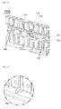
- FIG. 13 is a schematic perspective view of a voltage sensing assembly according to another embodiment of the present invention and FIG. 14 is a schematic magnified view of a part D of FIG. 13 .
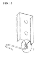
- FIG. 15 is a schematic magnified view of a part E of FIG. 13 .
- a voltage sensing assembly 300a includes bus bars 340 electrically connected to electrode terminal connection parts of battery cells, wires 320 connected respectively to voltage sensing terminals 342, each of which is integrally formed at an upper or lower end of a corresponding one of the bus bars 340, and a connector 330 that transmits detected voltages of the wires 320 to a controller.
- the voltage sensing terminals 342 have a clamping structure F, into which the wires 320 are inserted, such that the wires 320 are securely fixed to the voltage sensing terminals 342.
- a wire 324 for detecting voltage of an external input and output terminal is coupled to a bus bar 341 connected to the external input and output terminal through a rivet structure D.
- a voltage sensing assembly according to the present invention can achieve a reliable sensing structure since wires are directly assembled on bus bars without using additional assembly structures such as connection structures between bus bars and receptacle terminals.
- the voltage sensing assembly according to the present invention is manufactured through a simple assembly method without using a number of members for mechanical coupling and electrical connection. Therefore, it is possible to reduce manufacturing costs of the voltage sensing assembly and also to reliably measure voltage even when strong external impact or vibration is applied to the voltage sensing assembly.
- the voltage sensing assembly according to the present invention is formed as a separate assembly.
Abstract
Description
- The present invention relates to a voltage sensing assembly for sensing voltage of battery cells, each having electrode terminals formed at an upper or lower end thereof, in a state in which the voltage sensing assembly is mounted to a battery module, the voltage sensing assembly including a block case, which is formed of an electrically insulating material and is mounted, horizontally within a space between electrode terminal connection parts of the battery cells, to the front or rear of the battery module, wires connected respectively to voltage sensing terminals, each of the voltage sensing terminals being integrally formed at an upper or lower end of a corresponding one of bus bars, and a connector that transmits detected voltages of the wires to a controller, wherein the block case includes a fastening member that protrudes forward from the block case to securely fix the wires, and the wires are connected to the voltage sensing terminals of the bus bars in a state in which the wires are mounted to the fastening member of the block case.
- Recently, secondary batteries, which can be charged and discharged, have been widely used as energy sources for wireless mobile devices. Secondary batteries have also attracted considerable attention as power sources for electric vehicles (EV), hybrid electric vehicles (HEV) and plug-in hybrid electric vehicles (plug-in HEV), which have been developed to solve problems, such as air pollution, caused by existing gasoline and diesel vehicles that use fossil fuels.
- Small-sized mobile devices use one or several battery cells for each device. On the other hand, middle or large-sized devices such as vehicles use a battery module including a number of battery cells electrically connected to each other because high power and large capacity are necessary for the middle or large-sized devices.
- Since the battery module is preferably manufactured to have as small a size and weight as possible, prismatic batteries or pouch-shaped batteries, which can be stacked with high integration and have a small weight to capacity ratio, are usually used as battery cells of middle or large-sized battery modules. In particular, much interest is currently focused on pouch-shaped batteries, which use an aluminum laminate sheet as a sheathing member, due to their advantages of being lightweight and cheap to manufacture.
- In addition, since the battery module is made up by combining a number of battery cells, safety and operating efficiency of the battery module are considerably deteriorated when some of the battery cells suffer from overvoltage, overcurrent or overheat. Therefore, it is necessary to provide a means for sensing and controlling such overvoltage, overcurrent or overheat. Thus, voltage sensors or the like are connected to the battery cells to check and control operating states of the battery cells in real time or at predetermined intervals. However, installation or connection of such measuring members greatly complicates the process of assembling the battery module and may cause a short circuit due to use of many wires. Further, as the secondary battery is used as a power source for vehicles as a result of extension of the application range of the secondary battery, there is a need to provide a fastening means to maintain the sensing means in a stable contact state even when strong impact or vibration is applied to the battery module.
- In addition, when a battery module is constructed using a plurality of battery cells or is constructed using a plurality of cell modules, each including a specific number of battery cells, it is generally necessary to provide a large number of members for mechanical coupling and electrical connection between the battery cells or the unit modules and therefore the process of assembling such members is very complicated.
- Furthermore, spaces for coupling, welding, or soldering of the members are needed to achieve such mechanical coupling and electrical connection, thereby increasing overall battery system size. Such size increase is undesirable as previously described.
- In addition, when additional assembly parts such as receptacle terminals are used, there is a problem in that correct voltage sensing is not easy due to contact resistance at contact portions of the assembly parts.
- Thus, there is a great need to provide a voltage sensing assembly, which is more compact and exhibits improved voltage sensing reliability while fundamentally solving the above problems, and a battery module including the same.
- Therefore, the present invention has been made to solve the above and other technical problems that have yet to be resolved.
- Specifically, it is an object of the present invention to provide a voltage sensing assembly structured such that wires are directly assembled on bus bars without using additional assembly structures such as connection structures between bus bars and receptacle terminals to achieve a reliable sensing structure.
- It is another object to provide a voltage sensing assembly that can be manufactured through a simple assembly method without using a number of members for mechanical coupling and electrical connection.
- It is another object to provide a voltage sensing assembly that is formed as a separate assembly to improve productivity and maintenance of battery modules.
- In accordance with the present invention, the above and other objects can be accomplished by the provision of a voltage sensing assembly for sensing voltage of battery cells, each having electrode terminals formed at an upper or lower end thereof, in a state in which the voltage sensing assembly is mounted to a battery module, the voltage sensing assembly including (a) a block case formed of an electrically insulating material, the block case being mounted, horizontally within a space between electrode terminal connection parts of the battery cells, to the front or rear of the battery module, (b) wires connected respectively to voltage sensing terminals, each of the voltage sensing terminals being integrally formed at an upper or lower end of a corresponding one of bus bars electrically connected to the electrode terminal connection parts of the battery cells, and (c) a connector that transmits detected voltages of the wires to a controller, wherein the block case includes a fastening member that protrudes forward from the block case to securely fix the wires, and the wires are connected to the voltage sensing terminals of the bus bars in a state in which the wires are mounted to the fastening member of the block case.
- In the voltage sensing assembly according to the present invention, the wires are connected to the voltage sensing terminals of the bus bars in a state in which the wires are mounted to the fastening member of the block case. Therefore, the voltage sensing assembly has a compact structure to reliably measure voltage and the overall assembly process thereof is simple.
- In addition, it is possible to reduce the number of parts, decreasing production costs, since the wires are connected to the voltage sensing terminals of the bus bars without additional assembly parts such as receptacle terminals and it is possible to improve the reliability of voltage sensing since there is no contact resistance of the assembly parts.
- Further, the voltage sensing assembly can easily be mounted to the front or rear of the battery module since the voltage sensing assembly for sensing voltage of battery cells has a single modular assembly structure.
- Furthermore, the assembly structure of the voltage sensing assembly, which is configured as a separate unit, allows manufacture of the voltage sensing assembly to be outsourced, thereby greatly improving productivity of battery modules. When parts of the voltage sensing assembly malfunction, the voltage sensing assembly mounted to the front or rear of the battery module can be replaced without disassembly of the battery module, thereby greatly improving maintenance as compared with the conventional battery module structure.
- For example, the controller may be a Battery Management System (BMS).
- Preferably, the block case is provided at upper and lower ends thereof with openings at positions corresponding to the voltage sensing terminals of the bus bars such that the voltage sensing terminals are inserted into the openings. This makes it possible to prevent the voltage sensing terminals from protruding from the front of the block case.
- Although the structure of the voltage sensing terminals is not particularly limited so long as the voltage sensing terminals are easily coupled to wires, each of the voltage sensing terminals may have, for example, a clamping structure into which a wire is inserted. This makes it possible to easily achieve coupling between the wires and the voltage sensing terminals through simple manipulation.
- Preferably, each of the wires is wrapped with an insulating tape or is mounted in a tubular insulating member to achieve insulation from the outside. The tubular insulating member may be, for example, a hollow insulating pipe.
- Although the shape of the fastening member is not particularly limited so long as wires are easily mounted to the fastening member, the fastening member may be, for example, clamp-shaped. This makes it possible to easily mount wires and to prevent the mounted wires from being dislocated.
- In a preferred example, each of the bus bars may include a plate-shaped body, which is bent perpendicularly at opposite lateral ends thereof such that the plate-shaped body is electrically connected to electrode terminal connection parts of corresponding battery cells, and a voltage sensing terminal formed at an upper or lower end of the plate-shaped body.
- In a specific example, one of the bus bars, which is connected to a cathode or anode external input and output terminal, may further include an external input and output terminal connection part that extends diagonally downward from one side of a lower end of a plate-shaped body of the one bus bar.
- In this structure, the external input and output terminal connection part is provided with a fastening hole into which the external input and output terminal can be coupled. Thus, the external input and output terminal is inserted into the fastening hole of the external input and output terminal connection part to achieve electrical connection of the bus bar with the external input and output terminal.
- In a preferred example, a voltage sensing terminal of one of the bus bars connected to a cathode or anode external input and output terminal may be formed at a lower end of the one bus bar, the lower end being perpendicularly bent forward of the battery module.
- Preferably, partition walls for preventing current passage through moisture are formed on upper and lower end surfaces of the block case. This prevents current passage through moisture.
- The present invention provides a battery module including the voltage sensing assembly.
- In a preferred example, the battery module includes a unit module stack in which two or more unit modules are arranged side by side, each of the unit modules being structured such that one or more battery cells housed within a cell cover are mounted in a cartridge, and cover members attached to four corners of the unit module stack.
- In a preferred example, each of the cartridges has a rectangular structure corresponding to a battery cell such that the battery cell can be mounted in the cartridge and is provided at a central region thereof with a through hole for heat dissipation, fastening holes, through which fastening members to fix the unit module stack are inserted, are formed in four corners of each of the cartridges, and a coupling part, to which an insulative mounting member for mounting the voltage sensing assembly and bus bars is fastened in an assembly fashion such that the voltage sensing assembly is securely connected to the bus bars, is formed at the front of each of the cartridges.
- For example, the bus bars may be thermally welded to an injection molded material of the insulative mounting member.
- The insulative mounting member may have a rectangular parallelepiped structure having a size corresponding to the front of the unit module stack and may be provided at the rear thereof with cartridge coupling grooves, into which front ends of the cartridges can be inserted and coupled, and at opposite sides of the front thereof with electrode terminal through holes, through which electrode terminal connection parts of the battery cells are introduced from the rear of the insulative mounting member such that the electrode terminal connection parts are exposed.
- In an example, the insulative mounting member may be provided at opposite ends of the front thereof with external input and output terminal connection part location parts to securely mount external input and output terminal connection parts of the bus bars to the insulative mounting member, at a central region of the front thereof with a block case location part to securely mount the block case to the insulative mounting member, and on the front thereof with bus bar location parts, each having a size corresponding to each of the bus bars, to mount the bus bars to the insulative mounting member.
- A fastening protrusion may be formed on each of the external input and output terminal connection part location parts. Thus, the fastening protrusion can easily be inserted into a corresponding one of the external input and output terminal connection parts of the bus bars.
- The electrode terminal connection parts of the battery cells, which are exposed forward through the electrode terminal through holes, may be electrically connected to opposite lateral sides of the bus bars, the opposite lateral sides being mounted in the electrode terminal through holes.
- Preferably, the bus bars are coupled to the bus bar location parts through thermal welding. Thus, the bus bars and the insulative mounting member may be integrally formed.
- Partition walls may be formed on upper and lower end surfaces of the insulative mounting member to prevent current passage through moisture.
- Each of the battery cells may be a pouch-shaped battery cell including an electrode assembly mounted in a case formed of a laminate sheet including a resin layer and a metal layer.
- The battery module according to the present invention generally has an overall compact structure and can achieve structurally stable mechanical fastening and electrical connection without using a large number of members. A predetermined number, such as 4, 6, 8, or 10, of battery cells or cell modules may constitute a battery module and therefore it is possible to effectively mount a necessary number of battery modules in a limited space.
- The present invention also provides a high-power, large-capacity battery pack manufactured using the battery module as a unit body.
- The battery pack according to the present invention may be manufactured by combining battery modules based on desired power and capacity. In consideration of installation efficiency and structural stability as previously described, the battery pack according to the present invention is preferably used as a power source for electric vehicles, hybrid electric vehicles, plug-in hybrid electric vehicles, or power storage devices.
- The present invention also provides a voltage sensing assembly having a different structure.
- Specifically, the present invention provides a voltage sensing assembly for sensing voltage of battery cells, each having electrode terminals formed at an upper or lower end thereof, in a state in which the voltage sensing assembly is mounted to a battery module, the voltage sensing assembly including (a) bus bars electrically connected to electrode terminal connection parts of the battery cells, (b) wires connected respectively to voltage sensing terminals, each of the voltage sensing terminals being integrally formed at an upper or lower end of a corresponding one of the bus bars, and (c) a connector that transmits detected voltages of the wires to a controller, wherein each of the voltage sensing terminals has a clamping structure into which a wire is inserted.
- In the voltage sensing assembly, each of the voltage sensing terminals has a clamping structure to which a wire can be fastened and is integrally formed at an upper or lower end of a corresponding one of the bus bars. Therefore, it is possible to reliably sense voltage of the battery module without additional receptacle terminals.
- The above and other objects, features and other advantages of the present invention will be more clearly understood from the following detailed description taken in conjunction with the accompanying drawings, in which:
-
FIG. 1 is a schematic perspective view of a battery cell mounted in a unit module; -
FIG. 2 is a schematic exploded view ofFIG. 1 ; -
FIG. 3 is a perspective view of a battery module to which a voltage sensing assembly according to an embodiment of the present invention is mounted; -
FIG. 4 is a magnified perspective view of a part A of the battery module ofFIG. 3 ; -
FIG. 5 is a magnified perspective view of a part B ofFIG. 4 ; -
FIG. 6 is an exploded view of a unit module according to another embodiment of the present invention; -
FIG. 7 is a perspective view of the unit module ofFIG. 6 when assembled; -
FIG. 8 is a perspective view of the battery module ofFIG. 3 with a cover attached to the front of the battery module; -
FIG. 9 is a perspective view of the cover ofFIG. 8 ; -
FIG. 10 is a magnified view of a part of the front of the battery module ofFIG. 3 ; -
FIG. 11 is a perspective view of the insulative mounting member in the battery module ofFIG. 3 ; -
FIG. 12 is a schematic magnified view of a part C ofFIG. 11 ; -
FIG. 13 is a perspective view of a voltage sensing assembly according to another embodiment of the present invention; -
FIG. 14 is a schematic magnified view of a part D ofFIG. 13 ; and -
FIG. 15 is a schematic magnified view of a part E ofFIG. 13 . - Now, embodiments of the present invention will be described in detail with reference to the accompanying drawings. However, it should be noted that the description of the embodiments is given to provide better understanding of the present invention without limiting the scope of the invention.
-
FIG. 1 is a schematic perspective view of an exemplary battery cell mounted in a unit module according to the present invention, andFIG. 2 is a schematic exploded view ofFIG. 1 . - As shown in
FIGS. 1 and 2 , a pouch-shapedbattery cell 200 has a structure in which anelectrode assembly 210, including cathodes, anodes and separators disposed between the cathodes and the anodes, is sealed in a pouch-shapedbattery case 100 such that twoelectrode terminals anode tabs - The
battery case 100 includes acase body 140 having a recessed receivingpart 142, in which theelectrode assembly 210 can be placed, and acover 150 integrally connected to thecase body 140. - The
cathode tabs 220 and theanode tabs 230 of theelectrode assembly 210, which has a stacked structure or a stacked/folded structure, are coupled respectively to theelectrode terminal 222 and theelectrode terminal 232 by welding. Here, theelectrode assembly 210 may also have a structure, such as a folded structure, rather than the stacked or stacked/folded structure. - Insulating
films 240 are also attached to the top and bottom of each of theelectrode terminals electrode terminals electrode terminals battery case 100 when asurplus part 144 of thecase body 140 and thecover 150 are thermally welded to each other using the thermal welder. - Each of the
case body 140 and thecover 150 includes anouter resin layer 110, anisolation metal layer 120, and aninner resin layer 130. The inner resin layers 130 of thecase body 140 and thecover 150 may be tightly fixed to the each other by heat and pressure that the thermal welder (not shown) applies to the outer surfaces of thecase body 140 and thecover 150. - In a state in which the
electrode assembly 210 impregnated with an electrolyte is placed in the receivingpart 142, contact parts between thesurplus part 144 of thecase body 140 and thecover 150 are thermally welded to form sealed parts. -
FIG. 3 is a schematic perspective view of a battery module to which a voltage sensing assembly according to an embodiment of the present invention is mounted,FIG. 4 is a schematic magnified perspective view of a part A of the battery module ofFIG. 3 , andFIG. 5 is a schematic magnified perspective view of a part B ofFIG. 4 . - As shown in these drawings, a
voltage sensing assembly 300 includes ablock case 310 formed of an electrically insulating material,wires 320 connected respectively to voltage sensing terminals, and aconnector 330 that transmits detected voltages of thewires 320 to a controller (not shown). - The
block case 310 is mounted, horizontally within a space between electrode terminal connection parts of battery cells, to the front of thebattery module 800.Voltage sensing terminals bus bars 340 electrically connected to the electrode terminal connection parts of the battery cells. - A clamp-shaped
fastening member 312 protrudes forward from theblock case 310 to securely fix thewires 320. Thewires 320 are connected to thevoltage sensing terminals 346 of the bus bars 340 in a state in which thewires 320 are mounted to thefastening member 312 of theblock case 310. - The
block case 310 is provided at upper and lower ends thereof withopenings 314 at positions corresponding to thevoltage sensing terminals 342 of the bus bars 340 such that thevoltage sensing terminals 342 are inserted into theopenings 314. Each of thevoltage sensing terminals 342 has a clamping structure into which awire 320 is inserted. - The
wires 320 are mounted in a plate-shaped insulatingmember 322 to achieve insulation from the outside. Each of the bus bars 340 includes a plate-shapedbody 344 and avoltage sensing terminal 342. - The plate-shaped
body 344 is bent perpendicularly at opposite lateral ends thereof such that the plate-shapedbody 344 is electrically connected to electrode terminal connection parts of corresponding battery cells. Thevoltage sensing terminal 342 is integrally formed at an upper or lower end of the plate-shapedbody 344. - A bus bar, which is connected to each of a cathode external input and
output terminal 402 and an anode external input andoutput terminal 404, includes an external input and outputterminal connection part 348 which extends diagonally downward from one side of the lower end of a plate-shapedbody 344 of the bus bar. - The external input and output
terminal connection part 348 has afastening hole 349 such that the external input andoutput terminal 404 is inserted into thefastening hole 349 to achieve electrical connection between the bus bar and the external input andoutput terminal 404. -
Voltage sensing terminals 346 of the bus bars connected to the cathode external input andoutput terminal 402 and the anode external input andoutput terminal 404 are formed at lower ends of the bus bars which are perpendicularly bent forward of thebattery module 800.Partition walls 316 are formed at upper and lower end surfaces of theblock case 310 to prevent current passage through moisture. -
FIG. 6 is a schematic exploded view of a unit module according to another embodiment of the present invention andFIG. 7 is a schematic perspective view of the unit module ofFIG. 6 when assembled. -
FIG. 8 is a schematic perspective view of the battery module ofFIG. 3 with a cover attached to the front of the battery module andFIG. 9 is a schematic perspective view of the cover ofFIG. 8 . - Referring to
FIGS. 8 and9 , together withFIGS. 1 to 4 , abattery module 900 includes avoltage sensing assembly 300, two unit module stacks 500,cover members 600 attached to four corners of the unit module stacks 500, and acover 610 attached to the front of the battery module. - Each of the unit module stacks 500 includes four
unit modules 510 which are arranged side by side, each of the unit modules being structured such that threebattery cells cartridges - Each of the
cartridges 530 has a rectangular structure corresponding to a battery cell such that battery cells can be mounted in thecartridge 530. Each of thecartridges 530 is provided at a central region thereof with a throughhole 534 for heat dissipation. Fastening holes 536, through which fastening members (not shown) are inserted to fasten theunit modules 510, are formed in four corners of thecartridge 530. - The
cartridge 530 is also provided at the front thereof with acoupling part 538, to which aninsulative mounting member 700 for mounting thevoltage sensing assembly 300 and the bus bars is fastened in an assembly fashion such that thevoltage sensing assembly 300 is securely connected to the bus bars. - The
cover 610 has a size corresponding to the front of thebattery module 900 and is formed of injection-molded plastic.Marks output terminal 402 and the anode external input andoutput terminal 404 are printed on the surface of thecover 610 at opposite lateral sides thereof. -
FIG. 10 is a schematic magnified view of a part of the front of the battery module ofFIG. 3 andFIG. 11 is a schematic perspective view of the insulative mounting member in the battery module ofFIG. 3 . -
FIG. 12 is a schematic magnified view of a part C ofFIG. 11 . - Referring to
FIGS. 10 to 12 , together withFIGS. 4 to 7 , theinsulative mounting member 700 has a rectangular parallelepiped structure having a size corresponding to the front of theunit module stack 500. Theinsulative mounting member 700 is provided at the rear thereof with cartridge coupling grooves (not shown) into which the front ends of the cartridges are inserted and coupled. Theinsulative mounting member 700 is also provided at the front thereof with electrode terminal throughholes 710, through which the electrodeterminal connection parts 524 of the battery cells are introduced from the rear of theinsulative mounting member 700 such that the electrodeterminal connection parts 524 are exposed. - In addition,
location parts 720 for external input and output terminal connection parts are formed on the front of theinsulative mounting member 700 at opposite ends thereof to securely mount the external input and outputterminal connection parts 348 of the bus bars 340 to theinsulative mounting member 700. A blockcase location part 730 is formed on the front of theinsulative mounting member 700 at a central region thereof to securely mount theblock case 310 to theinsulative mounting member 700. - Bus
bar location parts 740, each having a size corresponding to abus bar 340, are formed on the front of theinsulative mounting member 700 to mount the bus bars 340 to theinsulative mounting member 700. - A
fastening protrusion 722 is formed on each of thelocation parts 720 for external input and output terminal connection parts. The electrodeterminal connection parts 524 of the battery cells, which are exposed forward through the electrode terminal throughholes 710, are electrically connected to opposite lateral sides of the bus bars 340 which are mounted in the electrode terminal throughholes 710. -
Protrusions 742 for fixing the bus bars, which project from the busbar location parts 740, are coupled to the bus bars 340 through thermal welding andpartition walls insulative mounting member 700 to prevent current passage through moisture and short circuit through condensation. -
FIG. 13 is a schematic perspective view of a voltage sensing assembly according to another embodiment of the present invention andFIG. 14 is a schematic magnified view of a part D ofFIG. 13 . -
FIG. 15 is a schematic magnified view of a part E ofFIG. 13 . - As shown in
FIGS. 13 to 15 , avoltage sensing assembly 300a includes bus bars 340 electrically connected to electrode terminal connection parts of battery cells,wires 320 connected respectively tovoltage sensing terminals 342, each of which is integrally formed at an upper or lower end of a corresponding one of the bus bars 340, and aconnector 330 that transmits detected voltages of thewires 320 to a controller. - The
voltage sensing terminals 342 have a clamping structure F, into which thewires 320 are inserted, such that thewires 320 are securely fixed to thevoltage sensing terminals 342. - A
wire 324 for detecting voltage of an external input and output terminal is coupled to abus bar 341 connected to the external input and output terminal through a rivet structure D. - Although the present invention has been described above with reference to the drawings which illustrate the embodiments of the present invention, it will be apparent to those skilled in the art that various modifications and variations are possible in light of the above teaching without departing from the scope of the invention.
- As is apparent from the above description, a voltage sensing assembly according to the present invention can achieve a reliable sensing structure since wires are directly assembled on bus bars without using additional assembly structures such as connection structures between bus bars and receptacle terminals.
- In addition, the voltage sensing assembly according to the present invention is manufactured through a simple assembly method without using a number of members for mechanical coupling and electrical connection. Therefore, it is possible to reduce manufacturing costs of the voltage sensing assembly and also to reliably measure voltage even when strong external impact or vibration is applied to the voltage sensing assembly.
- Further, it is possible to greatly improve productivity and maintenance of battery modules since the voltage sensing assembly according to the present invention is formed as a separate assembly.
Claims (22)
- A voltage sensing assembly for sensing voltage of battery cells, each having electrode terminals formed at an upper or lower end thereof, in a state in which the voltage sensing assembly is mounted to a battery module, the voltage sensing assembly comprising:(a) a block case formed of an electrically insulating material, the block case being mounted, horizontally within a space between electrode terminal connection parts of the battery cells, to the front or rear of the battery module;(b) wires connected respectively to voltage sensing terminals, each of the voltage sensing terminals being integrally formed at an upper or lower end of a corresponding one of bus bars electrically connected to the electrode terminal connection parts of the battery cells; and(c) a connector that transmits detected voltages of the wires to a controller,
wherein the block case comprises a fastening member that protrudes forward from the block case to securely fix the wires, and
the wires are connected to the voltage sensing terminals of the bus bars in a state in which the wires are mounted to the fastening member of the block case. - The voltage sensing assembly according to claim 1, wherein the block case is provided at upper and lower ends thereof with openings at positions corresponding to the voltage sensing terminals of the bus bars such that the voltage sensing terminals are inserted into the openings.
- The voltage sensing assembly according to claim 1, wherein each of the voltage sensing terminals has a clamping structure into which a wire is inserted.
- The voltage sensing assembly according to claim 1, wherein each of the wires is wrapped with an insulating tape or is mounted in a tubular insulating member to achieve insulation from the outside.
- The voltage sensing assembly according to claim 1, wherein the fastening member is clamp-shaped.
- The voltage sensing assembly according to claim 1, wherein each of the bus bars comprises a plate-shaped body, which is bent perpendicularly at opposite lateral ends thereof such that the plate-shaped body is electrically connected to electrode terminal connection parts of corresponding battery cells, and a voltage sensing terminal formed at an upper or lower end of the plate-shaped body.
- The voltage sensing assembly according to claim 6, wherein one of the bus bars, which is connected to a cathode or anode external input and output terminal, further comprises an external input and output terminal connection part that extends diagonally downward from one side of a lower end of a plate-shaped body of the one bus bar.
- The voltage sensing assembly according to claim 7, wherein the external input and output terminal connection part is provided with a fastening hole into which the external input and output terminal can be coupled.
- The voltage sensing assembly according to claim 6, wherein a voltage sensing terminal of one of the bus bars connected to the cathode or anode external input and output terminal is formed at a lower end of the one bus bar, the lower end thereof being perpendicularly bent forward of the battery module.
- The voltage sensing assembly according to claim 1, wherein partition walls are formed on upper and lower end surfaces of the block case to prevent current passage through moisture.
- A battery module comprising:a voltage sensing assembly according to claim 1;a unit module stack in which two or more unit modules are arranged side by side, each of the unit modules being structured such that one or more battery cells housed within a cell cover are mounted in a cartridge; andcover members attached to four corners of the unit module stack.
- The battery module according to claim 11, wherein each of the cartridges has a rectangular structure corresponding to a battery cell such that the battery cell can be mounted in the cartridge and is provided at a central region thereof with a through hole for heat dissipation,
fastening holes, through which fastening members to fix the unit module stack are inserted, are formed in four corners of each of the cartridges, and
a coupling part, to which an insulative mounting member for mounting the voltage sensing assembly and bus bars is fastened in an assembly fashion such that the voltage sensing assembly is securely connected to the bus bars, is formed at the front of each of the cartridges. - The battery module according to claim 12, wherein the insulative mounting member has a rectangular parallelepiped structure having a size corresponding to the front of the unit module stack and is provided at the rear thereof with cartridge coupling grooves, into which front ends of the cartridges can be inserted and coupled, and at the front thereof with electrode terminal through holes, through which electrode terminal connection parts of the battery cells are introduced from the rear of the insulative mounting member such that the electrode terminal connection parts are exposed.
- The battery module according to claim 13, wherein the insulative mounting member is provided at opposite ends of the front thereof with external input and output terminal connection part location parts to securely mount external input and output terminal connection parts of the bus bars to the insulative mounting member, at a central region of the front thereof with a block case location part to securely mount the block case to the insulative mounting member, and on the front thereof with bus bar location parts, each having a size corresponding to each of the bus bars, to mount the bus bars to the insulative mounting member.
- The battery module according to claim 14, wherein a fastening protrusion is formed on each of the external input and output terminal connection part location parts.
- The battery module according to claim 14, wherein the electrode terminal connection parts of the battery cells, which are exposed forward through the electrode terminal through holes, are electrically connected to opposite lateral sides of the bus bars, the opposite lateral sides being mounted in the electrode terminal through holes.
- The battery module according to claim 14, wherein the bus bars are coupled to the bus bar location parts through thermal welding.
- The battery module according to claim 13, wherein partition walls are formed on upper and lower end surfaces of the insulative mounting member to prevent current passage through moisture.
- The battery module according to claim 11, wherein each of the battery cells is a pouch-shaped battery cell including an electrode assembly mounted in a case formed of a laminate sheet comprising a resin layer and a metal layer.
- A high-power, large-capacity battery pack manufactured using a battery module according to claim 11 as a unit body.
- The battery module according to claim 20, wherein the battery pack is used as a power source for electric vehicles, hybrid electric vehicles, plug-in hybrid electric vehicles, or power storage devices.
- A voltage sensing assembly for sensing voltage of battery cells, each having electrode terminals formed at an upper or lower end thereof, in a state in which the voltage sensing assembly is mounted to a battery module, the voltage sensing assembly comprising:(a) bus bars electrically connected to electrode terminal connection parts of the battery cells;(b) wires connected respectively to voltage sensing terminals, each of the voltage sensing terminals being integrally formed at an upper or lower end of a corresponding one of the bus bars; and(c) a connector that transmits detected voltages of the wires to a controller,
wherein each of the voltage sensing terminals has a clamping structure into which a wire is inserted.
Applications Claiming Priority (2)
| Application Number | Priority Date | Filing Date | Title |
|---|---|---|---|
| KR1020110045010A KR101276186B1 (en) | 2011-05-13 | 2011-05-13 | Voltage Sensing Assembly and Battery Module Employed with the Same |
| PCT/KR2012/003145 WO2012157856A2 (en) | 2011-05-13 | 2012-04-24 | Voltage sensing assembly and battery module having same |
Publications (3)
| Publication Number | Publication Date |
|---|---|
| EP2672284A2 true EP2672284A2 (en) | 2013-12-11 |
| EP2672284A4 EP2672284A4 (en) | 2014-09-24 |
| EP2672284B1 EP2672284B1 (en) | 2018-08-08 |
Family
ID=47177421
Family Applications (1)
| Application Number | Title | Priority Date | Filing Date |
|---|---|---|---|
| EP12785388.5A Active EP2672284B1 (en) | 2011-05-13 | 2012-04-24 | Voltage sensing assembly and battery module having same |
Country Status (6)
| Country | Link |
|---|---|
| US (1) | US9097771B2 (en) |
| EP (1) | EP2672284B1 (en) |
| JP (1) | JP5912171B2 (en) |
| KR (1) | KR101276186B1 (en) |
| CN (1) | CN103492892B (en) |
| WO (1) | WO2012157856A2 (en) |
Cited By (3)
| Publication number | Priority date | Publication date | Assignee | Title |
|---|---|---|---|---|
| EP2989676B1 (en) | 2013-04-23 | 2017-03-01 | ElringKlinger AG | Cell contacting system for an electrochemical device |
| EP3240098A4 (en) * | 2014-12-22 | 2017-11-01 | Autonetworks Technologies, Ltd. | Electricity storage pack |
| CN108140867A (en) * | 2015-10-22 | 2018-06-08 | 株式会社Lg化学 | Pouch-type battery cell with the cell electrode for being formed with multiple electrodes contact pin |
Families Citing this family (23)
| Publication number | Priority date | Publication date | Assignee | Title |
|---|---|---|---|---|
| KR101636380B1 (en) | 2013-09-26 | 2016-07-05 | 주식회사 엘지화학 | Voltage Sensing Assembly and Battery Module Including the Same |
| KR102046125B1 (en) * | 2013-11-13 | 2019-11-18 | 에스케이이노베이션 주식회사 | Detachable voltage sensing module for Secondary-battery and Battery device having the same |
| KR101699865B1 (en) * | 2013-12-17 | 2017-01-25 | 주식회사 엘지화학 | Battery Module Having Direct Connecting Type Volage Sensing Part |
| JP6552059B2 (en) | 2014-04-03 | 2019-07-31 | エルジー・ケム・リミテッド | Battery module array |
| KR20150115250A (en) * | 2014-04-03 | 2015-10-14 | 주식회사 엘지화학 | Battery pack having inner tention-bar |
| KR101807115B1 (en) | 2014-04-03 | 2017-12-08 | 주식회사 엘지화학 | Battery module array having under base bar |
| US20160197323A1 (en) * | 2015-01-05 | 2016-07-07 | Johnson Controls Technology Company | Battery module vent and handle configuration system and method |
| FR3041436B1 (en) * | 2015-09-17 | 2017-10-20 | Schneider Electric Ind Sas | MEASURING DEVICE FOR HIGH VOLTAGE APPARATUS CELL |
| KR102473767B1 (en) * | 2015-10-08 | 2022-12-02 | 현대모비스 주식회사 | Submodule for high voltage battery |
| KR102018719B1 (en) * | 2016-02-12 | 2019-09-04 | 주식회사 엘지화학 | Busbar for cooling battery cell and battery module using thereof |
| DE102016104173A1 (en) | 2016-03-08 | 2017-09-14 | Dr. Ing. H.C. F. Porsche Aktiengesellschaft | Battery module, corresponding traction battery and apparatus and method for mounting such |
| WO2018168802A1 (en) | 2017-03-15 | 2018-09-20 | 株式会社Gsユアサ | Electricity storage device |
| CN110431686B (en) * | 2017-03-15 | 2023-01-31 | 株式会社杰士汤浅国际 | Electricity storage device |
| KR102169632B1 (en) | 2017-07-28 | 2020-10-23 | 주식회사 엘지화학 | Battery module, battery pack and energy storage system comprising the same |
| JP6299918B1 (en) * | 2017-08-17 | 2018-03-28 | 株式会社オートネットワーク技術研究所 | Wiring module |
| KR102378539B1 (en) * | 2017-12-06 | 2022-03-23 | 주식회사 엘지에너지솔루션 | Cell edge direct cooling type Battery module and Battery pack including the same |
| PL3683589T3 (en) | 2018-06-11 | 2023-05-22 | Lg Energy Solution, Ltd. | Simultaneous inspection device of multiple secondary battery cell pouches |
| US10631429B2 (en) * | 2018-07-13 | 2020-04-21 | Ford Global Technologies, Llc | Vehicle power module assembly |
| JP7087959B2 (en) * | 2018-11-27 | 2022-06-21 | トヨタ自動車株式会社 | Batteries assembled |
| KR102317639B1 (en) * | 2018-12-07 | 2021-10-25 | 주식회사 엘지에너지솔루션 | Battery module including insert injection molded busbar |
| CN113093028B (en) * | 2019-12-23 | 2022-07-29 | 未势能源科技有限公司 | Connecting device, connector and detection device for detecting fuel cell pole piece |
| KR20210156089A (en) * | 2020-06-17 | 2021-12-24 | 주식회사 엘지에너지솔루션 | Battery module with non-welded structure as a connection structure between a busbar and a voltage sensing member |
| KR20220018706A (en) * | 2020-08-07 | 2022-02-15 | 주식회사 엘지에너지솔루션 | Battery module and battery pack including the same |
Citations (3)
| Publication number | Priority date | Publication date | Assignee | Title |
|---|---|---|---|---|
| JP2010170884A (en) * | 2009-01-23 | 2010-08-05 | Yazaki Corp | Bus bar module and assembling method for the same |
| WO2011027917A1 (en) * | 2009-09-07 | 2011-03-10 | Yazaki Corporation | Busubar Module and Power Supply Unit Including Same Busubar Module |
| EP2315297A1 (en) * | 2009-10-22 | 2011-04-27 | SB LiMotive Co., Ltd. | Bus bar holder and battery pack including the same |
Family Cites Families (13)
| Publication number | Priority date | Publication date | Assignee | Title |
|---|---|---|---|---|
| RU2335039C1 (en) | 2004-12-24 | 2008-09-27 | Эл Джи Кем, Лтд. | Shared connecting element for modular storage battery and method of improving its performances by voltage equalisation |
| KR100720820B1 (en) * | 2005-05-10 | 2007-05-22 | 주식회사 엘지화학 | Method of Improving the Performance of Battery Module by Leveling Voltage and Parallel Connecting Device Therefore |
| KR100948002B1 (en) * | 2006-03-06 | 2010-03-18 | 주식회사 엘지화학 | Middle or Large-sized Battery Module |
| KR100895203B1 (en) * | 2006-05-15 | 2009-05-06 | 주식회사 엘지화학 | Middle or Large-sized Battery Module |
| KR101005607B1 (en) * | 2006-10-30 | 2011-01-05 | 주식회사 엘지화학 | Battery Module Including Damping Member |
| US8163412B2 (en) * | 2008-06-30 | 2012-04-24 | Lg Chem, Ltd. | Battery cell interconnect and voltage sensing assembly and method for coupling a battery cell assembly thereto |
| US7883793B2 (en) * | 2008-06-30 | 2011-02-08 | Lg Chem, Ltd. | Battery module having battery cell assemblies with alignment-coupling features |
| KR101029837B1 (en) * | 2009-01-06 | 2011-04-15 | 주식회사 엘지화학 | Novel battery module and medium and large battery packs comprising the same |
| WO2011021614A1 (en) * | 2009-08-18 | 2011-02-24 | 矢崎総業株式会社 | Power-supply device and battery connector |
| JP5634691B2 (en) * | 2009-08-18 | 2014-12-03 | 矢崎総業株式会社 | Busba |
| JP5457115B2 (en) * | 2009-09-15 | 2014-04-02 | 矢崎総業株式会社 | Battery assembly attachment |
| KR101403930B1 (en) * | 2010-08-16 | 2014-07-01 | 주식회사 엘지화학 | Battery Pack of Compact Structure |
| US9005794B2 (en) * | 2011-10-21 | 2015-04-14 | Tyco Electronics Corporation | Battery connector system |
-
2011
- 2011-05-13 KR KR1020110045010A patent/KR101276186B1/en active IP Right Grant
-
2012
- 2012-04-24 JP JP2014505092A patent/JP5912171B2/en active Active
- 2012-04-24 EP EP12785388.5A patent/EP2672284B1/en active Active
- 2012-04-24 CN CN201280018898.4A patent/CN103492892B/en active Active
- 2012-04-24 WO PCT/KR2012/003145 patent/WO2012157856A2/en active Application Filing
-
2013
- 2013-08-19 US US13/969,843 patent/US9097771B2/en active Active
Patent Citations (3)
| Publication number | Priority date | Publication date | Assignee | Title |
|---|---|---|---|---|
| JP2010170884A (en) * | 2009-01-23 | 2010-08-05 | Yazaki Corp | Bus bar module and assembling method for the same |
| WO2011027917A1 (en) * | 2009-09-07 | 2011-03-10 | Yazaki Corporation | Busubar Module and Power Supply Unit Including Same Busubar Module |
| EP2315297A1 (en) * | 2009-10-22 | 2011-04-27 | SB LiMotive Co., Ltd. | Bus bar holder and battery pack including the same |
Non-Patent Citations (1)
| Title |
|---|
| See also references of WO2012157856A2 * |
Cited By (6)
| Publication number | Priority date | Publication date | Assignee | Title |
|---|---|---|---|---|
| EP2989676B1 (en) | 2013-04-23 | 2017-03-01 | ElringKlinger AG | Cell contacting system for an electrochemical device |
| US9991645B2 (en) | 2013-04-23 | 2018-06-05 | Elringklinger Ag | Cell contact-making system for an electrochemical device |
| EP2989676B2 (en) † | 2013-04-23 | 2019-12-04 | ElringKlinger AG | Cell contacting system for an electrochemical device |
| EP3240098A4 (en) * | 2014-12-22 | 2017-11-01 | Autonetworks Technologies, Ltd. | Electricity storage pack |
| CN108140867A (en) * | 2015-10-22 | 2018-06-08 | 株式会社Lg化学 | Pouch-type battery cell with the cell electrode for being formed with multiple electrodes contact pin |
| CN108140867B (en) * | 2015-10-22 | 2021-01-05 | 株式会社Lg化学 | Pouch-type battery cell having cell electrode with a plurality of electrode tabs formed therein |
Also Published As
| Publication number | Publication date |
|---|---|
| US9097771B2 (en) | 2015-08-04 |
| WO2012157856A2 (en) | 2012-11-22 |
| JP5912171B2 (en) | 2016-04-27 |
| CN103492892B (en) | 2015-10-07 |
| JP2014516457A (en) | 2014-07-10 |
| WO2012157856A3 (en) | 2013-01-17 |
| CN103492892A (en) | 2014-01-01 |
| US20130330584A1 (en) | 2013-12-12 |
| EP2672284A4 (en) | 2014-09-24 |
| KR20120126893A (en) | 2012-11-21 |
| KR101276186B1 (en) | 2013-06-18 |
| EP2672284B1 (en) | 2018-08-08 |
Similar Documents
| Publication | Publication Date | Title |
|---|---|---|
| EP2672284B1 (en) | Voltage sensing assembly and battery module having same | |
| US9069045B2 (en) | Voltage sensing assembly and battery module employed with the same | |
| US8455122B2 (en) | Voltage sensing assembly for battery module and battery module employed with the same | |
| US9997758B2 (en) | Battery module having bus bar assembly and battery pack comprising the same | |
| US7892669B2 (en) | Middle or large-sized battery module | |
| EP2590243B1 (en) | Battery module and battery pack including same | |
| US9023508B2 (en) | Bus bar assembly of novel structure | |
| EP2538466B1 (en) | Battery module including sensing members with novel structure | |
| EP2595238B1 (en) | Battery pack having compact structure | |
| US9741984B2 (en) | Battery module of novel structure and battery pack comprising the same | |
| US20100151299A1 (en) | Battery module, and middle or large-sized battery pack containing the same | |
| KR101326182B1 (en) | Battery Module Based upon Unit Module Having External Covering Member and Cartridge | |
| KR20140020375A (en) | Battery module having inserted-typed temperature measuring device |
Legal Events
| Date | Code | Title | Description |
|---|---|---|---|
| PUAI | Public reference made under article 153(3) epc to a published international application that has entered the european phase |
Free format text: ORIGINAL CODE: 0009012 |
|
| 17P | Request for examination filed |
Effective date: 20130903 |
|
| AK | Designated contracting states |
Kind code of ref document: A2 Designated state(s): AL AT BE BG CH CY CZ DE DK EE ES FI FR GB GR HR HU IE IS IT LI LT LU LV MC MK MT NL NO PL PT RO RS SE SI SK SM TR |
|
| DAX | Request for extension of the european patent (deleted) | ||
| A4 | Supplementary search report drawn up and despatched |
Effective date: 20140827 |
|
| RIC1 | Information provided on ipc code assigned before grant |
Ipc: B60L 11/18 20060101ALI20140821BHEP Ipc: H01M 2/02 20060101ALN20140821BHEP Ipc: H01M 10/48 20060101ALI20140821BHEP Ipc: H01M 10/42 20060101ALN20140821BHEP Ipc: H01M 2/10 20060101AFI20140821BHEP Ipc: G01R 31/36 20060101ALI20140821BHEP |
|
| STAA | Information on the status of an ep patent application or granted ep patent |
Free format text: STATUS: EXAMINATION IS IN PROGRESS |
|
| 17Q | First examination report despatched |
Effective date: 20170104 |
|
| REG | Reference to a national code |
Ref country code: DE Ref legal event code: R079 Ref document number: 602012049536 Country of ref document: DE Free format text: PREVIOUS MAIN CLASS: G01R0031360000 Ipc: H01M0002100000 |
|
| RIC1 | Information provided on ipc code assigned before grant |
Ipc: H01M 10/6555 20140101ALI20180418BHEP Ipc: H01M 2/10 20060101AFI20180418BHEP Ipc: B60L 11/18 20060101ALN20180418BHEP Ipc: H01M 10/48 20060101ALI20180418BHEP Ipc: H01M 10/613 20140101ALI20180418BHEP Ipc: H01M 2/02 20060101ALN20180418BHEP Ipc: H01M 10/42 20060101ALN20180418BHEP |
|
| GRAP | Despatch of communication of intention to grant a patent |
Free format text: ORIGINAL CODE: EPIDOSNIGR1 |
|
| STAA | Information on the status of an ep patent application or granted ep patent |
Free format text: STATUS: GRANT OF PATENT IS INTENDED |
|
| RIC1 | Information provided on ipc code assigned before grant |
Ipc: H01M 2/02 20060101ALN20180420BHEP Ipc: H01M 10/42 20060101ALN20180420BHEP Ipc: H01M 2/10 20060101AFI20180420BHEP Ipc: H01M 10/613 20140101ALI20180420BHEP Ipc: H01M 10/6555 20140101ALI20180420BHEP Ipc: B60L 11/18 20060101ALN20180420BHEP Ipc: H01M 10/48 20060101ALI20180420BHEP |
|
| INTG | Intention to grant announced |
Effective date: 20180529 |
|
| GRAS | Grant fee paid |
Free format text: ORIGINAL CODE: EPIDOSNIGR3 |
|
| GRAA | (expected) grant |
Free format text: ORIGINAL CODE: 0009210 |
|
| STAA | Information on the status of an ep patent application or granted ep patent |
Free format text: STATUS: THE PATENT HAS BEEN GRANTED |
|
| AK | Designated contracting states |
Kind code of ref document: B1 Designated state(s): AL AT BE BG CH CY CZ DE DK EE ES FI FR GB GR HR HU IE IS IT LI LT LU LV MC MK MT NL NO PL PT RO RS SE SI SK SM TR |
|
| REG | Reference to a national code |
Ref country code: GB Ref legal event code: FG4D |
|
| REG | Reference to a national code |
Ref country code: CH Ref legal event code: EP Ref country code: AT Ref legal event code: REF Ref document number: 1028012 Country of ref document: AT Kind code of ref document: T Effective date: 20180815 |
|
| REG | Reference to a national code |
Ref country code: IE Ref legal event code: FG4D |
|
| REG | Reference to a national code |
Ref country code: DE Ref legal event code: R096 Ref document number: 602012049536 Country of ref document: DE |
|
| RAP2 | Party data changed (patent owner data changed or rights of a patent transferred) |
Owner name: LG CHEM, LTD. |
|
| REG | Reference to a national code |
Ref country code: NL Ref legal event code: MP Effective date: 20180808 |
|
| REG | Reference to a national code |
Ref country code: LT Ref legal event code: MG4D |
|
| REG | Reference to a national code |
Ref country code: AT Ref legal event code: MK05 Ref document number: 1028012 Country of ref document: AT Kind code of ref document: T Effective date: 20180808 |
|
| PG25 | Lapsed in a contracting state [announced via postgrant information from national office to epo] |
Ref country code: LT Free format text: LAPSE BECAUSE OF FAILURE TO SUBMIT A TRANSLATION OF THE DESCRIPTION OR TO PAY THE FEE WITHIN THE PRESCRIBED TIME-LIMIT Effective date: 20180808 Ref country code: FI Free format text: LAPSE BECAUSE OF FAILURE TO SUBMIT A TRANSLATION OF THE DESCRIPTION OR TO PAY THE FEE WITHIN THE PRESCRIBED TIME-LIMIT Effective date: 20180808 Ref country code: NL Free format text: LAPSE BECAUSE OF FAILURE TO SUBMIT A TRANSLATION OF THE DESCRIPTION OR TO PAY THE FEE WITHIN THE PRESCRIBED TIME-LIMIT Effective date: 20180808 Ref country code: SE Free format text: LAPSE BECAUSE OF FAILURE TO SUBMIT A TRANSLATION OF THE DESCRIPTION OR TO PAY THE FEE WITHIN THE PRESCRIBED TIME-LIMIT Effective date: 20180808 Ref country code: PL Free format text: LAPSE BECAUSE OF FAILURE TO SUBMIT A TRANSLATION OF THE DESCRIPTION OR TO PAY THE FEE WITHIN THE PRESCRIBED TIME-LIMIT Effective date: 20180808 Ref country code: BG Free format text: LAPSE BECAUSE OF FAILURE TO SUBMIT A TRANSLATION OF THE DESCRIPTION OR TO PAY THE FEE WITHIN THE PRESCRIBED TIME-LIMIT Effective date: 20181108 Ref country code: AT Free format text: LAPSE BECAUSE OF FAILURE TO SUBMIT A TRANSLATION OF THE DESCRIPTION OR TO PAY THE FEE WITHIN THE PRESCRIBED TIME-LIMIT Effective date: 20180808 Ref country code: RS Free format text: LAPSE BECAUSE OF FAILURE TO SUBMIT A TRANSLATION OF THE DESCRIPTION OR TO PAY THE FEE WITHIN THE PRESCRIBED TIME-LIMIT Effective date: 20180808 Ref country code: GR Free format text: LAPSE BECAUSE OF FAILURE TO SUBMIT A TRANSLATION OF THE DESCRIPTION OR TO PAY THE FEE WITHIN THE PRESCRIBED TIME-LIMIT Effective date: 20181109 Ref country code: NO Free format text: LAPSE BECAUSE OF FAILURE TO SUBMIT A TRANSLATION OF THE DESCRIPTION OR TO PAY THE FEE WITHIN THE PRESCRIBED TIME-LIMIT Effective date: 20181108 Ref country code: IS Free format text: LAPSE BECAUSE OF FAILURE TO SUBMIT A TRANSLATION OF THE DESCRIPTION OR TO PAY THE FEE WITHIN THE PRESCRIBED TIME-LIMIT Effective date: 20181208 |
|
| PG25 | Lapsed in a contracting state [announced via postgrant information from national office to epo] |
Ref country code: HR Free format text: LAPSE BECAUSE OF FAILURE TO SUBMIT A TRANSLATION OF THE DESCRIPTION OR TO PAY THE FEE WITHIN THE PRESCRIBED TIME-LIMIT Effective date: 20180808 Ref country code: AL Free format text: LAPSE BECAUSE OF FAILURE TO SUBMIT A TRANSLATION OF THE DESCRIPTION OR TO PAY THE FEE WITHIN THE PRESCRIBED TIME-LIMIT Effective date: 20180808 Ref country code: LV Free format text: LAPSE BECAUSE OF FAILURE TO SUBMIT A TRANSLATION OF THE DESCRIPTION OR TO PAY THE FEE WITHIN THE PRESCRIBED TIME-LIMIT Effective date: 20180808 |
|
| PG25 | Lapsed in a contracting state [announced via postgrant information from national office to epo] |
Ref country code: CZ Free format text: LAPSE BECAUSE OF FAILURE TO SUBMIT A TRANSLATION OF THE DESCRIPTION OR TO PAY THE FEE WITHIN THE PRESCRIBED TIME-LIMIT Effective date: 20180808 Ref country code: ES Free format text: LAPSE BECAUSE OF FAILURE TO SUBMIT A TRANSLATION OF THE DESCRIPTION OR TO PAY THE FEE WITHIN THE PRESCRIBED TIME-LIMIT Effective date: 20180808 Ref country code: RO Free format text: LAPSE BECAUSE OF FAILURE TO SUBMIT A TRANSLATION OF THE DESCRIPTION OR TO PAY THE FEE WITHIN THE PRESCRIBED TIME-LIMIT Effective date: 20180808 Ref country code: IT Free format text: LAPSE BECAUSE OF FAILURE TO SUBMIT A TRANSLATION OF THE DESCRIPTION OR TO PAY THE FEE WITHIN THE PRESCRIBED TIME-LIMIT Effective date: 20180808 Ref country code: EE Free format text: LAPSE BECAUSE OF FAILURE TO SUBMIT A TRANSLATION OF THE DESCRIPTION OR TO PAY THE FEE WITHIN THE PRESCRIBED TIME-LIMIT Effective date: 20180808 |
|
| REG | Reference to a national code |
Ref country code: DE Ref legal event code: R097 Ref document number: 602012049536 Country of ref document: DE |
|
| PG25 | Lapsed in a contracting state [announced via postgrant information from national office to epo] |
Ref country code: SK Free format text: LAPSE BECAUSE OF FAILURE TO SUBMIT A TRANSLATION OF THE DESCRIPTION OR TO PAY THE FEE WITHIN THE PRESCRIBED TIME-LIMIT Effective date: 20180808 Ref country code: DK Free format text: LAPSE BECAUSE OF FAILURE TO SUBMIT A TRANSLATION OF THE DESCRIPTION OR TO PAY THE FEE WITHIN THE PRESCRIBED TIME-LIMIT Effective date: 20180808 Ref country code: SM Free format text: LAPSE BECAUSE OF FAILURE TO SUBMIT A TRANSLATION OF THE DESCRIPTION OR TO PAY THE FEE WITHIN THE PRESCRIBED TIME-LIMIT Effective date: 20180808 |
|
| PLBE | No opposition filed within time limit |
Free format text: ORIGINAL CODE: 0009261 |
|
| STAA | Information on the status of an ep patent application or granted ep patent |
Free format text: STATUS: NO OPPOSITION FILED WITHIN TIME LIMIT |
|
| 26N | No opposition filed |
Effective date: 20190509 |
|
| PG25 | Lapsed in a contracting state [announced via postgrant information from national office to epo] |
Ref country code: SI Free format text: LAPSE BECAUSE OF FAILURE TO SUBMIT A TRANSLATION OF THE DESCRIPTION OR TO PAY THE FEE WITHIN THE PRESCRIBED TIME-LIMIT Effective date: 20180808 |
|
| REG | Reference to a national code |
Ref country code: CH Ref legal event code: PL |
|
| REG | Reference to a national code |
Ref country code: BE Ref legal event code: MM Effective date: 20190430 |
|
| PG25 | Lapsed in a contracting state [announced via postgrant information from national office to epo] |
Ref country code: LU Free format text: LAPSE BECAUSE OF NON-PAYMENT OF DUE FEES Effective date: 20190424 Ref country code: MC Free format text: LAPSE BECAUSE OF FAILURE TO SUBMIT A TRANSLATION OF THE DESCRIPTION OR TO PAY THE FEE WITHIN THE PRESCRIBED TIME-LIMIT Effective date: 20180808 |
|
| PG25 | Lapsed in a contracting state [announced via postgrant information from national office to epo] |
Ref country code: LI Free format text: LAPSE BECAUSE OF NON-PAYMENT OF DUE FEES Effective date: 20190430 Ref country code: CH Free format text: LAPSE BECAUSE OF NON-PAYMENT OF DUE FEES Effective date: 20190430 |
|
| PG25 | Lapsed in a contracting state [announced via postgrant information from national office to epo] |
Ref country code: BE Free format text: LAPSE BECAUSE OF NON-PAYMENT OF DUE FEES Effective date: 20190430 |
|
| PG25 | Lapsed in a contracting state [announced via postgrant information from national office to epo] |
Ref country code: TR Free format text: LAPSE BECAUSE OF FAILURE TO SUBMIT A TRANSLATION OF THE DESCRIPTION OR TO PAY THE FEE WITHIN THE PRESCRIBED TIME-LIMIT Effective date: 20180808 |
|
| PG25 | Lapsed in a contracting state [announced via postgrant information from national office to epo] |
Ref country code: IE Free format text: LAPSE BECAUSE OF NON-PAYMENT OF DUE FEES Effective date: 20190424 |
|
| PG25 | Lapsed in a contracting state [announced via postgrant information from national office to epo] |
Ref country code: PT Free format text: LAPSE BECAUSE OF FAILURE TO SUBMIT A TRANSLATION OF THE DESCRIPTION OR TO PAY THE FEE WITHIN THE PRESCRIBED TIME-LIMIT Effective date: 20181208 |
|
| REG | Reference to a national code |
Ref country code: DE Ref legal event code: R079 Ref document number: 602012049536 Country of ref document: DE Free format text: PREVIOUS MAIN CLASS: H01M0002100000 Ipc: H01M0050200000 |
|
| PG25 | Lapsed in a contracting state [announced via postgrant information from national office to epo] |
Ref country code: CY Free format text: LAPSE BECAUSE OF FAILURE TO SUBMIT A TRANSLATION OF THE DESCRIPTION OR TO PAY THE FEE WITHIN THE PRESCRIBED TIME-LIMIT Effective date: 20180808 |
|
| PG25 | Lapsed in a contracting state [announced via postgrant information from national office to epo] |
Ref country code: MT Free format text: LAPSE BECAUSE OF FAILURE TO SUBMIT A TRANSLATION OF THE DESCRIPTION OR TO PAY THE FEE WITHIN THE PRESCRIBED TIME-LIMIT Effective date: 20180808 Ref country code: HU Free format text: LAPSE BECAUSE OF FAILURE TO SUBMIT A TRANSLATION OF THE DESCRIPTION OR TO PAY THE FEE WITHIN THE PRESCRIBED TIME-LIMIT; INVALID AB INITIO Effective date: 20120424 |
|
| PG25 | Lapsed in a contracting state [announced via postgrant information from national office to epo] |
Ref country code: MK Free format text: LAPSE BECAUSE OF FAILURE TO SUBMIT A TRANSLATION OF THE DESCRIPTION OR TO PAY THE FEE WITHIN THE PRESCRIBED TIME-LIMIT Effective date: 20180808 |
|
| PGFP | Annual fee paid to national office [announced via postgrant information from national office to epo] |
Ref country code: FR Payment date: 20230321 Year of fee payment: 12 |
|
| PGFP | Annual fee paid to national office [announced via postgrant information from national office to epo] |
Ref country code: GB Payment date: 20230320 Year of fee payment: 12 |
|
| P01 | Opt-out of the competence of the unified patent court (upc) registered |
Effective date: 20230512 |
|
| REG | Reference to a national code |
Ref country code: DE Ref legal event code: R081 Ref document number: 602012049536 Country of ref document: DE Owner name: LG ENERGY SOLUTION, LTD., KR Free format text: FORMER OWNER: LG CHEM, LTD., SEOUL, KR |
|
| PGFP | Annual fee paid to national office [announced via postgrant information from national office to epo] |
Ref country code: DE Payment date: 20230320 Year of fee payment: 12 |
|
| REG | Reference to a national code |
Ref country code: GB Ref legal event code: 732E Free format text: REGISTERED BETWEEN 20230824 AND 20230831 |