EP2672128A1 - Locking device for pipe member - Google Patents
Locking device for pipe member Download PDFInfo
- Publication number
- EP2672128A1 EP2672128A1 EP13170582.4A EP13170582A EP2672128A1 EP 2672128 A1 EP2672128 A1 EP 2672128A1 EP 13170582 A EP13170582 A EP 13170582A EP 2672128 A1 EP2672128 A1 EP 2672128A1
- Authority
- EP
- European Patent Office
- Prior art keywords
- locking
- pipe
- pipe member
- moving
- transmitting
- Prior art date
- Legal status (The legal status is an assumption and is not a legal conclusion. Google has not performed a legal analysis and makes no representation as to the accuracy of the status listed.)
- Withdrawn
Links
Images

Classifications
-
- F—MECHANICAL ENGINEERING; LIGHTING; HEATING; WEAPONS; BLASTING
- F16—ENGINEERING ELEMENTS AND UNITS; GENERAL MEASURES FOR PRODUCING AND MAINTAINING EFFECTIVE FUNCTIONING OF MACHINES OR INSTALLATIONS; THERMAL INSULATION IN GENERAL
- F16L—PIPES; JOINTS OR FITTINGS FOR PIPES; SUPPORTS FOR PIPES, CABLES OR PROTECTIVE TUBING; MEANS FOR THERMAL INSULATION IN GENERAL
- F16L39/00—Joints or fittings for double-walled or multi-channel pipes or pipe assemblies
- F16L39/005—Joints or fittings for double-walled or multi-channel pipes or pipe assemblies for concentric pipes
-
- F—MECHANICAL ENGINEERING; LIGHTING; HEATING; WEAPONS; BLASTING
- F16—ENGINEERING ELEMENTS AND UNITS; GENERAL MEASURES FOR PRODUCING AND MAINTAINING EFFECTIVE FUNCTIONING OF MACHINES OR INSTALLATIONS; THERMAL INSULATION IN GENERAL
- F16L—PIPES; JOINTS OR FITTINGS FOR PIPES; SUPPORTS FOR PIPES, CABLES OR PROTECTIVE TUBING; MEANS FOR THERMAL INSULATION IN GENERAL
- F16L3/00—Supports for pipes, cables or protective tubing, e.g. hangers, holders, clamps, cleats, clips, brackets
- F16L3/16—Supports for pipes, cables or protective tubing, e.g. hangers, holders, clamps, cleats, clips, brackets with special provision allowing movement of the pipe
- F16L3/18—Supports for pipes, cables or protective tubing, e.g. hangers, holders, clamps, cleats, clips, brackets with special provision allowing movement of the pipe allowing movement in axial direction
-
- F—MECHANICAL ENGINEERING; LIGHTING; HEATING; WEAPONS; BLASTING
- F16—ENGINEERING ELEMENTS AND UNITS; GENERAL MEASURES FOR PRODUCING AND MAINTAINING EFFECTIVE FUNCTIONING OF MACHINES OR INSTALLATIONS; THERMAL INSULATION IN GENERAL
- F16B—DEVICES FOR FASTENING OR SECURING CONSTRUCTIONAL ELEMENTS OR MACHINE PARTS TOGETHER, e.g. NAILS, BOLTS, CIRCLIPS, CLAMPS, CLIPS OR WEDGES; JOINTS OR JOINTING
- F16B7/00—Connections of rods or tubes, e.g. of non-circular section, mutually, including resilient connections
- F16B7/10—Telescoping systems
- F16B7/14—Telescoping systems locking in intermediate non-discrete positions
- F16B7/1445—Telescoping systems locking in intermediate non-discrete positions with a rubber bushing gripping inside the outer telescoping member by a radial expansion due to its axial compression
-
- F—MECHANICAL ENGINEERING; LIGHTING; HEATING; WEAPONS; BLASTING
- F16—ENGINEERING ELEMENTS AND UNITS; GENERAL MEASURES FOR PRODUCING AND MAINTAINING EFFECTIVE FUNCTIONING OF MACHINES OR INSTALLATIONS; THERMAL INSULATION IN GENERAL
- F16L—PIPES; JOINTS OR FITTINGS FOR PIPES; SUPPORTS FOR PIPES, CABLES OR PROTECTIVE TUBING; MEANS FOR THERMAL INSULATION IN GENERAL
- F16L21/00—Joints with sleeve or socket
- F16L21/08—Joints with sleeve or socket with additional locking means
-
- F—MECHANICAL ENGINEERING; LIGHTING; HEATING; WEAPONS; BLASTING
- F16—ENGINEERING ELEMENTS AND UNITS; GENERAL MEASURES FOR PRODUCING AND MAINTAINING EFFECTIVE FUNCTIONING OF MACHINES OR INSTALLATIONS; THERMAL INSULATION IN GENERAL
- F16L—PIPES; JOINTS OR FITTINGS FOR PIPES; SUPPORTS FOR PIPES, CABLES OR PROTECTIVE TUBING; MEANS FOR THERMAL INSULATION IN GENERAL
- F16L37/00—Couplings of the quick-acting type
- F16L37/08—Couplings of the quick-acting type in which the connection between abutting or axially overlapping ends is maintained by locking members
- F16L37/12—Couplings of the quick-acting type in which the connection between abutting or axially overlapping ends is maintained by locking members using hooks, pawls, or other movable or insertable locking members
- F16L37/138—Couplings of the quick-acting type in which the connection between abutting or axially overlapping ends is maintained by locking members using hooks, pawls, or other movable or insertable locking members using an axially movable sleeve
-
- F—MECHANICAL ENGINEERING; LIGHTING; HEATING; WEAPONS; BLASTING
- F16—ENGINEERING ELEMENTS AND UNITS; GENERAL MEASURES FOR PRODUCING AND MAINTAINING EFFECTIVE FUNCTIONING OF MACHINES OR INSTALLATIONS; THERMAL INSULATION IN GENERAL
- F16M—FRAMES, CASINGS OR BEDS OF ENGINES, MACHINES OR APPARATUS, NOT SPECIFIC TO ENGINES, MACHINES OR APPARATUS PROVIDED FOR ELSEWHERE; STANDS; SUPPORTS
- F16M11/00—Stands or trestles as supports for apparatus or articles placed thereon ; Stands for scientific apparatus such as gravitational force meters
- F16M11/20—Undercarriages with or without wheels
- F16M11/24—Undercarriages with or without wheels changeable in height or length of legs, also for transport only, e.g. by means of tubes screwed into each other
- F16M11/26—Undercarriages with or without wheels changeable in height or length of legs, also for transport only, e.g. by means of tubes screwed into each other by telescoping, with or without folding
- F16M11/28—Undercarriages for supports with one single telescoping pillar
Definitions
- One aspect of the present inventive concept encompasses a locking device for a pipe member including a pipe member, a moving member, and a locking member. At least a portion of the moving member is slidably inserted into the pipe member. The locking member is coupled to an end portion of the moving member.
- the locking member is made of an elastically deformable material and has an outer circumferential surface supported by an inner surface of the pipe member. When external force is transmitted to the locking member, the locking member is elastically deformed and is decreased in diameter.
Landscapes
- Engineering & Computer Science (AREA)
- General Engineering & Computer Science (AREA)
- Mechanical Engineering (AREA)
- Mutual Connection Of Rods And Tubes (AREA)
- Flexible Shafts (AREA)
- Quick-Acting Or Multi-Walled Pipe Joints (AREA)
Abstract
Description
- A locking device for a pipe member is used in a structure including a pipe member and a moving member slidably mounted in the pipe member so as to fix the moving member to a desired position of the pipe member. Such a locking device for a pipe member may function as a height adjustment device or the like in various pieces of machinery.
- A user may adjust a length of the moving member extended outside the pipe member by moving the moving member to a desired position in an unlocked state and restricting movement of the moving member by locking the same using the locking device for a pipe member.
- In general, a locking device for a pipe member uses springs, hooks or the like. However, such a structure requires too many components and too many processes of forming holes or slots at a pipe member or a moving member in order to bear force applied thereto. Therefore, a conventional locking device for a pipe member may entail complicated manufacturing processes and diminution of strength of a pipe member or a moving member.
- An aspect of the present inventive concept relates to a locking device for a pipe member having a simpler structure.
- Additional aspects of the inventive concept will be set forth in part in the description which follows and, in part, will be obvious from the description, or may be learned by practice of the inventive concept.
- One aspect of the present inventive concept encompasses a locking device for a pipe member including a pipe member, a moving member, and a locking member. At least a portion of the moving member is slidably inserted into the pipe member. The locking member is coupled to an end portion of the moving member. The locking member is made of an elastically deformable material and has an outer circumferential surface supported by an inner surface of the pipe member. When external force is transmitted to the locking member, the locking member is elastically deformed and is decreased in diameter.
- The locking device for a pipe member may further include a transmitting member formed in a ring shape, the transmitting member being slidably mounted around the moving member and connected to the locking member in order to transmit the external force to the locking member, and a cable connected to the transmitting member in order to transmit the external force to the transmitting member.
- The locking member may include a locking part configured to separate from the inner surface of the pipe member while being elastically deformed and decreased in diameter.
- The locking part may have an arc-shaped cross-section which protrudes outwardly such that the locking part is elastically deformed.
- The locking part may have a larger diameter than an inner diameter of the pipe member so as to be supported by the inner surface of the pipe member in an elastically deformed state.
- The locking member may include a first inserting protrusion disposed at a first end of the locking member to be connected to the moving member, and a second inserting protrusion disposed at a second end of the locking member so as to be connected to the transmitting member. The moving member may include a first slot such that the first inserting protrusion is inserted in and engaged with the first slot, and the transmitting member may include a second slot such that the second inserting protrusion is inserted in and engaged with the second slot.
- As described above, the locking device for a pipe member may achieve movement of the moving member in a simple manner of separating the outer circumferential surface of the locking member from the inner surface of the pipe member by transmitting external force to the elastically deformable locking member so that the locking member is decreased in diameter.
- The foregoing and other features of the inventive concept will be apparent from more particular description of embodiments of the inventive concept, as illustrated in the accompanying drawings in which like reference characters may refer to the same or similar parts throughout the different views. The drawings are not necessarily to scale, emphasis instead being placed upon illustrating the principles of the embodiments of the inventive concept. In the drawings, the thickness of layers and regions may be exaggerated for clarity.
-
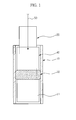
FIG. 1 is a sectional view showing a locking device for a pipe member according to an embodiment of the present inventive concept. -
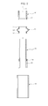
FIG. 2 is an exploded perspective view showing a locking device for a pipe member according to an embodiment of the present inventive concept. -
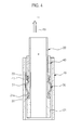
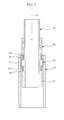
FIGS. 3 through 5 are sectional views showing operation of the locking device for a pipe member according to an embodiment of the present inventive concept. - Examples of the present inventive concept will be described below in more detail with reference to the accompanying drawings. The examples of the present inventive concept may, however, be embodied in different forms and should not be construed as limited to the examples set forth herein. Like reference numerals may refer to like elements throughout the specification.
- As shown in
FIGS. 1 and2 , a locking device for a pipe member according to an embodiment of the present inventive concept may include apipe member 10, a movingmember 20 slidably inserted into thepipe member 10, alocking member 30 mounted to an end portion of the movingmember 20 located inside thepipe member 10 in order to selectively allow the movingmember 20 to move in thepipe member 10, a transmittingmember 40 to dispersedly transmit external force to thelocking member 30, and acable 50 to connect the transmittingmember 40 to an external handle (not separately shown) or the like in order to transmit the force applied by a user to the transmittingmember 40. - The
pipe member 10 may be formed in a hollow cylindrical shape. Thelocking member 30 may be in close contact with or separated from an inner circumferential surface of thepipe member 10. - The
locking member 30 may be made of an elastically deformable material. Thelocking member 30 may include a first end connected to the movingmember 20 and a second end connected to the transmittingmember 40 in such a manner that thelocking member 30 is elastically deformed by external force transmitted to the transmittingmember 40 and is decreased in diameter. - The
locking member 30 may include alocking part 31 having an arc-shaped cross-section which protrudes outwardly so as to be easily elastically deformed and having a larger diameter than an inner diameter of thepipe member 10, a first insertingprotrusion 32 provided at the first end of thelocking member 30 so that the first end of thelocking member 30 is fixedly connected to the movingmember 20, and a second insertingprotrusion 33 provided at the second end of thelocking member 30 so that the second end of thelocking member 30 is fixedly connected to the transmittingmember 40. - As the
locking part 31 may have a larger diameter than the inner diameter of thepipe member 10, thelocking part 31 may be located inside thepipe member 10 in a partially elastically deformed state. Accordingly, frictional force may be applied between thelocking part 31 and the inner circumferential surface of thepipe member 10 by an elastic restoring force of thelocking member 30. - The moving
member 20 may include a supportingpart 21 provided at an end portion thereof to support the first end of thelocking member 30. The supportingpart 21 may be formed with afirst slot 21a such that the firstinserting protrusion 32 of thelocking member 30 may be inserted into and engaged with thefirst slot 21a. - The transmitting
member 40 may be formed in a ring shape, and may be slidably mounted around the movingmember 20. The transmittingmember 40 may be formed with asecond slot 41 at an inner surface of a first end portion thereof which may be in contact with the second end of thelocking member 30. The secondinserting protrusion 33 of thelocking member 30 may be inserted into and engaged with thesecond slot 41 of the transmittingmember 40. The external force supplied through thecable 50 may be transmitted to thelocking member 30 in a circumferentially dispersed manner by the transmittingmember 40. Accordingly, thelocking member 30 may be evenly deformed in a circumferential direction. - The
cable 50 may be connected to a second end portion of the transmittingmember 40 to apply force to the transmittingmember 40, such that the transmittingmember 40 moves along the movingmember 20. At this time, because the second end of thelocking member 30 may be connected to the transmittingmember 40, movement of the transmittingmember 40 may cause thelocking part 31 of thelocking member 30 to be elastically deformed and decreased in diameter. - Hereinafter, operation of the locking device for a pipe member according to an embodiment of the present inventive concept will be explained in detail with reference to the drawings.
- As shown in
FIG. 3 , when the movingmember 20 is located in a certain position, an outer circumferential surface of thelocking part 31 of thelocking member 30 may be kept in a close contact with the inner circumferential surface of thepipe member 10. Because thelocking part 31 may be disposed in a partially elastically deformed state inside thepipe member 10, frictional force may be applied between thelocking part 31 and the inner circumferential surface of thepipe member 10 by an elastic restoring force of thelocking part 31, thereby restricting movement of the movingmember 20. - If a user applies a force to a handle or the like in order to move the moving
member 20, the force may be transmitted to the transmittingmember 40 through thecable 50, and the transmittingmember 40 may move along an outer surface of the movingmember 20 as shown inFIG. 4 . Because the second end of thelocking member 30 may be connected to the transmittingmember 40, the second end of thelocking member 30 may also move with the transmittingmember 40. Accordingly, thelocking part 31 of thelocking member 30 may be elastically deformed and decreased in diameter. The decrease of the diameter of thelocking part 31 may cause the outer circumferential surface of thelocking part 31 to separate from the inner circumferential surface of thepipe member 10. Because movement of the movingmember 20 is not restricted by thelocking member 30, the movingmember 20 may move in thepipe member 10 by the force exerted on the movingmember 20 by a user. - After the moving
member 20 moves to a desired position, if a user releases the force applied to the handle, as shown inFIG. 5 , thelocking part 31 of thelocking member 30 may be elastically restored, and the diameter thereof may be increased to an original size. Accordingly, the outer circumferential surface of thelocking part 31 may come into close contact with the inner circumferential surface of thepipe member 10 again, thereby restricting movement of the movingmember 20. - Although a few embodiments of the present inventive concept have been shown and described, it would be appreciated by those skilled in the art that changes may be made in these embodiments without departing from the principles and spirit of the inventive concept, the scope of which is defined in the claims and their equivalents.
Claims (6)
- A locking device for a pipe member, comprising:a pipe member;a moving member, at least a portion of which is slidably disposed in the pipe member; anda locking member coupled to an end portion of the moving member, the locking member being made of an elastically deformable material and having an outer circumferential surface supported by an inner surface of the pipe member, whereinwhen an external force is transmitted to the locking member, the locking member is elastically deformed and is decreased in diameter.
- The locking device for a pipe member according to claim 1, further comprising:a transmitting member disposed in a ring shape, the transmitting member being slidably disposed around the moving member and connected to the locking member in order to transmit the external force to the locking member; anda cable connected to the transmitting member in order to transmit the external force to the transmitting member.
- The locking device for a pipe member according to claim 2, wherein the locking member includes a locking part configured to separate from the inner surface of the pipe member while being elastically deformed and decreased in diameter.
- The locking device for a pipe member according to claim 3, wherein the locking part has an arc-shaped cross-section which protrudes outwardly such that the locking part is elastically deformed.
- The locking device for a pipe member according to claim 3, wherein the locking part has a larger diameter than an inner diameter of the pipe member such that the locking part is supported by the inner surface of the pipe member in an elastically deformed state.
- The locking device for a pipe member according to claim 2, wherein:the locking member includes a first inserting protrusion disposed at a first end of the locking member to be connected to the moving member, and a second inserting protrusion disposed at a second end of the locking member to be connected to the transmitting member,the moving member includes a first slot such that the first inserting protrusion is inserted in and engaged with the first slot, andthe transmitting member includes a second slot such that the second inserting protrusion is inserted in and engaged with the second slot.
Applications Claiming Priority (1)
| Application Number | Priority Date | Filing Date | Title |
|---|---|---|---|
| KR1020120060649A KR101354602B1 (en) | 2012-06-05 | 2012-06-05 | Locking device for pipe member |
Publications (1)
| Publication Number | Publication Date |
|---|---|
| EP2672128A1 true EP2672128A1 (en) | 2013-12-11 |
Family
ID=48578832
Family Applications (1)
| Application Number | Title | Priority Date | Filing Date |
|---|---|---|---|
| EP13170582.4A Withdrawn EP2672128A1 (en) | 2012-06-05 | 2013-06-05 | Locking device for pipe member |
Country Status (3)
| Country | Link |
|---|---|
| US (1) | US20130320666A1 (en) |
| EP (1) | EP2672128A1 (en) |
| KR (1) | KR101354602B1 (en) |
Families Citing this family (4)
| Publication number | Priority date | Publication date | Assignee | Title |
|---|---|---|---|---|
| SE538241C2 (en) * | 2014-05-07 | 2016-04-12 | Xylem Ip Man Sarl | Guide tube assembly and guide tube holder therefore |
| CN106702704B (en) * | 2015-11-17 | 2020-10-02 | Seb公司 | Steam ironing apparatus comprising a hanger for placing garments to be ironed |
| US10844890B2 (en) * | 2017-11-16 | 2020-11-24 | Liberty Hardware Mfg. Corp. | Locking telescoping rod |
| US20260090530A1 (en) * | 2024-10-01 | 2026-04-02 | Jaime Buice | Systems, methods, and assemblies for providing a paddle with a stowed ready-to-use spear |
Citations (3)
| Publication number | Priority date | Publication date | Assignee | Title |
|---|---|---|---|---|
| DE876164C (en) * | 1951-07-24 | 1953-05-11 | Marno Soerensen | tripod |
| DE3202225A1 (en) * | 1982-01-25 | 1983-08-04 | Hannes 8100 Garmisch-Partenkirchen Marker | Device for clamping pipes which move telescopically in one another |
| GB2241995A (en) * | 1990-03-17 | 1991-09-18 | Colin Joseph Harwood | Round tube locking device under compression |
Family Cites Families (13)
| Publication number | Priority date | Publication date | Assignee | Title |
|---|---|---|---|---|
| US1034737A (en) * | 1911-11-20 | 1912-08-06 | Frank Green | Wall-packer for wells. |
| US2170574A (en) * | 1935-08-17 | 1939-08-22 | Detroit Hydrostatic Brake Corp | Hydraulic seal |
| US2243356A (en) * | 1939-08-14 | 1941-05-27 | Taylor Instrument Co | Sanitary fitting |
| US2691418A (en) * | 1951-06-23 | 1954-10-12 | John A Connolly | Combination packing cup and slips |
| US3048428A (en) * | 1960-01-29 | 1962-08-07 | Standard Oil Co | Hose nozzle end with radially expansible sleeves |
| JPS5250995U (en) * | 1975-10-09 | 1977-04-12 | ||
| GB8427046D0 (en) * | 1984-10-25 | 1984-11-28 | Raychem Sa Nv | Sealing device |
| JPH06265093A (en) * | 1993-03-10 | 1994-09-20 | Sony Corp | Tripod device |
| US5695222A (en) * | 1996-01-31 | 1997-12-09 | James Bruno | Ratchet type closet flange |
| KR200230022Y1 (en) * | 2001-01-15 | 2001-07-19 | 박우희 | Post Length Adjuster |
| US7441810B2 (en) * | 2005-09-07 | 2008-10-28 | Samuel Wayne Buff | Recreation vehicle waste pipe sealing unit |
| US7377556B2 (en) * | 2005-11-02 | 2008-05-27 | David Gian-Teh Ho | Self-centering adapter |
| DE102009037078A1 (en) * | 2009-08-13 | 2011-02-17 | Gl Gmbh Metall- Und Werkstatttechnik | Fluid communication means |
-
2012
- 2012-06-05 KR KR1020120060649A patent/KR101354602B1/en not_active Expired - Fee Related
-
2013
- 2013-06-05 US US13/910,762 patent/US20130320666A1/en not_active Abandoned
- 2013-06-05 EP EP13170582.4A patent/EP2672128A1/en not_active Withdrawn
Patent Citations (3)
| Publication number | Priority date | Publication date | Assignee | Title |
|---|---|---|---|---|
| DE876164C (en) * | 1951-07-24 | 1953-05-11 | Marno Soerensen | tripod |
| DE3202225A1 (en) * | 1982-01-25 | 1983-08-04 | Hannes 8100 Garmisch-Partenkirchen Marker | Device for clamping pipes which move telescopically in one another |
| GB2241995A (en) * | 1990-03-17 | 1991-09-18 | Colin Joseph Harwood | Round tube locking device under compression |
Also Published As
| Publication number | Publication date |
|---|---|
| US20130320666A1 (en) | 2013-12-05 |
| KR20130136889A (en) | 2013-12-13 |
| KR101354602B1 (en) | 2014-01-23 |
Similar Documents
| Publication | Publication Date | Title |
|---|---|---|
| CN101929516B (en) | Spring assembly and method of manufacturing the same | |
| JP5697277B2 (en) | Spring assembly | |
| US9150381B2 (en) | Expansion device for holding and securing rolled material | |
| US9234555B2 (en) | Spring seat member and spring assembly equipped with same | |
| US20130320666A1 (en) | Locking device for pipe member | |
| CN105799505B (en) | Spring device with hysteresis and pedal control characteristics | |
| JP5736480B2 (en) | Furniture leg cap | |
| JP2015133774A (en) | Clip for supporting wire group and wire harness | |
| JP2016020074A (en) | Writing instrument | |
| JP7009204B2 (en) | Spring assembly | |
| US9505320B2 (en) | Apparatus for adjusting seat height | |
| JP2014168828A (en) | Support device | |
| JP2013130240A (en) | Tension spring unit | |
| US9169919B2 (en) | Assembly of knob and lever | |
| KR102158063B1 (en) | Installation apparatus and method for installing a member to be installed on a fabric using an installation member | |
| KR102216944B1 (en) | Pumping device for vehicle seat | |
| JP6934389B2 (en) | Spring assembly | |
| JP5614862B1 (en) | Winding shaft | |
| KR101986138B1 (en) | Ball joint apparatus | |
| JP6796930B2 (en) | Shift stroke change adapter | |
| EP3669388B1 (en) | Assembly for mounting tiles made of a brittle material, such as ferrite | |
| JP6308432B2 (en) | Noise filter | |
| JP5838437B1 (en) | Camera support | |
| CN109562665A (en) | Upper suspension including the fixing piece relative to vehicle body, the component including this suspension and the method for this suspension to be bonded to vehicle body | |
| KR102229310B1 (en) | Rotating operation parts |
Legal Events
| Date | Code | Title | Description |
|---|---|---|---|
| PUAI | Public reference made under article 153(3) epc to a published international application that has entered the european phase |
Free format text: ORIGINAL CODE: 0009012 |
|
| AK | Designated contracting states |
Kind code of ref document: A1 Designated state(s): AL AT BE BG CH CY CZ DE DK EE ES FI FR GB GR HR HU IE IS IT LI LT LU LV MC MK MT NL NO PL PT RO RS SE SI SK SM TR |
|
| AX | Request for extension of the european patent |
Extension state: BA ME |
|
| 17P | Request for examination filed |
Effective date: 20140611 |
|
| RBV | Designated contracting states (corrected) |
Designated state(s): AL AT BE BG CH CY CZ DE DK EE ES FI FR GB GR HR HU IE IS IT LI LT LU LV MC MK MT NL NO PL PT RO RS SE SI SK SM TR |
|
| STAA | Information on the status of an ep patent application or granted ep patent |
Free format text: STATUS: THE APPLICATION HAS BEEN WITHDRAWN |
|
| 18W | Application withdrawn |
Effective date: 20151119 |