EP2671979A2 - Combing machine - Google Patents
Combing machine Download PDFInfo
- Publication number
- EP2671979A2 EP2671979A2 EP13169631.2A EP13169631A EP2671979A2 EP 2671979 A2 EP2671979 A2 EP 2671979A2 EP 13169631 A EP13169631 A EP 13169631A EP 2671979 A2 EP2671979 A2 EP 2671979A2
- Authority
- EP
- European Patent Office
- Prior art keywords
- sliver
- distance
- pair
- combing
- rollers
- Prior art date
- Legal status (The legal status is an assumption and is not a legal conclusion. Google has not performed a legal analysis and makes no representation as to the accuracy of the status listed.)
- Withdrawn
Links
- 238000006073 displacement reaction Methods 0.000 claims abstract description 34
- 238000001514 detection method Methods 0.000 claims description 32
- 230000002159 abnormal effect Effects 0.000 description 2
- 210000001520 comb Anatomy 0.000 description 2
- 230000005856 abnormality Effects 0.000 description 1
- 230000000694 effects Effects 0.000 description 1
- 230000001788 irregular Effects 0.000 description 1
- 238000005259 measurement Methods 0.000 description 1
- 239000002184 metal Substances 0.000 description 1
- 230000000737 periodic effect Effects 0.000 description 1
- 230000002093 peripheral effect Effects 0.000 description 1
- 230000004044 response Effects 0.000 description 1
- 238000000926 separation method Methods 0.000 description 1
Images

Classifications
-
- D—TEXTILES; PAPER
- D01—NATURAL OR MAN-MADE THREADS OR FIBRES; SPINNING
- D01G—PRELIMINARY TREATMENT OF FIBRES, e.g. FOR SPINNING
- D01G19/00—Combing machines
- D01G19/06—Details
- D01G19/26—Driving arrangements
Definitions
- the present invention relates to a combing machine.
- a combing machine which has a plurality of combing heads (e.g. eight combing heads) set parallel to each other.
- Each combing head has a pair of lap rollers, a nipper unit, a combing cylinder and a pair of detaching rollers.
- the nipper unit has a feed roller, a bottom nipper and a top nipper and holds the lap moved for a predetermined length by the pair of lap rollers and the feed roller.
- the combing cylinder combs the end of the lap and the combed fleece is moved toward the pair of detaching rollers by forward movement of the nipper unit.
- the paired detaching rollers are rotated in reverse direction to move back the previously drawn fleece (previous fleece).
- the rear end of the previous fleece and the front end of newly combed fleece (following fleece) are overlapped.
- fleece is drawn from the nipper unit and the rear end of the fleece is combed by the top comb pierced in the fleece.
- a pair of calender roller compresses the fleece made by the repetition of such operation and a sliver is formed. After the slivers fed by the respective combing heads are bundled into a single strand of sliver, the strand of sliver is drafted by a draft device and stored in a sliver can by a coiler.
- Japanese Patent Application Publication No. 8-260255 discloses a combing machine that maintains as even as possible the thickness of a combed sliver with lapse of the time.
- the combing machine includes a funnel-shaped sensor that transmits continuously electrical signals that are representative of the thickness of the sliver drafted by a draft device.
- the controller of the combing machine controls at least one of the aforementioned component parts of the combing head according to the output signal of the sensor.
- the causes of the variation of the thickness of the sliver include variation of the thickness of the lap fed to the nipper unit and poor separation of lap from the lap roll, i.e. part of the lap remaining on the inner lap in the roll without being unwound therefrom or part of the lap on the roll being attached to the lap being unwound from the roll.
- the signal-to-noise ratio of the sensor is relatively low. According to the combing machine wherein the sliver thickness variation is detected, the combing head that produces uneven sliver cannot be specified.
- the present invention is directed to a combing machine that detects thickness variation of a sliver delivered from each combing head of the combing machine with high accuracy.
- a combing machine includes a plurality of combing heads each having a pair of detaching rollers, a pair of calender rollers and a guide plate that is located between the pair of detaching rollers and the pair of calender rollers and guides motion of fleece.
- the combing machine is characterized in that the pair of calender rollers includes a drive roller and a driven roller. Distance between the drive roller and the driven roller is variable according to thickness of a sliver.
- Each combing head includes a displacement detector that detects displacement of the driven roller relative to the drive roller.
- the combing machine 10 includes a plurality of combing heads 11 (eight combing heads in the present embodiment) set parallel to each other.
- Each combing head 11 includes a pair of lap rollers 12 on which a lap L is placed.
- Each combing head 11 also includes a combing device (not shown) located downstream of the lap rollers 12, a guide plate 13 that guides and collects combed fleece F delivered from the combing device, and a roller unit 14 that draws and compresses the fleece F collected by the guide plate 13.
- a guide table 15 is located downstream of the roller units 14 and extends perpendicularly to the delivery direction of slivers S.
- the guide table 15 has thereon a plurality of guide rollers 16 for the respective combing heads 11 and a draft device 17 is located at a position adjacent to one end of the guide table 15.
- the slivers S delivered from the combing heads 11 are diverted around the respective guide rollers 16.
- the draft device 17 the slivers S are collected into a single sliver S and drafted.
- the drafted sliver S is put and stored in a sliver can by a coiler (not shown).
- the combing head 11 further includes a nipper unit 19, a combing cylinder 20 and two pairs of detaching rollers 21.
- the nipper unit 19 has a feed roller 18, and one pair of the detaching rollers 21 is located forward of the other pair of the detaching rollers 21 with respect to the moving direction of the fleece F.
- the nipper unit 19 further has a nipper frame 22 located above the combing cylinder 20 so as to be swingable back and forth.
- the nipper frame 22 has at the bottom thereof a bottom nipper 23.
- the nipper frame 22 further has a shaft 22A by which a nipper arm 24 is pivotally supported.
- a top nipper 24A is fixed to the distal end of the nipper arm 24.
- the top nipper 24A is movable in synchronization with the back-and-forth movement of the nipper frame 22 thereby to hold the lap L in conjunction with the bottom nipper 23.
- a top comb 25 is mounted through a mount (not shown) to the nipper frame 22 at a position that is forward of the bottom nipper 23 and operable to move in synchronization with the nipper frame 22.
- a reciprocally rotatable nipper shaft 26 is located behind the combing cylinder 20 and below the nipper frame 22.
- a nipper frame drive arm 27 is fixedly mounted at one end thereof on the nipper shaft 26 for rotation therewith.
- the nipper frame 22 is pivotally supported at the rear end thereof by a shaft 27A to which the nipper frame drive arm 27 is connected.
- the nipper frame 22 is swingable back and forth by the reciprocal rotation of the nipper shaft 26 so that the front end of the bottom nipper 23 is moved toward and away from the detaching rollers 21.
- the detaching rollers 21 are driven by a servomotor 28 that is provided independently of a main motor (not shown) of the combing machine.
- the roller unit 14 is located forward of the detaching rollers 21 (or leftward in Fig. 2 ) across the guide plate 13.
- the roller unit 14 has a pair of delivery rollers 29 and a pair of calender rollers 32.
- the pair of calender rollers 32 includes a drive roller 30 and a driven roller 31.
- the drive rollers 30 are mounted on a drive shaft 33 that is common to all the combing heads 11.
- the driven rollers 31 are urged against the respective drive rollers 30 and rotated by the rotation of the drive rollers 30.
- each drive roller 30 is fixed on the drive shaft 33 for rotation therewith.
- the drive shaft 33 extends through a support bracket 34 that supports the driven roller 31.
- a first shaft 35 is fixed at one end thereof to the support bracket 34 so as to extend parallel to the drive shaft 33.
- a first lever 36 is pivotally supported at one end thereof on the first shaft 35.
- a support shaft 37 is fixed at one end thereof to the other end of the first lever 36 and supports the driven roller 31 rotatably through a bearing (not shown).
- a cylindrical support 39 is formed at the other end of the first lever 36 so as to extend perpendicularly to and obliquely upward from the support shaft 37.
- the support 39 supports a coil spring 38 that urges the first lever 36 in the direction that moves the driven roller 31 toward the drive roller 30.
- the coil spring 38 is loosely wound around the support 39 and engaged at one end thereof with the first lever 36.
- the coil spring 38 serves as the urging member of the present invention.
- a second shaft 40 is fixed at one end thereof to the support bracket 34 on the side of the first shaft 35 that is opposite from the drive shaft 33 and extends parallel to the first shaft 35.
- a second lever 41 is pivotally supported on the second shaft 40.
- a support 43 is provided on the second lever 41 and supports a washer 42 that engages with the other end of the coil spring 38 and urges the coils spring 38 toward the first lever 36.
- the support 43 includes a shank 44 that pivotally extends through the second lever 41 and a bolt 45 that extends through and is fixed to the shank 44.
- the washer 42 is arranged so that one surface thereof is in contact with the coil spring 38 and the other surface is in contact with a flat portion formed on the shank 44.
- the coil spring 38 is held with one end thereof placed in contact with the first lever 36 and the other end thereof placed in contact with the washer 42 so as to urge the first lever 36 at a predetermined pressure in the direction that moves the driven roller 31 toward the drive roller 30.
- the urging force of the coil spring 38 is set so that the distance between the axes of the drive roller 30 and the axis of the driven roller 31 has a predetermined value when a sliver S having a predetermined thickness passes through the gap between the drive roller 30 and the driven roller 31.
- the support bracket 34 has a displacement detector 46 that detects any displacement of the driven roller 31 relative to the drive roller 30.
- the displacement detector 46 has a detection object 47 that is movable with the driven roller 31 and a distance sensor 48 that detects the distance thereof to the detection object 47.
- the distance sensor 48 serves as the distance detector of the present invention. That is, the displacement detector 46 detects the displacement of the driven roller 31 relative to the drive roller 30 by actually detecting the displacement of the detection object 47 movable with the driven roller 31.
- a sensor that measures the distance between the drive roller 30 and the driven roller 31 continuously is used as the distance sensor 48.
- the distance sensor 48 includes an eddy current displacement sensor and a laser displacement gauge.
- the detection object 47 is made of an L-shaped metal plate and fixed to the first lever 36.
- the detection object 47 has a flat portion 47A that is detected by the distance sensor 48.
- the detection object 47 is fixed to the first lever 36 so that the flat portion 47A is located at a reference position where the flat portion 47A is perpendicular to the plane including the axes of the drive roller 30 and the driven roller 31 and also parallel to the axis of the driven roller 31.
- the reference position means a position of the flat portion 47A at which a sliver S having a predetermined thickness is pressed against the drive roller 30 by the driven roller 31.
- the distance sensor 48 is fixed to a support plate 49 that is in turn fixed to the support bracket 34.
- the support plate 49 has a plate portion 49A to which the distance sensor 48 is fixed.
- the support plate 49 is fixed to the support bracket 34 so that the plate portion 49A is parallel to the flat portion 47A of the detection object 47 when the flat portion 47A is located at the reference position.
- Fig. 3 shows only a pair of calender rollers 32 for one of any two adjacent combing heads 11 and a pair of calender rollers 32, a displacement detector 46 and so forth of the other combing head 11 are provided on the other side of the support bracket 34 in a symmetrical manner.
- the servomotor 28, which drives the pairs of detaching rollers 21, is controlled by a controller 50 shown in Fig. 2 .
- the controller 50 controls the operation of the servomotor 28 in accordance with the detection signals of the distance sensors 48.
- the controller 50 serves as the piecing timing controller of the present invention that controls piecing timing by controlling the driving of the pairs of detaching rollers 21 so that the variation of the thickness of each sliver S falls within a preset range.
- the controller 50 controls not only the operation of the servomotor 28, but also the operation of other drive systems of the combing machine 10.
- the controller 50 converts the detection signal of each distance sensor 48 into a piecing peak for each fluctuation wavelength of the thickness of the sliver S and controls the piecing timing so that the piecing peak is kept at a preset value or less.
- the term "piecing peak” means a peak value of periodic fluctuation wavelength of the thickness of a sliver S that is caused by piecing fleece F. Data of allowable values of the piecing peak are stored in a memory (not shown) of the controller 50 for the respective operating conditions of the combing machine 10.
- the controller 50 controls the piecing timing by controlling the driving of the pairs of detaching rollers 21 in accordance with the detection signals of the distance sensors 48 so that the piecing peak is kept at the preset value or less.
- the bottom nipper 23 is moved back and forth and the top nipper 24A is moved up and down to hold and release the lap L between the top nipper 24A and the distal end of the bottom nipper 23.
- the detaching rollers 21 are driven by the servomotor 28 so as to make reciprocal pivoting motion in synchronization with the forward and backward movement of the bottom nipper 23.
- the detaching rollers 21 are reversed when the bottom nipper 23 is moved forward, and rotated in forward direction when the bottom nipper 23 is moved backward.
- the bottom nipper 23 is moved backward from the forward end position where the rotation of the detaching rollers 21 is stopped.
- the fleece F extending from the detaching rollers 21 to the nipping portion of the nipper unit 19 is cut off while the bottom nipper 23 is being moved backward.
- a train of cylinder needles (not shown) of the combing cylinder 20 combs the lap L hanging from the nipping portion.
- the train of cylinder needles is engaged with the lap L to keep the cylinder combing.
- the nipper frame 22 is moved forward from the backward end position of the bottom nipper 23 to disengage the train of cylinder needles from the lap L, combing operation of the combing cylinder 20 is finished.
- the detaching rollers 21 then start reverse rotation to move a previously drawn fleece (or preceding fleece) backward.
- the top nipper 24A is then opened with the bottom nipper 23 moved forward, and the feed roller 18 is rotated for a predetermined angle to feed a predetermined amount of lap L.
- the detaching rollers 21 then start forward rotation to pull out the preceding fleece, and a following fleece is pieced to the preceding fleece. At this time, needles of the top comb 25 are pierced into the fleece F.
- the nipper frame 22 reaches the forward end position by the continued forward movement of the bottom nipper 23, the forward rotation of the detaching rollers 21 is stopped.
- the piecing timing is controlled in such a way that the thickness of the piecing portion of the fleece F is adjusted. As a result, the thickness of the sliver S delivered from the calender rollers 32 is adjusted.
- the controller 50 controls the operation of the driving systems and the servomotor 28 according to the operating condition of the combing machine 10.
- a lap having a predetermined thickness and unwound from each lap L wound in the form of a roll is fed properly to the nipper unit 19 by the rotation of the lap rollers 12 and the feed roller 18, a sliver S having a predetermined thickness is delivered from the calender rollers 32.
- the lap L is separated from a lap roll in unwinding of the lap roll, there is a tendency that part of the lap remains on the inner lap in the roll without being unwound therefrom smoothly or part of the lap on the roll is attached to the lap being unwound from the roll and lap of such irregular thickness is supplied to the nipper unit 19.
- the thickness of the sliver S delivered from the calender rollers 32 is varied and deviates from the predetermined thickness.
- the distance sensor 48 detects the distance thereof to the flat portion 47A of the detection object 47 continuously.
- the driven roller 31 is held at the reference position. If the thickness of the sliver S is larger than the reference value, however, the driven roller 31 is moved in the direction away from the drive roller 30 by the sliver S.
- the first lever 36 is pivoted on the first shaft 35 in the direction that moves the flat portion 47A away from the distance sensor 48. If the thickness of the sliver S is smaller than the reference value, the driven roller 31 is moved toward the drive roller 30 by the urging force of the coil spring 38. Thus, the first lever 36 is pivoted on the first shaft 35 in the direction that moves the flat portion 47A toward the distance sensor 48.
- the distance sensor 48 detects the distance thereof to the flat portion 47A thereby to detect the variation of the thickness of the sliver S continuously.
- the controller 50 converts the detection signal of each distance sensor 48 into a piecing peak for each fluctuation wavelength of the thickness of the sliver S and controls the piecing timing so that the piecing peak is kept at a preset value or less.
- the variation of the thickness of the sliver S passing through the calender rollers 32 caused by the variation of the thickness of the supplied lap L is prevented from being continued until the quality of product sliver is affected.
- the distance sensor 48 which detects the variation of the thickness of the sliver delivered from the calender rollers 32 is operable to detect the fluctuation wavelength of the thickness of the sliver S with the signal-to-noise ratio kept in a good condition unlike in the case of the background-art sensor that detects the thickness of the doubled sliver S. Therefore, the variation of the thickness of the sliver S delivered from each combing head 11 is detectable with high accuracy.
- the combing machine of the present embodiment has the following advantageous effects.
- the controller 50 may determine whether or not the thickness of the sliver S falls within a preset range according to the detection signal of the distance sensor 48. If the thickness of the sliver S departs from the preset range, the controller 50 may control the piecing timing by controlling the driving of the pair of detaching rollers 21. In this case, the relational expression or map representing the relationship between the variation of the thickness of the sliver S from the reference thickness, which corresponds to the operating condition of the combing machine 10, and the detection signal of the distance sensor 48 corresponding to the variation is stored in a memory (not shown) of the controller 50.
- the driven roller 31 may slide along the drive roller 30.
- the coil spring 38 that urges the first lever 36 supporting the driven roller 31, in the direction that causes the driven roller 31 to move toward the drive roller 30 may be provided between the first lever 36 and a support that is fixed at a predetermined position. In this case, however, the force of the coil spring 38 that urges the sliver S through the driven roller 31 by the pivotal movement of the first lever 36 is varied, so that the variation of the detectable amount of the distance sensor 48 is not simply proportional to the variation of the thickness of the sliver S. Therefore, it is necessary to calculate the sliver thickness variation in view of the difference due to the variation of the urging force.
- the urging member that urges the driven roller 31 toward the drive roller 30 is not limited to the coil spring 38, but it may be a leaf spring.
- the displacement detector 46 detects the distance between the distance detector (or the distance sensor 48) and the driven roller 31 or the support shaft 37 of the driven roller 31 directly rather than detecting the distance between the drive roller 30 and the driven roller 31 indirectly.
- the use of the detection signal of the distance sensor 48 is not limited to controlling of the piecing timing.
- the detection signal of the distance sensor 48 may be used for controlling the driving of an adjustor that varies the piercing depth of the top comb 25 rather than controlling the piecing timing according to the detection signal of the distance sensor 48.
- the displacement detector 46 is not limited to the distance detector that measures the distance between the drive roller 30 and the driven roller 31 continuously and outputs the measurement results, but may have a detector that determines whether or not the thickness variation of the sliver S is a preset value or more. In this case, the detector is usable for detecting whether or not there is any peeling of the lap caused by licking.
- the controller 50 may be so configured as to output an abnormal signal when the variation of the thickness of the sliver S exceeds a preset range for a predetermined period of time and also to activate an alarm system in response to such abnormal signal. In this case, the operator notices the abnormality of the combing machine 10 at an early stage.
- a combing machine includes a plurality of combing heads each having a pair of detaching rollers, a pair of calender rollers and a guide plate that is located between the pair of detaching rollers and the pair of calender rollers and guides motion of fleece.
- the combing machine is characterized in that the pair of calender rollers includes a drive roller and a driven roller. Distance between the drive roller and the driven roller is variable according to thickness of a sliver.
- Each combing head includes a displacement detector that detects displacement of the driven roller relative to the drive roller.
Landscapes
- Engineering & Computer Science (AREA)
- Textile Engineering (AREA)
- Preliminary Treatment Of Fibers (AREA)
Abstract
A combing machine includes a plurality of combing heads each having a pair of detaching rollers, a pair of calender rollers and a guide plate that is located between the pair of detaching rollers and the pair of calender rollers and guides motion of fleece. The combing machine is characterized in that the pair of calender rollers includes a drive roller and a driven roller. Distance between the drive roller and the driven roller is variable according to thickness of a sliver. Each combing head includes a displacement detector that detects displacement of the driven roller relative to the drive roller.
Description
- The present invention relates to a combing machine.
- A combing machine is known which has a plurality of combing heads (e.g. eight combing heads) set parallel to each other. Each combing head has a pair of lap rollers, a nipper unit, a combing cylinder and a pair of detaching rollers. The nipper unit has a feed roller, a bottom nipper and a top nipper and holds the lap moved for a predetermined length by the pair of lap rollers and the feed roller. The combing cylinder combs the end of the lap and the combed fleece is moved toward the pair of detaching rollers by forward movement of the nipper unit. In accordance with the forward movement of the fleece, the paired detaching rollers are rotated in reverse direction to move back the previously drawn fleece (previous fleece). Thus, the rear end of the previous fleece and the front end of newly combed fleece (following fleece) are overlapped. When the paired detaching rollers are rotated in forward direction, fleece is drawn from the nipper unit and the rear end of the fleece is combed by the top comb pierced in the fleece. A pair of calender roller compresses the fleece made by the repetition of such operation and a sliver is formed. After the slivers fed by the respective combing heads are bundled into a single strand of sliver, the strand of sliver is drafted by a draft device and stored in a sliver can by a coiler.
- Japanese Patent Application Publication No.
8-260255 - The causes of the variation of the thickness of the sliver include variation of the thickness of the lap fed to the nipper unit and poor separation of lap from the lap roll, i.e. part of the lap remaining on the inner lap in the roll without being unwound therefrom or part of the lap on the roll being attached to the lap being unwound from the roll. In the above-described combing machine wherein the thickness of the sliver drafted by the draft device or the thickness of the sliver made by doubling a plurality of sliver is detected, the signal-to-noise ratio of the sensor is relatively low. According to the combing machine wherein the sliver thickness variation is detected, the combing head that produces uneven sliver cannot be specified.
- The present invention is directed to a combing machine that detects thickness variation of a sliver delivered from each combing head of the combing machine with high accuracy.
- In accordance with an aspect of the present invention, a combing machine includes a plurality of combing heads each having a pair of detaching rollers, a pair of calender rollers and a guide plate that is located between the pair of detaching rollers and the pair of calender rollers and guides motion of fleece. The combing machine is characterized in that the pair of calender rollers includes a drive roller and a driven roller. Distance between the drive roller and the driven roller is variable according to thickness of a sliver. Each combing head includes a displacement detector that detects displacement of the driven roller relative to the drive roller.
- Other aspects and advantages of the invention will become apparent from the following description, taken in conjunction with the accompanying drawings, illustrating by way of example the principles of the invention.
- The invention together with objects and advantages thereof, may best be understood by reference to the following description of the presently preferred embodiments together with the accompanying drawings in which:
-
Fig. 1 is a plan view showing a combing machine according to an embodiment of the present invention; -
Fig. 2 is a side view showing a combing head of the combing machine ofFig 1 ; and -
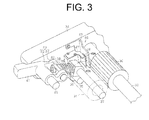
Fig. 3 is a perspective view showing a support bracket that supports a driven roller and a displacement detector of the combing machine ofFig 1 . - The following will describe the combing machine according to the embodiment of the present invention with reference to
Figs. 1 through 3 . Referring toFig. 1 , thecombing machine 10 includes a plurality of combing heads 11 (eight combing heads in the present embodiment) set parallel to each other. Each combinghead 11 includes a pair oflap rollers 12 on which a lap L is placed. Each combinghead 11 also includes a combing device (not shown) located downstream of thelap rollers 12, aguide plate 13 that guides and collects combed fleece F delivered from the combing device, and aroller unit 14 that draws and compresses the fleece F collected by theguide plate 13. A guide table 15 is located downstream of theroller units 14 and extends perpendicularly to the delivery direction of slivers S. The guide table 15 has thereon a plurality ofguide rollers 16 for therespective combing heads 11 and a draft device 17 is located at a position adjacent to one end of the guide table 15. The slivers S delivered from thecombing heads 11 are diverted around therespective guide rollers 16. In the draft device 17, the slivers S are collected into a single sliver S and drafted. The drafted sliver S is put and stored in a sliver can by a coiler (not shown). - Referring to
Fig. 2 , the combinghead 11 further includes anipper unit 19, a combingcylinder 20 and two pairs of detachingrollers 21. Thenipper unit 19 has afeed roller 18, and one pair of the detachingrollers 21 is located forward of the other pair of the detachingrollers 21 with respect to the moving direction of the fleece F. Thenipper unit 19 further has anipper frame 22 located above the combingcylinder 20 so as to be swingable back and forth. Thenipper frame 22 has at the bottom thereof abottom nipper 23. Thenipper frame 22 further has ashaft 22A by which anipper arm 24 is pivotally supported. Atop nipper 24A is fixed to the distal end of thenipper arm 24. Thetop nipper 24A is movable in synchronization with the back-and-forth movement of thenipper frame 22 thereby to hold the lap L in conjunction with thebottom nipper 23. Atop comb 25 is mounted through a mount (not shown) to thenipper frame 22 at a position that is forward of thebottom nipper 23 and operable to move in synchronization with thenipper frame 22. - A reciprocally
rotatable nipper shaft 26 is located behind the combingcylinder 20 and below thenipper frame 22. A nipperframe drive arm 27 is fixedly mounted at one end thereof on thenipper shaft 26 for rotation therewith. Thenipper frame 22 is pivotally supported at the rear end thereof by ashaft 27A to which the nipperframe drive arm 27 is connected. Thenipper frame 22 is swingable back and forth by the reciprocal rotation of thenipper shaft 26 so that the front end of thebottom nipper 23 is moved toward and away from the detachingrollers 21. In the present embodiment, the detachingrollers 21 are driven by aservomotor 28 that is provided independently of a main motor (not shown) of the combing machine. - The
roller unit 14 is located forward of the detaching rollers 21 (or leftward inFig. 2 ) across theguide plate 13. Theroller unit 14 has a pair ofdelivery rollers 29 and a pair ofcalender rollers 32. The pair ofcalender rollers 32 includes adrive roller 30 and a drivenroller 31. Thedrive rollers 30 are mounted on a drive shaft 33 that is common to all thecombing heads 11. The drivenrollers 31 are urged against therespective drive rollers 30 and rotated by the rotation of thedrive rollers 30. - The following will describe each pair of the
calender rollers 32. Referring toFig. 3 , eachdrive roller 30 is fixed on the drive shaft 33 for rotation therewith. The drive shaft 33 extends through asupport bracket 34 that supports the drivenroller 31. A first shaft 35 is fixed at one end thereof to thesupport bracket 34 so as to extend parallel to the drive shaft 33. Afirst lever 36 is pivotally supported at one end thereof on the first shaft 35. Asupport shaft 37 is fixed at one end thereof to the other end of thefirst lever 36 and supports the drivenroller 31 rotatably through a bearing (not shown). A cylindrical support 39 is formed at the other end of thefirst lever 36 so as to extend perpendicularly to and obliquely upward from thesupport shaft 37. The support 39 supports a coil spring 38 that urges thefirst lever 36 in the direction that moves the drivenroller 31 toward thedrive roller 30. The coil spring 38 is loosely wound around the support 39 and engaged at one end thereof with thefirst lever 36. The coil spring 38 serves as the urging member of the present invention. - A
second shaft 40 is fixed at one end thereof to thesupport bracket 34 on the side of the first shaft 35 that is opposite from the drive shaft 33 and extends parallel to the first shaft 35. Asecond lever 41 is pivotally supported on thesecond shaft 40. Asupport 43 is provided on thesecond lever 41 and supports awasher 42 that engages with the other end of the coil spring 38 and urges the coils spring 38 toward thefirst lever 36. Thesupport 43 includes ashank 44 that pivotally extends through thesecond lever 41 and abolt 45 that extends through and is fixed to theshank 44. Thewasher 42 is arranged so that one surface thereof is in contact with the coil spring 38 and the other surface is in contact with a flat portion formed on theshank 44. The coil spring 38 is held with one end thereof placed in contact with thefirst lever 36 and the other end thereof placed in contact with thewasher 42 so as to urge thefirst lever 36 at a predetermined pressure in the direction that moves the drivenroller 31 toward thedrive roller 30. The urging force of the coil spring 38 is set so that the distance between the axes of thedrive roller 30 and the axis of the drivenroller 31 has a predetermined value when a sliver S having a predetermined thickness passes through the gap between thedrive roller 30 and the drivenroller 31. - The
support bracket 34 has adisplacement detector 46 that detects any displacement of the drivenroller 31 relative to thedrive roller 30. Thedisplacement detector 46 has a detection object 47 that is movable with the drivenroller 31 and adistance sensor 48 that detects the distance thereof to the detection object 47. Thedistance sensor 48 serves as the distance detector of the present invention. That is, thedisplacement detector 46 detects the displacement of the drivenroller 31 relative to thedrive roller 30 by actually detecting the displacement of the detection object 47 movable with the drivenroller 31. A sensor that measures the distance between thedrive roller 30 and the drivenroller 31 continuously is used as thedistance sensor 48. Thedistance sensor 48 includes an eddy current displacement sensor and a laser displacement gauge. - The detection object 47 is made of an L-shaped metal plate and fixed to the
first lever 36. The detection object 47 has aflat portion 47A that is detected by thedistance sensor 48. The detection object 47 is fixed to thefirst lever 36 so that theflat portion 47A is located at a reference position where theflat portion 47A is perpendicular to the plane including the axes of thedrive roller 30 and the drivenroller 31 and also parallel to the axis of the drivenroller 31. The reference position means a position of theflat portion 47A at which a sliver S having a predetermined thickness is pressed against thedrive roller 30 by the drivenroller 31. Thedistance sensor 48 is fixed to asupport plate 49 that is in turn fixed to thesupport bracket 34. Thesupport plate 49 has aplate portion 49A to which thedistance sensor 48 is fixed. Thesupport plate 49 is fixed to thesupport bracket 34 so that theplate portion 49A is parallel to theflat portion 47A of the detection object 47 when theflat portion 47A is located at the reference position. - It is noted that
Fig. 3 shows only a pair ofcalender rollers 32 for one of any two adjacent combingheads 11 and a pair ofcalender rollers 32, adisplacement detector 46 and so forth of the other combinghead 11 are provided on the other side of thesupport bracket 34 in a symmetrical manner. - The
servomotor 28, which drives the pairs of detachingrollers 21, is controlled by a controller 50 shown inFig. 2 . The controller 50 controls the operation of theservomotor 28 in accordance with the detection signals of thedistance sensors 48. The controller 50 serves as the piecing timing controller of the present invention that controls piecing timing by controlling the driving of the pairs of detachingrollers 21 so that the variation of the thickness of each sliver S falls within a preset range. The controller 50 controls not only the operation of theservomotor 28, but also the operation of other drive systems of the combingmachine 10. - The controller 50 converts the detection signal of each
distance sensor 48 into a piecing peak for each fluctuation wavelength of the thickness of the sliver S and controls the piecing timing so that the piecing peak is kept at a preset value or less. The term "piecing peak" means a peak value of periodic fluctuation wavelength of the thickness of a sliver S that is caused by piecing fleece F. Data of allowable values of the piecing peak are stored in a memory (not shown) of the controller 50 for the respective operating conditions of the combingmachine 10. The controller 50 controls the piecing timing by controlling the driving of the pairs of detachingrollers 21 in accordance with the detection signals of thedistance sensors 48 so that the piecing peak is kept at the preset value or less. - The following will describe the operation of the combing
machine 10. In accordance with the reciprocal rotation of thenipper shaft 26 driven by a main motor (not shown), thebottom nipper 23 is moved back and forth and thetop nipper 24A is moved up and down to hold and release the lap L between thetop nipper 24A and the distal end of thebottom nipper 23. The detachingrollers 21 are driven by theservomotor 28 so as to make reciprocal pivoting motion in synchronization with the forward and backward movement of thebottom nipper 23. The detachingrollers 21 are reversed when thebottom nipper 23 is moved forward, and rotated in forward direction when thebottom nipper 23 is moved backward. - The
bottom nipper 23 is moved backward from the forward end position where the rotation of the detachingrollers 21 is stopped. The fleece F extending from the detachingrollers 21 to the nipping portion of thenipper unit 19 is cut off while thebottom nipper 23 is being moved backward. A train of cylinder needles (not shown) of the combingcylinder 20 combs the lap L hanging from the nipping portion. When thebottom nipper 23 is located at the backward end position, the train of cylinder needles is engaged with the lap L to keep the cylinder combing. When thenipper frame 22 is moved forward from the backward end position of thebottom nipper 23 to disengage the train of cylinder needles from the lap L, combing operation of the combingcylinder 20 is finished. - The detaching
rollers 21 then start reverse rotation to move a previously drawn fleece (or preceding fleece) backward. Thetop nipper 24A is then opened with thebottom nipper 23 moved forward, and thefeed roller 18 is rotated for a predetermined angle to feed a predetermined amount of lap L. The detachingrollers 21 then start forward rotation to pull out the preceding fleece, and a following fleece is pieced to the preceding fleece. At this time, needles of thetop comb 25 are pierced into the fleece F. When thenipper frame 22 reaches the forward end position by the continued forward movement of thebottom nipper 23, the forward rotation of the detachingrollers 21 is stopped. By controlling the operation of the detachingrollers 21, that is, by controlling the timing of the forward rotation, the reverse rotation and stopping of the detachingrollers 21, the piecing timing is controlled in such a way that the thickness of the piecing portion of the fleece F is adjusted. As a result, the thickness of the sliver S delivered from thecalender rollers 32 is adjusted. - The controller 50 controls the operation of the driving systems and the
servomotor 28 according to the operating condition of the combingmachine 10. When a lap having a predetermined thickness and unwound from each lap L wound in the form of a roll is fed properly to thenipper unit 19 by the rotation of thelap rollers 12 and thefeed roller 18, a sliver S having a predetermined thickness is delivered from thecalender rollers 32. When the lap L is separated from a lap roll in unwinding of the lap roll, there is a tendency that part of the lap remains on the inner lap in the roll without being unwound therefrom smoothly or part of the lap on the roll is attached to the lap being unwound from the roll and lap of such irregular thickness is supplied to thenipper unit 19. In such a case, the thickness of the sliver S delivered from thecalender rollers 32 is varied and deviates from the predetermined thickness. - The
distance sensor 48 detects the distance thereof to theflat portion 47A of the detection object 47 continuously. When the thickness of the sliver S is at a reference value corresponding to the preset operating condition of the combingmachine 10, the drivenroller 31 is held at the reference position. If the thickness of the sliver S is larger than the reference value, however, the drivenroller 31 is moved in the direction away from thedrive roller 30 by the sliver S. Thus, thefirst lever 36 is pivoted on the first shaft 35 in the direction that moves theflat portion 47A away from thedistance sensor 48. If the thickness of the sliver S is smaller than the reference value, the drivenroller 31 is moved toward thedrive roller 30 by the urging force of the coil spring 38. Thus, thefirst lever 36 is pivoted on the first shaft 35 in the direction that moves theflat portion 47A toward thedistance sensor 48. Thedistance sensor 48 detects the distance thereof to theflat portion 47A thereby to detect the variation of the thickness of the sliver S continuously. - The controller 50 converts the detection signal of each
distance sensor 48 into a piecing peak for each fluctuation wavelength of the thickness of the sliver S and controls the piecing timing so that the piecing peak is kept at a preset value or less. The variation of the thickness of the sliver S passing through thecalender rollers 32 caused by the variation of the thickness of the supplied lap L is prevented from being continued until the quality of product sliver is affected. Thedistance sensor 48 which detects the variation of the thickness of the sliver delivered from thecalender rollers 32 is operable to detect the fluctuation wavelength of the thickness of the sliver S with the signal-to-noise ratio kept in a good condition unlike in the case of the background-art sensor that detects the thickness of the doubled sliver S. Therefore, the variation of the thickness of the sliver S delivered from each combinghead 11 is detectable with high accuracy. - The combing machine of the present embodiment has the following advantageous effects.
- (1) The combing
machine 10 includes a plurality of combingheads 11 each having pairs of detachingrollers 21, a pair ofcalender rollers 32 and aguide plate 13 that is located between the pairs of detachingrollers 21 and the pair ofcalender rollers 32 and guides motion of fleece F. The pair ofcalender rollers 32 is configured so that the distance between thedrive roller 30 and the drivenroller 31 is variable according to the thickness of the sliver S. Each combinghead 11 has adisplacement detector 46 that detects the displacement of the drivenroller 31 relative to thedrive roller 30. Therefore, the variation of the thickness of the sliver S delivered from each combinghead 11 is detectable with high accuracy. - (2) Unlike in the case of the background art wherein the sensor detects the thickness of the doubled sliver S, the use of the
distance sensors 48 in the present embodiment that detect the variation of the thickness of the slivers S delivered from the respective pairs ofcalender rollers 32 makes it possible to identify with ease the combinghead 11 where the variation of the thickness of the sliver S occurs. Compared to the background art wherein the sensor detects the variation of the doubled and drafted sliver S, in the present embodiment, the distance between the sliver S whose piecing timing has been controlled and thedisplacement detector 46 is reduced, so that it is confirmed at an early stage whether or not controlling of the piecing timing is performed appropriately. - (3) The
displacement detector 46 has a distance detector (or distance sensor 48) that measures the distance between thedrive roller 30 and the drivenroller 31 continuously. The detection results of thedisplacement detector 46 are usable for various purposes. For example, when the detection results of thedisplacement detector 46 are used for automatically controlling the piecing timing, the displacement detector that detects the distance between thedrive roller 30 and the drivenroller 31 continuously allows the control of the piecing timing to be performed more appropriately than a displacement detector that detects the distance intermittently. - (4) The combing
machine 10 includes a piecing timing controller (or the controller 50) that controls piecing timing by controlling the driving of the pairs of detachingrollers 21 according to the detection signal of thedistance sensor 48 so that the variation of the thickness of the sliver S falls within a preset range. In the present embodiment wherein the variation of the thickness of the sliver S delivered from thecalender roller 32 of each combinghead 11 falls within a preset range, a doubled and drafted sliver of an intended quality is obtained. - (5) The piecing timing controller converts the detection signal of each distance detector into a piecing peak for each fluctuation wavelength of the thickness of the sliver S and controls the piecing timing so that the piecing peak is kept at a preset value or less. Therefore, the piecing timing controller controls the piecing timing more easily than a piecing timing controller that controls piecing timing so as to correspond to all the variation of the thickness of the sliver detected continuously.
- (6) The
displacement detector 46 has the detection object 47 and the distance detector (or the distance sensor 48). The detection object 47 is movable with the drivenroller 31 and, therefore, the distance of the detection object 47 from thedrive roller 30 is variable. The distance detector detects the distance thereof to the detection object 47. Therefore, thedisplacement detector 46 of the present embodiment helps to increase the degree of freedom of arrangement of the distance detector thereby to easily ensure the space for placing thedisplacement detector 46 as compared to the case where a distance detector detects the drivenroller 31 directly. - (7) The driven
roller 31 is rotatably provided at one end of thefirst lever 36 that is pivotally provided to the first shaft 35 provided parallel to the drive shaft 33. The coil spring 38 that urges thefirst lever 36 in the direction in which the drivenroller 31 is moved toward thedrive roller 30 is provided between thefirst lever 36 and thesecond lever 41 that is pivoted in conjunction with the pivotal movement of thefirst lever 36. Therefore, unlike in the case where the coil spring 38 is provided between thesecond lever 41 and a fixed support, according to the present embodiment, when the thickness of the sliver S is made larger than the reference thickness, thefirst lever 36 is pivoted without increasing the urging force of the coil spring 38. Thus, thefirst lever 36 makes pivotal movement according to the variation of the thickness of the sliver S, with the result that the accuracy of the detection results of thedistance sensor 48 is enhanced. - (8) Although the thickness of the sliver S is directly detected by the peripheral surface of the driven
roller 31, the distance of the drivenroller 31 from thedrive roller 30 is varied by the pivotal movement of thefirst lever 36 because the drivenroller 31 is supported by thefirst lever 36. Therefore, unlike in the background art funnel-shaped sensor, thedisplacement detector 46 of the present embodiment allows a sliver to be passed easily through a detected area. - The present invention has been described in the context of the above embodiment, but it is not limited to the embodiment. It is obvious to those skilled in the art that the invention may be practiced in various manners as exemplified below.
- The controller 50 may determine whether or not the thickness of the sliver S falls within a preset range according to the detection signal of the
distance sensor 48. If the thickness of the sliver S departs from the preset range, the controller 50 may control the piecing timing by controlling the driving of the pair of detachingrollers 21. In this case, the relational expression or map representing the relationship between the variation of the thickness of the sliver S from the reference thickness, which corresponds to the operating condition of the combingmachine 10, and the detection signal of thedistance sensor 48 corresponding to the variation is stored in a memory (not shown) of the controller 50. - As a structure wherein the distance of the driven
roller 31 from thedrive roller 30 is varied according to the thickness of the sliver S, the drivenroller 31 may slide along thedrive roller 30. - The coil spring 38 that urges the
first lever 36 supporting the drivenroller 31, in the direction that causes the drivenroller 31 to move toward thedrive roller 30 may be provided between thefirst lever 36 and a support that is fixed at a predetermined position. In this case, however, the force of the coil spring 38 that urges the sliver S through the drivenroller 31 by the pivotal movement of thefirst lever 36 is varied, so that the variation of the detectable amount of thedistance sensor 48 is not simply proportional to the variation of the thickness of the sliver S. Therefore, it is necessary to calculate the sliver thickness variation in view of the difference due to the variation of the urging force. - The urging member that urges the driven
roller 31 toward thedrive roller 30 is not limited to the coil spring 38, but it may be a leaf spring. - It may be so arranged that the
displacement detector 46 detects the distance between the distance detector (or the distance sensor 48) and the drivenroller 31 or thesupport shaft 37 of the drivenroller 31 directly rather than detecting the distance between thedrive roller 30 and the drivenroller 31 indirectly. - The use of the detection signal of the
distance sensor 48 is not limited to controlling of the piecing timing. The detection signal of thedistance sensor 48 may be used for controlling the driving of an adjustor that varies the piercing depth of thetop comb 25 rather than controlling the piecing timing according to the detection signal of thedistance sensor 48. - The
displacement detector 46 is not limited to the distance detector that measures the distance between thedrive roller 30 and the drivenroller 31 continuously and outputs the measurement results, but may have a detector that determines whether or not the thickness variation of the sliver S is a preset value or more. In this case, the detector is usable for detecting whether or not there is any peeling of the lap caused by licking. - The controller 50 may be so configured as to output an abnormal signal when the variation of the thickness of the sliver S exceeds a preset range for a predetermined period of time and also to activate an alarm system in response to such abnormal signal. In this case, the operator notices the abnormality of the combing
machine 10 at an early stage. - A combing machine includes a plurality of combing heads each having a pair of detaching rollers, a pair of calender rollers and a guide plate that is located between the pair of detaching rollers and the pair of calender rollers and guides motion of fleece. The combing machine is characterized in that the pair of calender rollers includes a drive roller and a driven roller. Distance between the drive roller and the driven roller is variable according to thickness of a sliver. Each combing head includes a displacement detector that detects displacement of the driven roller relative to the drive roller.
Claims (5)
- A combing machine (10) including a plurality of combing heads (11) each having a pair of detaching rollers (21), a pair of calender rollers (32) and a guide plate (13) that is located between the pair of detaching rollers (21) and the pair of calender rollers (32) and guides motion of fleece (F), characterized in that
the pair of calender rollers (32) includes a drive roller (30) and a driven roller (31), wherein distance between the drive roller (30) and the driven roller (31) is variable according to thickness of a sliver (S), wherein each combing head (11) includes a displacement detector (46) that detects displacement of the driven roller (31) relative to the drive roller (30). - The combing machine (10) according to claim 1, characterized in that the displacement detector (46) includes a distance detector (48) that measures the distance between the drive roller (30) and the driven roller (31) continuously.
- The combing machine (10) according to claim 2, characterized in that the combing machine (10) includes a piecing timing controller (50) that controls piecing timing by controlling driving of the pairs of detaching rollers (21) according to detection signals of the distance detectors (48) so that variation of the thickness of the sliver (S) for each pair of calender rollers (32) falls within a preset range.
- The combing machine (10) according to claim 3, characterized in that the piecing timing controller (50) converts the detection signal of each distance detector (48) into a piecing peak for each fluctuation wavelength of the thickness of the sliver (S) and controls the piecing timing so that the piecing peak is kept at a preset value or less.
- The combing machine (10) according to any one of claims 1 through 4, characterized in that the displacement detector (46) has a detection object (47) and a distance detector (48), wherein the detection object (47) is movable with the driven roller (31) and distance of the detection object (47) from the drive roller (30) is variable, wherein the distance detector (48) detects distance thereof to the detection object (47).
Applications Claiming Priority (1)
| Application Number | Priority Date | Filing Date | Title |
|---|---|---|---|
| JP2012130030A JP2013253345A (en) | 2012-06-07 | 2012-06-07 | Comber |
Publications (1)
| Publication Number | Publication Date |
|---|---|
| EP2671979A2 true EP2671979A2 (en) | 2013-12-11 |
Family
ID=48537820
Family Applications (1)
| Application Number | Title | Priority Date | Filing Date |
|---|---|---|---|
| EP13169631.2A Withdrawn EP2671979A2 (en) | 2012-06-07 | 2013-05-29 | Combing machine |
Country Status (3)
| Country | Link |
|---|---|
| EP (1) | EP2671979A2 (en) |
| JP (1) | JP2013253345A (en) |
| CN (1) | CN103484979A (en) |
Cited By (5)
| Publication number | Priority date | Publication date | Assignee | Title |
|---|---|---|---|---|
| EP2918711A3 (en) * | 2014-03-11 | 2016-03-09 | Kabushiki Kaisha Toyota Jidoshokki | Automatic lap splicing apparatus |
| EP3031962A1 (en) * | 2014-12-10 | 2016-06-15 | Kabushiki Kaisha Toyota Jidoshokki | Detaching top roller supporting portion for comber |
| CN107326481A (en) * | 2017-07-16 | 2017-11-07 | 经纬纺织机械股份有限公司 | A kind of device of simple eye Photoelectric Detection sliver broken strip and its combing machine of application |
| CN110172757A (en) * | 2019-06-25 | 2019-08-27 | 中原工学院 | A kind of device and method improving combing sliver quality |
| WO2023061689A1 (en) * | 2021-10-14 | 2023-04-20 | Trützschler Group SE | Combing machine and method for operating a combing machine |
Families Citing this family (2)
| Publication number | Priority date | Publication date | Assignee | Title |
|---|---|---|---|---|
| CH709899A2 (en) * | 2014-07-21 | 2016-01-29 | Rieter Ag Maschf | Frame for a combing machine. |
| CN104532414B (en) * | 2014-11-27 | 2017-09-15 | 中原工学院 | A kind of conveying device for being used to eliminate combing machine table top broken strip |
Citations (1)
| Publication number | Priority date | Publication date | Assignee | Title |
|---|---|---|---|---|
| JPH08260255A (en) | 1995-03-28 | 1996-10-08 | Mas Fab Rieter Ag | Combing machine |
Family Cites Families (5)
| Publication number | Priority date | Publication date | Assignee | Title |
|---|---|---|---|---|
| CH675885A5 (en) * | 1988-09-21 | 1990-11-15 | Rieter Ag Maschf | |
| DE102007039067A1 (en) * | 2007-08-17 | 2009-02-19 | TRüTZSCHLER GMBH & CO. KG | Device on a comber for monitoring Kämmlingsanteils |
| DE102008049363B4 (en) * | 2008-08-19 | 2022-10-13 | Trützschler Group SE | Device for or on a spinning preparation machine, which has a drafting system for drafting strand-like fiber material |
| DE102008047156B4 (en) * | 2008-09-12 | 2025-04-30 | Trützschler Group SE | Device for or on a spinning preparation machine, in particular a card, draw frame, comber or flyer, for correcting a measuring signal |
| JP5924855B2 (en) * | 2010-06-16 | 2016-05-25 | 株式会社豊田自動織機 | Comb |
-
2012
- 2012-06-07 JP JP2012130030A patent/JP2013253345A/en active Pending
-
2013
- 2013-05-29 EP EP13169631.2A patent/EP2671979A2/en not_active Withdrawn
- 2013-06-06 CN CN201310222867.7A patent/CN103484979A/en active Pending
Patent Citations (1)
| Publication number | Priority date | Publication date | Assignee | Title |
|---|---|---|---|---|
| JPH08260255A (en) | 1995-03-28 | 1996-10-08 | Mas Fab Rieter Ag | Combing machine |
Cited By (7)
| Publication number | Priority date | Publication date | Assignee | Title |
|---|---|---|---|---|
| EP2918711A3 (en) * | 2014-03-11 | 2016-03-09 | Kabushiki Kaisha Toyota Jidoshokki | Automatic lap splicing apparatus |
| EP3031962A1 (en) * | 2014-12-10 | 2016-06-15 | Kabushiki Kaisha Toyota Jidoshokki | Detaching top roller supporting portion for comber |
| CN107326481A (en) * | 2017-07-16 | 2017-11-07 | 经纬纺织机械股份有限公司 | A kind of device of simple eye Photoelectric Detection sliver broken strip and its combing machine of application |
| CN107326481B (en) * | 2017-07-16 | 2023-08-08 | 经纬智能纺织机械有限公司 | A single-eye photoelectric detection device for cotton sliver breakage and its applied combing machine |
| CN110172757A (en) * | 2019-06-25 | 2019-08-27 | 中原工学院 | A kind of device and method improving combing sliver quality |
| CN110172757B (en) * | 2019-06-25 | 2020-07-03 | 中原工学院 | A device and method for improving the quality of combed sliver |
| WO2023061689A1 (en) * | 2021-10-14 | 2023-04-20 | Trützschler Group SE | Combing machine and method for operating a combing machine |
Also Published As
| Publication number | Publication date |
|---|---|
| CN103484979A (en) | 2014-01-01 |
| JP2013253345A (en) | 2013-12-19 |
Similar Documents
| Publication | Publication Date | Title |
|---|---|---|
| US11597546B2 (en) | Method for actuating the band driving device of a strapping machine and corresponding strapping machine | |
| US7926147B2 (en) | Apparatus for the fibre-sorting or fibre-selection of a fibre bundle comprising textile fibres, especially for combing | |
| JP2013253345A (en) | Comber | |
| US7765648B2 (en) | Apparatus for detecting a parameter at a plurality of slivers fed to a drafting system of a spinning machine | |
| US8863785B2 (en) | Mounting device for all-steel card clothings | |
| JP5543145B2 (en) | Apparatus for or in a spinning pretreatment machine having a drilling mechanism for drawing fiber material in the form of stranded wire | |
| EP2759623A1 (en) | Spinning machine, take-up device, and textile machine | |
| CN115676513A (en) | Device for drawing and winding a thread | |
| JP2015172256A (en) | Device for automatically splicing wraps | |
| CN1077156C (en) | Combining machine | |
| US5621948A (en) | Method and apparatus for severing a sliver during coiler can replacement in a drawing frame | |
| CN108792808A (en) | A kind of automatic precision receives strand winding apparatus and method | |
| US6543093B2 (en) | Apparatus for detecting displacements and/or presence of sliver in a fiber processing machine | |
| CN106435853B (en) | Combing machine | |
| EP2186932A1 (en) | Yarn-feeding apparatus for textile machines, with control of the feeding parameters | |
| JP5612285B2 (en) | Apparatus for or in a spinning pretreatment machine having a drilling mechanism for drawing fiber material in the form of stranded wire | |
| CN113454275A (en) | Method and textile machine for automatically adjusting and stabilizing the distance defined between a rotatably mounted cylinder and another component | |
| US7650672B2 (en) | Apparatus on a spinning preparation machine for monitoring at least one sliver | |
| US5901626A (en) | Apparatus for detecting metal ties in fiber bales | |
| EP2949793A2 (en) | Spinning machine and spinning method | |
| JP2012036554A (en) | Draft system for textile machine and method for operating the same | |
| US20060191109A1 (en) | Apparatus on a spinning preparation machine for monitoring fibre material | |
| JP2012036554A5 (en) | ||
| CN208716568U (en) | A kind of automatic precision receipts strand winding apparatus | |
| JPS596926B2 (en) | card machine |
Legal Events
| Date | Code | Title | Description |
|---|---|---|---|
| PUAI | Public reference made under article 153(3) epc to a published international application that has entered the european phase |
Free format text: ORIGINAL CODE: 0009012 |
|
| 17P | Request for examination filed |
Effective date: 20130529 |
|
| AK | Designated contracting states |
Kind code of ref document: A2 Designated state(s): AL AT BE BG CH CY CZ DE DK EE ES FI FR GB GR HR HU IE IS IT LI LT LU LV MC MK MT NL NO PL PT RO RS SE SI SK SM TR |
|
| AX | Request for extension of the european patent |
Extension state: BA ME |
|
| STAA | Information on the status of an ep patent application or granted ep patent |
Free format text: STATUS: THE APPLICATION HAS BEEN WITHDRAWN |
|
| 18W | Application withdrawn |
Effective date: 20140603 |