EP2671827A2 - Paper-sheet feeding unit - Google Patents
Paper-sheet feeding unit Download PDFInfo
- Publication number
- EP2671827A2 EP2671827A2 EP13170999.0A EP13170999A EP2671827A2 EP 2671827 A2 EP2671827 A2 EP 2671827A2 EP 13170999 A EP13170999 A EP 13170999A EP 2671827 A2 EP2671827 A2 EP 2671827A2
- Authority
- EP
- European Patent Office
- Prior art keywords
- paper
- feed roller
- friction portion
- feeding unit
- roller
- Prior art date
- Legal status (The legal status is an assumption and is not a legal conclusion. Google has not performed a legal analysis and makes no representation as to the accuracy of the status listed.)
- Withdrawn
Links
Images




Classifications
-
- B—PERFORMING OPERATIONS; TRANSPORTING
- B65—CONVEYING; PACKING; STORING; HANDLING THIN OR FILAMENTARY MATERIAL
- B65H—HANDLING THIN OR FILAMENTARY MATERIAL, e.g. SHEETS, WEBS, CABLES
- B65H3/00—Separating articles from piles
- B65H3/46—Supplementary devices or measures to assist separation or prevent double feed
- B65H3/52—Friction retainers acting on under or rear side of article being separated
- B65H3/5246—Driven retainers, i.e. the motion thereof being provided by a dedicated drive
- B65H3/5276—Driven retainers, i.e. the motion thereof being provided by a dedicated drive the retainers positioned over articles separated from the bottom of the pile
-
- B—PERFORMING OPERATIONS; TRANSPORTING
- B65—CONVEYING; PACKING; STORING; HANDLING THIN OR FILAMENTARY MATERIAL
- B65H—HANDLING THIN OR FILAMENTARY MATERIAL, e.g. SHEETS, WEBS, CABLES
- B65H3/00—Separating articles from piles
- B65H3/02—Separating articles from piles using friction forces between articles and separator
- B65H3/06—Rollers or like rotary separators
- B65H3/063—Rollers or like rotary separators separating from the bottom of pile
-
- B—PERFORMING OPERATIONS; TRANSPORTING
- B65—CONVEYING; PACKING; STORING; HANDLING THIN OR FILAMENTARY MATERIAL
- B65H—HANDLING THIN OR FILAMENTARY MATERIAL, e.g. SHEETS, WEBS, CABLES
- B65H3/00—Separating articles from piles
- B65H3/02—Separating articles from piles using friction forces between articles and separator
- B65H3/06—Rollers or like rotary separators
- B65H3/0638—Construction of the rollers or like rotary separators
-
- B—PERFORMING OPERATIONS; TRANSPORTING
- B65—CONVEYING; PACKING; STORING; HANDLING THIN OR FILAMENTARY MATERIAL
- B65H—HANDLING THIN OR FILAMENTARY MATERIAL, e.g. SHEETS, WEBS, CABLES
- B65H3/00—Separating articles from piles
- B65H3/46—Supplementary devices or measures to assist separation or prevent double feed
- B65H3/52—Friction retainers acting on under or rear side of article being separated
- B65H3/5207—Non-driven retainers, e.g. movable retainers being moved by the motion of the article
- B65H3/523—Non-driven retainers, e.g. movable retainers being moved by the motion of the article the retainers positioned over articles separated from the bottom of the pile
-
- B—PERFORMING OPERATIONS; TRANSPORTING
- B65—CONVEYING; PACKING; STORING; HANDLING THIN OR FILAMENTARY MATERIAL
- B65H—HANDLING THIN OR FILAMENTARY MATERIAL, e.g. SHEETS, WEBS, CABLES
- B65H5/00—Feeding articles separated from piles; Feeding articles to machines
- B65H5/06—Feeding articles separated from piles; Feeding articles to machines by rollers or balls, e.g. between rollers
- B65H5/068—Feeding articles separated from piles; Feeding articles to machines by rollers or balls, e.g. between rollers between one or more rollers or balls and stationary pressing, supporting or guiding elements
-
- B—PERFORMING OPERATIONS; TRANSPORTING
- B65—CONVEYING; PACKING; STORING; HANDLING THIN OR FILAMENTARY MATERIAL
- B65H—HANDLING THIN OR FILAMENTARY MATERIAL, e.g. SHEETS, WEBS, CABLES
- B65H2402/00—Constructional details of the handling apparatus
- B65H2402/60—Coupling, adapter or locking means
-
- B—PERFORMING OPERATIONS; TRANSPORTING
- B65—CONVEYING; PACKING; STORING; HANDLING THIN OR FILAMENTARY MATERIAL
- B65H—HANDLING THIN OR FILAMENTARY MATERIAL, e.g. SHEETS, WEBS, CABLES
- B65H2404/00—Parts for transporting or guiding the handled material
- B65H2404/10—Rollers
- B65H2404/11—Details of cross-section or profile
- B65H2404/111—Details of cross-section or profile shape
-
- B—PERFORMING OPERATIONS; TRANSPORTING
- B65—CONVEYING; PACKING; STORING; HANDLING THIN OR FILAMENTARY MATERIAL
- B65H—HANDLING THIN OR FILAMENTARY MATERIAL, e.g. SHEETS, WEBS, CABLES
- B65H2404/00—Parts for transporting or guiding the handled material
- B65H2404/10—Rollers
- B65H2404/11—Details of cross-section or profile
- B65H2404/114—Built-up elements
- B65H2404/1141—Built-up elements covering a part of the periphery
-
- B—PERFORMING OPERATIONS; TRANSPORTING
- B65—CONVEYING; PACKING; STORING; HANDLING THIN OR FILAMENTARY MATERIAL
- B65H—HANDLING THIN OR FILAMENTARY MATERIAL, e.g. SHEETS, WEBS, CABLES
- B65H2404/00—Parts for transporting or guiding the handled material
- B65H2404/50—Surface of the elements in contact with the forwarded or guided material
- B65H2404/53—Surface of the elements in contact with the forwarded or guided material with particular mechanical, physical properties
- B65H2404/531—Surface of the elements in contact with the forwarded or guided material with particular mechanical, physical properties particular coefficient of friction
- B65H2404/5311—Surface with different coefficients of friction
-
- B—PERFORMING OPERATIONS; TRANSPORTING
- B65—CONVEYING; PACKING; STORING; HANDLING THIN OR FILAMENTARY MATERIAL
- B65H—HANDLING THIN OR FILAMENTARY MATERIAL, e.g. SHEETS, WEBS, CABLES
- B65H2601/00—Problem to be solved or advantage achieved
- B65H2601/30—Facilitating or easing
- B65H2601/32—Facilitating or easing entities relating to handling machine
- B65H2601/324—Removability or inter-changeability of machine parts, e.g. for maintenance
-
- B—PERFORMING OPERATIONS; TRANSPORTING
- B65—CONVEYING; PACKING; STORING; HANDLING THIN OR FILAMENTARY MATERIAL
- B65H—HANDLING THIN OR FILAMENTARY MATERIAL, e.g. SHEETS, WEBS, CABLES
- B65H2701/00—Handled material; Storage means
- B65H2701/10—Handled articles or webs
- B65H2701/19—Specific article or web
- B65H2701/1912—Banknotes, bills and cheques or the like
Definitions
- the present invention relates to a paper-sheet feeding unit configured to sequentially feed outside, one by one, a plurality of paper sheets stored in a paper-sheet storing unit or the like.
- a paper-sheet feeding unit used in a banknote counter or the like is configured to sequentially feed out, one by one, paper sheets (such as banknotes) in a stacked state, so as to carry the paper sheets outside.
- a structure of a conventional paper-sheet feeding unit is described with reference to Figs. 14 and 15 .
- a paper-sheet feeding unit 80 as shown in Fig. 14 includes a feed roller 82, a gate roller 84 and a kicker roller 86.
- a lowermost paper sheet P among a plurality of paper sheets P in a stacked state is kicked by the kicker roller 86 in the right direction in Fig. 14 , and the kicked paper sheets P are fed out, one by one, by a gate section 83 formed between the feed roller 82 and the gate roller 84.
- a gap is provided between the feed roller 82 and the gate roller 84.
- the gap corresponds to a thickness of one paper sheet P.
- the feed roller 82 is configured to be rotated clockwise in Fig. 14 about a shaft 82a.
- a rubber member 82b is placed on a part of a circumference of an outer circumferential surface of the feed roller 82.
- the gate roller 84 is configured to be rotated clockwise in Fig. 14 about a shaft 84a.
- a rubber member 84b is placed all around an outer circumferential surface of the gate roller 84.
- the kicker roller 86 is configured to be rotated clockwise in Fig. 14 about a shaft 86a.
- a rubber member 86b is placed on a part of a circumference of an outer circumferential surface of the kicker roller 86.
- the paper-sheet feeding unit 80 having the gap between the feed roller 82 and the gate roller 84, as shown in Fig. 14 is disclosed in JP3703598B and JP4680302B , for example.
- the paper-sheet feeding unit 90 as shown in Fig, 15 includes a feed roller 92, a gate roller 94 and a kicker roller 96.
- a lowermost paper sheet P among a plurality of paper sheets P in a stacked state is kicked by the kicker roller 96 in the right direction in Fig. 15 , and the kicked paper sheets P are fed out, one by one, by a gate section 93 formed between the feed roller 92 and the gate roller 94.
- the gate roller 94 is arranged to be pressed against the feed roller 92.
- the feed roller 92 is configured to be rotated clockwise in Fig. 15 about a shaft 92a.
- a rubber member 92b is placed all around an outer circumferential surface of the feed roller 92, In addition, a rubber member 94b is placed all around an outer circumferential surface of the gate roller 94.
- a torque limiter (not shown) is disposed between the gate roller 94 and the shaft 94a. When a force not less than a set torque is applied on the gate roller 94 in the circumferential direction, the torque limiter allows the gate roller 94 to be rotated in a direction in which the paper sheets P are fed out (feeding direction of the paper sheets P) relative to the shaft 94a.
- the kicker roller 96 is configured to be rotated clockwise in Fig 15 about a shaft 96a.
- a rubber member 96b is placed on a part of a circumference of an outer circumferential surface of the kicker roller 96.
- the rubber member 92b is placed all around the outer circumferential surface of the feed roller 92.
- the rubber member 92b of the feed roller 92 has been worn away, it is impossible to exchange only the rubber member 92b such that a base body of the feed roller 92 is left as it is.
- the feed roller 92 itself should be detached by moving it in a direction in which the shaft 92a extends.
- the present invention has been made in view of the above circumstances.
- the object of the present invention is to provide a paper-sheet feeding unit which is capable of achieving reduction in cost and size, by placing a high friction portion, not all around an outer circumferential surface of a feed roller, but on a part of a circumference thereof, by arranging a gate roller to be pressed against the outer circumferential surface of the feed roller, and by omitting installation of a torque limiter, and which is capable of properly feeding out plural kinds of paper sheets having different thicknesses and/or stiffnesses.
- Another object of the present invention is to provide a paper-sheet feeding unit which is capable of facilitating maintenance services on the high friction portion and of reducing maintenance cost, because the high friction portion of the feed roller can be attached to or detached from a base body of the feed roller fixed on a rotational shaft or the rotational shaft itself, in a direction perpendicular to a direction in which the rotational shaft extends.
- a paper-sheet feeding unit of the present invention is a paper-sheet feeding unit configured to feed out, one by one, paper sheets in a stacked state, the paper-sheet feeding unit including: a feed roller configured to be rotated when feeding out the paper sheet, the feed roller having a high friction portion placed on a part of a circumference of an outer circumferential surface thereof, and a low friction portion placed on a location of the outer circumferential surface thereof other than the high friction portion, the low friction portion having a frictional coefficient smaller than that of the high friction portion; and a gate member arranged to be pressed against the outer circumferential surface of the feed roller, the gate member constituting a gate section configured to separate, one by one, the paper sheets fed out by the feed roller.
- a length of an outer circumference of the feed roller may be larger than a length of the paper sheet to be fed out by the paper-sheet feeding unit, in a direction in which the paper sheet is fed out.
- a length of the high friction portion in a circumferential direction of the feed roller may be smaller than a minimum length of the paper sheet to be fed out by the paper-sheet feeding unit, in a direction in which the paper sheet is fed out.
- the aforementioned paper-sheet feeding unit may further include a delivery mechanism disposed on an upstream side of the feed roller in the direction in which the paper sheet is fed out, the delivery mechanism being configured to be brought into contact with a surface of the foremost paper sheet among the plurality of paper sheets in a stacked state so as to deliver the paper sheet to the gate section, wherein the delivery mechanism is configured to deliver the paper sheet to the gate section, when the high friction portion of the feed roller is opposed to the gate member.
- an inclined part having a frictional coefficient smaller than that of the high friction portion may be disposed on a lateral side of the feed roller at a position of an interface between the high friction portion and the low friction portion, with a distance between the inclined part and a rotational center of the feed roller gradually decreasing from the low friction portion toward the high friction portion.
- the gate member may include a gate roller having a friction portion on an outer circumferential surface thereof, and a one-way clutch disposed on the gate roller, the gate roller may be configured to be rotated by the one-way clutch only in a direction reverse to a direction in which the paper sheet is fed out, and when the feed roller is rotated in the direction reverse to the direction in which the paper sheet is fed out, the gate roller may be configured to be rotated, along with the rotation of the feed roller, in the direction reverse to the direction in which the paper sheet is fed out.
- the aforementioned paper-sheet feeding unit may further include a rotational shaft rotatably supporting the feed roller, wherein the high friction portion of the feed roller is attachable to and detachable from a base body of the feed roller fixed on the rotational shaft or the rotational shaft itself, in a direction perpendicular to a direction in which the rotational shaft extends.
- Another paper-sheet feeding unit of the present invention is a paper-sheet feeding unit configured to feed out, one by one, paper sheets in a stacked state
- the paper-sheet feeding unit including: a feed roller configured to be rotated when feeding out the paper sheet, the feed roller having a high friction portion placed on a part of a circumference of an outer circumferential surface thereof, and a low friction portion placed on a location of the outer circumferential surface thereof other than the high friction portion, the low friction portion having a frictional coefficient smaller than that of the high friction portion; a gate member disposed opposite to the feed roller, the gate member constituting a gate section configured to separate, one by one, the paper sheets fed out by the feed roller; and a rotational shaft rotatably supporting the feed roller; wherein the high friction portion of the feed roller is attachable to and detachable from a base body of the feed roller fixed on the rotational shaft, in a direction perpendicular to a direction in which the rotational shaft extends.
- an attachment member that is attachable to and detachable from the base body of the feed roller in the direction perpendicular to the direction in which the rotational shaft extends, and the high friction portion may be included in the attachment member.
- the attachment member may have a support member supporting the high friction portion, and the support member may be attachable to and detachable from the base body of the feed roller in the direction perpendicular to the direction in which the rotational shaft extends.
- attachment member may be provided with a groove part through which the rotational shaft passes while the attachment member is being attached to or detached from the base body of the feed roller.
- Still another paper-sheet feeding unit of the present invention is a paper-sheet feeding unit configured to feed out, one by one, paper sheets in a stacked state
- the paper-sheet feeding unit including: a feed roller configured to be rotated when feeding out the paper sheet, the feed roller having a high friction portion placed on a part of a circumference of an outer circumferential surface thereof, and a low friction portion placed on a location of the outer circumferential surface thereof other than the high friction portion, the low friction portion having a frictional coefficient smaller than that of the high friction portion; a gate member disposed opposite to the feed roller, the gate member constituting a gate section configured to separate, one by one, the paper sheets fed out by the feed roller; and a rotational shaft rotatably supporting the feed roller; wherein the high friction portion of the feed roller is attachable to and detachable from the rotational shaft in a direction perpendicular to a direction in which the rotational shaft extends.
- an attachment member that is attachable to and detachable from the rotational shaft in the direction perpendicular to the direction in which the rotational shaft extends, and the high friction portion may be included in the attachment member.
- the attachment member may have a support member supporting the high friction portion, and the support member may be attachable to and detachable from the rotational shaft in the direction perpendicular to the direction in which the rotational shaft extends.
- the attachment member may be provided with a groove part through which the rotational shaft passes while the attachment member is being attached to or detached from the rotational shaft.
- the rotational shaft may have a portion having a D-shaped section that has been formed by cutting-off of a part of an outer circumferential surface of the rotational shaft, and the groove part may have a portion having a width smaller than a diameter of the rotational shaft.
- a cover member for closing the groove part may be removably disposed on the attachment member.
- a delivery roller having an external diameter substantially the same as an external diameter of the feed roller on a lateral side of the feed roller, and a pinch roller configured to be rotated while being pressed against an outer circumferential surface of the delivery roller; and the delivery roller may be configured to be rotated when feeding out the paper sheet, the delivery roller having a high friction portion placed on a part of a circumference of an outer circumferential surface thereof, and a low friction portion placed on a location of the outer circumferential surface thereof other than the high friction portion, the low friction portion having a frictional coefficient smaller than that of the high friction portion.
- a length of the high friction portion in a circumferential direction of the delivery roller may be larger than a length of the high friction portion in a circumferential direction of the feed roller.
- one paper-sheet feeding unit of the present invention installation of a torque limiter can be omitted, and thus reduction in cost and size can be achieved.
- plural kinds of paper sheets having different thicknesses and/or stiffnesses can be properly fed out.
- the maintenance services on the high friction portion can be facilitated, and the maintenance cost can be reduced.
- Figs. 1 to 9 are views showing a structure of a paper-sheet feeding unit according to this embodiment.
- Fig. 1 is a schematic structural view showing the paper-sheet feeding unit in this embodiment.
- Fig. 2A is a plan view showing a positional relationship among rollers, when the paper-sheet feeding unit shown in Fig. 1 is seen from above.
- Fig. 2B is a view showing schematic structures of a feed roller and a delivery roller in the paper-sheet feeding unit shown in Fig. 2A .
- a direction in which a paper sheet is fed out is indicated by an arrow P.
- FIG. 3 to 5 are explanatory views showing an operation of the paper-sheet feeding unit shown in Fig. 1 for feeding out paper sheets.
- Figs. 6(a) to 6(e) are structural views showing the structure of the feed roller of the paper-sheet feeding unit shown in Fig. 1 .
- Figs. 7 to 9 are perspective views showing the structure of the feed roller of the paper-sheet feeding unit shown in Fig. 1 when seen in different directions.
- the paper-sheet feeding unit 1 in this embodiment includes; a storing space 2 in which a plurality of paper sheets P are stored in a stacked state; a kicker roller 30 configured to kick out a lowermost paper sheet P among the plurality of paper sheets P in a stacked state in the storing space 2; a feed roller 10 configured to feed out the paper sheet P kicked out by the kicker roller 30; and a gate roller 20 arranged to be pressed against the feed roller 10 so as to form a gate section 28 between the gate roller 20 and the feed roller 10.
- a presser member 70 is disposed above the plurality of paper sheets P in a stacked state. The plurality of paper sheets P in a stacked state are pressed by the presser member 70 toward the kicker roller 30.
- the paper-sheet feeding unit 1 is provided with a pair of guide members 72 and 74.
- a paper sheet P fed out by the feed roller 10 is guided through a gap between the pair of guide members 72 and 74.
- a first transport roller 60, a first opposite roller 62 opposed to the first transport roller 60, a second transport roller 64 and a second opposite roller 66 opposed to the second transport roller 64 there are arranged, along the pair of guide members 72 and 74, a first transport roller 60, a first opposite roller 62 opposed to the first transport roller 60, a second transport roller 64 and a second opposite roller 66 opposed to the second transport roller 64.
- the paper sheet P guided along the pair of guide members 72 and 74 is transported through a gap between the first transport roller 60 and the first opposite roller 62, and thereafter transported through a gap between the second transport roller 64 and the second opposite roller 66.
- a paper-sheet detection sensor 68 is disposed between the first transport roller 60 and the second transport roller 64.
- the kicker roller 30 is located to be in contact with a surface of the lowermost paper sheet P among a plurality of paper sheets P in a stacked state in the storing space 2.
- the kicker roller 30 is configured to be rotated about a shaft 32 in a direction shown by the arrow in Fig. 1 .
- a rubber member 34 is placed on a part of a circumference of an outer circumferential surface of the kicker roller 30.
- a paper sheet P is kicked out by the rubber member 34 toward the gate section 28.
- the three kicker rollers 30, for example are arranged in parallel along a width direction of a paper sheet P (up and down direction in Fig. 2A ).
- An auxiliary transport roller 40 is disposed on an upstream side of the kicker roller 30 in the feeding direction of a paper sheet P.
- the auxiliary transport roller 40 is configured to be rotated about a shaft 42 in a direction shown by the arrow in Fig. 1 .
- the auxiliary transport roller 40 is formed of a substantially discoid roller made of plastic or metal, for example.
- the auxiliary transport roller 40 is not provided with a rubber member.
- the auxiliary transport roller 40 has been subjected to a so-called "D cutting", so that a part of an outer circumferential surface of the auxiliary transport roller 40 in the circumferential direction is formed as a flat part 44,
- a paper sheet P to be kicked out is brought into contact with or brought close to the flat part 44 of the auxiliary transport roller 40.
- a frictional force applied by the kicker roller 30 to the paper sheet P to be kicked out can be increased, whereby the paper sheet P can be more reliably kicked out toward the gate section 28.
- the two auxiliary transport rollers 40 are arranged in parallel along the width direction of the paper sheet P (up and down direction in Fig. 2A ).
- Figs. 6(a) to 6(e) are structural views showing the structure of the feed roller of the paper-sheet feeding unit 1 shown in Fig. 1 .
- Fig. 6(a) is a view showing structures of the feed roller 10 and the gate roller 20 arranged to be pressed against the feed roller 10.
- Fig. 6(b) is a view taken along a line A-A of the feed roller 10 and the gate roller 20 shown in Fig. 6(a).
- Fig. 6(c) is an enlargement view of a part surrounded by two-dot chain lines in Fig. 6(a).
- Fig. 6(a) is a view showing structures of the feed roller 10 and the gate roller 20 arranged to be pressed against the feed roller 10.
- Fig. 6(b) is a view taken along a line A-A of the feed roller 10 and the gate roller 20 shown in Fig. 6(a).
- Fig. 6(c) is an enlargement view of a part surrounded by two-do
- FIG. 6(d) is a structural view showing a structure of a first feed roller part 14 of the feed roller 10 shown in Fig. 6(a) and so on.
- Fig. 6(e) is a structural view showing a structure of a second feed roller part 16 of the feed roller 10 shown in Fig. 6(a) and so on.
- Fig. 7 is a perspective view of the structure of the feed roller 10 of the paper-sheet feeding unit 1 shown in Fig. 1 .
- Fig. 8 is a perspective view showing a state wherein a cover has been detached from the state shown in Fig. 7 .
- Fig. 9 is a perspective view of the feed roller 10 of the paper-sheet feeding unit 1 shown in Fig. 1 , when seen in another direction.
- the feed roller 10 includes the substantially discoid first feed roller part 14 and the substantially discoid second feed roller part 16.
- the first feed roller part 14 and the second feed roller part 16 are adjacently arranged (see Fig. 6(b) ).
- the first feed roller part 14 and the second feed roller part 16 are concentric with each other.
- the first feed roller part 14 and the second feed roller part 16 are configured to be rotated integrally with each other about the shaft 12 in a direction shown by the arrow in Fig. 1 .
- the first feed roller part 14 can be attached to or detached from the shaft 12, while the second feed roller part 16 is fixed on the shaft 12. More specifically, the first feed roller part 14 is removably attached to the shaft 12 by a screw 17.
- the first feed roller part 14 is provided with a first cutout 14b (groove part) and a second cutout 14c (groove part).
- the first cutout 14b is formed to extend from a central portion of the first feed roller part 14 toward an outer circumferential surface thereof. While the first feed roller part 14 is being detached from the shaft 12, the first cutout 14b is used as a space through which the shaft 12 passes.
- the second cutout 14c is used as a space in which the screw 17 is accommodated.
- the first feed roller part 14 further has a screw hole 14d into which the screw 17 is inserted, when the first feed roller part 14 is fixed on the shaft 12 by the screw 17.
- the rubber member 14a of the first feed roller part 14 of the feed roller 10 can be attached to or detached from the shaft 12 in a direction perpendicular to a direction in which the shaft 12 extends.
- the rubber member 14a should be exchanged.
- the screw 17 is detached to release the fixation of the first feed roller part 14 on the shaft 12, and then the rubber member 14a and the support member 15 are detached together from the shaft 12. Specifically, in a state shown in Fig.
- the shaft 12 can pass through the first cutout 14b.
- the first feed roller part 14 can be detached from the shaft 12.
- the shaft 12 firstly passes through the first cutout 14b to be located on the center of the support member 15. Thereafter, by inserting the screw 17 into the screw hole 14d, the first feed roller part 14 is fixed on the shaft 12 by the screw 17.
- the first feed roller part 14 can be detached from the shaft 12 and can be attached to the shaft 12.
- the first feed roller part 14 when the first feed roller part 14 is detached from the shaft 12 or attached to the shaft 12, when the shaft 12 is rotated such that the flat part of the shaft 12 fits in a space between edge parts 14e (see Fig. 6(d) ) of the first cutout 14b, the first feed roller part 14 can be detached from the shaft 12 or attached to the shaft 12. Since a width of the space between the edge parts 14e of the first cutout 14b is smaller than the diameter of the shaft 12, only the portion having the smallest length in the D-shaped section of the shaft 12 is allowed to be passed through the space between the edge parts 14e of the first cutout 14b.
- the first feed roller part 14 is provided with a cover member 18 that can be attached to and detached from the support member 15.
- the first cutout 14b and the second cutout 14c of the first feed roller part 14 are covered with the cover member 18.
- the second feed roller part 16 is formed of a substantially discoid member having a frictional coefficient smaller than that of the rubber member 14a of the first feed roller part 14.
- the second feed roller part 16 is composed of a first outer circumferential part 16a that is an outer circumferential surface having relatively a large diameter length (a distance from the center of the feed roller 10), a second outer circumferential part 16b having a diameter length smaller than that of the first outer circumferential part 16a and two inclined parts 16c that are disposed between the first outer circumferential part 16a and the second outer circumferential part 16b.
- the second outer circumferential part 16b of the second feed roller part 16 is located on a position corresponding to the rubber member 14a of the first feed roller part 14, and each of the two inclined parts 16c of the second feed roller part 16 is located on a position corresponding to an interface between the rubber member 14a of the first feed roller part 14 and the support member 15 thereof.
- a distance between the inclined part 16c and the rotational center of the feed roller 10 gradually decreases from the support member 15 of the first feed roller part 14 toward the rubber member 14a thereof.
- the diameter length of the first outer circumferential part 16a of the second feed roller part 16 is substantially equal to or larger than the diameter length of the support member 15 of the first feed roller part 14.
- the diameter length of the inclined part 16c of the second feed roller part 16 gradually decreases, and the diameter length of the second outer circumferential part 16b of the second feed roller part 16 is smaller than the diameter length of the rubber member 14a of the first feed roller part 14.
- the diameter length (the distance from the center of the feed roller 10) of the first outer circumferential part 16a of the second feed roller part 16 is substantially equal to or larger than the diameter length of the the support member 15 of the first feed roller part 14.
- the diameter length of each inclined part 16c of the second feed roller part 16 gradually decreases, and the diameter length of the second outer circumferential part 16b of the second feed roller part 16 is smaller than the diameter length of the rubber member 14a of the first feed roller part 14.
- a length of the outer circumference of the feed roller 10 is larger than a maximum length of a paper sheet P to be fed out by the paper-sheet feeding unit 1 in the feeding direction of the paper sheet P.
- a length of the rubber member 14a in the circumferential direction of the first feed roller part 14 of the feed roller 10 is smaller than a minimum length of a paper sheet P to be fed out by the paper-sheet feeding unit 1 in the feeding direction of the paper sheet P.
- the two feed rollers 10 are arranged in parallel along the width direction of the paper sheet P (up and down direction in Fig. 2A ).
- the gate roller 20 is arranged to be pressed against the feed roller 10. More specifically, the gate roller 20 is rotatably supported on a distal end of a gate-roller support arm 27. A proximal end of the gate-roller support arm 27 is pivotally supported by a shaft 27a. A torsion spring (not shown) is disposed on the shaft 27a of the gate-roller support arm 27, so that a force is applied by the torsion spring to the gate-roller support arm 27 in a direction shown by the arrow in Fig. 1 .
- the gate roller 20 supported by the gate-roller support arm 27 is constantly subjected to a force toward the feed roller 10, whereby the gate roller 20 is pressed against the feed roller 10.
- the gate section 28 is formed between the gate roller 20 and the feed roller 10. Paper sheets P fed out by the feed roller 10 are separated, one by one, by the gate section 28.
- the gate roller 20 has a shaft 22, and the gate roller 20 is rotatable about the shaft 22. As shown in Fig. 6(a) and so on, a rubber member 24 is formed all around an outer circumferential surface of the gate roller 20.
- the gate roller 20 is equipped with a one-way clutch 26.
- the gate roller 20 can be rotated by the one-way clutch 26 only in a direction (direction shown by the arrow in Fig. 1 ) reverse to the feeding direction of a paper sheet P.
- the gate roller 20 is rotated, along with the rotation of the feed roller 10, in the direction reverse to the feeding direction of a paper sheet P.
- the gate roller 20 is not rotated in the feeding direction of a paper sheet P because of the provision of the one-way clutch 26.
- the two gate rollers 20, for example are arranged in parallel to be opposed to the feed rollers 10 along the width direction of a paper sheet P (up and down direction in Fig. 2A ).
- delivery rollers 50 are arranged on both lateral sides of each feed roller 10. Namely, the four delivery rollers 50 in total are disposed in the paper-sheet feeding unit 1 in this embodiment. In Fig. 1 , illustration of the delivery rollers 50 is omitted. A size of an external diameter of each delivery roller 50 is substantially the same as a size of an external diameter of each feed roller 10. In addition, correspondingly to each delivery roller 50, a pinch roller 51 is arranged to be pressed against an outer circumferential surface of each delivery roller 50. Each pinch roller 51 is formed of a bearing or the like and is rotatable. The pinch roller 51 is configured to be rotated along with the rotation of the corresponding delivery roller 50.
- a rubber member 52 (high frictional section) is placed on a part of a circumference of an outer circumferential surface of each delivery roller 50.
- a part other than the rubber member 52 in the outer circumferential surface functions as a base body 54 (low frictional part) made of plastic or metal.
- a length of the rubber member 52 in the circumferential direction of each delivery roller 50 is larger than a length of the rubber member 14a in the circumferential direction of the first feed roller part 14 of the feed roller 10.
- the paper sheet P can be fed out by the rubber member 52 of the delivery roller 50 to a position between the first transport roller 60 and the first opposite roller 62. Namely, after having been fed out, the paper sheet P can be reliably transported.
- the lowermost paper sheet P is kicked out by the kicker roller 30.
- the lowermost paper sheet P is kicked out by the rubber member 34 provided on the kicker roller 30 toward the gate section 28.
- the kicker roller 30 kicks out the paper sheet P toward the gate section 28
- the paper sheet P to be kicked out is brought into contact with or brought close to the flat part 44 of the auxiliary transport roller 40.
- a frictional force applied by the kicker roller 30 to the paper sheet P to be kicked out can be increased, so that the paper sheet P can be more reliably kicked out toward the gate section 28.
- the kicker roller 30 is configured to kick out the paper sheet P toward the gate section 28.
- the paper sheet P having been delivered to the gate section 28 can be promptly fed out by the feed roller 10, and wear of the rubber member 24 of the gate roller 20 can be restrained.
- the paper sheet P having been delivered to the gate section 28 is fed out, one by one, by the rubber member 14a of the first feed roller part 14 of the feed roller 10.
- the gate roller 20 is maintained to stop.
- a succeeding paper sheet p is kicked out by the kicker roller 30 toward the gate section 28.
- the rubber member 14a is placed on a part of the circumference of the outer circumferential surface of the first feed roller part 14 of the feed roller 10, instead of being placed all around the same, installation of a torque limiter on the gate roller 20 can be omitted. That is to say, suppose that the rubber member 14a is placed all around the outer circumferential surface of the first feed roller part 14 of the feed roller 10. In this case, unless a torque limiter is disposed on the gate roller 20, the gate roller 20 is not rotated along with the rotation of the feed roller 10 but is stopped, although the feed roller 10 is rotated when no paper sheet P exists in the gate section 28. Thus, there occurs a problem that a certain point in the rubber member 24 of the gate roller 20 is intensively worn away.
- the rubber member 14a is placed on a part of the circumference of the outer circumferential surface of the first feed roller part 14 of the feed roller 10.
- a paper sheet P to be fed out by the feed roller 10 exists between the rubber members 14a and 24.
- direct contact between the rubber members 14a and 24 can be prevented as much as possible. Therefore, the wear of the rubber member 24 of the gate roller 20 can be restrained, without installation of a torque limiter on the gate roller 20.
- the length of the outer circumference of the feed roller 10 is larger than the maximum length of a paper sheet P to be fed out by the paper-sheet feeding unit 1 in the feeding direction of the paper sheet P.
- the length of the rubber member 14a in the circumferential direction of the first feed roller part 14 of the feed roller 10 is smaller than the minimum length of a paper sheet P to be fed out by the paper-sheet feeding unit 1 in the feeding direction of the paper sheet P.
- the rubber member 14a of the first feed roller part 14 of the feed roller 10 is worn away.
- the gate section 28 is formed between the second feed roller part 16 and the gate roller 20.
- the gate roller 20 is rotated, along with the rotation of the feed roller 10, in the direction reverse to the feeding direction of a paper sheet P. Owing to this operation, a location of the gate roller 20, at which the gate roller 20 is in contact with the feed roller 10, can be changed. Thus, it can be prevented that a certain point in the rubber member 24 of the gate roller 20 is intensively worn away (uneven wear).
- the rubber member 14a is placed on a part of the circumference of the outer circumferential surface of the first feed roller part 14, and the part other than the rubber member 14a of the outer circumferential surface of the feed roller 10 is provided with the support member 15, which has a frictional coefficient smaller than that of the rubber member 14a, and the first outer circumferential part 16a of the second feed roller part 16.
- the gate roller 20 is arranged to be pressed against the outer circumferential surface of the feed roller 10.
- the rubber member 14a is placed on a part of the circumference of the outer circumferential surface of the feed roller 10, instead of being placed all around the outer circumferential surface of the feed roller 10, installation of a torque limited on the gate roller 20 can be omitted. Thus, reduction in cost and size can be achieved. Moreover, since the gate roller 20 is arranged to be pressed against the outer circumferential surface of the feed roller 10, plural kinds of paper sheets having different thicknesses and/or stiffnesses can be properly fed out.
- the second feed roller part 16 of the feed roller 10 has the inclined parts 16c each of which is located at a position near the interface between the the rubber member 14a (high friction portion) of the first feed roller part 14 and the support member 15 (low friction portion) thereof,
- the distance between the inclined part 16c and the rotational center of the feed roller 10 gradually decreases from the support member 15 toward the rubber member 14a.
- the rubber member 14a of the first feed roller part 14 of the feed roller 10 can be attached to or detached from the shaft 12 of the feed roller 10 in the direction perpendicular to the direction in which the shaft 12 extends,
- the rubber member 14a of the first feed roller part 14 can be easily exchanged.
- the rubber member disposed on the outer circumferential surface of the feed roller when the rubber member disposed on the outer circumferential surface of the feed roller is worn away, it has been conventionally needed to detach the feed roller itself from the rotational shaft by moving the feed roller in the axial direction of the rotational shaft, and then to attach to the rotational shaft the feed roller to which a new rubber member has been attached.
- the rubber member 14a can be exchanged without detaching the feed roller 10 itself from the shaft 12 by moving the feed roller 10 in the direction in which the shaft 12 extends.
- it is easy to conduct maintenance services on the rubber 14a (high friction portion) and reduction in maintenance cost can be achieved.
- the paper-sheet feeding unit in this embodiment is not limited to the above embodiment, but can be variously modified.
- the gate section 28 is formed by pressing the gate roller 20 against the feed roller 10, and paper sheets P, which are fed out by the feed roller 10, are separated, one by one, by the gate section 28.
- a gate member for forming the gate section is not limited to the gate roller 20.
- a structure other than a roller, specifically, e.g., a pad may be used as the gate member for forming the gate section.
- the feed roller 10 is not limited to the split-type roller as shown in Fig. 6 , which is composed of the first feed roller part 14 and the second feed roller part 16.
- An integral-type roller may be used as the feed roller, In a case where an integral-type roller is used as the feed roller, when a rubber member disposed on the outer circumferential surface of the feed roller is worn away, the feed roller is detached from the rotational shaft by moving the feed roller itself in the axial direction of the rotational shaft, and then the feed roller to which a new rubber member has been attached is attached to the rotational shaft.
- the feed roller 10 is not limited to a roller in which the rubber member 14a can be attached to or detached from the shaft 12 of the feed roller 10 in the direction perpendicular to the direction in which the shaft 12 extends.
- the feed roller may be a roller in which the rubber member (high friction portion) can be attached to or detached from the base body of the feed roller fixed on the rotational shaft in the direction in which the rotational shaft extends.
- Figs. 10 to 13 are perspective views respectively showing other structures of the feed roller of the paper-sheet feeding unit 1 in this embodiment.
- a substantially discoid base body 141 made of plastic or metal is disposed on a shaft 112.
- the base body 114 has a cutout 114a in which a rubber member 116 can be fitted.
- the rubber member 116 can be attached to the cutout 114a of the base body 114 by a screw 118 or the like, Namely, in the feed roller 110 shown in Fig. 10 , the rubber member 116 (high friction portion) can be attached to or detached from the base body 114 of the feed roller 110 fixed on the shaft 112 in the direction perpendicular to the direction in which the shaft 112 extends.
- a substantially discoid base body 124 made of plastic or metal is disposed on a shaft 122.
- An additional disc 134 of the same structure as that of the second feed roller part 16 shown in Fig. 6 is joined to the first base body 124,
- the base body 124 has a cutout 124a in which an attachment member 126 can be fitted.
- the attachment member 126 is composed of a rubber member 130 and a support member 128 that supports the rubber member 130,
- the attachment member 126 can be attached to the cutout 124a of the base body 124 by a screw 132 or the like, Namely, in the feed roller 120 shown in Fig. 11 , the rubber member 130 (high friction portion) can be attached to or detached from the base body 124 of the feed roller 120 fixed on the shaft 122 in the direction perpendicular to the direction in which the shaft 122 extends.
- an attachment member 146 which is composed of a rubber member 150 and a support member 148 that supports the rubber member 150, can be directly attached to a shaft 142.
- the shaft 142 has a cutout 142a in which the attachment member 146 can be fitted, so that the attachment member 146 can be attached to the cutout 142a of the shaft 142.
- the shaft 142 is provided with an additional disc 144 of the same structure as that of the second feed roller part 16 shown in Fig. 6 .
- the rubber member 150 (high friction portion) can be attached to or detached from the shaft 142 in the direction perpendicular to the direction in which the shaft 142 extends.
- an attachment member 164 which is composed of a rubber member 168 and a support member 166 that supports the rubber member 168, can be directly attached to a shaft 162. More specifically, the shaft 162 has a screw hole 162a, so that the attachment member 164 can be attached to the position of the screw hole 162a by a screw, not shown. Namely, in the feed roller 160 shown in Fig. 13 , the rubber member 168 (high friction portion) can be attached to or detached from the shaft 162 in the direction perpendicular to the direction in which the shaft 162 extends.
- the rubber member of the feed roller can be attached to or detached from the shaft of the feed roller or the base body provided on the shaft, in the direction perpendicular to the direction in which the shaft extends.
- the rubber member can be exchanged without detaching the feed roller itself from the shaft by moving the feed roller in the direction in which the shaft extends. Therefore, it is easy to conduct maintenance services on the rubber member (high friction portion), and reduction in maintenance cost can be achieved.
Landscapes
- Engineering & Computer Science (AREA)
- Mechanical Engineering (AREA)
- Sheets, Magazines, And Separation Thereof (AREA)
- Delivering By Means Of Belts And Rollers (AREA)
Abstract
Description
- The present invention relates to a paper-sheet feeding unit configured to sequentially feed outside, one by one, a plurality of paper sheets stored in a paper-sheet storing unit or the like.
- A paper-sheet feeding unit used in a banknote counter or the like is configured to sequentially feed out, one by one, paper sheets (such as banknotes) in a stacked state, so as to carry the paper sheets outside.
- A structure of a conventional paper-sheet feeding unit is described with reference to
Figs. 14 and 15 . A paper-sheet feeding unit 80 as shown inFig. 14 includes afeed roller 82, agate roller 84 and akicker roller 86. In such a paper-sheet feeding unit 80, a lowermost paper sheet P among a plurality of paper sheets P in a stacked state is kicked by thekicker roller 86 in the right direction inFig. 14 , and the kicked paper sheets P are fed out, one by one, by agate section 83 formed between thefeed roller 82 and thegate roller 84. In the paper-sheet feeding unit 80 as shown inFig. 14 , a gap is provided between thefeed roller 82 and thegate roller 84. The gap corresponds to a thickness of one paper sheet P. Thefeed roller 82 is configured to be rotated clockwise inFig. 14 about ashaft 82a. Arubber member 82b is placed on a part of a circumference of an outer circumferential surface of thefeed roller 82. On the other hand, thegate roller 84 is configured to be rotated clockwise inFig. 14 about ashaft 84a. Arubber member 84b is placed all around an outer circumferential surface of thegate roller 84. Thekicker roller 86 is configured to be rotated clockwise inFig. 14 about ashaft 86a. Arubber member 86b is placed on a part of a circumference of an outer circumferential surface of thekicker roller 86. The paper-sheet feeding unit 80 having the gap between thefeed roller 82 and thegate roller 84, as shown inFig. 14 , is disclosed inJP3703598B JP4680302B - However, when the paper-
sheet feeding unit 80 as shown inFig. 14 feeds out plural kinds of paper sheets P having different thicknesses and/or stiffnesses, there occurs a problem that the paper sheets P cannot be properly fed out, because of the gap between thefeed roller 82 and thegate roller 84. Thus, the single paper-sheet feeding unit 80 cannot deal with banknotes of various countries. Thus, there is conventionally a case in which a paper-sheet feeding unit 90 as shown inFig. 15 is used, - The paper-
sheet feeding unit 90 as shown inFig, 15 includes afeed roller 92, agate roller 94 and akicker roller 96. In such a paper-sheet feeding unit 90, a lowermost paper sheet P among a plurality of paper sheets P in a stacked state is kicked by thekicker roller 96 in the right direction inFig. 15 , and the kicked paper sheets P are fed out, one by one, by agate section 93 formed between thefeed roller 92 and thegate roller 94. Differently from the paper-sheet feeding unit 80 as shown inFig. 14 , thegate roller 94 is arranged to be pressed against thefeed roller 92. Thefeed roller 92 is configured to be rotated clockwise inFig. 15 about ashaft 92a. Arubber member 92b is placed all around an outer circumferential surface of thefeed roller 92, In addition, arubber member 94b is placed all around an outer circumferential surface of thegate roller 94. A torque limiter (not shown) is disposed between thegate roller 94 and theshaft 94a. When a force not less than a set torque is applied on thegate roller 94 in the circumferential direction, the torque limiter allows thegate roller 94 to be rotated in a direction in which the paper sheets P are fed out (feeding direction of the paper sheets P) relative to theshaft 94a. In addition, thekicker roller 96 is configured to be rotated clockwise inFig 15 about ashaft 96a. Arubber member 96b is placed on a part of a circumference of an outer circumferential surface of thekicker roller 96. The paper-sheet feeding unit 90 in which therubber member 92b is placed all around the outer circumferential surface of thefeed roller 92 and thegate roller 94 is arranged to be pressed against thefeed roller 92, as shown inFig. 15 , is disclosed inJP4846716A WO2008/072317 , for example. - However, in the paper-
sheet feeding unit 90 as shown inFig. 15 , it is necessary to provide the torque limiter on thegate roller 94, and thus there is a problem that such a torque limiter increases a cost and requires an installation space. In addition, in the paper-sheet feeding unit 90 as shown inFig. 15 , it is necessary to overcome the torque limiter provided on thegate roller 94 so as to rotate thefeed roller 92, and thus there is a problem that reduction in size of a driving motor and thus the unit as a whole is difficult. - In addition, in the paper-
sheet feeding unit 90 as shown inFig. 15 , therubber member 92b is placed all around the outer circumferential surface of thefeed roller 92. In this case, after the paper-sheet feeding unit 90 has been used for a long period of time so that therubber member 92b of thefeed roller 92 has been worn away, it is impossible to exchange only therubber member 92b such that a base body of thefeed roller 92 is left as it is. Thus, there is a problem that thefeed roller 92 itself should be detached by moving it in a direction in which theshaft 92a extends. - The present invention has been made in view of the above circumstances. The object of the present invention is to provide a paper-sheet feeding unit which is capable of achieving reduction in cost and size, by placing a high friction portion, not all around an outer circumferential surface of a feed roller, but on a part of a circumference thereof, by arranging a gate roller to be pressed against the outer circumferential surface of the feed roller, and by omitting installation of a torque limiter, and which is capable of properly feeding out plural kinds of paper sheets having different thicknesses and/or stiffnesses.
- Another object of the present invention is to provide a paper-sheet feeding unit which is capable of facilitating maintenance services on the high friction portion and of reducing maintenance cost, because the high friction portion of the feed roller can be attached to or detached from a base body of the feed roller fixed on a rotational shaft or the rotational shaft itself, in a direction perpendicular to a direction in which the rotational shaft extends.
- A paper-sheet feeding unit of the present invention is a paper-sheet feeding unit configured to feed out, one by one, paper sheets in a stacked state, the paper-sheet feeding unit including: a feed roller configured to be rotated when feeding out the paper sheet, the feed roller having a high friction portion placed on a part of a circumference of an outer circumferential surface thereof, and a low friction portion placed on a location of the outer circumferential surface thereof other than the high friction portion, the low friction portion having a frictional coefficient smaller than that of the high friction portion; and a gate member arranged to be pressed against the outer circumferential surface of the feed roller, the gate member constituting a gate section configured to separate, one by one, the paper sheets fed out by the feed roller.
- In the aforementioned paper-sheet feeding unit, a length of an outer circumference of the feed roller may be larger than a length of the paper sheet to be fed out by the paper-sheet feeding unit, in a direction in which the paper sheet is fed out.
- In addition, a length of the high friction portion in a circumferential direction of the feed roller may be smaller than a minimum length of the paper sheet to be fed out by the paper-sheet feeding unit, in a direction in which the paper sheet is fed out.
- The aforementioned paper-sheet feeding unit may further include a delivery mechanism disposed on an upstream side of the feed roller in the direction in which the paper sheet is fed out, the delivery mechanism being configured to be brought into contact with a surface of the foremost paper sheet among the plurality of paper sheets in a stacked state so as to deliver the paper sheet to the gate section, wherein the delivery mechanism is configured to deliver the paper sheet to the gate section, when the high friction portion of the feed roller is opposed to the gate member.
- In the aforementioned paper-sheet feeding unit, an inclined part having a frictional coefficient smaller than that of the high friction portion may be disposed on a lateral side of the feed roller at a position of an interface between the high friction portion and the low friction portion, with a distance between the inclined part and a rotational center of the feed roller gradually decreasing from the low friction portion toward the high friction portion.
- In the aforementioned paper-sheet feeding unit, the gate member may include a gate roller having a friction portion on an outer circumferential surface thereof, and a one-way clutch disposed on the gate roller, the gate roller may be configured to be rotated by the one-way clutch only in a direction reverse to a direction in which the paper sheet is fed out, and when the feed roller is rotated in the direction reverse to the direction in which the paper sheet is fed out, the gate roller may be configured to be rotated, along with the rotation of the feed roller, in the direction reverse to the direction in which the paper sheet is fed out.
- The aforementioned paper-sheet feeding unit may further include a rotational shaft rotatably supporting the feed roller, wherein the high friction portion of the feed roller is attachable to and detachable from a base body of the feed roller fixed on the rotational shaft or the rotational shaft itself, in a direction perpendicular to a direction in which the rotational shaft extends.
- Another paper-sheet feeding unit of the present invention is a paper-sheet feeding unit configured to feed out, one by one, paper sheets in a stacked state, the paper-sheet feeding unit including: a feed roller configured to be rotated when feeding out the paper sheet, the feed roller having a high friction portion placed on a part of a circumference of an outer circumferential surface thereof, and a low friction portion placed on a location of the outer circumferential surface thereof other than the high friction portion, the low friction portion having a frictional coefficient smaller than that of the high friction portion; a gate member disposed opposite to the feed roller, the gate member constituting a gate section configured to separate, one by one, the paper sheets fed out by the feed roller; and a rotational shaft rotatably supporting the feed roller; wherein the high friction portion of the feed roller is attachable to and detachable from a base body of the feed roller fixed on the rotational shaft, in a direction perpendicular to a direction in which the rotational shaft extends.
- In the aforementioned paper-sheet feeding unit, there may be provided an attachment member that is attachable to and detachable from the base body of the feed roller in the direction perpendicular to the direction in which the rotational shaft extends, and the high friction portion may be included in the attachment member.
- At this time, the attachment member may have a support member supporting the high friction portion, and the support member may be attachable to and detachable from the base body of the feed roller in the direction perpendicular to the direction in which the rotational shaft extends.
- In addition, the attachment member may be provided with a groove part through which the rotational shaft passes while the attachment member is being attached to or detached from the base body of the feed roller.
- Still another paper-sheet feeding unit of the present invention is a paper-sheet feeding unit configured to feed out, one by one, paper sheets in a stacked state, the paper-sheet feeding unit including: a feed roller configured to be rotated when feeding out the paper sheet, the feed roller having a high friction portion placed on a part of a circumference of an outer circumferential surface thereof, and a low friction portion placed on a location of the outer circumferential surface thereof other than the high friction portion, the low friction portion having a frictional coefficient smaller than that of the high friction portion; a gate member disposed opposite to the feed roller, the gate member constituting a gate section configured to separate, one by one, the paper sheets fed out by the feed roller; and a rotational shaft rotatably supporting the feed roller; wherein the high friction portion of the feed roller is attachable to and detachable from the rotational shaft in a direction perpendicular to a direction in which the rotational shaft extends.
- In the aforementioned paper-sheet feeding unit, there may be provided an attachment member that is attachable to and detachable from the rotational shaft in the direction perpendicular to the direction in which the rotational shaft extends, and the high friction portion may be included in the attachment member.
- At this time, the attachment member may have a support member supporting the high friction portion, and the support member may be attachable to and detachable from the rotational shaft in the direction perpendicular to the direction in which the rotational shaft extends.
- In addition, the attachment member may be provided with a groove part through which the rotational shaft passes while the attachment member is being attached to or detached from the rotational shaft.
- In this case, the rotational shaft may have a portion having a D-shaped section that has been formed by cutting-off of a part of an outer circumferential surface of the rotational shaft, and the groove part may have a portion having a width smaller than a diameter of the rotational shaft.
- In the aforementioned paper-sheet feeding unit, a cover member for closing the groove part may be removably disposed on the attachment member.
- In the aforementioned paper-sheet feeding unit, there may be provided a delivery roller having an external diameter substantially the same as an external diameter of the feed roller on a lateral side of the feed roller, and a pinch roller configured to be rotated while being pressed against an outer circumferential surface of the delivery roller; and the delivery roller may be configured to be rotated when feeding out the paper sheet, the delivery roller having a high friction portion placed on a part of a circumference of an outer circumferential surface thereof, and a low friction portion placed on a location of the outer circumferential surface thereof other than the high friction portion, the low friction portion having a frictional coefficient smaller than that of the high friction portion.
- At this time, a length of the high friction portion in a circumferential direction of the delivery roller may be larger than a length of the high friction portion in a circumferential direction of the feed roller.
- According to one paper-sheet feeding unit of the present invention, installation of a torque limiter can be omitted, and thus reduction in cost and size can be achieved. In addition, plural kinds of paper sheets having different thicknesses and/or stiffnesses can be properly fed out.
- According to the other paper-sheet feeding unit of the present invention, the maintenance services on the high friction portion can be facilitated, and the maintenance cost can be reduced.
-
-
Fig. 1 is a schematic structural view showing a schematic structure of a paper-sheet feeding unit in an embodiment of the present invention; -
Fig. 2A is a plan view showing a positional relationship among rollers, when the paper-sheet feeding unit shown inFig. 1 is seen from above; -
Fig. 2B is a view showing schematic structures of a feed roller and a delivery roller in the paper-sheet feeding unit shown inFig. 2A ; -
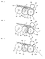
Fig. 3 is an explanatory view showing an operation of the paper-sheet feeding unit shown inFig. 1 for feeding out paper sheets; -
Fig. 4 is an explanatory view sowing the operation of the paper-sheet feeding unit shown inFig. 1 for feeding out the paper sheets, wherein a paper sheet is fed out by the feed roller from the state shown inFig. 3 ; -
Fig. 5 is an explanatory view showing the operation of the paper-sheet feeding unit shown inFig. 1 for feeding out the paper sheets, wherein the paper sheet is further fed out by the feed roller from the state shown inFig. 4 ; -
Figs. 6(a) to 6(e) are structural views showing the structure of the feed roller of the paper-sheet feeding unit shown inFig. 1 ; -
Fig. 7 is a perspective view showing the structure of the feed roller of the paper-sheet feeding unit shown inFig. 1 ; -
Fig. 8 is a perspective view showing the structure of the feed roller of the paper-sheet feeding unit shown inFig. 1 , wherein a cover member is detached from the state shown inFig. 7 ; -
Fig. 9 is a perspective view showing the feed roller of the paper-sheet feeding unit shown inFig. 1 , when the feed roller is seen in another direction; -
Fig. 10 is a perspective view showing another structure of the feed roller of the paper-sheet feeding unit in this embodiment; -
Fig. 11 is a perspective view showing still another structure of the feed roller of the paper-sheet feeding unit in this embodiment; -
Fig. 12 is a perspective view showing still another structure of the feed roller of the paper-sheet feeding unit in this embodiment; -
Fig. 13 is a perspective view showing still another structure of the feed roller of the paper-sheet feeding unit in this embodiment; -
Figs. 14(a) and 14(b) are schematic structural views schematically showing a structure of a conventional paper-sheet feeding unit; and -
Fig. 15(a) and 15(b) are schematic structural views schematically showing another structure of a conventional paper-sheet feeding unit. - An embodiment of the present invention will be described herebelow with reference to the drawings.
Figs. 1 to 9 are views showing a structure of a paper-sheet feeding unit according to this embodiment.Fig. 1 is a schematic structural view showing the paper-sheet feeding unit in this embodiment.Fig. 2A is a plan view showing a positional relationship among rollers, when the paper-sheet feeding unit shown inFig. 1 is seen from above.Fig. 2B is a view showing schematic structures of a feed roller and a delivery roller in the paper-sheet feeding unit shown inFig. 2A . InFig. 2A , a direction in which a paper sheet is fed out (feeding direction of a paper sheet) is indicated by an arrow P.Figs. 3 to 5 are explanatory views showing an operation of the paper-sheet feeding unit shown inFig. 1 for feeding out paper sheets.Figs. 6(a) to 6(e) are structural views showing the structure of the feed roller of the paper-sheet feeding unit shown inFig. 1 .Figs. 7 to 9 are perspective views showing the structure of the feed roller of the paper-sheet feeding unit shown inFig. 1 when seen in different directions. - As shown in
Fig. 1 , the paper-sheet feeding unit 1 in this embodiment includes; a storingspace 2 in which a plurality of paper sheets P are stored in a stacked state; akicker roller 30 configured to kick out a lowermost paper sheet P among the plurality of paper sheets P in a stacked state in the storingspace 2; afeed roller 10 configured to feed out the paper sheet P kicked out by thekicker roller 30; and agate roller 20 arranged to be pressed against thefeed roller 10 so as to form agate section 28 between thegate roller 20 and thefeed roller 10. In addition, in the storingspace 2, apresser member 70 is disposed above the plurality of paper sheets P in a stacked state. The plurality of paper sheets P in a stacked state are pressed by thepresser member 70 toward thekicker roller 30. - In addition, as shown in
Fig. 1 , the paper-sheet feeding unit 1 is provided with a pair ofguide members feed roller 10 is guided through a gap between the pair ofguide members guide members first transport roller 60, a firstopposite roller 62 opposed to thefirst transport roller 60, asecond transport roller 64 and a secondopposite roller 66 opposed to thesecond transport roller 64. The paper sheet P guided along the pair ofguide members first transport roller 60 and the firstopposite roller 62, and thereafter transported through a gap between thesecond transport roller 64 and the secondopposite roller 66. In addition, a paper-sheet detection sensor 68 is disposed between thefirst transport roller 60 and thesecond transport roller 64. Thus, the paper sheet P fed out from the paper-sheet feeding unit 1 is detected by the paper-sheet detection sensor 68. - The respective constituent elements of the paper-sheet feeding unit 1 are described in more detail below.
- As shown in
Fig. 1 and so on, thekicker roller 30 is located to be in contact with a surface of the lowermost paper sheet P among a plurality of paper sheets P in a stacked state in the storingspace 2. When a feeding operation of paper sheets P is carried out, thekicker roller 30 is configured to be rotated about ashaft 32 in a direction shown by the arrow inFig. 1 . Arubber member 34 is placed on a part of a circumference of an outer circumferential surface of thekicker roller 30. A paper sheet P is kicked out by therubber member 34 toward thegate section 28. As shown inFig. 2A , the threekicker rollers 30, for example, are arranged in parallel along a width direction of a paper sheet P (up and down direction inFig. 2A ). - An
auxiliary transport roller 40 is disposed on an upstream side of thekicker roller 30 in the feeding direction of a paper sheet P. When the feeding operation of paper sheets P is carried out, theauxiliary transport roller 40 is configured to be rotated about ashaft 42 in a direction shown by the arrow inFig. 1 . Theauxiliary transport roller 40 is formed of a substantially discoid roller made of plastic or metal, for example. Theauxiliary transport roller 40 is not provided with a rubber member. Theauxiliary transport roller 40 has been subjected to a so-called "D cutting", so that a part of an outer circumferential surface of theauxiliary transport roller 40 in the circumferential direction is formed as aflat part 44, When a paper sheet P is kicked out by thekicker roller 30 toward thegate section 28, a paper sheet P to be kicked out is brought into contact with or brought close to theflat part 44 of theauxiliary transport roller 40. Thus, a frictional force applied by thekicker roller 30 to the paper sheet P to be kicked out can be increased, whereby the paper sheet P can be more reliably kicked out toward thegate section 28. As shown inFig. 2A , the twoauxiliary transport rollers 40, for example, are arranged in parallel along the width direction of the paper sheet P (up and down direction inFig. 2A ). - The structure of the
feed roller 10 is described with reference toFigs. 6 to 9 .Figs. 6(a) to 6(e) are structural views showing the structure of the feed roller of the paper-sheet feeding unit 1 shown inFig. 1 . In more detail,Fig. 6(a) is a view showing structures of thefeed roller 10 and thegate roller 20 arranged to be pressed against thefeed roller 10.Fig. 6(b) is a view taken along a line A-A of thefeed roller 10 and thegate roller 20 shown inFig. 6(a). Fig. 6(c) is an enlargement view of a part surrounded by two-dot chain lines inFig. 6(a). Fig. 6(d) is a structural view showing a structure of a firstfeed roller part 14 of thefeed roller 10 shown inFig. 6(a) and so on.Fig. 6(e) is a structural view showing a structure of a secondfeed roller part 16 of thefeed roller 10 shown inFig. 6(a) and so on.Fig. 7 is a perspective view of the structure of thefeed roller 10 of the paper-sheet feeding unit 1 shown inFig. 1 .Fig. 8 is a perspective view showing a state wherein a cover has been detached from the state shown inFig. 7 .Fig. 9 is a perspective view of thefeed roller 10 of the paper-sheet feeding unit 1 shown inFig. 1 , when seen in another direction. - As shown in
Figs. 6 to 9 , thefeed roller 10 includes the substantially discoid firstfeed roller part 14 and the substantially discoid secondfeed roller part 16. The firstfeed roller part 14 and the secondfeed roller part 16 are adjacently arranged (seeFig. 6(b) ). The firstfeed roller part 14 and the secondfeed roller part 16 are concentric with each other. The firstfeed roller part 14 and the secondfeed roller part 16 are configured to be rotated integrally with each other about theshaft 12 in a direction shown by the arrow inFig. 1 . As described below, the firstfeed roller part 14 can be attached to or detached from theshaft 12, while the secondfeed roller part 16 is fixed on theshaft 12. More specifically, the firstfeed roller part 14 is removably attached to theshaft 12 by ascrew 17. - A
rubber member 14a (high friction portion) is formed on a part of a circumference of an outer circumferential surface of the firstfeed roller part 14. A paper sheet P having been delivered to thegate section 28 is fed out from thegate section 28 by therubber member 14a. A part other than therubber member 14a of the firstfeed roller part 14 functions as asupport member 15 for supporting therubber member 14a. Thesupport member 15 is made of plastic or metal, for example. In this embodiment, thesupport member 15 serves as a low friction portion having a frictional coefficient smaller than that of therubber member 14a (high friction portion). In addition, in this embodiment, therubber member 14a and thesupport member 15 serve together as an attachment member for removably attaching therubber member 14a to theshaft 12. - As shown in
Fig. 6(d) and so on, the firstfeed roller part 14 is provided with afirst cutout 14b (groove part) and asecond cutout 14c (groove part). Thefirst cutout 14b is formed to extend from a central portion of the firstfeed roller part 14 toward an outer circumferential surface thereof. While the firstfeed roller part 14 is being detached from theshaft 12, thefirst cutout 14b is used as a space through which theshaft 12 passes. On the other hand, when the firstfeed roller part 14 is fixed on theshaft 12 by thescrew 17, thesecond cutout 14c is used as a space in which thescrew 17 is accommodated. The firstfeed roller part 14 further has ascrew hole 14d into which thescrew 17 is inserted, when the firstfeed roller part 14 is fixed on theshaft 12 by thescrew 17. - In the paper-sheet feeding unit 1 in this embodiment, the
rubber member 14a of the firstfeed roller part 14 of thefeed roller 10 can be attached to or detached from theshaft 12 in a direction perpendicular to a direction in which theshaft 12 extends. To be more specific, after the paper-sheet feeding unit 1 has been used for a long period of time so that therubber member 14a of the firstfeed roper part 14 of thefeed roller 10 has been worn away, therubber member 14a should be exchanged. In this embodiment, when therubber member 14a is exchanged, thescrew 17 is detached to release the fixation of the firstfeed roller part 14 on theshaft 12, and then therubber member 14a and thesupport member 15 are detached together from theshaft 12. Specifically, in a state shown inFig. 9 , by displacing a center of thesupport member 15 from theshaft 12, theshaft 12 can pass through thefirst cutout 14b. Thus, the firstfeed roller part 14 can be detached from theshaft 12. On the other hand, when the firstfeed roller part 14 provided with anotherrubber member 14a is attached to theshaft 12, theshaft 12 firstly passes through thefirst cutout 14b to be located on the center of thesupport member 15. Thereafter, by inserting thescrew 17 into thescrew hole 14d, the firstfeed roller part 14 is fixed on theshaft 12 by thescrew 17. - As described above, in this embodiment, by moving the
support member 15 in the direction perpendicular to the direction in which theshaft 12 extends, the firstfeed roller part 14 can be detached from theshaft 12 and can be attached to theshaft 12. In order that the firstfeed roller part 14 can be attached to theshaft 12 more accurately on a central position of the rotational shaft, it is preferable to cut out a part of an outer circumferential surface of a location of theshaft 12 to which the firstfeed roller part 14 is to be attached, so that theshaft 12 has a D-shaped section (i.e., a part of the outer circumferential surface of theshaft 12 in the circumferential direction has a flat part). Due to this structure, when the firstfeed roller part 14 is detached from theshaft 12 or attached to theshaft 12, when theshaft 12 is rotated such that the flat part of theshaft 12 fits in a space betweenedge parts 14e (seeFig. 6(d) ) of thefirst cutout 14b, the firstfeed roller part 14 can be detached from theshaft 12 or attached to theshaft 12. Since a width of the space between theedge parts 14e of thefirst cutout 14b is smaller than the diameter of theshaft 12, only the portion having the smallest length in the D-shaped section of theshaft 12 is allowed to be passed through the space between theedge parts 14e of thefirst cutout 14b. - In addition, as shown in
Fig. 7 , the firstfeed roller part 14 is provided with acover member 18 that can be attached to and detached from thesupport member 15. Thefirst cutout 14b and thesecond cutout 14c of the firstfeed roller part 14 are covered with thecover member 18. Thus, when an operator conducts maintenance services on thefeed roller 10, it can be prevented that the operator's finger or the like is caught into thefirst cutout 14b or thesecond cutout 14c, causing injuries. When the firstfeed roller part 14 is fixed on theshaft 12 by thescrew 17 or when the firstfeed roller part 14 is detached from theshaft 12, as shown inFig. 8 , by detaching thecover member 18 from thesupport member 15, an operator can access thefirst cutout 14b and thesecond cutout 14c. - The second
feed roller part 16 is formed of a substantially discoid member having a frictional coefficient smaller than that of therubber member 14a of the firstfeed roller part 14. As shown inFig. 6(e) , the secondfeed roller part 16 is composed of a first outercircumferential part 16a that is an outer circumferential surface having relatively a large diameter length (a distance from the center of the feed roller 10), a second outercircumferential part 16b having a diameter length smaller than that of the first outercircumferential part 16a and twoinclined parts 16c that are disposed between the first outercircumferential part 16a and the second outercircumferential part 16b. As shown inFig. 6 , the second outercircumferential part 16b of the secondfeed roller part 16 is located on a position corresponding to therubber member 14a of the firstfeed roller part 14, and each of the twoinclined parts 16c of the secondfeed roller part 16 is located on a position corresponding to an interface between therubber member 14a of the firstfeed roller part 14 and thesupport member 15 thereof. Thus, in the secondfeed roller part 16, a distance between theinclined part 16c and the rotational center of thefeed roller 10 gradually decreases from thesupport member 15 of the firstfeed roller part 14 toward therubber member 14a thereof. Namely, the diameter length of the first outercircumferential part 16a of the secondfeed roller part 16 is substantially equal to or larger than the diameter length of thesupport member 15 of the firstfeed roller part 14. Meanwhile, the diameter length of theinclined part 16c of the secondfeed roller part 16 gradually decreases, and the diameter length of the second outercircumferential part 16b of the secondfeed roller part 16 is smaller than the diameter length of therubber member 14a of the firstfeed roller part 14. - As shown in
Fig. 6(b) and so on, in thefeed roller 10, the diameter length (the distance from the center of the feed roller 10) of the first outercircumferential part 16a of the secondfeed roller part 16 is substantially equal to or larger than the diameter length of the thesupport member 15 of the firstfeed roller part 14. On the other hand, the diameter length of eachinclined part 16c of the secondfeed roller part 16 gradually decreases, and the diameter length of the second outercircumferential part 16b of the secondfeed roller part 16 is smaller than the diameter length of therubber member 14a of the firstfeed roller part 14. - In addition, a length of the outer circumference of the
feed roller 10 is larger than a maximum length of a paper sheet P to be fed out by the paper-sheet feeding unit 1 in the feeding direction of the paper sheet P. Meanwhile, a length of therubber member 14a in the circumferential direction of the firstfeed roller part 14 of thefeed roller 10 is smaller than a minimum length of a paper sheet P to be fed out by the paper-sheet feeding unit 1 in the feeding direction of the paper sheet P. As shown inFig. 2A , the twofeed rollers 10 are arranged in parallel along the width direction of the paper sheet P (up and down direction inFig. 2A ). - The
gate roller 20 is arranged to be pressed against thefeed roller 10. More specifically, thegate roller 20 is rotatably supported on a distal end of a gate-roller support arm 27. A proximal end of the gate-roller support arm 27 is pivotally supported by ashaft 27a. A torsion spring (not shown) is disposed on theshaft 27a of the gate-roller support arm 27, so that a force is applied by the torsion spring to the gate-roller support arm 27 in a direction shown by the arrow inFig. 1 . Thus, thegate roller 20 supported by the gate-roller support arm 27 is constantly subjected to a force toward thefeed roller 10, whereby thegate roller 20 is pressed against thefeed roller 10. In addition, as described above, thegate section 28 is formed between thegate roller 20 and thefeed roller 10. Paper sheets P fed out by thefeed roller 10 are separated, one by one, by thegate section 28. - The
gate roller 20 has ashaft 22, and thegate roller 20 is rotatable about theshaft 22. As shown inFig. 6(a) and so on, arubber member 24 is formed all around an outer circumferential surface of thegate roller 20. Thegate roller 20 is equipped with a one-way clutch 26. Thegate roller 20 can be rotated by the one-way clutch 26 only in a direction (direction shown by the arrow inFig. 1 ) reverse to the feeding direction of a paper sheet P. Thus, when thefeed roller 10 is rotated in the direction reverse to the feeding direction of a paper sheet P, thegate roller 20 is rotated, along with the rotation of thefeed roller 10, in the direction reverse to the feeding direction of a paper sheet P. Meanwhile, when a paper sheet P is fed out, thegate roller 20 is not rotated in the feeding direction of a paper sheet P because of the provision of the one-way clutch 26. As shown inFig. 2A , the twogate rollers 20, for example, are arranged in parallel to be opposed to thefeed rollers 10 along the width direction of a paper sheet P (up and down direction inFig. 2A ). - As shown in
Fig. 2A ,delivery rollers 50 are arranged on both lateral sides of eachfeed roller 10. Namely, the fourdelivery rollers 50 in total are disposed in the paper-sheet feeding unit 1 in this embodiment. InFig. 1 , illustration of thedelivery rollers 50 is omitted. A size of an external diameter of eachdelivery roller 50 is substantially the same as a size of an external diameter of eachfeed roller 10. In addition, correspondingly to eachdelivery roller 50, apinch roller 51 is arranged to be pressed against an outer circumferential surface of eachdelivery roller 50. Eachpinch roller 51 is formed of a bearing or the like and is rotatable. Thepinch roller 51 is configured to be rotated along with the rotation of thecorresponding delivery roller 50. - As shown in
Fig. 2B , a rubber member 52 (high frictional section) is placed on a part of a circumference of an outer circumferential surface of eachdelivery roller 50. A part other than therubber member 52 in the outer circumferential surface functions as a base body 54 (low frictional part) made of plastic or metal. A length of therubber member 52 in the circumferential direction of eachdelivery roller 50 is larger than a length of therubber member 14a in the circumferential direction of the firstfeed roller part 14 of thefeed roller 10. Thus, after a paper sheet P has been fed out by therubber member 14a of the firstfeed roller part 14 of thefeed roller 10, the paper sheet P can be fed out by therubber member 52 of thedelivery roller 50 to a position between thefirst transport roller 60 and the firstopposite roller 62. Namely, after having been fed out, the paper sheet P can be reliably transported. - Next, an operation of the paper-sheet feeding unit 1 as structured above, specifically a feeding method of a paper sheet P by the paper-sheet feeding unit 1, is described with reference to
Figs. 3 to 5 . - As shown in
Fig. 1 and so on, when a plurality of paper sheets P are stored in the storingspace 2 in a stacked state, the lowermost paper sheet P is kicked out by thekicker roller 30. To be specific, as shown inFig. 3 , the lowermost paper sheet P is kicked out by therubber member 34 provided on thekicker roller 30 toward thegate section 28. When thekicker roller 30 kicks out the paper sheet P toward thegate section 28, the paper sheet P to be kicked out is brought into contact with or brought close to theflat part 44 of theauxiliary transport roller 40. Thus, a frictional force applied by thekicker roller 30 to the paper sheet P to be kicked out can be increased, so that the paper sheet P can be more reliably kicked out toward thegate section 28. In addition, as shown inFig. 3 , when therubber member 14a of the firstfeed roller part 14 of thefeed roller 10 is opposed to thegate roller 20, thekicker roller 30 is configured to kick out the paper sheet P toward thegate section 28. Thus, the paper sheet P having been delivered to thegate section 28 can be promptly fed out by thefeed roller 10, and wear of therubber member 24 of thegate roller 20 can be restrained. - As shown in
Fig. 4 , the paper sheet P having been delivered to thegate section 28 is fed out, one by one, by therubber member 14a of the firstfeed roller part 14 of thefeed roller 10. At this time, thegate roller 20 is maintained to stop. Then, as shown inFig. 5 , after the paper sheet P has been completely fed out by thefeed roller 10 and a predetermined period of time has elapsed, a succeeding paper sheet p is kicked out by thekicker roller 30 toward thegate section 28. - In this embodiment, since the
rubber member 14a is placed on a part of the circumference of the outer circumferential surface of the firstfeed roller part 14 of thefeed roller 10, instead of being placed all around the same, installation of a torque limiter on thegate roller 20 can be omitted. That is to say, suppose that therubber member 14a is placed all around the outer circumferential surface of the firstfeed roller part 14 of thefeed roller 10. In this case, unless a torque limiter is disposed on thegate roller 20, thegate roller 20 is not rotated along with the rotation of thefeed roller 10 but is stopped, although thefeed roller 10 is rotated when no paper sheet P exists in thegate section 28. Thus, there occurs a problem that a certain point in therubber member 24 of thegate roller 20 is intensively worn away. On the other hand, in this embodiment, therubber member 14a is placed on a part of the circumference of the outer circumferential surface of the firstfeed roller part 14 of thefeed roller 10. In this case, in the feeding operation of a paper sheet P, when therubber member 14a of the firstfeed roller part 14 of thefeed roller 10 and therubber member 24 of thegate roller 20 are opposed to each other, a paper sheet P to be fed out by thefeed roller 10 exists between therubber members rubber members rubber member 24 of thegate roller 20 can be restrained, without installation of a torque limiter on thegate roller 20. - In addition, in this embodiment, as described above, the length of the outer circumference of the
feed roller 10 is larger than the maximum length of a paper sheet P to be fed out by the paper-sheet feeding unit 1 in the feeding direction of the paper sheet P. Simultaneously, the length of therubber member 14a in the circumferential direction of the firstfeed roller part 14 of thefeed roller 10 is smaller than the minimum length of a paper sheet P to be fed out by the paper-sheet feeding unit 1 in the feeding direction of the paper sheet P. Thus, there can be prevented that two or more paper sheets P are fed out at once in a chained state or in an overlapped state by therubber member 14a. - In addition, when the paper-sheet feeding unit 1 is used for a long period of time, the
rubber member 14a of the firstfeed roller part 14 of thefeed roller 10 is worn away. When therubber member 14a is worn away so that the diameter length thereof (distance from the center of the feed roller 10) becomes smaller than the diameter length of the second outercircumferential part 16b of the secondfeed roller part 16 and/or the diameter length of theinclined parts 16c thereof, thegate section 28 is formed between the secondfeed roller part 16 and thegate roller 20. As described above, since the distance between theinclined part 16c and the rotational center of thefeed roller 10 gradually decreases from thesupport member 15 of the firstfeed roller part 14 toward therubber member 14a thereof, thegate roller 20 is smoothly pressed against thefeed roller 10, so as to prevent thegate roller 20 from bounding. In other words, unless there is the secondfeed roller part 16, when therubber member 14a of the firstfeed roller part 14 is worn away, a step is formed between therubber member 14a of the firstfeed roller part 14 and the outer circumference of thesupport member 15 thereof. Because of the step, thegate roller 20 may bound against thefeed roller 10, resulting in adverse affect on the feeding performance of a paper sheet P. However, due to the provision of the secondfeed roller part 16, even when therubber member 14a of the firstfeed roller part 14 is worn away so that a step is formed between therubber member 14a of the firstfeed roller part 14 and the outer circumference of thesupport member 15 thereof, theinclined parts 16c of the secondfeed roller part 16 compensate for such a step. Therefore, there is no possibility that thegate roller 20 bounds against thefeed roller 10. - In addition, in this embodiment, when the paper-sheet feeding unit 1 is in a standby condition after the feeding operation of a paper sheet P by the paper-sheet feeding unit 1 has been finished, when the
feed roller 10 is rotated in the direction reverse to the feeding direction of a paper sheet P, thegate roller 20 is rotated, along with the rotation of thefeed roller 10, in the direction reverse to the feeding direction of a paper sheet P. Owing to this operation, a location of thegate roller 20, at which thegate roller 20 is in contact with thefeed roller 10, can be changed. Thus, it can be prevented that a certain point in therubber member 24 of thegate roller 20 is intensively worn away (uneven wear). - As described above, according to the paper-sheet feeding unit 1 in this embodiment, in the
feed roller 10, therubber member 14a is placed on a part of the circumference of the outer circumferential surface of the firstfeed roller part 14, and the part other than therubber member 14a of the outer circumferential surface of thefeed roller 10 is provided with thesupport member 15, which has a frictional coefficient smaller than that of therubber member 14a, and the first outercircumferential part 16a of the secondfeed roller part 16. In addition, thegate roller 20 is arranged to be pressed against the outer circumferential surface of thefeed roller 10. Since therubber member 14a is placed on a part of the circumference of the outer circumferential surface of thefeed roller 10, instead of being placed all around the outer circumferential surface of thefeed roller 10, installation of a torque limited on thegate roller 20 can be omitted. Thus, reduction in cost and size can be achieved. Moreover, since thegate roller 20 is arranged to be pressed against the outer circumferential surface of thefeed roller 10, plural kinds of paper sheets having different thicknesses and/or stiffnesses can be properly fed out. - In addition, according to the paper-sheet feeding unit 1 in this embodiment, the second
feed roller part 16 of thefeed roller 10 has theinclined parts 16c each of which is located at a position near the interface between the therubber member 14a (high friction portion) of the firstfeed roller part 14 and the support member 15 (low friction portion) thereof, The distance between theinclined part 16c and the rotational center of thefeed roller 10 gradually decreases from thesupport member 15 toward therubber member 14a. Thus, even after the paper-sheet feeding unit 1 has been used for a long period of time so that therubber member 14a of the firstfeed roller part 14 has been worn away, thegate roller 20 can be prevented from bounding against thefeed roller 10. - In addition, according to the paper-sheet feeding unit 1 in this embodiment, the
rubber member 14a of the firstfeed roller part 14 of thefeed roller 10 can be attached to or detached from theshaft 12 of thefeed roller 10 in the direction perpendicular to the direction in which theshaft 12 extends, Thus, even after the paper-sheet feeding unit 1 has been used for a long period of time so that therubber member 14a of the firstfeed roller part 14 has been worn away, therubber member 14a can be easily exchanged. Namely, when the rubber member disposed on the outer circumferential surface of the feed roller is worn away, it has been conventionally needed to detach the feed roller itself from the rotational shaft by moving the feed roller in the axial direction of the rotational shaft, and then to attach to the rotational shaft the feed roller to which a new rubber member has been attached. On the other hand, in this embodiment, therubber member 14a can be exchanged without detaching thefeed roller 10 itself from theshaft 12 by moving thefeed roller 10 in the direction in which theshaft 12 extends. Thus, it is easy to conduct maintenance services on therubber 14a (high friction portion) and reduction in maintenance cost can be achieved. - The paper-sheet feeding unit in this embodiment is not limited to the above embodiment, but can be variously modified.
- For example, in the paper-sheet feeding unit 1 shown in
Fig. 1 and so on, thegate section 28 is formed by pressing thegate roller 20 against thefeed roller 10, and paper sheets P, which are fed out by thefeed roller 10, are separated, one by one, by thegate section 28. However, a gate member for forming the gate section is not limited to thegate roller 20. A structure other than a roller, specifically, e.g., a pad may be used as the gate member for forming the gate section. - In addition, the
feed roller 10 is not limited to the split-type roller as shown inFig. 6 , which is composed of the firstfeed roller part 14 and the secondfeed roller part 16. An integral-type roller may be used as the feed roller, In a case where an integral-type roller is used as the feed roller, when a rubber member disposed on the outer circumferential surface of the feed roller is worn away, the feed roller is detached from the rotational shaft by moving the feed roller itself in the axial direction of the rotational shaft, and then the feed roller to which a new rubber member has been attached is attached to the rotational shaft. - In a case where the
feed roller 10 is of a split-type, thefeed roller 10 is not limited to a roller in which therubber member 14a can be attached to or detached from theshaft 12 of thefeed roller 10 in the direction perpendicular to the direction in which theshaft 12 extends. The feed roller may be a roller in which the rubber member (high friction portion) can be attached to or detached from the base body of the feed roller fixed on the rotational shaft in the direction in which the rotational shaft extends. - Herebelow, various structural examples of the spilt-type feed roller will be described with reference to
Figs. 10 to 13. Figs. 10 to 13 are perspective views respectively showing other structures of the feed roller of the paper-sheet feeding unit 1 in this embodiment. - In a
feed roller 110 shown inFig. 10 , a substantially discoid base body 141 made of plastic or metal is disposed on ashaft 112. Thebase body 114 has acutout 114a in which arubber member 116 can be fitted. Therubber member 116 can be attached to thecutout 114a of thebase body 114 by ascrew 118 or the like, Namely, in thefeed roller 110 shown inFig. 10 , the rubber member 116 (high friction portion) can be attached to or detached from thebase body 114 of thefeed roller 110 fixed on theshaft 112 in the direction perpendicular to the direction in which theshaft 112 extends. - In a
feed roller 120 shown inFig. 11 , a substantiallydiscoid base body 124 made of plastic or metal is disposed on ashaft 122. Anadditional disc 134 of the same structure as that of the secondfeed roller part 16 shown inFig. 6 is joined to thefirst base body 124, In addition, thebase body 124 has acutout 124a in which anattachment member 126 can be fitted. Theattachment member 126 is composed of arubber member 130 and asupport member 128 that supports therubber member 130, Theattachment member 126 can be attached to thecutout 124a of thebase body 124 by ascrew 132 or the like, Namely, in thefeed roller 120 shown inFig. 11 , the rubber member 130 (high friction portion) can be attached to or detached from thebase body 124 of thefeed roller 120 fixed on theshaft 122 in the direction perpendicular to the direction in which theshaft 122 extends. - In a
feed roller 140 shown inFig. 12 , anattachment member 146, which is composed of arubber member 150 and asupport member 148 that supports therubber member 150, can be directly attached to ashaft 142. More specifically, theshaft 142 has acutout 142a in which theattachment member 146 can be fitted, so that theattachment member 146 can be attached to thecutout 142a of theshaft 142. In addition, theshaft 142 is provided with anadditional disc 144 of the same structure as that of the secondfeed roller part 16 shown inFig. 6 . Namely, in thefeed roller 140 shown inFig. 12 , the rubber member 150 (high friction portion) can be attached to or detached from theshaft 142 in the direction perpendicular to the direction in which theshaft 142 extends. - Also in a
feed roller 160 shown inFig. 13 , anattachment member 164, which is composed of arubber member 168 and asupport member 166 that supports therubber member 168, can be directly attached to ashaft 162. More specifically, theshaft 162 has ascrew hole 162a, so that theattachment member 164 can be attached to the position of thescrew hole 162a by a screw, not shown. Namely, in thefeed roller 160 shown inFig. 13 , the rubber member 168 (high friction portion) can be attached to or detached from theshaft 162 in the direction perpendicular to the direction in which theshaft 162 extends. - As described above, in the
respective feed rollers Figs. 10 to 13 , the rubber member of the feed roller can be attached to or detached from the shaft of the feed roller or the base body provided on the shaft, in the direction perpendicular to the direction in which the shaft extends. Thus, even after the paper-sheet feeding unit 1 has been used for a long period of time so that the rubber member of the feed roller has been worn away, the rubber member can be exchanged without detaching the feed roller itself from the shaft by moving the feed roller in the direction in which the shaft extends. Therefore, it is easy to conduct maintenance services on the rubber member (high friction portion), and reduction in maintenance cost can be achieved.
Claims (19)
- A paper-sheet feeding unit configured to feed out, one by one, paper sheets in a stacked state, the paper-sheet feeding unit comprising:a feed roller configured to be rotated when feeding out the paper sheet, the feed roller having a high friction portion placed on a part of a circumference of an outer circumferential surface thereof, and a low friction portion placed on a location of the outer circumferential surface thereof other than the high friction portion, the low friction portion having a frictional coefficient smaller than that of the high friction portion; anda gate member arranged to be pressed against the outer circumferential surface of the feed roller, the gate member constituting a gate section configured to separate, one by one, the paper sheets fed out by the feed roller.
- The paper-sheet feeding unit according to claim 1, wherein
a length of an outer circumference of the feed roller is larger than a length of the paper sheet to be fed out by the paper-sheet feeding unit, in a direction in which the paper sheet is fed out. - The paper-sheet feeding unit according to claim 1 or 2, wherein
a length of the high friction portion in a circumferential direction of the feed roller is smaller than a minimum length of the paper sheet to be fed out by the paper-sheet feeding unit, in a direction in which the paper sheet is fed out. - The paper-sheet feeding unit according to any one of claims 1 to 3, further comprising
a delivery mechanism disposed on an upstream side of the feed roller in the direction in which the paper sheet is fed out, the delivery mechanism being configured to be brought into contact with a surface of the foremost paper sheet among the plurality of paper sheets in a stacked state so as to deliver the paper sheet to the gate section,
wherein the delivery mechanism is configured to deliver the paper sheet to the gate section, when the high friction portion of the feed roller is opposed to the gate member. - The paper-sheet feeding unit according to any one of claims 1 to 4, wherein
an inclined part having a frictional coefficient smaller than that of the high friction portion is disposed on a lateral side of the feed roller at a position of an interface between the high friction portion and the low friction portion, with a distance between the inclined part and a rotational center of the feed roller gradually decreasing from the low friction portion toward the high friction portion. - The paper-sheet feeding unit according to any one of claims 1 to 5, wherein
the gate member includes a gate roller having a friction portion on an outer circumferential surface thereof, and a one-way clutch disposed on the gate roller,
the gate roller is configured to be rotated by the one-way clutch only in a direction reverse to a direction in which the paper sheet is fed out, and
when the feed roller is rotated in the direction reverse to the direction in which the paper sheet is fed out, the gate roller is configured to be rotated, along with the rotation of the feed roller, in the direction reverse to the direction in which the paper sheet is fed out. - The paper-sheet feeding unit according to any one of claims 1 to 6, further comprising
a rotational shaft rotatably supporting the feed roller, wherein the high friction portion of the feed roller is attachable to and detachable from a base body of the feed roller fixed on the rotational shaft or the rotational shaft itself, in a direction perpendicular to a direction in which the rotational shaft extends. - A paper-sheet feeding unit configured to feed out, one by one, paper sheets in a stacked state, the paper-sheet feeding unit comprising:a feed roller configured to be rotated when feeding out the paper sheet, the feed roller having a high friction portion placed on a part of a circumference of an outer circumferential surface thereof, and a low friction portion placed on a location of the outer circumferential surface thereof other than the high friction portion, the low friction portion having a frictional coefficient smaller than that of the high friction portion;a gate member disposed opposite to the feed roller, the gate member constituting a gate section configured to separate, one by one, the paper sheets fed out by the feed roller; anda rotational shaft rotatably supporting the feed roller;wherein the high friction portion of the feed roller is attachable to and detachable from a base body of the feed roller fixed on the rotational shaft, in a direction perpendicular to a direction in which the rotational shaft extends.
- The paper-sheet feeding unit according to claim 8, wherein
there is provided an attachment member that is attachable to and detachable from the base body of the feed roller in the direction perpendicular to the direction in which the rotational shaft extends, and
the high friction portion is included in the attachment member. - The paper-sheet feeding unit according to claim 9, wherein
the attachment member has a support member supporting the high friction portion, and
the support member is attachable to and detachable from the base body of the feed roller in the direction perpendicular to the direction in which the rotational shaft extends. - The paper-sheet feeding unit according to claim 9 or 10, wherein
the attachment member is provided with a groove part through which the rotational shaft passes while the attachment member is being attached to or detached from the base body of the feed roller. - A paper-sheet feeding unit configured to feed out, one by one, paper sheets in a stacked state, the paper-sheet feeding unit comprising:a feed roller configured to be rotated when feeding out the paper sheet, the feed roller having a high friction portion placed on a part of a circumference of an outer circumferential surface thereof, and a low friction portion placed on a location of the outer circumferential surface thereof other than the high friction portion, the low friction portion having a frictional coefficient smaller than that of the high friction portion;a gate member disposed opposite to the feed roller, the gate member constituting a gate section configured to separate, one by one, the paper sheets fed out by the feed roller; anda rotational shaft rotatably supporting the feed roller;wherein the high friction portion of the feed roller is attachable to and detachable from the rotational shaft in a direction perpendicular to a direction in which the rotational shaft extends.
- The paper-sheet feeding unit according to claim 12, wherein
there is provided an attachment member that is attachable to and detachable from the rotational shaft in the direction perpendicular to the direction in which the rotational shaft extends, and
the high friction portion is included in the attachment member. - The paper-sheet feeding unit according to claim 13, wherein
the attachment member has a support member supporting the high friction portion, and
the support member is attachable to and detachable from the rotational shaft in the direction perpendicular to the direction in which the rotational shaft extends. - The paper-sheet feeding unit according to claim 13 or 14, wherein
the attachment member is provided with a groove part through which the rotational shaft passes while the attachment member is being attached to or detached from the rotational shaft. - The paper-sheet feeding unit according to claim 15 wherein
the rotational shaft has a portion having a D-shaped section that has been formed by cutting-off of a part of an outer circumferential surface of the rotational shaft, and
the groove part has a portion having a width smaller than a diameter of the rotational shaft. - The paper-sheet feeding unit according to any one of claims 11, 15 and 16, wherein
a cover member for closing the groove part is removably disposed on the attachment member. - The paper-sheet feeding unit according to any one of claims 1 to 17, wherein:there are provided a delivery roller having an external diameter substantially the same as an external diameter of the feed roller on a lateral side of the feed roller, and a pinch roller configured to be rotated while being pressed against an outer circumferential surface of the delivery roller; andthe delivery roller is configured to be rotated when feeding out the paper sheet, the delivery roller having a high friction portion placed on a part of a circumference of an outer circumferential surface thereof, and a low friction portion placed on a location of the outer circumferential surface thereof other than the high friction portion, the low friction portion having a frictional coefficient smaller than that of the high friction portion.
- The paper-sheet feeding unit according to claim 18, wherein
a length of the high friction portion in a circumferential direction of the delivery roller is larger than a length of the high friction portion in a circumferential direction of the feed roller.
Applications Claiming Priority (1)
| Application Number | Priority Date | Filing Date | Title |
|---|---|---|---|
| JP2012130971A JP6000669B2 (en) | 2012-06-08 | 2012-06-08 | Paper sheet feeding device |
Publications (2)
| Publication Number | Publication Date |
|---|---|
| EP2671827A2 true EP2671827A2 (en) | 2013-12-11 |
| EP2671827A3 EP2671827A3 (en) | 2014-12-24 |
Family
ID=48613443
Family Applications (1)
| Application Number | Title | Priority Date | Filing Date |
|---|---|---|---|
| EP13170999.0A Withdrawn EP2671827A3 (en) | 2012-06-08 | 2013-06-07 | Paper-sheet feeding unit |
Country Status (4)
| Country | Link |
|---|---|
| US (2) | US9340381B2 (en) |
| EP (1) | EP2671827A3 (en) |
| JP (1) | JP6000669B2 (en) |
| CN (1) | CN103482397B (en) |
Cited By (1)
| Publication number | Priority date | Publication date | Assignee | Title |
|---|---|---|---|---|
| CN113400820A (en) * | 2021-05-31 | 2021-09-17 | 凌建芳 | Printer paper feed dustproof mechanism |
Families Citing this family (12)
| Publication number | Priority date | Publication date | Assignee | Title |
|---|---|---|---|---|
| JP6000669B2 (en) * | 2012-06-08 | 2016-10-05 | グローリー株式会社 | Paper sheet feeding device |
| US9216868B1 (en) * | 2014-09-02 | 2015-12-22 | Foxlink Image Technology Co., Ltd. | Paper staging mechanism |
| JP6435802B2 (en) * | 2014-11-19 | 2018-12-12 | 日立金属株式会社 | roller |
| JP6414484B2 (en) | 2015-02-27 | 2018-10-31 | ブラザー工業株式会社 | Transport device |
| JP6380164B2 (en) | 2015-02-27 | 2018-08-29 | ブラザー工業株式会社 | Transport device |
| JP6447237B2 (en) * | 2015-02-27 | 2019-01-09 | ブラザー工業株式会社 | Transport device |
| CN105775871B (en) * | 2016-04-26 | 2018-07-03 | 北京石油化工学院 | Conveyor type bank note automatic sorting device |
| ES2942186T3 (en) * | 2016-09-22 | 2023-05-30 | Giesecke & Devrient Currency Technology Gmbh | Method for selecting sheet material |
| JP6874326B2 (en) * | 2016-10-27 | 2021-05-19 | ブラザー工業株式会社 | Sheet transfer device |
| JP7164830B2 (en) * | 2018-03-26 | 2022-11-02 | セイコーエプソン株式会社 | Media feeding device, image reading device |
| TWI804835B (en) * | 2021-03-30 | 2023-06-11 | 虹光精密工業股份有限公司 | Paper separating roller, paper transmitting device, and office machine using the same |
| CN113771431A (en) * | 2021-09-07 | 2021-12-10 | 宁波荣华数码印刷设备有限公司 | Indentation machine and indentation cementing machine |
Citations (4)
| Publication number | Priority date | Publication date | Assignee | Title |
|---|---|---|---|---|
| JP3703598B2 (en) | 1997-03-21 | 2005-10-05 | グローリー工業株式会社 | Paper sheet feeding device |
| WO2008072317A1 (en) | 2006-12-13 | 2008-06-19 | Glory Ltd. | Paper sheet advancing device |
| JP4680302B2 (en) | 2007-02-08 | 2011-05-11 | グローリー株式会社 | Bill feeding device |
| JP4846716B2 (en) | 2005-06-14 | 2011-12-28 | グローリー株式会社 | Paper sheet feeding device |
Family Cites Families (27)
| Publication number | Priority date | Publication date | Assignee | Title |
|---|---|---|---|---|
| JPS59118630A (en) * | 1982-12-27 | 1984-07-09 | Toshiba Corp | Paper-sheet taking-out apparatus |
| KR890000910B1 (en) * | 1984-06-29 | 1989-04-13 | 가부시기가이샤 히다찌세이사꾸쇼 | Paper conveying and separating device |
| JPH0475934A (en) * | 1990-07-13 | 1992-03-10 | Canon Inc | Roller |
| JPH04129935A (en) * | 1990-09-19 | 1992-04-30 | Omron Corp | Fuzzy control device for paper sheet feed adjustment |
| US5297786A (en) * | 1991-11-06 | 1994-03-29 | Roberts Systems, Inc. | Cleated wheel assembly and method of separating a sheet using a cleated wheel assembly |
| JP2913999B2 (en) * | 1992-04-24 | 1999-06-28 | 株式会社日立製作所 | Paper sheet separation device |
| JPH06301646A (en) | 1993-04-09 | 1994-10-28 | Mitsubishi Electric Corp | Security retention method |
| JP3319240B2 (en) * | 1995-08-28 | 2002-08-26 | 富士電機株式会社 | Single-sheet feeding device for batch input sheets |
| JP3728088B2 (en) * | 1998-01-30 | 2005-12-21 | キヤノン株式会社 | Sheet feeding roller, sheet feeding apparatus, and image forming apparatus |
| JP3560223B2 (en) * | 1998-09-17 | 2004-09-02 | 株式会社日立製作所 | Paper sheet separation and feeding device |
| JP2000103532A (en) * | 1998-09-30 | 2000-04-11 | Fujitsu Ltd | Pick roller and paper feeder |
| JP2002053234A (en) * | 2000-08-09 | 2002-02-19 | Oki Electric Ind Co Ltd | Paper sending device |
| US6798899B2 (en) * | 2001-01-04 | 2004-09-28 | Cummins-Allison Corp. | Document feeding method and apparatus |
| DE10105521A1 (en) * | 2001-02-07 | 2002-08-08 | Giesecke & Devrient Gmbh | Device and method for separating sheet material |
| US7140607B2 (en) * | 2002-10-18 | 2006-11-28 | Diebold Self-Service Systems Division Of Diebold, Incorporated | Cash dispensing automated banking machine with note unstacking and validation |
| CN1714363B (en) | 2002-10-18 | 2012-12-19 | 迪布尔特有限公司 | automated banking machine |
| CN1839081B (en) | 2003-03-10 | 2010-09-15 | 迪布尔特有限公司 | Cash dispensing automated banking machine and method |
| CN100507958C (en) | 2003-10-17 | 2009-07-01 | 迪布尔特有限公司 | Cash dispensing automated banking machine with note unstacking and validation |
| CN1990365A (en) | 2005-12-29 | 2007-07-04 | 广州广电运通金融电子股份有限公司 | Friction wheel for laminated medium conveying means and conveying means thereof |
| JP2010173810A (en) * | 2009-01-30 | 2010-08-12 | Canon Finetech Inc | Recording medium feeding apparatus and image forming apparatus |
| JP5341169B2 (en) * | 2009-02-19 | 2013-11-13 | グローリー株式会社 | Paper sheet counting device |
| CN102205913B (en) | 2010-03-31 | 2013-04-17 | 珠海赛纳打印科技股份有限公司 | Paper-feeding roller device |
| JP5659656B2 (en) * | 2010-09-22 | 2015-01-28 | 富士ゼロックス株式会社 | Recording medium conveying apparatus and image forming apparatus |
| JP5818574B2 (en) * | 2011-08-22 | 2015-11-18 | キヤノン株式会社 | Sheet feeding apparatus and image forming apparatus |
| JP6000669B2 (en) * | 2012-06-08 | 2016-10-05 | グローリー株式会社 | Paper sheet feeding device |
| CN102867359B (en) * | 2012-09-21 | 2014-10-22 | 广州广电运通金融电子股份有限公司 | Self-service financial equipment and currency note separating device and currency note separating method of self-service financial equipment |
| KR101761656B1 (en) * | 2014-06-12 | 2017-07-26 | 노틸러스효성 주식회사 | A media separation apparatus of ATM |
-
2012
- 2012-06-08 JP JP2012130971A patent/JP6000669B2/en active Active
-
2013
- 2013-06-07 EP EP13170999.0A patent/EP2671827A3/en not_active Withdrawn
- 2013-06-07 US US13/912,250 patent/US9340381B2/en active Active
- 2013-06-08 CN CN201310227288.1A patent/CN103482397B/en active Active
-
2016
- 2016-03-09 US US15/064,994 patent/US9533847B2/en active Active
Patent Citations (4)
| Publication number | Priority date | Publication date | Assignee | Title |
|---|---|---|---|---|
| JP3703598B2 (en) | 1997-03-21 | 2005-10-05 | グローリー工業株式会社 | Paper sheet feeding device |
| JP4846716B2 (en) | 2005-06-14 | 2011-12-28 | グローリー株式会社 | Paper sheet feeding device |
| WO2008072317A1 (en) | 2006-12-13 | 2008-06-19 | Glory Ltd. | Paper sheet advancing device |
| JP4680302B2 (en) | 2007-02-08 | 2011-05-11 | グローリー株式会社 | Bill feeding device |
Cited By (1)
| Publication number | Priority date | Publication date | Assignee | Title |
|---|---|---|---|---|
| CN113400820A (en) * | 2021-05-31 | 2021-09-17 | 凌建芳 | Printer paper feed dustproof mechanism |
Also Published As
| Publication number | Publication date |
|---|---|
| CN103482397B (en) | 2018-01-02 |
| CN103482397A (en) | 2014-01-01 |
| JP2013252956A (en) | 2013-12-19 |
| EP2671827A3 (en) | 2014-12-24 |
| US20130328260A1 (en) | 2013-12-12 |
| JP6000669B2 (en) | 2016-10-05 |
| US9533847B2 (en) | 2017-01-03 |
| US20160229649A1 (en) | 2016-08-11 |
| US9340381B2 (en) | 2016-05-17 |
Similar Documents
| Publication | Publication Date | Title |
|---|---|---|
| US9533847B2 (en) | Paper-sheet feeding unit | |
| US9016611B2 (en) | Medium storing and advancing apparatus | |
| JP3560223B2 (en) | Paper sheet separation and feeding device | |
| JP6189124B2 (en) | Paper sheet stacking mechanism and paper sheet processing apparatus | |
| JP2011079596A (en) | Paper sheet separating carrying device | |
| WO2009150924A1 (en) | Device for containing and discharging paper sheets or the like | |
| JP2009143688A (en) | Sheet material feeding device | |
| JP2011241011A (en) | Sheet feeding device | |
| WO2008072317A1 (en) | Paper sheet advancing device | |
| JP5745915B2 (en) | Printer device | |
| JP2019101676A (en) | Paper storage apparatus and paper processing apparatus | |
| JP5846266B2 (en) | Sheet feeding device | |
| JP5716405B2 (en) | Sheet processing device | |
| HK1190376B (en) | Paper-sheet feeding unit | |
| HK1190376A (en) | Paper-sheet feeding unit | |
| JP6353137B2 (en) | Paper sheet processing equipment | |
| JP3928757B2 (en) | Media separation mechanism | |
| JP2008178993A (en) | Printing unit | |
| WO2016199314A1 (en) | Bill counter | |
| JP5926646B2 (en) | Passbook issuing device | |
| JP2004142870A (en) | Image forming device | |
| JP2016062228A (en) | Tape take-up type bill reflux device and reflux type bill processing device | |
| JPH10279088A (en) | Paper tray for printer | |
| JP2011096129A (en) | Processing apparatus for paper sheets | |
| JP2008137763A (en) | Paper feeding device and image forming device |
Legal Events
| Date | Code | Title | Description |
|---|---|---|---|
| PUAI | Public reference made under article 153(3) epc to a published international application that has entered the european phase |
Free format text: ORIGINAL CODE: 0009012 |
|
| AK | Designated contracting states |
Kind code of ref document: A2 Designated state(s): AL AT BE BG CH CY CZ DE DK EE ES FI FR GB GR HR HU IE IS IT LI LT LU LV MC MK MT NL NO PL PT RO RS SE SI SK SM TR |
|
| AX | Request for extension of the european patent |
Extension state: BA ME |
|
| RIC1 | Information provided on ipc code assigned before grant |
Ipc: B65H 3/52 20060101ALI20140729BHEP Ipc: B65H 3/06 20060101AFI20140729BHEP |
|
| PUAL | Search report despatched |
Free format text: ORIGINAL CODE: 0009013 |
|
| AK | Designated contracting states |
Kind code of ref document: A3 Designated state(s): AL AT BE BG CH CY CZ DE DK EE ES FI FR GB GR HR HU IE IS IT LI LT LU LV MC MK MT NL NO PL PT RO RS SE SI SK SM TR |
|
| AX | Request for extension of the european patent |
Extension state: BA ME |
|
| RIC1 | Information provided on ipc code assigned before grant |
Ipc: B65H 3/06 20060101AFI20141119BHEP Ipc: B65H 3/52 20060101ALI20141119BHEP |
|
| 17P | Request for examination filed |
Effective date: 20150624 |
|
| RBV | Designated contracting states (corrected) |
Designated state(s): AL AT BE BG CH CY CZ DE DK EE ES FI FR GB GR HR HU IE IS IT LI LT LU LV MC MK MT NL NO PL PT RO RS SE SI SK SM TR |
|
| 17Q | First examination report despatched |
Effective date: 20180105 |
|
| GRAP | Despatch of communication of intention to grant a patent |
Free format text: ORIGINAL CODE: EPIDOSNIGR1 |
|
| INTG | Intention to grant announced |
Effective date: 20181029 |
|
| STAA | Information on the status of an ep patent application or granted ep patent |
Free format text: STATUS: THE APPLICATION IS DEEMED TO BE WITHDRAWN |
|
| 18D | Application deemed to be withdrawn |
Effective date: 20190312 |