EP2670019A1 - Shovel - Google Patents
Shovel Download PDFInfo
- Publication number
- EP2670019A1 EP2670019A1 EP12739049.0A EP12739049A EP2670019A1 EP 2670019 A1 EP2670019 A1 EP 2670019A1 EP 12739049 A EP12739049 A EP 12739049A EP 2670019 A1 EP2670019 A1 EP 2670019A1
- Authority
- EP
- European Patent Office
- Prior art keywords
- charge
- value
- capacitor
- energy storage
- electrical energy
- Prior art date
- Legal status (The legal status is an assumption and is not a legal conclusion. Google has not performed a legal analysis and makes no representation as to the accuracy of the status listed.)
- Withdrawn
Links
Images


Classifications
-
- H—ELECTRICITY
- H02—GENERATION; CONVERSION OR DISTRIBUTION OF ELECTRIC POWER
- H02J—CIRCUIT ARRANGEMENTS OR SYSTEMS FOR SUPPLYING OR DISTRIBUTING ELECTRIC POWER; SYSTEMS FOR STORING ELECTRIC ENERGY
- H02J7/00—Circuit arrangements for charging or depolarising batteries or for supplying loads from batteries
- H02J7/14—Circuit arrangements for charging or depolarising batteries or for supplying loads from batteries for charging batteries from dynamo-electric generators driven at varying speed, e.g. on vehicle
-
- E—FIXED CONSTRUCTIONS
- E02—HYDRAULIC ENGINEERING; FOUNDATIONS; SOIL SHIFTING
- E02F—DREDGING; SOIL-SHIFTING
- E02F9/00—Component parts of dredgers or soil-shifting machines, not restricted to one of the kinds covered by groups E02F3/00 - E02F7/00
- E02F9/08—Superstructures; Supports for superstructures
- E02F9/10—Supports for movable superstructures mounted on travelling or walking gears or on other superstructures
- E02F9/12—Slewing or traversing gears
- E02F9/121—Turntables, i.e. structure rotatable about 360°
- E02F9/128—Braking systems
-
- E—FIXED CONSTRUCTIONS
- E02—HYDRAULIC ENGINEERING; FOUNDATIONS; SOIL SHIFTING
- E02F—DREDGING; SOIL-SHIFTING
- E02F9/00—Component parts of dredgers or soil-shifting machines, not restricted to one of the kinds covered by groups E02F3/00 - E02F7/00
- E02F9/20—Drives; Control devices
- E02F9/2058—Electric or electro-mechanical or mechanical control devices of vehicle sub-units
- E02F9/2091—Control of energy storage means for electrical energy, e.g. battery or capacitors
-
- E—FIXED CONSTRUCTIONS
- E02—HYDRAULIC ENGINEERING; FOUNDATIONS; SOIL SHIFTING
- E02F—DREDGING; SOIL-SHIFTING
- E02F9/00—Component parts of dredgers or soil-shifting machines, not restricted to one of the kinds covered by groups E02F3/00 - E02F7/00
- E02F9/20—Drives; Control devices
- E02F9/2058—Electric or electro-mechanical or mechanical control devices of vehicle sub-units
- E02F9/2095—Control of electric, electro-mechanical or mechanical equipment not otherwise provided for, e.g. ventilators, electro-driven fans
-
- E—FIXED CONSTRUCTIONS
- E02—HYDRAULIC ENGINEERING; FOUNDATIONS; SOIL SHIFTING
- E02F—DREDGING; SOIL-SHIFTING
- E02F9/00—Component parts of dredgers or soil-shifting machines, not restricted to one of the kinds covered by groups E02F3/00 - E02F7/00
- E02F9/20—Drives; Control devices
- E02F9/22—Hydraulic or pneumatic drives
- E02F9/2217—Hydraulic or pneumatic drives with energy recovery arrangements, e.g. using accumulators, flywheels
-
- H—ELECTRICITY
- H01—ELECTRIC ELEMENTS
- H01M—PROCESSES OR MEANS, e.g. BATTERIES, FOR THE DIRECT CONVERSION OF CHEMICAL ENERGY INTO ELECTRICAL ENERGY
- H01M10/00—Secondary cells; Manufacture thereof
- H01M10/42—Methods or arrangements for servicing or maintenance of secondary cells or secondary half-cells
- H01M10/44—Methods for charging or discharging
-
- H—ELECTRICITY
- H01—ELECTRIC ELEMENTS
- H01M—PROCESSES OR MEANS, e.g. BATTERIES, FOR THE DIRECT CONVERSION OF CHEMICAL ENERGY INTO ELECTRICAL ENERGY
- H01M10/00—Secondary cells; Manufacture thereof
- H01M10/42—Methods or arrangements for servicing or maintenance of secondary cells or secondary half-cells
- H01M10/48—Accumulators combined with arrangements for measuring, testing or indicating the condition of cells, e.g. the level or density of the electrolyte
-
- H—ELECTRICITY
- H02—GENERATION; CONVERSION OR DISTRIBUTION OF ELECTRIC POWER
- H02J—CIRCUIT ARRANGEMENTS OR SYSTEMS FOR SUPPLYING OR DISTRIBUTING ELECTRIC POWER; SYSTEMS FOR STORING ELECTRIC ENERGY
- H02J7/00—Circuit arrangements for charging or depolarising batteries or for supplying loads from batteries
- H02J7/34—Parallel operation in networks using both storage and other dc sources, e.g. providing buffering
-
- Y—GENERAL TAGGING OF NEW TECHNOLOGICAL DEVELOPMENTS; GENERAL TAGGING OF CROSS-SECTIONAL TECHNOLOGIES SPANNING OVER SEVERAL SECTIONS OF THE IPC; TECHNICAL SUBJECTS COVERED BY FORMER USPC CROSS-REFERENCE ART COLLECTIONS [XRACs] AND DIGESTS
- Y02—TECHNOLOGIES OR APPLICATIONS FOR MITIGATION OR ADAPTATION AGAINST CLIMATE CHANGE
- Y02E—REDUCTION OF GREENHOUSE GAS [GHG] EMISSIONS, RELATED TO ENERGY GENERATION, TRANSMISSION OR DISTRIBUTION
- Y02E60/00—Enabling technologies; Technologies with a potential or indirect contribution to GHG emissions mitigation
- Y02E60/10—Energy storage using batteries
Definitions
- the present disclosure relates to an excavator that includes an electrical energy storage unit for supplying electric power to an electric work element.
- An excavator with an electric work element that is driven by an electric motor or an electric actuator generally includes an electrical energy storage unit for supplying electric power to the electric work element.
- a hybrid excavator with a motor generator for assisting an engine generally includes an electrical energy storage unit including an electrical energy storage device or a battery for storing the electric power obtained by driving the motor generator.
- the assist motor is driven by the electric power from the electric energy storage unit to assist the engine. Also, the assist motor is driven by the power of the engine to generate power.
- the generated electric power is stored in the electrical energy storage device or battery of the electrical energy storage unit.
- the electrical energy storage device or battery of the electrical energy storage unit is controlled so that its charge rate (e.g., SOC) may always be at least a certain value.
- SOC charge rate
- SOC charge rate
- SOC charge rate
- the electrical energy storage device or battery has internal resistance, heat generation may occur when a charge current is supplied thereby resulting in internal resistance power loss.
- the internal resistance power loss is proportional to the square of the current, the internal resistance power loss abruptly increases when the charge current is increased.
- the charge current is preferably arranged to be as small as possible.
- Japanese Unexamined Patent Publication No. 2009-114653 discloses supplying electric power to a battery of an electrically-driven construction machinery from an external alternator via a power leveling unit.
- the power leveling unit limits the peak power of the electric power from the alternator to a predetermined upper limit value so as to level the electric power and supplies the leveled electric power to the battery of the construction machinery. That is, an upper limit value for the charge current is set and the charge current is prevented from exceeding this upper limit value.
- one upper limit value is set up with respect to a charge current to be supplied to an electrical energy storage device or a battery and this upper limit value is set equal to a relatively high value
- the charge current is controlled to be only slightly below the upper limit value
- a relatively large internal resistance power loss may occur and power supply may be inefficient.
- the upper limit value is set equal to a relatively low value
- only a small charge current may be supplied so that the charge speed may decrease and the charge rate (SOC) may be not retained at a desirably high level.
- the charge current or the charge power for the electrical energy storage unit is preferably controlled taking into account the charge rate (SOC) of the electrical energy storage device to make efficient use of the electrical energy storage part (electrical energy storage device or battery) of the electrical energy storage unit.
- SOC charge rate
- an excavator includes an electric load, an electrical energy storage unit including an electrical energy storage part that supplies electric power to the electric load, and a control unit that controls an amount of charge to the electrical energy storage part so that a charge rate of the electrical energy storage part is between a system control upper limit value and a system control lower limit value.
- the control unit controls the amount of charge to the electrical energy storage part based on a changing trend of a detection value of the charge rate.
- charge power loss may be reduced and efficient power storage may be enabled, for example.
- FIG. 1 is a side view of a hybrid excavator to which an embodiment of the present invention is implemented.
- a lower running body 1 of the hybrid excavator carries an upper turning body 3 through a turning mechanism 2.
- a boom 4 is attached to the upper turning body 3.
- An arm 5 is attached at the end of the boom 4.
- a bucket 6 is attached at the end of the arm 5.
- the boom 4, the arm 5, and the bucket 6 are hydraulically driven by a boom cylinder 7, an arm cylinder 8, and a bucket cylinder 9, respectively.
- a cabin 10 is arranged in the upper turning body 3, and a power source, such as an engine, is mounted to the upper turning body 3.
- the excavator implementing an embodiment of the present invention is not limited to a hybrid excavator. That is, the present invention may be implemented in any type of excavator that includes an electrical energy storage unit including an electric excavator that receives charge power from an external power source, for example.
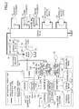
- FIG. 2 is a block diagram showing a configuration of a drive system of a hybrid excavator according to an embodiment of the present invention.
- the double line denotes a mechanical drive line
- the thick solid line denotes a high voltage hydraulic line
- the dotted line denotes a pilot line
- the thin solid line denotes an electric drive/control line.
- An engine 11 as a mechanical drive part and a motor generator 12 as an assist drive part are connected to two input axes of a gearbox 13, respectively.
- a main pump 14 as a hydraulic pump and a pilot pump 15 are connected to the output axis of the gearbox 13.
- a control valve 17 is connected to the main pump 14 via a high voltage hydraulic line 16.
- the control valve 17 is a control unit that controls a hydraulic system of the hybrid excavator.
- a hydraulic motor 1A (for the right side) and a hydraulic motor 1B (for the left side) are provided for driving the lower running body 1.
- the hydraulic motors 1A and 1B, the boom cylinder 7, the arm cylinder 8, and the bucket cylinder 9 are connected to the control valve 17 via the high voltage hydraulic line.
- An electrical energy storage system (electrical energy storage unit) 120 including a capacitor as an electrical energy storage device is connected to the motor generator 12 via an inverter 18A.
- a turning motor 21 as an electric work element is connected to the electrical energy storage system 120 via an inverter 20.
- a resolver 22, a mechanical brake 23, and a turning gearbox 24 are connected to the axis of rotation 21A of the turning motor 21.
- An operation device 26 is connected to the pilot pump 15 via the pilot line 25.
- the turning motor 21, the inverter 20, the resolver 22, the mechanical brake 23, and the turning gearbox 24 comprise a load drive system.
- the operation device 26 includes a lever 26A, a lever 26B, and a pedal 26C.
- the lever 26A, the lever 26B, and the pedal 26C are connected to each of the control valve 17 and a voltage sensor 29 via a hydraulic line 27 and a hydraulic line 28, respectively.
- the voltage sensor 29 is connected to a controller 30, and the controller 30 performs drive control of an electric system.
- a boom regeneration motor 300 (also referred to as "generator 300") for obtaining boom regeneration power is connected to the electrical energy storage system 120 via an inverter 18C.
- the generator 300 is driven by a hydraulic motor 310, which is driven by a hydraulic fluid discharged from the boom cylinder 7.
- the generator 300 converts the potential energy of the boom 4 into electrical energy by using the voltage of the hydraulic fluid discharged from the boom cylinder 7 when the boom 4 is lowered by gravity.
- the hydraulic motor 310 and the generator 300 are illustrated at separate locations for the sake of convenience of description. However, in practical applications, the axis of rotation of the generator 300 is mechanically connected to the axis of rotation of the hydraulic motor 310.
- the hydraulic motor 310 is arranged so that the hydraulic motor 310 is rotated by the hydraulic fluid that is discharged from the boom cylinder 7 when the boom 4 is lowered.
- the hydraulic motor 310 is configured to convert the energy generated when the boom 4 is lowered by gravity into a rotational force.
- the hydraulic motor 310 is arranged in a hydraulic piping 7A between the control valve 17 and the boom cylinder 7.
- the hydraulic motor 310 may be attached to a suitable location within the upper turning body 3.
- the electric power generated by the generator 300 is supplied to the electrical energy storage system 120 through the inverter 18C as regeneration power.
- the generator 300 and the inverter 18C comprise a load drive system.
- a boom angle sensor 7B for detecting the angle of the boom 4 is attached to the supporting shaft of the boom 4.
- the boom angle sensor 7B supplies the detected boom angle ⁇ B to the controller 30.
- FIG. 3 is a block diagram illustrating a configuration of the electrical energy storage system 120.
- the electrical energy storage system 120 includes a capacitor 19 as a first electrical energy storage part, an up-down voltage converter 100, and a DC bus 110.
- the DC bus 110 corresponds to a second electrical energy storage part that controls transfer of electric power between the capacitor 19 corresponding to the first electrical energy storage part, the motor generator 12, and the turning motor 21.
- a capacitor voltage detecting part 112 for detecting a capacitor voltage value and a capacitor current detecting part 113 for detecting a capacitor current value are arranged at the capacitor 19. The capacitor voltage value and the capacitor current value detected by the capacitor voltage detecting part 112 and the capacitor current detecting part 113 are supplied to the controller 30.
- the up-down voltage converter 100 controls switching between a voltage raising operation and a voltage lowering operation according to the operating states of the motor generator 12, the generator 300, and the turning motor 21 so that the DC bus voltage value falls within a certain range.
- the DC bus 110 corresponding to the second electrical energy storage part is arranged between the inverters 18A, 18C, and 20 and the up-down voltage converter 100, and is configured to transfer electric power between the capacitor 19, the motor generator 12, the generator 300, and the turning motor 21.
- the controller 30 corresponds to a control unit that acts as a main control part performing drive control of the hybrid excavator.
- the controller 30 comprises a processor unit that includes a CPU (central processing unit) and an internal memory.
- the functions of the controller 30 are implemented by the CPU executing a drive control program stored in the internal memory.
- the controller 30 converts the signal received from the voltage sensor 29 into a speed command, and performs drive control of the turning motor 21 using the speed command.
- the signal received from the voltage sensor 29 is equivalent to the signal indicating the operational amount when the operation device 26 is operated to turn the turning mechanism 2.
- the controller 30 controls operation of the motor generator 12 (switching of a motor-assisted operation and a power generating operation), and controls operation of the up-down voltage converter 100 as the voltage raising/lowering control unit to control charging/discharging of the capacitor 19.
- the controller 30 controls switching of the voltage raising operation and the voltage lowering operation of the up-down voltage converter 100 based on the charge state of the capacitor 19, the operating state of the motor generator 12 (motor-assisted operation or power generating operation) and the operating state (power operation or regeneration operation) of the turning motor 21, so that the charging/discharging of the capacitor 19 is controlled.
- the controller 30 controls a charge amount (amount of charge current or charge power) to the capacitor 19 as described in detail below.
- the switching control between the voltage raising operation and the voltage lowering operation of the up-down voltage converter 100 is carried out based on the DC bus voltage value detected by the DC bus voltage detecting part 111, the capacitor voltage value detected by the capacitor voltage detecting part 112, and the capacitor current value detected by the capacitor current detecting part 113.
- the power generated by the motor generator 12 corresponding to an assist motor is supplied to the DC bus 110 of the electrical energy storage system 120 via the inverter 18A, and supplied to the capacitor 19 via the up-down voltage converter 100.
- the regeneration power obtained by the regeneration operation of the turning motor 21 is supplied to the DC bus 110 of the electrical energy storage system 120 via the inverter 20, and supplied to the capacitor 19 via the up-down voltage converter 100.
- the power generated by the boom regeneration motor 300 is supplied to the DC bus 110 of the electrical energy storage system 120 via the inverter 18C, and supplied to the capacitor 19 via the up-down voltage converter 100.
- the rotational speed (the angular velocity ⁇ ) of the turning motor 21 is detected by the resolver 22.
- the angle (the boom angle ⁇ B) of the boom 4 is detected by the boom angle sensor 7B, such as a rotary encoder, arranged at the supporting shaft of the boom 4.
- the controller 30 computes an estimated turning regeneration power (energy) based on the angular velocity ⁇ of the turning motor 21, and computes an estimated boom regeneration power (energy) based on the boom angle ⁇ B. Based on the estimated turning regeneration power and the estimated boom regeneration power obtained through such computations, the controller 30 computes (determines) an estimated regeneration target value (electrical energy storage target value) for the SOC.
- the controller 30 controls the respective parts of the hybrid excavator so that the SOC of the capacitor 19 comes close to the computed estimated regeneration target value.
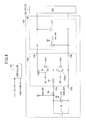
- FIG. 4 is a circuit diagram of the electrical energy storage system 120.
- the up-down voltage converter 100 includes a reactor 101, a voltage raising IGBT (insulated gate bipolar transistor) 102A, a voltage lowering IGBT 102B, a pair of power supply connection terminals 104 for connecting the capacitor 19, a pair of output terminals 106 for connecting the DC bus 110, and a smoothing capacitor 107 connected in parallel to the output terminals 106.
- the DC bus 110 is connected between the output terminals 106 of the up-down voltage converter 100 and the inverters 18A, 18C, and 20.
- One end of the reactor 101 is connected to the midpoint of the voltage raising IGBT 102A and the voltage lowering IGBT 102B, and the other end of the reactor 101 is connected to one of the power supply connection terminals 104.
- the reactor 101 is arranged to supply an induced electromotive force that is generated upon switching ON/OFF the voltage raising IGBT 102A to the DC bus 110.
- Each of the voltage raising IGBT 102A and the voltage lowering IGBT 102B is formed by a bipolar transistor in which a MOSFET (metal oxide semiconductor field effect transistor) is incorporated in the gate portion.
- Each of the voltage raising IGBT 102A and the voltage lowering IGBT 102B is a semiconductor element that is capable of switching large electric power at high speed.
- Each of the voltage raising IGBT 102A and the voltage lowering IGBT 102B is driven by the controller 30 supplying a PWM voltage to the gate terminal.
- a diode 102a and a diode 102b, which are rectifier elements, are connected in parallel to the voltage raising IGBT 102A and the voltage lowering IGBT 102B respectively.
- the capacitor 19 may be a chargeable and dischargeable capacitor that enables transfer of electric power between the capacitor 19 and the DC bus 110 via the up-down voltage converter 100. It is noted that although the capacitor 19 is illustrated as an example of the first electrical energy storage part in FIG. 4 , a chargeable and dischargeable secondary battery, such as a lithium ion battery, a lithium ion capacitor, or some other form of power supply that can deliver and receive electric power may be used instead of the capacitor 19.
- a chargeable and dischargeable secondary battery such as a lithium ion battery, a lithium ion capacitor, or some other form of power supply that can deliver and receive electric power may be used instead of the capacitor 19.
- the power supply connection terminals 104 and the output terminals 106 are terminals to which the capacitor 19 and the DC bus 110 are connected.
- the capacitor voltage detecting part 112 for detecting the capacitor voltage value is connected between the power supply connection terminals 104.
- the DC bus voltage detecting part 111 for detecting the DC bus voltage value is connected between the output terminals 106.
- the capacitor voltage detecting part 112 detects the voltage value of the capacitor 19 (capacitor voltage: vbat_det).
- the DC bus voltage detecting part 111 detects the voltage value of the DC bus 110 (DC bus voltage: vdc_det).
- the smoothing capacitor 107 is an electrical energy storage element that is inserted between the positive-electrode terminal and the negative-electrode terminal of the output terminals 106 and is configured to smooth the DC bus voltage.
- the voltage of the DC bus 110 is maintained at a predetermined voltage by the smoothing capacitor 107.
- the capacitor current detecting part 113 is a detecting part for detecting the value of the current that flows through the capacitor 19.
- the capacitor current detecting part 113 includes a resistor for current detection.
- the capacitor current detecting part 113 detects the current value of the current flowing through the capacitor 19 (capacitor current: ibat_det).
- the PWM voltage is supplied to the gate terminal of the voltage raising IGBT 102A, and the induced electromotive force generated at the reactor 101 in response to switching ON/OFF the voltage raising IGBT 102A is supplied to the DC bus 110 through the diode 102b connected in parallel to the voltage lowering IGBT 102B. Thereby, the voltage of the DC bus 110 is increased.
- the PWM voltage is supplied to the gate terminal of the voltage lowering IGBT 102B, and the regeneration power supplied via the voltage lowering IGBT 102B and the DC bus 110 is supplied from the DC bus 110 to the capacitor 19. Thereby, the capacitor 19 is charged by the power stored in the DC bus 110 and the voltage of the DC bus 110 is lowered.
- a drive part which generates the PWM signal for driving the voltage raising IGBT 102A and the voltage lowering IGBT 102B, is arranged between the controller 30 and each of the voltage raising IGBT 102A and the voltage lowering IGBT 102B.
- the illustration of the drive part is omitted in FIG. 4 .
- Such a drive part may be implemented by either an electronic circuit or a processor unit.
- charge rate SOC the SOC of the capacitor 19 representing a charge rate of the capacitor 19
- charge rate SOC the SOC of the capacitor 19 representing a charge rate of the capacitor 19
- the capacitor 19 is repeatedly charged and discharged so that the charge rate SOC of the capacitor 19 constantly changes. That is, when the capacitor 19 is discharged to drive an electric load, the charge rate SOC decreases, and when the capacitor 19 is charged with the electric power generated by the motor generator 12 or the regenerative power generated by the generator (boom regeneration motor) 300, the charge rate SOC increases.
- an upper limit value and a lower limit value for system control of the charge rate SOC of the capacitor 19 are determined (referred to as "system control upper limit value” and "system control lower limit value” hereinafter).
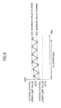
- FIG. 5 is a graph illustrating a change of the charge rate SOC of the capacitor 19 during operation of the excavator.
- the system control upper limit value for the charge rate SOC is set equal to 90%
- the system control lower limit value is set equal to 40%.
- the system control upper limit value and the system control lower limit value are not limited to these values but may be set to other suitable values according to the drive system of the excavator and the state of the capacitor 19, for example. It is assumed that a 100% charge rate SOC of the capacitor 19 corresponds to the charge rate of the capacitor 19 when the capacitor 19 is at its rated voltage.
- the charge rate SOC of the capacitor 19 starts increasing. At some point, the capacitor 19 may have to discharge power to drive the electric load once again. At such a point, the charge rate SOC transitions from an increase to a decrease. It is noted that the point at which the charge rate SOC transitions from an increase to a decrease is referred to as "maximum value”.
- the change of the charge rate SOC of the capacitor 19 may oftentimes be represented by a repetition of similar waveforms such as those illustrated in FIG. 5 .
- certain limits are imposed on the charge current supplied to the capacitor 19. That is, an upper limit value for the charge current is set up, and the charge current supplied to the capacitor 19 is controlled to be less than or equal to the upper limit value.
- the value of the charge current for the capacitor 19 is proportional to the rising speed of the charge rate SOC.
- the charge current has to be controlled to be within a certain limit and the upper limit value for the charge current is set up. That is, the charge current (or charge power) for the capacitor 19 is controlled to be less than or equal to a certain upper limit value.
- the charge current (amount of charge) used for the repeated charging operations is a sufficiently large current for maintaining the charge rate SOC at the desired level and the average value of the charge rate SOC (the intermediate value of the minimum value and the maximum value) gradually increases. Then, because charge rate SOC is controlled to not exceed the system control upper limit value, the maximum value of the charge rate SOC is retained at the system control upper limit value. Thus, in the example illustrated in FIG. 5 , the average value of the charge rate SOC is always maintained at a desirably high level.
- the charge current or the charge power is controlled so that the charge rate SOC may be maintained as high as possible to make efficient use of the capacitor 19.
- the charge rate SOC is controlled to be maintained at a desirably high level while it changes by controlling the amount of charge (amount of charge current or charge power) to the capacitor 19 based on a changing trend of the charge rate SOC of the capacitor 19. More specifically, charge power control or charge current control is switched between different stages according to a change (or changing trend) of the minimum value and the maximum value of the charge rate SOC so as to control and maintain the charge rate SOC at a desirably high level.
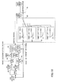
- FIG. 6 is a block diagram illustrating charge amount control according to a first embodiment of the present invention.
- the minimum value and the maximum value of the charge rate SOC of the capacitor 19 are computed based on input values of the present charge rate SOC of the capacitor 19 that are iteratively obtained with the progression of time.
- the computed minimum value is output to SOC decrease determination block 42, and the computed maximum value is output to SOC retention determination block 44.
- a determination is made as to whether the charge rate SOC is decreasing based on a change in the input minimum value. If it is determined that the charge rate SOC is decreasing, a power limit up flag is generated. Specifically, at the SOC decrease determination block 42, a present minimum value that is iteratively computed with the progression of time is compared to a previously computed minimum value and a determination is made as to whether the present minimum value has decreased (is smaller) with respect to the previous minimum value N consecutive times. It is noted that N denotes an arbitrary integer (minimum value consecutive decrease number). For example, assuming N 3, a determination is made as to whether the present minimum value has decreased with respect to the previous minimum value three consecutive times.
- the power limit up flag is a flag indicating that the charge rate SOC is likely to continue decreasing.
- the SOC retention determination block 44 a determination is made as to whether the charge rate has been retained based on a change in the maximum value. If it is determined that the charge rate SOC is retained, the power limit down flag is generated. Specifically, at the SOC retention determination block 44, a present maximum value that is iteratively computed with the progression of time is compared to a previously computed maximum value and a determination is made as to whether the present maximum value has been greater than or equal to the previous maximum value (retained) N consecutive times. It is noted that N denotes an arbitrary integer (maximum value consecutive increase number).
- the power limit down flag is a flag indicating that the charge rate SOC is likely to be retained.
- the present maximum value that is iteratively computed with the progression of time is compared to the system control upper limit value and a determination is made as to whether the present maximum value has been greater than or equal to the system control upper limit value (retained) N consecutive times.
- N denotes an arbitrary integer (maximum value consecutive increase number).
- the power limit down flag is also generated when it is determined that the maximum value has been retained at the system control upper limit value three consecutive times.
- a switch signal for switching a charge power limit stage is generated and supplied to a switch block 48.
- the charge power limit switch determination block 46 may supply a switch signal for switching the charge power limit stage to a stage that is one level higher to the switch block 48.
- the charge power limit switch determination block 46 may supply a switch signal for switching the charge power limit stage to the highest stage to the switch block 48.
- the charge power limit switch determination block 46 may supply a switch signal for switching the charge power limit stage to a stage that is one level lower to the switch block 48.
- the charge power limit stages define multi-tiered limits for the electrical energy to be supplied to the capacitor 19.
- stage A defines the charge power limit as less than or equal to -10 kW
- stage B as less than or equal to -20 kW
- stage C as less than or equal to -30 kW
- stage D as less than or equal to -40 kW.
- the switch block 48 is configured to select one of these stages based on the switch signal and output the corresponding charge power limit value (i.e., -10 kW, -20 kW, -30 kW, or -40 kW) to a limiter 50 corresponding to a limitation part.
- the limiter 50 receives a charge power command value 1 from the controller 30.
- the limiter 50 adds a corresponding limitation to the charge power command value 1 based on the charge power limit value supplied from the switch block 48 to generate a charge power command value 2 and outputs the generated charge power command value 2 to an upper-level system.
- the charge power command value 2 output from limiter 50 corresponds to a command value having a limitation added thereto based on the changing trend of the charge rate SOC.
- the charge power command value 2 corresponds to a value that is limited to be less than or equal to -10 kW, -20 kW, -30 kW, or -40 kW according to the changing trend of the charge rate SOC as described above.
- the charge power command value 2 corresponds to a command value for the charge power to be actually supplied to the capacitor 19.
- the charge power limit switch determination block 46 outputs a reset determination signal to the SOC decrease determination block 42 and the SOC retention determination block 44 in addition to outputting the switch signal to the switch block 48.
- the SOC decrease determination block 42 and the SOC retention determination block 44 reinitiates the comparison of the minimum value and the maximum value N consecutive times.
- the comparison of the minimum value and the maximum value N consecutive times is performed for the purpose of determining whether the charge rate SOC has an increasing tendency or a decreasing tendency.
- the determination does not necessarily have to be based on whether the minimum value has decreased N consecutive times or the maximum value has been retained N consecutive times. That is, as long as the changing trend of the charge rate SOC within a certain time period can be determined, the determination does not have to be based on comparisons of the minimum value and the maximum value made N consecutive times and may instead be based on comparisons made every other time, for example. Alternatively, the determination may be made based on the moving average of the minimum value and the maximum value, for example.
- the detection value to be detected for determining the changing trend of the charge rate SOC is not limited to the minimum value and the maximum value of the charge rate SOC.
- the detection value may be detected after a predetermined time period elapses from the time the charge rate reaches the minimum value or the maximum value.
- the determination may be made based on whether a change rate is greater than or equal to a predetermined value, for example.
- the changing trend of the charge rate SOC may be determined based on whether the difference between the detection value of the present charge rate SOC and the detection value of the charge rate SOC after a predetermined time period is greater than or equal to a predetermined value, for example.
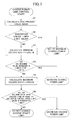
- FIG. 7 is a flowchart illustrating process steps of a charge amount control process.
- step S1 a present value SOC0 of the charge rate SOC of the capacitor 19 is computed.
- step S2 a determination is made as to whether the present value SOC0 of the charge rate SOC is below the system control lower limit value for the charge rate SOC (see FIG. 5 ).
- step S2 If the present value SOC0 of the charge rate SOC is below the system control lower limit value (step S2, YES), the charge power limit stage is switched to the highest stage (stage D). That is, because the current charge rate is too low, the capacitor 19 needs to be quickly charged. Thus, the charge power limit is set up to a maximum value so that a large charge power may be supplied to the capacitor 19.
- step S2 if the present value SOC0 of the charge rate SOC is greater than or equal to the system control lower limit value (step S2, NO), the process proceeds to step S3.
- step S3 the minimum value of the charge rate SOC is calculated N times.
- SOC-1 denotes the first calculated value and SOC-N denotes the Nth calculated value.
- step S4 a determination is made as to whether the minimum value of the charge rate SOC has decreased N consecutive times.
- the charge power limit stage is switched to a stage that is one level higher to increase the charge power limit value. For example, if the charge power limit stage at the time the minimum value of the charge rate SOC has decreased N consecutive times corresponds to stage B, the charge power limit stage is switched to stage C and the charge power limit value is increased from -20 kW of stage B to -30 kW of stage C. It is noted that the charge power limit value is expressed as a negative value in order to distinguish the charge power from the discharge power, which is expressed as a positive value. Thus, in the case where the capacitor 19 is charged at -20 kW maximum, by switching the charge power limit value, the capacitor 19 may be charged at -30 kW maximum so that the capacitor 19 may be quickly charged to counter the decreasing tendency of the charge rate SOC.
- step S5 the maximum value of the charge rate SOC is calculated N times.
- SOC+1 denotes the initial calculated value and SCO+N denotes the Nth calculated value.
- step S6 a determination is made as to whether the maximum value of the charge rate SOC has been greater than or equal to the system control upper limit value for the charge rate SOC (see FIG. 5 ) N consecutive times, or whether the maximum value of the charge rate has increased N consecutive times.
- the charge power limit stage is switched to a stage that is one level lower to decrease the charge power limit value. For example, if the charge power limit stage at the time the maximum value of the charge rate SOC has increased N consecutive times corresponds to stage C, the charge power limit stage is switched to stage B and the charge power limit value is decreased from -30 kW of stage C to -20 kW of stage B. It is noted that the charge power limit value is expressed as a negative value in order to distinguish the charge power from the discharge power, which is expressed as a positive value.
- charge power to be supplied to the capacitor 19 may be limited to -20 kW maximum so that the amount of charge to the capacitor 19 may be reduced and the charge rate SOC may be controlled to decrease.
- step S6 NO if it is determined that the maximum value of the charge rate SOC has not been greater than or equal to the system control upper limit value for the charge rate SOC N consecutive times or that the maximum value of the charge rate SOC has not increased N consecutive times (step S6, NO), the charge amount limit stage is maintained as is and the charge amount limit value is not changed.
- the maximum value of the charge rate SOC has not been greater than or equal to the system control upper limit value for the charge rate SOC N consecutive times; namely, if the case where the maximum value of the charge rate SOC becomes greater than or equal to the system control upper limit value does not occur N consecutive times, or the maximum value of the charge rate SOC has not increased N consecutive times, it is determined that the charge rate SOC of the capacitor 19 has not been increased to an exceedingly high level so that the current charge power limit does not have to be decreased. Thus, the charge power limit is not decreased in this case.
- FIG. 8 illustrates a change in the charge rate SOC and a corresponding charge power limit in an exemplary charge power limit control according to the present embodiment.
- the charge rate SOC of the capacitor 19 gradually decreases from the system control upper limit value (e.g., 90%), and in turn, the maximum value and the minimum value of the charge rate SOC gradually decreases over time.
- the charge power limit value is increased from -10 kW to -20 kW (where the negative symbol denotes a charge).
- the charge rate SOC continues to decrease, and this time, the minimum value falls below the system control lower limit value.
- the charge power limit stage is switched to the highest stage; namely, from stage B to stage D. In this way, the charge power limit value is increased from -20 kW to -40 kW so that the capacitor 19 may be charged more quickly.
- the charge power limit stage is switched to a stage that is one level lower.
- FIG. 9 illustrates a change in the charge rate SOC and a corresponding charge power limit of another exemplary charge power limit control according to the present embodiment.
- the charge rate SOC of the capacitor 19 gradually decreases from the system control upper limit value (e.g., 90%), and in turn, the maximum value and the minimum value of the charge rate SOC gradually decreases over time.
- the charge power limit stage is switched to a stage that is one level higher; namely, from stage A to stage B. In this way, the charge power limit value is increased from -10 kW to -20 kW (where the negative symbol demotes a charge).
- the charge power limit stage is switched to a stage that is one level lower; namely, from stage B to stage A. In this way, the charge power limit value is decreased from -20 kW to -10 kW so that the charge power is controlled to decrease.
- the charge power limit control according to the present embodiment is implemented based on the SOC of the capacitor 19 as the charge rate
- the voltage value of the electrical energy storage unit may be used as the charge rate instead of the SOC, for example.
- the charge rate SOC may be controlled to be within the system control upper limit value.
- the charge power limit may be decreased in a case where the charge rate SOC is consecutively retained at the system control upper limit value.
- FIG. 10 is a block diagram illustrating charge amount control according to the second embodiment. It is noted that in FIG. 10 , functional blocks that correspond to those illustrated in FIG. 6 are given the same reference numerals and their descriptions are omitted.
- the switch block 48 of FIG. 6 is replaced by a map switch block 60, and the charge power command value 1 is output from the map switch block 60.
- the charge power command value 1 is supplied to an upper-level process.
- a charge power command value determined at the upper level process exceeds the charge power command value 1, the command value is limited by a limiter 70 and the resulting command value is output from the limiter 70 as charge power command value 2.
- the map switch block 60 includes a plurality of maps 62-1 through 62-4 for generating the charge power command value 1.
- Map 62-1 represents a relationship between the charge rate SOC and the charge power limit value for stage A.
- Map 62-1 corresponds to a map for controlling the charge power so that the charge current flowing through the capacitor 19 does not exceed a predetermined current value (current value for stage A) regardless of the value of the charge rate SOC.
- maps 62-2, 62-3, and 62-4 represent the relationship between the charge rate SOC and the charge power limit value for stage B, stage C, and stage D, respectively.
- charge power command values 1 limited by the charge power limit values set up for stage B, stage C, and stage D are output by the maps 62-2, 62-3, and 62-4, respectively.
- the maps 62-2, 62-3, and 62-4 correspond to maps for controlling the charge power so that the charge current flowing through the capacitor 19 does not exceed a predetermined current value (current values of stage B, stage C, and stage D) regardless of the value of the charge rate SOC.
- a predetermined current value current values of stage B, stage C, and stage D
- the capacitor 19 may be charged at a current value that does not exceed the predetermined value (current values for stage B, stage C, and stage D) regardless of the value of the charge rate SOC.
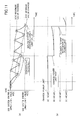
- FIG. 11 illustrates a change in the charge rate SOC and a corresponding charge power limit in an exemplary charge power limit control according to the present embodiment.
- the charge rate SOC of the capacitor 19 gradually decreases from the system control upper limit value (e.g., 90%), and in turn, the maximum value and the minimum value of the charge rate SOC gradually decreases.
- the charge power limit value is increased from the limit value of map 62-1 (stage A: -10 kW maximum) to the limit value of map 62-2 (stage B: -20 kW maximum) (where the negative symbol denotes a charge).
- the charge rate SOC continues to decrease, and this time, the minimum value falls below the system control lower limit value. Accordingly, at the time point where the minimum value falls below the system control lower limit value, the charge power limit stage is switched to the highest stage; namely, from stage B to stage D.
- the charge power limit value is increased from the limit value of map 62-2 (stage B: -20 kW maximum) to the limit value of map 62-4 (stage D: -40 kW maximum (maximum charge power)) so that the capacitor 19 may be charged more quickly.
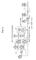
- FIG. 12 is a block diagram illustrating the charge amount control according to the third embodiment. It is noted that in FIG. 12 , functional blocks that correspond to those illustrated in FIG. 6 are given the same reference numerals and their descriptions are omitted.
- the switch block 48 illustrated in FIG. 6 is replaced by a gain computation block 80 and a proportional control block 82, and the charge power command value 1 is output from the proportional control block 82. Also, a difference between the present value of the charge rate SOC and a SOC target value is input to the proportional control block 82.
- the charge power command value 1 output from the proportional control block 82 is supplied to an upper-level process. In a case where a charge power command value determined at the upper-level process is greater than the charge power command value 1, the command value is limited by a limiter 70 and the resulting command value is output from the limiter 70 as charge power command value 2.
- the gain computation block 80 calculates a proportional gain for each stage based on the switch signal from the charge power limit switch determination block 46.
- the proportional control block 82 calculates the charge power command value 1 based on the difference between the charge rate SOC present value and the SOC target value and the proportional gain obtained by the gain computation block 80.
- the charge power command value 1 is supplied to an upper-level process. In a case where a charge power command value determined at the upper-level process is greater than the charge power command value 1, the charge power command value is limited by a limiter 70 and the resulting command value is output from the limiter 70 as charge power command value 2.
- FIG. 13 illustrates a change in the charge rate SOC and a corresponding charge power limit in an exemplary charge power limit control according to the present embodiment.
- the charge rate SOC of the capacitor 19 gradually decreases from the system control upper limit value (e.g., 90%), and in turn, the maximum value and the minimum value of the charge rate SOC gradually decreases.
- the charge power limit value is increased from the limit value for stage A (-10 kW + proportional gain) to the limit value of stage B (-20 kW + proportional gain) (where the negative symbol denotes a charge).
- the charge rate SOC continues to decrease, and this time, the minimum value falls below the system control lower limit value.
- the charge power limit stage is switched to the highest stage; namely, from stage B to stage D. In this way, the charge power limit value is increased from the limit value for stage B (-20 kW + proportional gain) to the limit value for stage D (maximum charge power: -40 kW + proportional gain) so that the capacitor 19 may be charged more quickly.
- the above described embodiments relate to applications of the present invention to the so-called parallel hybrid excavator that has the engine 11 and the motor generator 12 connected to the main pump 14 (hydraulic pump) to drive the main pump 14.
- the present invention may be applied to the so-called series hybrid excavator as illustrated in FIG. 14 , for example, in which the motor generator 12 is driven by the engine 11, electric power generated by the motor generator 12 is stored in the electrical energy storage system 120, and the main pump 14 is driven solely by the electric power stored in the electrical energy storage system 120.
- the motor generator 12 may only have a generator function for generating electric power upon being driven by the engine 11.
- the present disclosure may be applied to a hybrid excavator as illustrated in FIG. 15 , for example, in which all the drive parts are hydraulically actuated.
- electric power generated by the motor generator 12 by using excess power of the engine 11 and electric power generated by the boom regeneration motor 300 are stored in the electrical energy storage system 120.
- the electric power stored in the electrical energy storage system 120 is used to assist the output of the engine 11.
- FIG. 16 is a block diagram illustrating an exemplary configuration of a drive system of such an electric excavator.
- the motor generator 12 that functions as the generator is connected to the main pump 14 corresponding to a hydraulic pump, and the main pump 14 is driven solely by the motor generator 12.
- the electrical energy storage system 120 is connected to an external power source 400 via a converter 410, and the electrical energy storage part (capacitor 19) of the electrical energy storage system 120 is charged with an electric power supply from the external power source 400.
- the present invention is applicable to an excavator having an electrical energy storage unit for supplying electric power to an electric work element.
Abstract
Description
- The present disclosure relates to an excavator that includes an electrical energy storage unit for supplying electric power to an electric work element.
- An excavator with an electric work element that is driven by an electric motor or an electric actuator generally includes an electrical energy storage unit for supplying electric power to the electric work element. A hybrid excavator with a motor generator for assisting an engine (assist motor) generally includes an electrical energy storage unit including an electrical energy storage device or a battery for storing the electric power obtained by driving the motor generator. The assist motor is driven by the electric power from the electric energy storage unit to assist the engine. Also, the assist motor is driven by the power of the engine to generate power. The generated electric power is stored in the electrical energy storage device or battery of the electrical energy storage unit.
- To supply electric power as requested, the electrical energy storage device or battery of the electrical energy storage unit is controlled so that its charge rate (e.g., SOC) may always be at least a certain value. Thus, when the charge rate (SOC) is dramatically decreased, a large charge current may be supplied to the electrical storage unit in an attempt to rapidly increase the charge rate (SOC). Because the electrical energy storage device or battery has internal resistance, heat generation may occur when a charge current is supplied thereby resulting in internal resistance power loss. Because the internal resistance power loss is proportional to the square of the current, the internal resistance power loss abruptly increases when the charge current is increased. Thus, to reduce the internal resistance and make efficient use of the electrical energy storage device or battery, the charge current is preferably arranged to be as small as possible.
- In this respect, for example, Japanese Unexamined Patent Publication No.
2009-114653 -
- Patent Document 1: Japanese Unexamined Patent Publication No.
2009-114653 - In a case where one upper limit value is set up with respect to a charge current to be supplied to an electrical energy storage device or a battery and this upper limit value is set equal to a relatively high value, when the charge current is controlled to be only slightly below the upper limit value, a relatively large internal resistance power loss may occur and power supply may be inefficient. On the other hand, in a case where the upper limit value is set equal to a relatively low value, only a small charge current may be supplied so that the charge speed may decrease and the charge rate (SOC) may be not retained at a desirably high level.
- Accordingly, the charge current or the charge power for the electrical energy storage unit is preferably controlled taking into account the charge rate (SOC) of the electrical energy storage device to make efficient use of the electrical energy storage part (electrical energy storage device or battery) of the electrical energy storage unit.
- According to an embodiment of the present invention, an excavator is provided that includes an electric load, an electrical energy storage unit including an electrical energy storage part that supplies electric power to the electric load, and a control unit that controls an amount of charge to the electrical energy storage part so that a charge rate of the electrical energy storage part is between a system control upper limit value and a system control lower limit value. The control unit controls the amount of charge to the electrical energy storage part based on a changing trend of a detection value of the charge rate.
- According to an aspect of the present invention, by controlling an amount of charge to an electrical energy storage unit based on a changing trend of the charge rate (e.g., SOC) of the electrical energy storage unit, charge power loss may be reduced and efficient power storage may be enabled, for example.
-
-
FIG. 1 is a side view of a hybrid excavator; -
FIG. 2 is a block diagram illustrating a configuration of a drive system of a hybrid excavator according to an embodiment of the present invention; -
FIG. 3 is a block diagram illustrating a configuration of an electrical energy storage system; -
FIG. 4 is a circuit diagram of the electrical energy storage system; -
FIG. 5 is a graph illustrating a change in the charge rate of a capacitor during operation of the excavator; -
FIG. 6 is a block diagram illustrating charge amount control according to a first embodiment of the present invention; -
FIG. 7 is a flowchart illustrating process steps of a charge amount control process; -
FIG. 8 is a graph illustrating a change in the charge rate and a corresponding charge power limit in an exemplary charge power limit control according to the first embodiment; -
FIG. 9 is a graph illustrating a change in the charge rate and a corresponding charge power limit in another exemplary charge power limit control according to the first embodiment; -
FIG. 10 is a block diagram illustrating charge amount control according to a second embodiment of the present invention; -
FIG. 11 is a graph illustrating a change in the charge rate and a corresponding charge power limit in an exemplary charge power control according to the second embodiment; -
FIG. 12 is a block diagram illustrating charge amount control according to a third embodiment of the present invention; -
FIG. 13 is a graph illustrating a change in the charge rate and a corresponding charge power limit in an exemplary charge power limit control according to the third embodiment; -
FIG. 14 is a block diagram illustrating a configuration of a drive system of a series hybrid excavator; -
FIG. 15 is a block diagram illustrating a configuration of a drive system of a hybrid excavator in which all the drive parts are hydraulically actuated; and -
FIG. 16 is a block diagram illustrating a configuration of an electric excavator. -
FIG. 1 is a side view of a hybrid excavator to which an embodiment of the present invention is implemented. - A lower running
body 1 of the hybrid excavator carries an upper turningbody 3 through aturning mechanism 2. A boom 4 is attached to the upper turningbody 3. Anarm 5 is attached at the end of the boom 4. Abucket 6 is attached at the end of thearm 5. The boom 4, thearm 5, and thebucket 6 are hydraulically driven by aboom cylinder 7, anarm cylinder 8, and abucket cylinder 9, respectively. Acabin 10 is arranged in the upper turningbody 3, and a power source, such as an engine, is mounted to the upper turningbody 3. - It is noted that the excavator implementing an embodiment of the present invention is not limited to a hybrid excavator. That is, the present invention may be implemented in any type of excavator that includes an electrical energy storage unit including an electric excavator that receives charge power from an external power source, for example.
-
FIG. 2 is a block diagram showing a configuration of a drive system of a hybrid excavator according to an embodiment of the present invention. InFIG. 2 , the double line denotes a mechanical drive line, the thick solid line denotes a high voltage hydraulic line, the dotted line denotes a pilot line, and the thin solid line denotes an electric drive/control line. - An
engine 11 as a mechanical drive part and amotor generator 12 as an assist drive part are connected to two input axes of agearbox 13, respectively. Amain pump 14 as a hydraulic pump and apilot pump 15 are connected to the output axis of thegearbox 13. Acontrol valve 17 is connected to themain pump 14 via a high voltagehydraulic line 16. - The
control valve 17 is a control unit that controls a hydraulic system of the hybrid excavator. Ahydraulic motor 1A (for the right side) and ahydraulic motor 1B (for the left side) are provided for driving the lower runningbody 1. Thehydraulic motors boom cylinder 7, thearm cylinder 8, and thebucket cylinder 9 are connected to thecontrol valve 17 via the high voltage hydraulic line. - An electrical energy storage system (electrical energy storage unit) 120 including a capacitor as an electrical energy storage device is connected to the
motor generator 12 via aninverter 18A. A turningmotor 21 as an electric work element is connected to the electricalenergy storage system 120 via aninverter 20. Aresolver 22, amechanical brake 23, and aturning gearbox 24 are connected to the axis ofrotation 21A of the turningmotor 21. Anoperation device 26 is connected to thepilot pump 15 via thepilot line 25. The turningmotor 21, theinverter 20, theresolver 22, themechanical brake 23, and the turninggearbox 24 comprise a load drive system. - The
operation device 26 includes alever 26A, a lever 26B, and apedal 26C. Thelever 26A, the lever 26B, and thepedal 26C are connected to each of thecontrol valve 17 and avoltage sensor 29 via ahydraulic line 27 and ahydraulic line 28, respectively. Thevoltage sensor 29 is connected to acontroller 30, and thecontroller 30 performs drive control of an electric system. - In the present embodiment, a boom regeneration motor 300 (also referred to as "
generator 300") for obtaining boom regeneration power is connected to the electricalenergy storage system 120 via aninverter 18C. Thegenerator 300 is driven by ahydraulic motor 310, which is driven by a hydraulic fluid discharged from theboom cylinder 7. Thegenerator 300 converts the potential energy of the boom 4 into electrical energy by using the voltage of the hydraulic fluid discharged from theboom cylinder 7 when the boom 4 is lowered by gravity. It is noted that inFIG. 2 , thehydraulic motor 310 and thegenerator 300 are illustrated at separate locations for the sake of convenience of description. However, in practical applications, the axis of rotation of thegenerator 300 is mechanically connected to the axis of rotation of thehydraulic motor 310. - That is, the
hydraulic motor 310 is arranged so that thehydraulic motor 310 is rotated by the hydraulic fluid that is discharged from theboom cylinder 7 when the boom 4 is lowered. Thehydraulic motor 310 is configured to convert the energy generated when the boom 4 is lowered by gravity into a rotational force. Thehydraulic motor 310 is arranged in ahydraulic piping 7A between thecontrol valve 17 and theboom cylinder 7. Thehydraulic motor 310 may be attached to a suitable location within theupper turning body 3. - The electric power generated by the
generator 300 is supplied to the electricalenergy storage system 120 through theinverter 18C as regeneration power. Thegenerator 300 and theinverter 18C comprise a load drive system. - In the present embodiment, a
boom angle sensor 7B for detecting the angle of the boom 4 is attached to the supporting shaft of the boom 4. Theboom angle sensor 7B supplies the detected boom angle θB to thecontroller 30. -
FIG. 3 is a block diagram illustrating a configuration of the electricalenergy storage system 120. The electricalenergy storage system 120 includes acapacitor 19 as a first electrical energy storage part, an up-downvoltage converter 100, and aDC bus 110. TheDC bus 110 corresponds to a second electrical energy storage part that controls transfer of electric power between thecapacitor 19 corresponding to the first electrical energy storage part, themotor generator 12, and the turningmotor 21. A capacitorvoltage detecting part 112 for detecting a capacitor voltage value and a capacitorcurrent detecting part 113 for detecting a capacitor current value are arranged at thecapacitor 19. The capacitor voltage value and the capacitor current value detected by the capacitorvoltage detecting part 112 and the capacitorcurrent detecting part 113 are supplied to thecontroller 30. - The up-down
voltage converter 100 controls switching between a voltage raising operation and a voltage lowering operation according to the operating states of themotor generator 12, thegenerator 300, and the turningmotor 21 so that the DC bus voltage value falls within a certain range. TheDC bus 110 corresponding to the second electrical energy storage part is arranged between theinverters voltage converter 100, and is configured to transfer electric power between thecapacitor 19, themotor generator 12, thegenerator 300, and the turningmotor 21. - Referring back to
FIG. 2 , thecontroller 30 corresponds to a control unit that acts as a main control part performing drive control of the hybrid excavator. Thecontroller 30 comprises a processor unit that includes a CPU (central processing unit) and an internal memory. The functions of thecontroller 30 are implemented by the CPU executing a drive control program stored in the internal memory. - The
controller 30 converts the signal received from thevoltage sensor 29 into a speed command, and performs drive control of the turningmotor 21 using the speed command. The signal received from thevoltage sensor 29 is equivalent to the signal indicating the operational amount when theoperation device 26 is operated to turn theturning mechanism 2. - The
controller 30 controls operation of the motor generator 12 (switching of a motor-assisted operation and a power generating operation), and controls operation of the up-downvoltage converter 100 as the voltage raising/lowering control unit to control charging/discharging of thecapacitor 19. Thecontroller 30 controls switching of the voltage raising operation and the voltage lowering operation of the up-downvoltage converter 100 based on the charge state of thecapacitor 19, the operating state of the motor generator 12 (motor-assisted operation or power generating operation) and the operating state (power operation or regeneration operation) of the turningmotor 21, so that the charging/discharging of thecapacitor 19 is controlled. Also, thecontroller 30 controls a charge amount (amount of charge current or charge power) to thecapacitor 19 as described in detail below. - The switching control between the voltage raising operation and the voltage lowering operation of the up-down
voltage converter 100 is carried out based on the DC bus voltage value detected by the DC busvoltage detecting part 111, the capacitor voltage value detected by the capacitorvoltage detecting part 112, and the capacitor current value detected by the capacitorcurrent detecting part 113. - In the above-described configuration, the power generated by the
motor generator 12 corresponding to an assist motor is supplied to theDC bus 110 of the electricalenergy storage system 120 via theinverter 18A, and supplied to thecapacitor 19 via the up-downvoltage converter 100. The regeneration power obtained by the regeneration operation of the turningmotor 21 is supplied to theDC bus 110 of the electricalenergy storage system 120 via theinverter 20, and supplied to thecapacitor 19 via the up-downvoltage converter 100. The power generated by theboom regeneration motor 300 is supplied to theDC bus 110 of the electricalenergy storage system 120 via theinverter 18C, and supplied to thecapacitor 19 via the up-downvoltage converter 100. - The rotational speed (the angular velocity ω) of the turning
motor 21 is detected by theresolver 22. The angle (the boom angle θB) of the boom 4 is detected by theboom angle sensor 7B, such as a rotary encoder, arranged at the supporting shaft of the boom 4. Thecontroller 30 computes an estimated turning regeneration power (energy) based on the angular velocity ω of the turningmotor 21, and computes an estimated boom regeneration power (energy) based on the boom angle θB. Based on the estimated turning regeneration power and the estimated boom regeneration power obtained through such computations, thecontroller 30 computes (determines) an estimated regeneration target value (electrical energy storage target value) for the SOC. Thecontroller 30 controls the respective parts of the hybrid excavator so that the SOC of thecapacitor 19 comes close to the computed estimated regeneration target value. -
FIG. 4 is a circuit diagram of the electricalenergy storage system 120. The up-downvoltage converter 100 includes areactor 101, a voltage raising IGBT (insulated gate bipolar transistor) 102A, avoltage lowering IGBT 102B, a pair of powersupply connection terminals 104 for connecting thecapacitor 19, a pair ofoutput terminals 106 for connecting theDC bus 110, and a smoothingcapacitor 107 connected in parallel to theoutput terminals 106. TheDC bus 110 is connected between theoutput terminals 106 of the up-downvoltage converter 100 and theinverters - One end of the
reactor 101 is connected to the midpoint of thevoltage raising IGBT 102A and thevoltage lowering IGBT 102B, and the other end of thereactor 101 is connected to one of the powersupply connection terminals 104. Thereactor 101 is arranged to supply an induced electromotive force that is generated upon switching ON/OFF thevoltage raising IGBT 102A to theDC bus 110. - Each of the
voltage raising IGBT 102A and thevoltage lowering IGBT 102B is formed by a bipolar transistor in which a MOSFET (metal oxide semiconductor field effect transistor) is incorporated in the gate portion. Each of thevoltage raising IGBT 102A and thevoltage lowering IGBT 102B is a semiconductor element that is capable of switching large electric power at high speed. Each of thevoltage raising IGBT 102A and thevoltage lowering IGBT 102B is driven by thecontroller 30 supplying a PWM voltage to the gate terminal. Adiode 102a and adiode 102b, which are rectifier elements, are connected in parallel to thevoltage raising IGBT 102A and thevoltage lowering IGBT 102B respectively. - The
capacitor 19 may be a chargeable and dischargeable capacitor that enables transfer of electric power between thecapacitor 19 and theDC bus 110 via the up-downvoltage converter 100. It is noted that although thecapacitor 19 is illustrated as an example of the first electrical energy storage part inFIG. 4 , a chargeable and dischargeable secondary battery, such as a lithium ion battery, a lithium ion capacitor, or some other form of power supply that can deliver and receive electric power may be used instead of thecapacitor 19. - The power
supply connection terminals 104 and theoutput terminals 106 are terminals to which thecapacitor 19 and theDC bus 110 are connected. The capacitorvoltage detecting part 112 for detecting the capacitor voltage value is connected between the powersupply connection terminals 104. The DC busvoltage detecting part 111 for detecting the DC bus voltage value is connected between theoutput terminals 106. - The capacitor
voltage detecting part 112 detects the voltage value of the capacitor 19 (capacitor voltage: vbat_det). The DC busvoltage detecting part 111 detects the voltage value of the DC bus 110 (DC bus voltage: vdc_det). The smoothingcapacitor 107 is an electrical energy storage element that is inserted between the positive-electrode terminal and the negative-electrode terminal of theoutput terminals 106 and is configured to smooth the DC bus voltage. The voltage of theDC bus 110 is maintained at a predetermined voltage by the smoothingcapacitor 107. The capacitorcurrent detecting part 113 is a detecting part for detecting the value of the current that flows through thecapacitor 19. The capacitorcurrent detecting part 113 includes a resistor for current detection. The capacitorcurrent detecting part 113 detects the current value of the current flowing through the capacitor 19 (capacitor current: ibat_det). - When raising the voltage of the
DC bus 110 by the up-downvoltage converter 100, the PWM voltage is supplied to the gate terminal of thevoltage raising IGBT 102A, and the induced electromotive force generated at thereactor 101 in response to switching ON/OFF thevoltage raising IGBT 102A is supplied to theDC bus 110 through thediode 102b connected in parallel to thevoltage lowering IGBT 102B. Thereby, the voltage of theDC bus 110 is increased. - When lowering the voltage of the
DC bus 110 by the up-downvoltage converter 100, the PWM voltage is supplied to the gate terminal of thevoltage lowering IGBT 102B, and the regeneration power supplied via thevoltage lowering IGBT 102B and theDC bus 110 is supplied from theDC bus 110 to thecapacitor 19. Thereby, thecapacitor 19 is charged by the power stored in theDC bus 110 and the voltage of theDC bus 110 is lowered. - In practical applications, a drive part, which generates the PWM signal for driving the
voltage raising IGBT 102A and thevoltage lowering IGBT 102B, is arranged between thecontroller 30 and each of thevoltage raising IGBT 102A and thevoltage lowering IGBT 102B. However, the illustration of the drive part is omitted inFIG. 4 . Such a drive part may be implemented by either an electronic circuit or a processor unit. - In the hybrid excavator described above, the SOC of the
capacitor 19 representing a charge rate of the capacitor 19 (referred to as "charge rate SOC" hereinafter) is always maintained at a high level so that the voltage of thecapacitor 19 may be maintained at a high level. By charging thecapacitor 19 while its voltage is at a high level, the charge current supplied to the capacitor may be decreased. Thus, for purposes of reducing internal resistance power loss, the charge rate SOC of thecapacitor 19 is preferably maintained at a high level at all times. - However, during operation of the excavator, the
capacitor 19 is repeatedly charged and discharged so that the charge rate SOC of thecapacitor 19 constantly changes. That is, when thecapacitor 19 is discharged to drive an electric load, the charge rate SOC decreases, and when thecapacitor 19 is charged with the electric power generated by themotor generator 12 or the regenerative power generated by the generator (boom regeneration motor) 300, the charge rate SOC increases. Thus, in order to maintain the charge rate SOC of thecapacitor 19 at a high level, an upper limit value and a lower limit value for system control of the charge rate SOC of thecapacitor 19 are determined (referred to as "system control upper limit value" and "system control lower limit value" hereinafter). -
FIG. 5 is a graph illustrating a change of the charge rate SOC of thecapacitor 19 during operation of the excavator. In the example illustrated inFIG. 5 , the system control upper limit value for the charge rate SOC is set equal to 90%, and the system control lower limit value is set equal to 40%. However, the system control upper limit value and the system control lower limit value are not limited to these values but may be set to other suitable values according to the drive system of the excavator and the state of thecapacitor 19, for example. It is assumed that a 100% charge rate SOC of thecapacitor 19 corresponds to the charge rate of thecapacitor 19 when thecapacitor 19 is at its rated voltage. - When operation of the excavator is started and the
engine 11 is driven, power generation by themotor generator 12 is enabled. During operation of the excavator, normally, when an electric load is driven by the electric power of thecapacitor 19 so that the charge rate SOC of thecapacitor 19 decreases, thecapacitor 19 is immediately charged so that the charge rate SOC of thecapacitor 19 increases. That is, when the excavator starts operating, thecapacitor 19 discharges power to drive the electric load of the excavator so that its charge rate SOC gradually decreases. When the electric load ceases to be driven, thecapacitor 19 is charged so that its charge rate SOC starts increasing. It is noted that the point at which the change in the charge rate SOC transitions from a decrease to an increase is referred to as "minimum value". When charging of thecapacitor 19 is started, the charge rate SOC of thecapacitor 19 starts increasing. At some point, thecapacitor 19 may have to discharge power to drive the electric load once again. At such a point, the charge rate SOC transitions from an increase to a decrease. It is noted that the point at which the charge rate SOC transitions from an increase to a decrease is referred to as "maximum value". - Normally, operation of the excavator involves the performance of repetitive movements such as drilling. Thus, the change of the charge rate SOC of the
capacitor 19 may oftentimes be represented by a repetition of similar waveforms such as those illustrated inFIG. 5 . In the example illustrated inFIG. 5 , certain limits are imposed on the charge current supplied to thecapacitor 19. That is, an upper limit value for the charge current is set up, and the charge current supplied to thecapacitor 19 is controlled to be less than or equal to the upper limit value. - The value of the charge current for the
capacitor 19 is proportional to the rising speed of the charge rate SOC. When the charge current is large, the rising speed of the charge rate SOC is accelerated and the charge rate SOC changes at a faster rate from the minimum value to the maximum value inFIG. 5 so that thecapacitor 19 can be quickly charged. However, when the charge current for thecapacitor 19 is too large, problems such as heat generation may occur due to the internal resistance of thecapacitor 19. Thus, the charge current has to be controlled to be within a certain limit and the upper limit value for the charge current is set up. That is, the charge current (or charge power) for thecapacitor 19 is controlled to be less than or equal to a certain upper limit value. - In the example illustrated in
FIG. 5 , the charge current (amount of charge) used for the repeated charging operations is a sufficiently large current for maintaining the charge rate SOC at the desired level and the average value of the charge rate SOC (the intermediate value of the minimum value and the maximum value) gradually increases. Then, because charge rate SOC is controlled to not exceed the system control upper limit value, the maximum value of the charge rate SOC is retained at the system control upper limit value. Thus, in the example illustrated inFIG. 5 , the average value of the charge rate SOC is always maintained at a desirably high level. - It is noted that the greater the charge current for the
capacitor 19, the faster the rise of the charge rate SOC of thecapacitor 19 and the easier it is to maintain the charge rate SOC at the desired high level. However, because the energy loss caused by the internal resistance of thecapacitor 19 while thecapacitor 19 is charged is proportional to the square of the charge current, when the rising speed of the charge rate SOC of thecapacitor 19 is accelerated to an exceedingly high level, the energy efficiency of thecapacitor 19 is degraded. - Accordingly, in the present embodiment, the charge current or the charge power is controlled so that the charge rate SOC may be maintained as high as possible to make efficient use of the
capacitor 19. Specifically, in the present embodiment, the charge rate SOC is controlled to be maintained at a desirably high level while it changes by controlling the amount of charge (amount of charge current or charge power) to thecapacitor 19 based on a changing trend of the charge rate SOC of thecapacitor 19. More specifically, charge power control or charge current control is switched between different stages according to a change (or changing trend) of the minimum value and the maximum value of the charge rate SOC so as to control and maintain the charge rate SOC at a desirably high level. -
FIG. 6 is a block diagram illustrating charge amount control according to a first embodiment of the present invention. In the charge amount control according to the present embodiment, atcomputation block 40, the minimum value and the maximum value of the charge rate SOC of thecapacitor 19 are computed based on input values of the present charge rate SOC of thecapacitor 19 that are iteratively obtained with the progression of time. The computed minimum value is output to SOC decreasedetermination block 42, and the computed maximum value is output to SOCretention determination block 44. - At the SOC
decrease determination block 42, a determination is made as to whether the charge rate SOC is decreasing based on a change in the input minimum value. If it is determined that the charge rate SOC is decreasing, a power limit up flag is generated. Specifically, at the SOCdecrease determination block 42, a present minimum value that is iteratively computed with the progression of time is compared to a previously computed minimum value and a determination is made as to whether the present minimum value has decreased (is smaller) with respect to the previous minimum value N consecutive times. It is noted that N denotes an arbitrary integer (minimum value consecutive decrease number). For example, assuming N=3, a determination is made as to whether the present minimum value has decreased with respect to the previous minimum value three consecutive times. The power limit up flag is a flag indicating that the charge rate SOC is likely to continue decreasing. - Also, at the SOC
decrease determination block 42, a determination is made as to whether the input minimum value is less than or equal to the system control lower limit value. If the minimum value is determined to be less than or equal to the lower limit value, a power limit maximum up flag is generated. The power limit maximum up flag indicates that the charge rate SOC has fallen to an exceedingly low level so that thecapacitor 19 needs to be quickly charged. - On the other hand, at the SOC
retention determination block 44, a determination is made as to whether the charge rate has been retained based on a change in the maximum value. If it is determined that the charge rate SOC is retained, the power limit down flag is generated. Specifically, at the SOCretention determination block 44, a present maximum value that is iteratively computed with the progression of time is compared to a previously computed maximum value and a determination is made as to whether the present maximum value has been greater than or equal to the previous maximum value (retained) N consecutive times. It is noted that N denotes an arbitrary integer (maximum value consecutive increase number). For example, assuming N=3, a determination is made as to whether the present maximum value has been greater than or equal to the previous maximum value (retained) three consecutive times. The power limit down flag is a flag indicating that the charge rate SOC is likely to be retained. Also, at the SOCretention determination block 44, the present maximum value that is iteratively computed with the progression of time is compared to the system control upper limit value and a determination is made as to whether the present maximum value has been greater than or equal to the system control upper limit value (retained) N consecutive times. It is noted that N denotes an arbitrary integer (maximum value consecutive increase number). For example, assuming N=3, a determination is made as to whether the present maximum value has been retained at the system control upper limit value three consecutive times. It is noted that the power limit down flag is also generated when it is determined that the maximum value has been retained at the system control upper limit value three consecutive times. - Next, at charge power limit
switch determination block 46, a switch signal for switching a charge power limit stage is generated and supplied to aswitch block 48. For example, when the power limit up flag is generated, the charge power limitswitch determination block 46 may supply a switch signal for switching the charge power limit stage to a stage that is one level higher to theswitch block 48. Also, when the power limit maximum up flag is generated, the charge power limitswitch determination block 46 may supply a switch signal for switching the charge power limit stage to the highest stage to theswitch block 48. On the other hand, when the power limit down flag is generated, the charge power limitswitch determination block 46 may supply a switch signal for switching the charge power limit stage to a stage that is one level lower to theswitch block 48. - The charge power limit stages define multi-tiered limits for the electrical energy to be supplied to the
capacitor 19. For example, stage A defines the charge power limit as less than or equal to -10 kW, stage B as less than or equal to -20 kW, stage C as less than or equal to -30 kW, and stage D as less than or equal to -40 kW. Theswitch block 48 is configured to select one of these stages based on the switch signal and output the corresponding charge power limit value (i.e., -10 kW, -20 kW, -30 kW, or -40 kW) to alimiter 50 corresponding to a limitation part. - The
limiter 50 receives a chargepower command value 1 from thecontroller 30. Thelimiter 50 adds a corresponding limitation to the chargepower command value 1 based on the charge power limit value supplied from theswitch block 48 to generate a chargepower command value 2 and outputs the generated chargepower command value 2 to an upper-level system. Thus, the chargepower command value 2 output fromlimiter 50 corresponds to a command value having a limitation added thereto based on the changing trend of the charge rate SOC. In the present embodiment, the chargepower command value 2 corresponds to a value that is limited to be less than or equal to -10 kW, -20 kW, -30 kW, or -40 kW according to the changing trend of the charge rate SOC as described above. The chargepower command value 2 corresponds to a command value for the charge power to be actually supplied to thecapacitor 19. - It is noted that the charge power limit
switch determination block 46 outputs a reset determination signal to the SOCdecrease determination block 42 and the SOCretention determination block 44 in addition to outputting the switch signal to theswitch block 48. Upon receiving the reset signal, the SOCdecrease determination block 42 and the SOCretention determination block 44, reinitiates the comparison of the minimum value and the maximum value N consecutive times. - It is noted that the comparison of the minimum value and the maximum value N consecutive times is performed for the purpose of determining whether the charge rate SOC has an increasing tendency or a decreasing tendency. Thus, the determination does not necessarily have to be based on whether the minimum value has decreased N consecutive times or the maximum value has been retained N consecutive times. That is, as long as the changing trend of the charge rate SOC within a certain time period can be determined, the determination does not have to be based on comparisons of the minimum value and the maximum value made N consecutive times and may instead be based on comparisons made every other time, for example. Alternatively, the determination may be made based on the moving average of the minimum value and the maximum value, for example.
- Also, the detection value to be detected for determining the changing trend of the charge rate SOC is not limited to the minimum value and the maximum value of the charge rate SOC. For example, the detection value may be detected after a predetermined time period elapses from the time the charge rate reaches the minimum value or the maximum value. Also, the determination may be made based on whether a change rate is greater than or equal to a predetermined value, for example. Specifically, the changing trend of the charge rate SOC may be determined based on whether the difference between the detection value of the present charge rate SOC and the detection value of the charge rate SOC after a predetermined time period is greater than or equal to a predetermined value, for example.
- It is noted that although limitations are imposed on the charge power to implement charge amount control in the present embodiment, limitations may alternatively be imposed on the charge current to implement charge amount control for controlling the amount of charge to the
capacitor 19, for example. -
FIG. 7 is a flowchart illustrating process steps of a charge amount control process. First, when the charge amount control process is started, in step S1, a present value SOC0 of the charge rate SOC of thecapacitor 19 is computed. Then, in step S2, a determination is made as to whether the present value SOC0 of the charge rate SOC is below the system control lower limit value for the charge rate SOC (seeFIG. 5 ). - If the present value SOC0 of the charge rate SOC is below the system control lower limit value (step S2, YES), the charge power limit stage is switched to the highest stage (stage D). That is, because the current charge rate is too low, the
capacitor 19 needs to be quickly charged. Thus, the charge power limit is set up to a maximum value so that a large charge power may be supplied to thecapacitor 19. - On the other hand, if the present value SOC0 of the charge rate SOC is greater than or equal to the system control lower limit value (step S2, NO), the process proceeds to step S3.
- It is noted that the above process steps are performed before the charge amount control illustrated in
FIG. 6 is implemented. - Next, in step S3, the minimum value of the charge rate SOC is calculated N times. SOC-1 denotes the first calculated value and SOC-N denotes the Nth calculated value. After the Nth calculated value SOC-N is calculated, in step S4, a determination is made as to whether the minimum value of the charge rate SOC has decreased N consecutive times.
- If the minimum value of the charge rate SOC has decreased N consecutive times (step S4, YES), the charge power limit stage is switched to a stage that is one level higher to increase the charge power limit value. For example, if the charge power limit stage at the time the minimum value of the charge rate SOC has decreased N consecutive times corresponds to stage B, the charge power limit stage is switched to stage C and the charge power limit value is increased from -20 kW of stage B to -30 kW of stage C. It is noted that the charge power limit value is expressed as a negative value in order to distinguish the charge power from the discharge power, which is expressed as a positive value. Thus, in the case where the
capacitor 19 is charged at -20 kW maximum, by switching the charge power limit value, thecapacitor 19 may be charged at -30 kW maximum so that thecapacitor 19 may be quickly charged to counter the decreasing tendency of the charge rate SOC. - On the other hand, if it is determined that the minimum value of the charge rate SOC has not decreased N consecutive times (step S4, NO), the process proceeds to step S5. In step S5, the maximum value of the charge rate SOC is calculated N times. SOC+1 denotes the initial calculated value and SCO+N denotes the Nth calculated value. After the Nth calculated value SOC+N is calculated, in step S6, a determination is made as to whether the maximum value of the charge rate SOC has been greater than or equal to the system control upper limit value for the charge rate SOC (see
FIG. 5 ) N consecutive times, or whether the maximum value of the charge rate has increased N consecutive times. - If the maximum value of the charge rate SOC has been greater than or equal to the system control upper limit value for the charge rate SOC N consecutive times or if the maximum value of the charge rate SOC has increased N consecutive times (step S6, YES), the charge power limit stage is switched to a stage that is one level lower to decrease the charge power limit value. For example, if the charge power limit stage at the time the maximum value of the charge rate SOC has increased N consecutive times corresponds to stage C, the charge power limit stage is switched to stage B and the charge power limit value is decreased from -30 kW of stage C to -20 kW of stage B. It is noted that the charge power limit value is expressed as a negative value in order to distinguish the charge power from the discharge power, which is expressed as a positive value. Thus, in the case where the
capacitor 19 is charged at -30 kW maximum, by switching the charge power limit value, charge power to be supplied to thecapacitor 19 may be limited to -20 kW maximum so that the amount of charge to thecapacitor 19 may be reduced and the charge rate SOC may be controlled to decrease. - On the other hand, if it is determined that the maximum value of the charge rate SOC has not been greater than or equal to the system control upper limit value for the charge rate SOC N consecutive times or that the maximum value of the charge rate SOC has not increased N consecutive times (step S6, NO), the charge amount limit stage is maintained as is and the charge amount limit value is not changed. If the maximum value of the charge rate SOC has not been greater than or equal to the system control upper limit value for the charge rate SOC N consecutive times; namely, if the case where the maximum value of the charge rate SOC becomes greater than or equal to the system control upper limit value does not occur N consecutive times, or the maximum value of the charge rate SOC has not increased N consecutive times, it is determined that the charge rate SOC of the
capacitor 19 has not been increased to an exceedingly high level so that the current charge power limit does not have to be decreased. Thus, the charge power limit is not decreased in this case. - Next, the above charge power control process is described in greater detail.
-
FIG. 8 illustrates a change in the charge rate SOC and a corresponding charge power limit in an exemplary charge power limit control according to the present embodiment. In the example illustrated inFIG. 8 , the charge rate SOC of thecapacitor 19 gradually decreases from the system control upper limit value (e.g., 90%), and in turn, the maximum value and the minimum value of the charge rate SOC gradually decreases over time. In the example illustrated inFIG. 8 (a) , the number of determinations N is set equal to three (N=3). Thus, when the minimum value of the charge rate SOC has decreased with respect to a previous minimum value N=3 consecutive times, the charge power limit stage is switched to a stage that is one level higher; namely, the charge power limit stage is switched from stage A to stage B. In this way, the charge power limit value is increased from -10 kW to -20 kW (where the negative symbol denotes a charge). However, when the load increases thereafter, output of the engine assist operation by themotor generator 12 and/or output to the turningmotor 21 increase as well. Thus, the charge rate SOC continues to decrease, and this time, the minimum value falls below the system control lower limit value. Accordingly, as illustrated inFIG. 8 (b) , at the time point where the minimum value has fallen below the system control lower limit value, the charge power limit stage is switched to the highest stage; namely, from stage B to stage D. In this way, the charge power limit value is increased from -20 kW to -40 kW so that thecapacitor 19 may be charged more quickly. - It is noted that although
FIG. 8 illustrates an exemplary case where the minimum value of the charge rate SOC decreases with respect to a previous minimum value N=3 consecutive times, in a case where the maximum value of the charge rate SOC increases with respect to a previous maximum value N=3 consecutive times, the charge power limit stage is switched to a stage that is one level lower. -
FIG. 9 illustrates a change in the charge rate SOC and a corresponding charge power limit of another exemplary charge power limit control according to the present embodiment. In the example illustrated inFIG. 9 , the charge rate SOC of thecapacitor 19 gradually decreases from the system control upper limit value (e.g., 90%), and in turn, the maximum value and the minimum value of the charge rate SOC gradually decreases over time. In the example illustrated inFIG. 9 (a) , the number of determinations N is set equal to three (N=3). Thus, at the time point where the minimum value of the charge rate SOC has decreased from the previous minimum value N=3 consecutive times, the charge power limit stage is switched to a stage that is one level higher; namely, from stage A to stage B. In this way, the charge power limit value is increased from -10 kW to -20 kW (where the negative symbol demotes a charge). - Unlike the example illustrated in
FIG. 8 , in the present example, when the charge power limit value is increased from -10 kW to -20 kW, the charge rate SOC starts increasing, and this time, the maximum value of the charge rate is retained equal to the system control upper limit value N=3 consecutive times (because the charge rate SOC is controlled to not exceed the system control upper limit value, the maximum value does not exceed the system control upper limit value). As illustrated inFIG. 9 (b) , at the time point where the maximum value has increased N=3 consecutive times, the charge power limit stage is switched to a stage that is one level lower; namely, from stage B to stage A. In this way, the charge power limit value is decreased from -20 kW to -10 kW so that the charge power is controlled to decrease. It is noted that although the charge power limit control according to the present embodiment is implemented based on the SOC of thecapacitor 19 as the charge rate, in other alternative embodiments, the voltage value of the electrical energy storage unit may be used as the charge rate instead of the SOC, for example. By decreasing the charge power limit when the maximum value of the charge rate SOC consecutively increases a predetermined number of times in the manner described above, the charge rate SOC may be controlled to be within the system control upper limit value. - Also, the charge power limit may be decreased in a case where the charge rate SOC is consecutively retained at the system control upper limit value.
- In the following, charge amount control according to a second embodiment of the present invention is described.
FIG. 10 is a block diagram illustrating charge amount control according to the second embodiment. It is noted that inFIG. 10 , functional blocks that correspond to those illustrated inFIG. 6 are given the same reference numerals and their descriptions are omitted. - In the present embodiment, the
switch block 48 ofFIG. 6 is replaced by amap switch block 60, and the chargepower command value 1 is output from themap switch block 60. The chargepower command value 1 is supplied to an upper-level process. When a charge power command value determined at the upper level process exceeds the chargepower command value 1, the command value is limited by alimiter 70 and the resulting command value is output from thelimiter 70 as chargepower command value 2. - The
map switch block 60 includes a plurality of maps 62-1 through 62-4 for generating the chargepower command value 1. Map 62-1 represents a relationship between the charge rate SOC and the charge power limit value for stage A. When a present value of the charge rate SOC is input to map 62-1, a chargepower command value 1 that is limited by the charge power limit value set up for stage A (e.g., -10 kW maximum) is output. Map 62-1 corresponds to a map for controlling the charge power so that the charge current flowing through thecapacitor 19 does not exceed a predetermined current value (current value for stage A) regardless of the value of the charge rate SOC. Thus, when the chargepower command value 1 output from map 62-1 is used, thecapacitor 19 may be charged at a current value that does not exceed the predetermined value (current value for stage A) regardless of the value of the charge rate SOC. It is noted that in map 62-1, the charge power limit value decreases as the value of the charge rate SOC decreases. This is because when a charge current I is fixed, a charge power W is proportional to the square root of the charge rate SOC
- Similarly, maps 62-2, 62-3, and 62-4 represent the relationship between the charge rate SOC and the charge power limit value for stage B, stage C, and stage D, respectively. When the present value of the charge rate SOC is input to maps 62-2, 62-3, and 62-4, charge power command values 1 limited by the charge power limit values set up for stage B, stage C, and stage D (e.g., -20 kW, -30 kW, and -40 kW) are output by the maps 62-2, 62-3, and 62-4, respectively. The maps 62-2, 62-3, and 62-4 correspond to maps for controlling the charge power so that the charge current flowing through the
capacitor 19 does not exceed a predetermined current value (current values of stage B, stage C, and stage D) regardless of the value of the charge rate SOC. Thus, when the charge power command values 1 output from maps 62-2, 62-3, and 62-4 are used, thecapacitor 19 may be charged at a current value that does not exceed the predetermined value (current values for stage B, stage C, and stage D) regardless of the value of the charge rate SOC. -
FIG. 11 illustrates a change in the charge rate SOC and a corresponding charge power limit in an exemplary charge power limit control according to the present embodiment. In the example illustrated inFIG. 11 , the charge rate SOC of thecapacitor 19 gradually decreases from the system control upper limit value (e.g., 90%), and in turn, the maximum value and the minimum value of the charge rate SOC gradually decreases. In the example illustrated inFIG. 11 (a) , the number of determinations N is set equal to three (N=3). Thus, at the time point where the minimum value of the charge rate SOC has decreased with respect to a previous minimum value N=3 consecutive times, the charge power limit stage is switched to a stage that is one level higher; namely, from stage A to stage B. In this way, as illustrated inFIG. 11 (b) , the charge power limit value is increased from the limit value of map 62-1 (stage A: -10 kW maximum) to the limit value of map 62-2 (stage B: -20 kW maximum) (where the negative symbol denotes a charge). However, when the load increases thereafter, output of the engine assist operation by themotor generator 12 and/or output to the turningmotor 21 increase as well. Thus, the charge rate SOC continues to decrease, and this time, the minimum value falls below the system control lower limit value. Accordingly, at the time point where the minimum value falls below the system control lower limit value, the charge power limit stage is switched to the highest stage; namely, from stage B to stage D. In this way, the charge power limit value is increased from the limit value of map 62-2 (stage B: -20 kW maximum) to the limit value of map 62-4 (stage D: -40 kW maximum (maximum charge power)) so that thecapacitor 19 may be charged more quickly. - In the following, charge amount control according to a third embodiment of the present invention is described.
FIG. 12 is a block diagram illustrating the charge amount control according to the third embodiment. It is noted that inFIG. 12 , functional blocks that correspond to those illustrated inFIG. 6 are given the same reference numerals and their descriptions are omitted. - In the present embodiment, the
switch block 48 illustrated inFIG. 6 is replaced by again computation block 80 and aproportional control block 82, and the chargepower command value 1 is output from theproportional control block 82. Also, a difference between the present value of the charge rate SOC and a SOC target value is input to theproportional control block 82. The chargepower command value 1 output from theproportional control block 82 is supplied to an upper-level process. In a case where a charge power command value determined at the upper-level process is greater than the chargepower command value 1, the command value is limited by alimiter 70 and the resulting command value is output from thelimiter 70 as chargepower command value 2. - The
gain computation block 80 calculates a proportional gain for each stage based on the switch signal from the charge power limitswitch determination block 46. Theproportional control block 82 calculates the chargepower command value 1 based on the difference between the charge rate SOC present value and the SOC target value and the proportional gain obtained by thegain computation block 80. The chargepower command value 1 is supplied to an upper-level process. In a case where a charge power command value determined at the upper-level process is greater than the chargepower command value 1, the charge power command value is limited by alimiter 70 and the resulting command value is output from thelimiter 70 as chargepower command value 2. -
FIG. 13 illustrates a change in the charge rate SOC and a corresponding charge power limit in an exemplary charge power limit control according to the present embodiment. In the example illustrated inFIG. 13 , the charge rate SOC of thecapacitor 19 gradually decreases from the system control upper limit value (e.g., 90%), and in turn, the maximum value and the minimum value of the charge rate SOC gradually decreases. In the example illustrated inFIG. 13 (a) , the number of determinations N is set equal to three (N=3). Thus, at the time point where the minimum value of the charge rate SOC has decreased with respect to a previous minimum value N=3 consecutive times, the charge power limit stage is switched to a stage that is one level higher; namely, from stage A to stage B. In this way, as illustrated inFIG. 13 (b) , the charge power limit value is increased from the limit value for stage A (-10 kW + proportional gain) to the limit value of stage B (-20 kW + proportional gain) (where the negative symbol denotes a charge). However, when the load increases thereafter, output of the engine assist operation by themotor generator 12 and/or output to the turningmotor 21 increase as well. Thus, the charge rate SOC continues to decrease, and this time, the minimum value falls below the system control lower limit value. Accordingly, at the time point where the minimum value falls below the system control lower limit value, the charge power limit stage is switched to the highest stage; namely, from stage B to stage D. In this way, the charge power limit value is increased from the limit value for stage B (-20 kW + proportional gain) to the limit value for stage D (maximum charge power: -40 kW + proportional gain) so that thecapacitor 19 may be charged more quickly. - It is noted that the above described embodiments relate to applications of the present invention to the so-called parallel hybrid excavator that has the
engine 11 and themotor generator 12 connected to the main pump 14 (hydraulic pump) to drive themain pump 14. However, in other alternative embodiments, the present invention may be applied to the so-called series hybrid excavator as illustrated inFIG. 14 , for example, in which themotor generator 12 is driven by theengine 11, electric power generated by themotor generator 12 is stored in the electricalenergy storage system 120, and themain pump 14 is driven solely by the electric power stored in the electricalenergy storage system 120. In this case, themotor generator 12 may only have a generator function for generating electric power upon being driven by theengine 11. - Also, the present disclosure may be applied to a hybrid excavator as illustrated in
FIG. 15 , for example, in which all the drive parts are hydraulically actuated. In the hybrid excavator illustrated inFIG. 15 , electric power generated by themotor generator 12 by using excess power of theengine 11 and electric power generated by theboom regeneration motor 300 are stored in the electricalenergy storage system 120. The electric power stored in the electricalenergy storage system 120 is used to assist the output of theengine 11. - Further, the present invention may be applied to an electric excavator as illustrated in
FIG. 16 , for example, that does not have an engine so that a hydraulic pump is driven solely by a generator.FIG. 16 is a block diagram illustrating an exemplary configuration of a drive system of such an electric excavator. Themotor generator 12 that functions as the generator is connected to themain pump 14 corresponding to a hydraulic pump, and themain pump 14 is driven solely by themotor generator 12. The electricalenergy storage system 120 is connected to anexternal power source 400 via aconverter 410, and the electrical energy storage part (capacitor 19) of the electricalenergy storage system 120 is charged with an electric power supply from theexternal power source 400. - It is noted that the present invention is not limited to the embodiments described above, and various changes and modifications may be made without departing from the scope of the present disclosure.
- The present international application is based on and claims the benefit of priority of Japanese Patent Application No.
2011-016545, filed on January 28, 2011 - The present invention is applicable to an excavator having an electrical energy storage unit for supplying electric power to an electric work element.
-
- 1
- lower running body
- 1A, 1B
- hydraulic motors
- 2
- turning mechanism
- 3
- upper turning body
- 4
- boom
- 5
- arm
- 6
- bucket
- 7
- boom cylinder
- 7A
- hydraulic piping
- 7B
- boom angle sensor
- 8
- arm cylinder
- 9
- bucket cylinder
- 10
- cabin
- 11
- engine
- 12
- motor generator
- 13
- gearbox
- 14
- main pump
- 15
- pilot pump
- 16
- high voltage hydraulic line
- 17
- control valve
- 18, 18A, 18B, 20
- inverters
- 19
- capacitor
- 21
- turning motor
- 22
- resolver
- 23
- mechanical brake
- 24
- turning gearbox
- 25
- pilot line
- 26
- operation device
- 26A, 26B
- levers
- 26C
- pedal
- 27
- hydraulic line
- 28
- hydraulic line
- 29
- voltage sensor
- 30
- controller
- 35
- display device
- 40
- computation block
- 42
- SOC decrease determination block
- 44
- SOC retention determination block
- 46
- charge power limit switch block
- 48
- switch block
- 50
- limiter
- 60
- map switch block
- 70
- limiter
- 80
- gain computation block
- 82
- proportional control block
- 100
- up-down voltage converter
- 101
- reactor
- 102A
- voltage raising IGBT
- 102B
- voltage lowering IGBT
- 104
- power supply connection terminal
- 106
- output terminal
- 107
- capacitor
- 110
- DC bus
- 111
- DC bus voltage detecting part
- 112
- capacitor voltage detecting part
- 113
- capacitor current detecting part
- 120
- electrical energy storage system
- 300
- boom regeneration motor (generator)
- 310
- boom regeneration hydraulic motor
- 400
- external power source
- 410
- converter
Claims (12)
- An excavator comprising:an electric load;an electrical energy storage unit including an electrical energy storage part that supplies electric power to the electric load; anda control unit that controls an amount of charge to the electrical energy storage part so that a charge rate of the electrical energy storage part is between a system control upper limit value and a system control lower limit value;wherein the control unit controls the amount of charge to the electrical energy storage part based on a changing trend of a detection value of the charge rate.
- The excavator as claimed in claim 1, wherein
when the detection value is consecutively determined to be greater than a previous detection value a predetermined number of times and/or the detection value is consecutively retained at the system control upper limit value the predetermined number of times, the control unit determines that the amount of charge is excessive and decreases a limit value for the amount of charge. - The excavator as claimed in claim 1, wherein
the control unit detects as the detection value a maximum value of a change in the charge rate of the electrical energy storage part and decreases a limit value for the amount of charge based on a changing trend of the maximum value. - The excavator as claimed in any one of claims 1-3, wherein
when the detection value is consecutively determined to be less than a previous detection value a predetermined number of times, the control unit determines that the amount of charge is insufficient and increases a limit value for the amount of charge. - The excavator as claimed in any one of claims 1-3, wherein
the control unit detects as the detection value a minimum value of a change in the charge rate of the electrical energy storage part and increases a limit value for the amount of charge based on a changing trend of the minimum value. - The excavator as claimed in any one of claims 1-3, wherein
when a minimum value of the charge rate is determined to be less than or equal to the system control lower limit value, the control unit increases a limit value for the amount of charge. - The excavator as claimed in any one of claims 1-6, wherein
a plurality of limit values according to a change in the charge rate are set up as a limit value for the amount of charge. - The excavator as claimed in claim 1, wherein
the control unit includes a limitation part that adds a limitation with respect to a charge power command value. - The excavator as claimed in claim 1, wherein
the control unit changes a charge power command value based on a changing trend of the detection value. - The excavator as claimed in claim 9, wherein
the control unit includes a plurality of maps that are configured to generate the charge power command value based on the charge rate of the electrical energy storage part, and the control unit switches the map to be used to generate the charge power command value based on the changing trend of the detection value. - The excavator as claimed in claim 10, wherein
the plurality of maps generate the charge power command values that vary depending on the detection value. - The excavator as claimed in claim 9, wherein
the control unit changes a gain with respect to the charge power command value based on the changing trend of the detection value.
Applications Claiming Priority (2)
| Application Number | Priority Date | Filing Date | Title |
|---|---|---|---|
| JP2011016545 | 2011-01-28 | ||
| PCT/JP2012/051708 WO2012102351A1 (en) | 2011-01-28 | 2012-01-26 | Shovel |
Publications (2)
| Publication Number | Publication Date |
|---|---|
| EP2670019A1 true EP2670019A1 (en) | 2013-12-04 |
| EP2670019A4 EP2670019A4 (en) | 2017-12-27 |
Family
ID=46580914
Family Applications (1)
| Application Number | Title | Priority Date | Filing Date |
|---|---|---|---|
| EP12739049.0A Withdrawn EP2670019A4 (en) | 2011-01-28 | 2012-01-26 | Shovel |
Country Status (6)
| Country | Link |
|---|---|
| US (1) | US9203261B2 (en) |
| EP (1) | EP2670019A4 (en) |
| JP (1) | JP5647270B2 (en) |
| KR (1) | KR101821326B1 (en) |
| CN (1) | CN103493328B (en) |
| WO (1) | WO2012102351A1 (en) |
Cited By (2)
| Publication number | Priority date | Publication date | Assignee | Title |
|---|---|---|---|---|
| EP3115249A1 (en) * | 2015-07-07 | 2017-01-11 | Hitachi Construction Machinery Co., Ltd. | Control device for the battery of a hybrid construction machine |
| EP3086463A4 (en) * | 2013-12-18 | 2017-08-09 | Daewoo Shipbuilding & Marine Engineering Co., Ltd. | Apparatus and method for supplying hybrid power of offshore plant |
Families Citing this family (13)
| Publication number | Priority date | Publication date | Assignee | Title |
|---|---|---|---|---|
| US20160276842A1 (en) * | 2013-06-25 | 2016-09-22 | Nec Corporation | Method for controlling charging power, system for controlling charging power, and program |
| JP6197527B2 (en) * | 2013-09-24 | 2017-09-20 | コベルコ建機株式会社 | Hybrid construction machinery |
| JP6316623B2 (en) * | 2014-03-12 | 2018-04-25 | 住友建機株式会社 | Excavator |
| US20170110900A1 (en) * | 2014-04-02 | 2017-04-20 | Bookleaf Pty Ltd | Battery management system and method and battery powered appliance incorporating the same |
| CN103981919B (en) * | 2014-04-30 | 2016-10-05 | 华侨大学 | A kind of devices and methods therefor extending excavator airborne communication terminal standby time |
| JP6225856B2 (en) | 2014-08-29 | 2017-11-08 | コベルコ建機株式会社 | Hybrid construction machinery |
| WO2017154116A1 (en) * | 2016-03-08 | 2017-09-14 | 日本電気株式会社 | Power control device, power control system, power control method, and program |
| JP6891444B2 (en) * | 2016-10-19 | 2021-06-18 | ヤマハ株式会社 | Circuits and instruments |
| US10177420B2 (en) * | 2016-10-21 | 2019-01-08 | Richtek Technology Corporation | Charger circuit and power conversion circuit thereof |
| CN106896330B (en) * | 2017-03-24 | 2019-05-17 | 东软集团股份有限公司 | A kind of data processing method and device about battery dump energy |
| KR102547282B1 (en) * | 2018-02-23 | 2023-06-26 | 삼성전자주식회사 | Apparatus and method for controlling a charage and discharge of battery |
| CA3149733A1 (en) * | 2019-09-17 | 2021-03-25 | Masato Hayashi | Electricity supply system and method and controller for controlling the same |
| JP7389064B2 (en) * | 2021-01-14 | 2023-11-29 | ヤンマーホールディングス株式会社 | construction machinery |
Family Cites Families (17)
| Publication number | Priority date | Publication date | Assignee | Title |
|---|---|---|---|---|
| JPH09322314A (en) | 1996-05-31 | 1997-12-12 | Isuzu Motors Ltd | Electric motorcar power supply controller |
| JP3300294B2 (en) | 1998-12-07 | 2002-07-08 | 本田技研工業株式会社 | Hybrid vehicle control device |
| JP4055565B2 (en) | 2002-12-05 | 2008-03-05 | 松下電器産業株式会社 | Storage battery control method |
| JP3908679B2 (en) * | 2003-02-28 | 2007-04-25 | 株式会社神戸製鋼所 | Power control device for hybrid drive construction machine |
| JP5040065B2 (en) * | 2005-03-29 | 2012-10-03 | トヨタ自動車株式会社 | Battery charge / discharge control device |
| TWI333288B (en) * | 2005-06-14 | 2010-11-11 | Lg Chemical Ltd | Method and apparatus of controlling for charging/discharging voltage of battery |
| JP2007071197A (en) | 2005-08-11 | 2007-03-22 | Yanmar Co Ltd | Hybrid type hydraulic working machine |
| US8207708B2 (en) * | 2007-03-23 | 2012-06-26 | Komatsu Ltd. | Power generation control method of hybrid construction machine and hybrid construction machine |
| DE102007028700B4 (en) * | 2007-06-21 | 2020-09-17 | Volkswagen Ag | Method and device for controlling the operation of a hybrid vehicle |
| FR2921884A1 (en) | 2007-10-03 | 2009-04-10 | Peugeot Citroen Automobiles Sa | METHOD FOR CONTROLLING A HYBRID TRACTION CHAIN BASED ON THE BATTERY CHARGE STATE |
| JP4937082B2 (en) | 2007-11-02 | 2012-05-23 | 日立建機株式会社 | Electric drive construction machine |
| US8285434B2 (en) * | 2007-12-28 | 2012-10-09 | Sumitomo Heavy Industries, Ltd. | Hybrid-type construction machine having an output condition calculating unit to calculate output conditions of an engine and an electric storage device |
| JP5277711B2 (en) | 2008-05-09 | 2013-08-28 | 新神戸電機株式会社 | Power supply device and vehicle power supply device |
| US8212532B2 (en) * | 2008-07-24 | 2012-07-03 | General Electric Company | Method and system for control of a vehicle energy storage device |
| JP5225779B2 (en) * | 2008-08-05 | 2013-07-03 | 住友重機械工業株式会社 | Charge / discharge control method |
| JP5116787B2 (en) * | 2009-03-05 | 2013-01-09 | 住友重機械工業株式会社 | Hybrid work machine |
| US8698437B2 (en) * | 2009-05-15 | 2014-04-15 | Siemens Industry, Inc. | System and method for providing auxiliary power by regeneration power management in mobile mining equipment |
-
2012
- 2012-01-26 JP JP2012554846A patent/JP5647270B2/en not_active Expired - Fee Related
- 2012-01-26 WO PCT/JP2012/051708 patent/WO2012102351A1/en active Application Filing
- 2012-01-26 US US13/979,160 patent/US9203261B2/en not_active Expired - Fee Related
- 2012-01-26 EP EP12739049.0A patent/EP2670019A4/en not_active Withdrawn
- 2012-01-26 CN CN201280005410.4A patent/CN103493328B/en not_active Expired - Fee Related
- 2012-01-26 KR KR1020137017950A patent/KR101821326B1/en active IP Right Grant
Non-Patent Citations (1)
| Title |
|---|
| See references of WO2012102351A1 * |
Cited By (8)
| Publication number | Priority date | Publication date | Assignee | Title |
|---|---|---|---|---|
| EP3086463A4 (en) * | 2013-12-18 | 2017-08-09 | Daewoo Shipbuilding & Marine Engineering Co., Ltd. | Apparatus and method for supplying hybrid power of offshore plant |
| EP3086462A4 (en) * | 2013-12-18 | 2017-08-16 | Daewoo Shipbuilding & Marine Engineering Co., Ltd. | Apparatus and method for supplying hybrid power in marine plant |
| EP3086461A4 (en) * | 2013-12-18 | 2017-09-20 | Daewoo Shipbuilding & Marine Engineering Co., Ltd. | Apparatus and method for supplying hybrid power of offshore plant |
| US9954357B2 (en) | 2013-12-18 | 2018-04-24 | Daewoo Shipbuilding & Marine Engineering Co., Ltd. | Apparatus and method for supplying hybrid power of offshore plant |
| EP3115249A1 (en) * | 2015-07-07 | 2017-01-11 | Hitachi Construction Machinery Co., Ltd. | Control device for the battery of a hybrid construction machine |
| CN106337456A (en) * | 2015-07-07 | 2017-01-18 | 日立建机株式会社 | Control device of construction machine |
| US10047501B2 (en) | 2015-07-07 | 2018-08-14 | Hitachi Construction Machinery Co., Ltd. | Control device of construction machine |
| CN106337456B (en) * | 2015-07-07 | 2018-10-19 | 日立建机株式会社 | The control device of engineering machinery |
Also Published As
| Publication number | Publication date |
|---|---|
| US20130300378A1 (en) | 2013-11-14 |
| CN103493328A (en) | 2014-01-01 |
| WO2012102351A1 (en) | 2012-08-02 |
| US9203261B2 (en) | 2015-12-01 |
| KR20140032364A (en) | 2014-03-14 |
| JPWO2012102351A1 (en) | 2014-06-30 |
| CN103493328B (en) | 2016-08-24 |
| JP5647270B2 (en) | 2014-12-24 |
| EP2670019A4 (en) | 2017-12-27 |
| KR101821326B1 (en) | 2018-01-23 |
Similar Documents
| Publication | Publication Date | Title |
|---|---|---|
| EP2670019A1 (en) | Shovel | |
| EP2441894B1 (en) | Hybrid excavator and method of controlling hybrid excavator | |
| JP5329574B2 (en) | Hybrid construction machine | |
| JP5225779B2 (en) | Charge / discharge control method | |
| JP5591354B2 (en) | Hybrid work machine and control method of hybrid work machine | |
| WO2010087363A1 (en) | Hybrid working machine and electricity storage control apparatus | |
| WO2005081393A1 (en) | Power source device for working machine | |
| EP2418504A1 (en) | Hybrid operating machinery | |
| JP5448472B2 (en) | Hybrid work machine | |
| JP2011130653A (en) | Hybrid-type working machine | |
| JP2007290607A (en) | Power source device of hybrid type working machine | |
| EP2479582B1 (en) | Control method and control device for hybrid construction machine | |
| JP6159681B2 (en) | Hybrid work machine | |
| EP3128086B1 (en) | Shovel | |
| US9441345B2 (en) | Hybrid excavator and method of controlling hybrid excavator | |
| JP2005233164A (en) | Power source device of working machine | |
| JPWO2012173160A1 (en) | Hybrid work machine and control method thereof | |
| JP6245828B2 (en) | Work machine and control method of work machine | |
| JP5279660B2 (en) | Hybrid work machine and control method thereof | |
| JP2018157696A (en) | Driving device | |
| JP6324661B2 (en) | Excavator |
Legal Events
| Date | Code | Title | Description |
|---|---|---|---|
| PUAI | Public reference made under article 153(3) epc to a published international application that has entered the european phase |
Free format text: ORIGINAL CODE: 0009012 |
|
| 17P | Request for examination filed |
Effective date: 20130724 |
|
| AK | Designated contracting states |
Kind code of ref document: A1 Designated state(s): AL AT BE BG CH CY CZ DE DK EE ES FI FR GB GR HR HU IE IS IT LI LT LU LV MC MK MT NL NO PL PT RO RS SE SI SK SM TR |
|
| DAX | Request for extension of the european patent (deleted) | ||
| RA4 | Supplementary search report drawn up and despatched (corrected) |
Effective date: 20171127 |
|
| RIC1 | Information provided on ipc code assigned before grant |
Ipc: H01M 10/48 20060101ALI20171121BHEP Ipc: E02F 9/12 20060101ALI20171121BHEP Ipc: E02F 9/22 20060101ALI20171121BHEP Ipc: E02F 9/20 20060101ALI20171121BHEP Ipc: H02J 7/00 20060101AFI20171121BHEP Ipc: H02J 7/34 20060101ALI20171121BHEP Ipc: H01M 10/44 20060101ALI20171121BHEP |
|
| GRAP | Despatch of communication of intention to grant a patent |
Free format text: ORIGINAL CODE: EPIDOSNIGR1 |
|
| INTG | Intention to grant announced |
Effective date: 20190523 |
|
| STAA | Information on the status of an ep patent application or granted ep patent |
Free format text: STATUS: THE APPLICATION IS DEEMED TO BE WITHDRAWN |
|
| 18D | Application deemed to be withdrawn |
Effective date: 20191003 |