EP2669923B1 - Circuit breaker and method of tripping a circuit breaker - Google Patents
Circuit breaker and method of tripping a circuit breaker Download PDFInfo
- Publication number
- EP2669923B1 EP2669923B1 EP12382222.3A EP12382222A EP2669923B1 EP 2669923 B1 EP2669923 B1 EP 2669923B1 EP 12382222 A EP12382222 A EP 12382222A EP 2669923 B1 EP2669923 B1 EP 2669923B1
- Authority
- EP
- European Patent Office
- Prior art keywords
- tripping
- circuit breaker
- hammer
- disposed
- trip signal
- Prior art date
- Legal status (The legal status is an assumption and is not a legal conclusion. Google has not performed a legal analysis and makes no representation as to the accuracy of the status listed.)
- Active
Links
Images


Classifications
-
- H—ELECTRICITY
- H01—ELECTRIC ELEMENTS
- H01H—ELECTRIC SWITCHES; RELAYS; SELECTORS; EMERGENCY PROTECTIVE DEVICES
- H01H71/00—Details of the protective switches or relays covered by groups H01H73/00 - H01H83/00
- H01H71/10—Operating or release mechanisms
- H01H71/1009—Interconnected mechanisms
- H01H71/1018—Interconnected mechanisms with only external interconnections
-
- H—ELECTRICITY
- H01—ELECTRIC ELEMENTS
- H01H—ELECTRIC SWITCHES; RELAYS; SELECTORS; EMERGENCY PROTECTIVE DEVICES
- H01H71/00—Details of the protective switches or relays covered by groups H01H73/00 - H01H83/00
- H01H71/10—Operating or release mechanisms
- H01H71/1009—Interconnected mechanisms
- H01H71/1027—Interconnected mechanisms comprising a bidirectional connecting member actuated by the opening movement of one pole to trip a neighbour pole
-
- H—ELECTRICITY
- H01—ELECTRIC ELEMENTS
- H01H—ELECTRIC SWITCHES; RELAYS; SELECTORS; EMERGENCY PROTECTIVE DEVICES
- H01H3/00—Mechanisms for operating contacts
- H01H3/32—Driving mechanisms, i.e. for transmitting driving force to the contacts
- H01H3/46—Driving mechanisms, i.e. for transmitting driving force to the contacts using rod or lever linkage, e.g. toggle
-
- H—ELECTRICITY
- H01—ELECTRIC ELEMENTS
- H01H—ELECTRIC SWITCHES; RELAYS; SELECTORS; EMERGENCY PROTECTIVE DEVICES
- H01H71/00—Details of the protective switches or relays covered by groups H01H73/00 - H01H83/00
- H01H71/10—Operating or release mechanisms
- H01H71/50—Manual reset mechanisms which may be also used for manual release
- H01H71/52—Manual reset mechanisms which may be also used for manual release actuated by lever
- H01H71/528—Manual reset mechanisms which may be also used for manual release actuated by lever comprising a toggle or collapsible link between handle and contact arm, e.g. sear pin mechanism
-
- H—ELECTRICITY
- H01—ELECTRIC ELEMENTS
- H01H—ELECTRIC SWITCHES; RELAYS; SELECTORS; EMERGENCY PROTECTIVE DEVICES
- H01H73/00—Protective overload circuit-breaking switches in which excess current opens the contacts by automatic release of mechanical energy stored by previous operation of a hand reset mechanism
- H01H73/02—Details
- H01H73/12—Means for indicating condition of the switch
-
- H—ELECTRICITY
- H01—ELECTRIC ELEMENTS
- H01H—ELECTRIC SWITCHES; RELAYS; SELECTORS; EMERGENCY PROTECTIVE DEVICES
- H01H83/00—Protective switches, e.g. circuit-breaking switches, or protective relays operated by abnormal electrical conditions otherwise than solely by excess current
- H01H83/02—Protective switches, e.g. circuit-breaking switches, or protective relays operated by abnormal electrical conditions otherwise than solely by excess current operated by earth fault currents
- H01H83/04—Protective switches, e.g. circuit-breaking switches, or protective relays operated by abnormal electrical conditions otherwise than solely by excess current operated by earth fault currents with testing means for indicating the ability of the switch or relay to function properly
Definitions
- the subject matter disclosed herein relates to the art of circuit breakers and, more particularly, to a circuit breaker tripping mechanism.
- Circuit breakers are configured to interrupt a current flow in the event of an electrical anomaly, typically an overcurrent condition. The interruption of current flow provides protection to electrical consumers as well as associated conductors and electrical loads.
- circuit breakers take the form of residual current circuit breakers (RCCB). Residual current circuit breakers disconnect a circuit when an imbalance is detected between current flowing between line and neutral conductors.
- residual current circuit breakers may include both overcurrent and leakage protection. More specifically, in addition to sensing overcurrent conditions, residual current circuit breakers may also be configured with earth leakage detecting circuitry that will interrupt power in the event that current is sensed leaking to ground.
- Circuit breakers may also include internal mechanisms that receive and/or transmit mechanical tripping forces from/to another associated circuit breaker. More specifically, in a ganged circuit breaker arrangement, or an arrangement of multiple connected circuit breakers used to protect multiple phases of a multi-phase system, a trip signal resulting from an electrical fault detected on one circuit breaker is mechanically transmitted to adjacent circuit breakers. In this manner, all breakers connected to a multiple phase system are tripped even if the electrical anomaly is found in only one phase.
- a circuit breaker includes a trigger assembly having first and second trigger members, and a tripping mechanism configured and disposed to act upon one of the first and second trigger members to selectively open an electrical circuit upon receipt of a mechanical trip signal input, and provide a mechanical trip signal output.
- the tripping mechanism includes a hammer having a first end defining an axis of rotation, a second end configured and disposed to act upon one of the first and second trigger members, and an intermediate portion spaced from each of the first and second ends.
- a spring member includes an end section arranged to act upon the intermediate portion of the hammer. The spring member is configured and disposed to apply a force to the intermediate portion to urge the hammer about the axis of rotation to cause the second end to disengage from the one of the first and second trigger members and open the electrical circuit.
- a circuit breaker in accordance with another aspect of the exemplary embodiment, includes a trigger assembly having first and second trigger members, and a first tripping mechanism operatively connected to the first and second trigger members.
- the first tripping mechanism is configured and disposed to act upon one of the first and second trigger members to open an electrical circuit.
- a second tripping mechanism is configured and disposed to act upon the one of the first and second trigger members to open the electrical circuit upon receipt of a mechanical trip signal input, and provide a mechanical trip signal output.
- the second tripping mechanism includes a hammer having a first end defining an axis of rotation, a second end configured and disposed to act upon the one of the first and second trigger members, and an intermediate portion spaced from each of the first and second ends.
- a spring member includes an end section arranged to act upon the intermediate portion of the hammer.
- the spring member is configured and disposed to apply a force to the intermediate portion to urge the hammer about the axis of rotation to cause the second end disengage from the one of the first and second trigger members and open the electrical circuit.
- a method of tripping a circuit breaker includes releasing a hammer having a first end, a second end and an intermediate portion from a connected position, pivoting the hammer about an axis of rotation defined at the first end, applying a spring force to the intermediate portion of the hammer spaced from the axis of rotation, and shifting the second end of the hammer from one of first and second trigger members to open an electrical circuit.
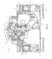
- Circuit breaker 2 includes a housing 4 having first and second side walls 6 and 7 joined by first and second end walls 9 and 10 and a face portion 12 to form an interior portion 14. Face portion 12 includes an extended region 16 that supports a manual operating toggle 20 as well as houses various tripping mechanism components as will be discussed more fully below. As will also be discussed more fully below, manual operating toggle 20 is pivotal between three positions; a connect position, a disconnect position, and a tripped position, about an axis of rotation 22.
- Circuit breaker 2 includes a first opening 25, provided on first side wall 6, and a second opening 28, provided on second side wall 7.
- An axle member 26 passes through first and second openings 25 and 28.
- Axle member 26 is configured to receive and/or transmit a mechanical trip signal to and/or from an adjacent circuit breaker (not shown).
- Circuit breaker 2 is further shown to include a first connector member 32 that is configured to connect to a load conductor (not shown), and a second connector member 34 configured to connect to a line conductor (also not shown).
- first connector member 32 may alternatively be connected to a line conductor and second connector member 34 may alternatively be connected to the load conductor.
- circuit breaker 2 includes a ground leakage test element shown in the form of a resistor 37.
- Ground leakage test element 37 simulates a ground leakage to provide a test signal to trip circuit breaker 2 upon activation of a test button 38.
- first and second connector members 32 and 34 are electrically coupled to a trigger assembly 39 having first and second trigger members 40 and 42.
- Trigger members 40 and 42 are configured to act upon electrical contacts (not shown) arranged within housing 4. The electrical contacts (not shown) are selectively connected/disconnected to pass electrical current between a source of electrical energy (not shown) and an electrical load (also not shown).
- first and second trigger members 40 and 42 are operatively connected to first and second tripping mechanisms 45 and 47.
- First tripping mechanism 45 selectively acts upon first and second trigger members 40 and 42 based on a sensed electrical anomaly such as an over current condition, a ground leakage, and/or an arc fault condition.
- Second tripping mechanism 47 selectively acts upon first and second trigger members 40 and 42 based on a received mechanical trip signal from an adjacent circuit breaker. Second tripping mechanism 47 also generates a mechanical trip signal that is passed to adjacent circuit breakers. At this point it should be understood that the phrase "act upon” includes releasing a biasing force from one, the other, or both of trigger members 40 and 42.
- first tripping mechanism 45 includes a relay 60 having an actuator 61.
- Actuator 61 is selectively extended by relay 60 upon receiving an electrical trip signal from a sensor (not separately labeled) indicating an electrical anomaly.
- the electrical anomaly may include an over current condition, a ground leakage condition and/or an arc fault condition.
- Actuator 61 acts upon a relay tripping lever 64 which, in turn, acts upon a tripping member 68.
- tripping member 68 is configured to act upon first and second trigger members 40 and 42 to move manual operating toggle to a tripped position as shown.
- Relay tripping lever 64 also acts upon a trip flag release 71 to release a trip flag 73 to provide a visual indication of a trip condition.
- Relay tripping lever 64 includes a first end section 77 that defines an axis of rotation 79. First end section 77 extends to a second end section 82 having a contact pad 83 that receives input from actuator 61. Relay tripping lever 64 also includes a first actuator member 85 and a second actuator member 87. First actuator member 85 contacts and operates tripping member 68, and second actuator member 87 acts upon trip flag release 71. More specifically, upon sensing the electrical anomaly, actuator 61 extends from relay 60 and causes relay tripping lever 64 to pivot about axis of rotation 79. As relay tripping 64 lever pivots, first actuator member 85 acts upon tripping member 68 to shift first and second trigger members 40 and 42 as will be detailed below.
- Second actuator member 87 acts upon trip flag release 71 to free trip flag 73.
- Trip flag release 71 includes a first end portion 91 that extends to a second end portion 92 through an intermediate portion 93 that defines an axis of rotation 94.
- Second end portion 92 includes a release member 96 that releases trip flag 73 to expose a visual indicator 104.
- tripping member 68 includes a central portion 108 that includes a center portion 110. Tripping member 68 further includes a first actuating element 112 and a second actuating element 113. First actuating element 112 is configured to receive an input from first actuator member 85 to pivot tripping member 68 about center portion 110. Second actuator element 113 includes a pin element 114 that is configured to activate second tripping mechanism 47. Tripping member 68 is also operatively coupled to manual operating toggle 20 through a lever member 116. Lever member 116 includes a first end (not shown) coupled to tripping member 68 and a second end 117 coupled to manual operating toggle 20 at a position off-set from axis of rotation 22.
- tripping member 68 ties together inputs received from manual operating toggle 20, first tripping mechanism 45, and second tripping mechanism 47 to selectively act upon first and second trigger members 40 and 42. More specifically, tripping member 68 selectively shifts first and second trigger members 40 and 42 through operation of manual operating toggle 20, and based on inputs received from first and second tripping mechanisms 45 and 47.
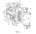
- Second tripping mechanism 47 includes a hammer 130 operatively connected to tripping member 68.
- Hammer 130 includes a first end 134 that extends to a second end 135 through an intermediate section 136.
- First end 134 defines an axis of rotation 139 for hammer 130.
- Second end portion 135 includes a pin member 141 that is configured to act upon second trigger member 42. More specifically, pin member 141 moves second trigger member 42 relative to first trigger member 40.
- Intermediate portion 136 includes an actuator portion 145 having an opening 147 that receives pin element 114.
- Actuator portion 145 also includes a contact feature 149.
- Contact feature 149 is engaged by a spring member or main spring 153.
- Main spring 153 includes a first end section 155 that extends to a second end section 156 through an intermediate section 158.
- First end section 155 is fixed relative to housing 4.
- Second end section 156 is cantilevered from a post 160 to produce a biasing force. The biasing force causes second end section 156 to act against contact feature 149 to urge pin member 141 against second trigger member 42.
- Second tripping mechanism 47 is also shown to include an external tripping element 166 ( FIG. 3 ) operatively coupled to hammer 130.
- a second external tripping element (not shown) is also mounted to an opposing side of hammer 130.
- External tripping element 166 includes a first end 170 that extends to a second end 171.
- First end 170 includes an axis of rotation (not separately labeled) that coincides with axis of rotation 139 of hammer 130 and second end 171 includes an axle receiving element 180 that is configured to receive axle member 26.
- rotation of hammer 130 is mechanically coupled to external tripping element 166 and the second external tripping element (not shown).
- a mechanical tripping signal input received at axle member 26 acts upon external tripping element 166.
- External tripping element 166 in turn acts upon hammer 130 which moves first and second trigger members 40 and 42.
- first actuator member 85 acts upon first actuating element 112 of tripping member 68 as shown in block 302. Tripping member 68 pivots causing pin element 114 to act upon actuating portion 145 of hammer 130.
- central portion 110 crosses an imaginary line that extends between pin elements 114 and second end 117 of lever member 116 allowing main spring 156 to shift hammer 130 about axis of rotation 139 as shown in block 304. Rotation of precursor 130 disengages/releases pin member 141 from second trigger member 42 in block 306 to open first and second contacts (not shown) that open an associated electrical circuit (also not shown).
- Main spring 156 generates mechanical trip signal output 182 in block 308 that shifts manual operating toggle to the tripped position- More specifically, mechanical trip signal output 182 develops a generally square wave form as a result of main spring 156 providing a biasing force to hammer 130 spaced from axis of rotation 139.
- Mechanical trip signal output 182 is also passed to external tripping element 166 to mechanically trip adjacent circuit breakers (not shown) such as shown in block 310.
- a mechanical trip signal received at external tripping element 166 is passed to hammer 130 which acts upon pin element 114. Pin element 114 rotates tripping member 68 causing central portion 110 to cross the imaginary line that extends between pin element 114 and second end 117 of lever member 116 allowing main spring 156 to force hammer 130 upward releasing second contact 42.
- mechanical trip signal 182 generated by main spring 156 has a prolonged dwell that balances on/off trip forces with on/off actuation through manual operating toggle 20.
- Circuit breakers require a specific force to be tripped such as shown at 400 in FIG. 7 .
- prior art arrangements create a sharply degrading mechanical trip signal 410 due to the spring force being provided at the axis of rotation of the precursor. Sharply degrading signal 410 quickly loses energy. As such, prior art arrangements are often incapable of dislodging contacts that may become struck together.
- the exemplary embodiments provide a trip signal having a prolonged dwell that is configured to more completely capture the force required to trip the circuit breaker.
- the prolonged dwell provides increased time and energy to the delivery or mechanical tripping force that may assist in disconnecting mechanisms that may have become stuck together.
Description
- The subject matter disclosed herein relates to the art of circuit breakers and, more particularly, to a circuit breaker tripping mechanism.
- Circuit breakers are configured to interrupt a current flow in the event of an electrical anomaly, typically an overcurrent condition. The interruption of current flow provides protection to electrical consumers as well as associated conductors and electrical loads. Generally, many circuit breakers take the form of residual current circuit breakers (RCCB). Residual current circuit breakers disconnect a circuit when an imbalance is detected between current flowing between line and neutral conductors. In many cases, residual current circuit breakers may include both overcurrent and leakage protection. More specifically, in addition to sensing overcurrent conditions, residual current circuit breakers may also be configured with earth leakage detecting circuitry that will interrupt power in the event that current is sensed leaking to ground.
-
DE 195 34 612 A1 discloses a dual circuit breaker. Primary and secondary articulated lever devices which are interlocked with one another are coupled to a first and second support arm to open both contact pairs in the vent excess current is detected. - Circuit breakers may also include internal mechanisms that receive and/or transmit mechanical tripping forces from/to another associated circuit breaker. More specifically, in a ganged circuit breaker arrangement, or an arrangement of multiple connected circuit breakers used to protect multiple phases of a multi-phase system, a trip signal resulting from an electrical fault detected on one circuit breaker is mechanically transmitted to adjacent circuit breakers. In this manner, all breakers connected to a multiple phase system are tripped even if the electrical anomaly is found in only one phase.
- The present invention is defined in the accompanying claims.
- According to one aspect of the exemplary embodiment, a circuit breaker includes a trigger assembly having first and second trigger members, and a tripping mechanism configured and disposed to act upon one of the first and second trigger members to selectively open an electrical circuit upon receipt of a mechanical trip signal input, and provide a mechanical trip signal output. The tripping mechanism includes a hammer having a first end defining an axis of rotation, a second end configured and disposed to act upon one of the first and second trigger members, and an intermediate portion spaced from each of the first and second ends. A spring member includes an end section arranged to act upon the intermediate portion of the hammer. The spring member is configured and disposed to apply a force to the intermediate portion to urge the hammer about the axis of rotation to cause the second end to disengage from the one of the first and second trigger members and open the electrical circuit.
- In accordance with another aspect of the exemplary embodiment, a circuit breaker includes a trigger assembly having first and second trigger members, and a first tripping mechanism operatively connected to the first and second trigger members. The first tripping mechanism is configured and disposed to act upon one of the first and second trigger members to open an electrical circuit. A second tripping mechanism is configured and disposed to act upon the one of the first and second trigger members to open the electrical circuit upon receipt of a mechanical trip signal input, and provide a mechanical trip signal output. The second tripping mechanism includes a hammer having a first end defining an axis of rotation, a second end configured and disposed to act upon the one of the first and second trigger members, and an intermediate portion spaced from each of the first and second ends. A spring member includes an end section arranged to act upon the intermediate portion of the hammer. The spring member is configured and disposed to apply a force to the intermediate portion to urge the hammer about the axis of rotation to cause the second end disengage from the one of the first and second trigger members and open the electrical circuit.
- According to yet another aspect of the exemplary embodiment, a method of tripping a circuit breaker includes releasing a hammer having a first end, a second end and an intermediate portion from a connected position, pivoting the hammer about an axis of rotation defined at the first end, applying a spring force to the intermediate portion of the hammer spaced from the axis of rotation, and shifting the second end of the hammer from one of first and second trigger members to open an electrical circuit.
- These and other advantages and features will become more apparent from the following description taken in conjunction with the drawings.
- The subject matter, which is regarded as the invention, is particularly pointed out and distinctly claimed in the claims at the conclusion of the specification. The foregoing and other features, and advantages of the invention are apparent from the following detailed description taken in conjunction with the accompanying drawings in which:
-
FIG. 1 is a left perspective view of a circuit breaker including a tripping mechanism shown in a connected condition in accordance with an exemplary embodiment; -
FIG. 2 is a right perspective view of the circuit breaker ofFIG. 1 shown in a disconnected condition; -
FIG. 3 is a cross-sectional side view of the circuit breaker ofFIG. 1 ; -
FIG. 4 is a detail view of the cross-sectional view ofFIG. 1 illustrating a first tripping mechanism in accordance with the exemplary embodiment shown in a tripped position; -
FIG. 5 is a detail view of the cross-sectional view ofFIG. 1 illustrating a first tripping mechanism in accordance with the exemplary embodiment shown in a tripped position; -
FIG. 6 is a detail view of the cross-sectional view ofFIG. 1 illustrating a second tripping mechanism in accordance with the exemplary embodiment shown in a non-tripped position; -
FIG. 7 is a graph illustrating a mechanical force generated by the second tripping mechanism in accordance with the exemplary embodiment; and -
FIG. 8 is a flow chart illustrating a method of operating a circuit breaker in accordance with an exemplary embodiment. - The detailed description explains embodiments of the invention, together with advantages and features, by way of example with reference to the drawings.
- A circuit breaker in accordance with an exemplary embodiment is illustrated generally at 2 in
FIGs. 1-3 .Circuit breaker 2 includes ahousing 4 having first andsecond side walls second end walls 9 and 10 and aface portion 12 to form aninterior portion 14.Face portion 12 includes an extendedregion 16 that supports amanual operating toggle 20 as well as houses various tripping mechanism components as will be discussed more fully below. As will also be discussed more fully below,manual operating toggle 20 is pivotal between three positions; a connect position, a disconnect position, and a tripped position, about an axis ofrotation 22. -
Circuit breaker 2 includes afirst opening 25, provided onfirst side wall 6, and asecond opening 28, provided onsecond side wall 7. Anaxle member 26 passes through first andsecond openings member 26 is configured to receive and/or transmit a mechanical trip signal to and/or from an adjacent circuit breaker (not shown).Circuit breaker 2 is further shown to include afirst connector member 32 that is configured to connect to a load conductor (not shown), and asecond connector member 34 configured to connect to a line conductor (also not shown). At this point it should be understood thatfirst connector member 32 may alternatively be connected to a line conductor andsecond connector member 34 may alternatively be connected to the load conductor. In addition to the above,circuit breaker 2 includes a ground leakage test element shown in the form of aresistor 37. Groundleakage test element 37 simulates a ground leakage to provide a test signal totrip circuit breaker 2 upon activation of atest button 38. - Regardless of configuration, first and
second connector members trigger assembly 39 having first andsecond trigger members Trigger members housing 4. The electrical contacts (not shown) are selectively connected/disconnected to pass electrical current between a source of electrical energy (not shown) and an electrical load (also not shown). As will become more readily apparent below, first andsecond trigger members second tripping mechanisms First tripping mechanism 45 selectively acts upon first andsecond trigger members Second tripping mechanism 47 selectively acts upon first andsecond trigger members Second tripping mechanism 47 also generates a mechanical trip signal that is passed to adjacent circuit breakers. At this point it should be understood that the phrase "act upon" includes releasing a biasing force from one, the other, or both oftrigger members - Reference will now be made to
FIG. 4 in describingfirst tripping mechanism 45. As shown,first tripping mechanism 45 includes arelay 60 having anactuator 61.Actuator 61 is selectively extended byrelay 60 upon receiving an electrical trip signal from a sensor (not separately labeled) indicating an electrical anomaly. As discussed above, the electrical anomaly may include an over current condition, a ground leakage condition and/or an arc fault condition.Actuator 61 acts upon arelay tripping lever 64 which, in turn, acts upon atripping member 68. As will be detailed more fully below, trippingmember 68 is configured to act upon first andsecond trigger members lever 64 also acts upon atrip flag release 71 to release atrip flag 73 to provide a visual indication of a trip condition. - Relay tripping
lever 64 includes afirst end section 77 that defines an axis ofrotation 79.First end section 77 extends to asecond end section 82 having acontact pad 83 that receives input fromactuator 61. Relay trippinglever 64 also includes afirst actuator member 85 and asecond actuator member 87.First actuator member 85 contacts and operates trippingmember 68, andsecond actuator member 87 acts upontrip flag release 71. More specifically, upon sensing the electrical anomaly,actuator 61 extends fromrelay 60 and causes relay trippinglever 64 to pivot about axis ofrotation 79. As relay tripping 64 lever pivots,first actuator member 85 acts upon trippingmember 68 to shift first andsecond trigger members Second actuator member 87 acts upontrip flag release 71 tofree trip flag 73.Trip flag release 71 includes afirst end portion 91 that extends to asecond end portion 92 through anintermediate portion 93 that defines an axis ofrotation 94.Second end portion 92 includes arelease member 96 that releasestrip flag 73 to expose avisual indicator 104. - In further accordance with the exemplary embodiment, tripping
member 68 includes acentral portion 108 that includes acenter portion 110. Trippingmember 68 further includes afirst actuating element 112 and asecond actuating element 113.First actuating element 112 is configured to receive an input fromfirst actuator member 85 to pivot trippingmember 68 aboutcenter portion 110.Second actuator element 113 includes apin element 114 that is configured to activate second trippingmechanism 47. Trippingmember 68 is also operatively coupled tomanual operating toggle 20 through alever member 116.Lever member 116 includes a first end (not shown) coupled to trippingmember 68 and asecond end 117 coupled tomanual operating toggle 20 at a position off-set from axis ofrotation 22. - With this arrangement, tripping
member 68 ties together inputs received frommanual operating toggle 20, first trippingmechanism 45, and second trippingmechanism 47 to selectively act upon first andsecond trigger members member 68 selectively shifts first andsecond trigger members manual operating toggle 20, and based on inputs received from first and second trippingmechanisms - Reference will now be made to
FIG.s 5 and6 in describing second trippingmechanism 47 in accordance with an exemplary embodiment. Second trippingmechanism 47 includes ahammer 130 operatively connected to trippingmember 68.Hammer 130 includes afirst end 134 that extends to asecond end 135 through anintermediate section 136.First end 134 defines an axis ofrotation 139 forhammer 130.Second end portion 135 includes apin member 141 that is configured to act uponsecond trigger member 42. More specifically,pin member 141 movessecond trigger member 42 relative tofirst trigger member 40.Intermediate portion 136 includes anactuator portion 145 having anopening 147 that receivespin element 114.Actuator portion 145 also includes acontact feature 149. -
Contact feature 149 is engaged by a spring member ormain spring 153.Main spring 153 includes afirst end section 155 that extends to asecond end section 156 through anintermediate section 158.First end section 155 is fixed relative tohousing 4.Second end section 156 is cantilevered from apost 160 to produce a biasing force. The biasing force causessecond end section 156 to act againstcontact feature 149 to urgepin member 141 againstsecond trigger member 42. Second trippingmechanism 47 is also shown to include an external tripping element 166 (FIG. 3 ) operatively coupled to hammer 130. A second external tripping element (not shown) is also mounted to an opposing side ofhammer 130. External trippingelement 166 includes afirst end 170 that extends to asecond end 171.First end 170 includes an axis of rotation (not separately labeled) that coincides with axis ofrotation 139 ofhammer 130 andsecond end 171 includes anaxle receiving element 180 that is configured to receiveaxle member 26. With this arrangement, rotation ofhammer 130 is mechanically coupled to external trippingelement 166 and the second external tripping element (not shown). As will be detailed more fully below, a mechanical tripping signal input received ataxle member 26 acts upon external trippingelement 166. External trippingelement 166 in turn acts uponhammer 130 which moves first andsecond trigger members hammer 130 resulting from a sensed over current condition will generate a force or mechanical energy that provides a mechanicaltrip signal output 182, illustrated inFIG. 7 , at external trippingelement 166 and the second external tripping element (not shown). Mechanicaltrip signal output 182 is transmitted to adjacent circuit breakers (also not shown) throughaxle member 26. - In accordance with the exemplary embodiment, upon sensing an electrical anomaly as discussed above and shown in
block 300 inFIG. 8 ,first actuator member 85 acts uponfirst actuating element 112 of trippingmember 68 as shown inblock 302. Trippingmember 68 pivots causingpin element 114 to act upon actuatingportion 145 ofhammer 130. In addition,central portion 110 crosses an imaginary line that extends betweenpin elements 114 andsecond end 117 oflever member 116 allowingmain spring 156 to shifthammer 130 about axis ofrotation 139 as shown inblock 304. Rotation ofprecursor 130 disengages/releasespin member 141 fromsecond trigger member 42 inblock 306 to open first and second contacts (not shown) that open an associated electrical circuit (also not shown).Main spring 156 generates mechanicaltrip signal output 182 inblock 308 that shifts manual operating toggle to the tripped position- More specifically, mechanicaltrip signal output 182 develops a generally square wave form as a result ofmain spring 156 providing a biasing force to hammer 130 spaced from axis ofrotation 139. Mechanicaltrip signal output 182 is also passed to external trippingelement 166 to mechanically trip adjacent circuit breakers (not shown) such as shown inblock 310. Similarly, a mechanical trip signal received at external trippingelement 166 is passed to hammer 130 which acts uponpin element 114.Pin element 114 rotates trippingmember 68 causingcentral portion 110 to cross the imaginary line that extends betweenpin element 114 andsecond end 117 oflever member 116 allowingmain spring 156 to forcehammer 130 upward releasingsecond contact 42. - In either case, mechanical trip signal 182 generated by
main spring 156 has a prolonged dwell that balances on/off trip forces with on/off actuation throughmanual operating toggle 20. Circuit breakers require a specific force to be tripped such as shown at 400 inFIG. 7 . In contrast prior art arrangements create a sharply degrading mechanical trip signal 410 due to the spring force being provided at the axis of rotation of the precursor. Sharply degradingsignal 410 quickly loses energy. As such, prior art arrangements are often incapable of dislodging contacts that may become struck together. The exemplary embodiments provide a trip signal having a prolonged dwell that is configured to more completely capture the force required to trip the circuit breaker. In addition to balancing on/off trip forces with on/off actuation forces, the prolonged dwell provides increased time and energy to the delivery or mechanical tripping force that may assist in disconnecting mechanisms that may have become stuck together.
Claims (20)
- A circuit breaker (2) comprising:a trigger assembly (39) having first and second trigger members (40,42); anda tripping mechanism (47) configured and disposed to act upon the first and second trigger members (40,42)to selectively open an electrical circuit upon receipt of a mechanical trip signal input, and to provide a mechanical trip signal output, the tripping mechanism including a hammer (130) having a first end (134) defining an axis of rotation (139), a second end (135) configured and disposed to act upon one of the first and second trigger members and an intermediate portion (136) spaced from each of the first and second ends (134,135), and a spring member (153) including an end section (156) arranged to act upon the intermediate portion of the hammer (136), characterised by the spring member (153) being configured and disposed to apply a force to the intermediate portion (136) to urge the hammer (130) about the axis of rotation (139) to cause the second end (135) to disengage from the one of the first and second trigger members (40,42).
- The circuit breaker according to claim 1 further comprising: a tripping member (68) operatively connected to the tripping mechanism, the tripping member being configured and disposed to act upon the hammer (130).
- The circuit breaker according to claim 2, further comprising: a manual operating toggle (20) operatively connected to the tripping member (68), the manual operating toggle being configured and disposed to provide a manual operation of the tripping mechanism (47).
- The circuit breaker according to claim 1, further comprising: an external tripping clement (166) operatively connected to the hammer, the external tripping element being configured and disposed to provide the mechanical trip signal output.
- The circuit breaker according to claim 4 further comprising: an axle element (26) operatively connected to the external tripping element (166), the axle element being configured and disposed to transmit the mechanical trip signal output to another circuit breaker.
- The circuit breaker according to claim 4 wherein the mechanical trip signal output provided by the tripping mechanism includes a generally square waveform produced by the spring member.
- A circuit breaker (2) comprising:a trigger assembly (39) having first and second trigger members (40,42);a first tripping mechanism(45) operatively connected to the first trigger member and the second trigger member, the first tripping mechanism being configured and disposed to operate the trigger assembly (39) to selectively disconnect first and second contacts; anda second tripping mechanism (47) configured and disposed to operate the trigger assembly (39) upon receipt of a mechanical trip signal input, and provide a mechanical trip signal output, the second tripping mechanism (47) including a hammer (130) having a first end (134) defining an axis of rotation (139), a second end (135) configured and disposed to act upon one of the first and second trigger members (40,42) and an intermediate portion (136) spaced from each of the first and second ends (134,135), and a spring member (153) including an end section (156) arranged to act upon the intermediate portion of the hammer (136), the spring member (153) being configured and disposed to apply a force to the intermediate portion ((136) to urge the hammer (130) about the axis of rotation (139) to cause the second end (135) to disengage from the one of the first and second trigger members (40,42).
- The circuit breaker according to claim 7, further comprising: a tripping member (68) operatively connected to each of the first tripping mechanism and the second tripping mechanism, the tripping member being configured and disposed to act upon the hammer (130).
- The circuit breaker according to claim 8, wherein the first tripping mechanism (45) includes a relay having an actuator, and a tripping lever pivotally mounted between the actuator and the tripping member.
- The circuit breaker according to claim 8, further comprising: a manual operating toggle operatively connected to the tripping member, the manual operating toggle being configured and disposed to provide a manual operation of one of the first and second tripping mechanisms.
- The circuit breaker according to claim 7, further comprising: a flag release (71) operatively connected to a trip flag (73), the trip flag providing a visual indication of a trip condition of the first and second tripping mechanisms.
- The circuit breaker according to claim 7, further comprising: an external tripping element (166) operatively connected to the hammer (130), the external tripping element being configured and disposed to provide the mechanical trip signal output.
- The circuit breaker according to claim 12, further comprising: an axle element (26) operatively connected to the external tripping element, the axle element being configured and disposed to transmit the mechanical trip signal output to another circuit breaker.
- The circuit breaker according to claim 7, wherein the mechanical trip signal output includes a generally square waveform produced by the spring member.
- A method of tripping a circuit breaker according to claim 1 or 7, the method comprising:releasing a hammer (130) having a first end (134), a second end (135) and an intermediate portion (136) from a connected position;pivoting the hammer (130) about an axis of rotation (139) defined at the first end (134);applying a spring force to the intermediate portion of the hammer (136) spaced from the axis of rotation (139); andshifting the second end of the hammer (135) from one of first and second trigger members (40,42) to open an electrical circuit.
- The method of claim 15, further comprising: providing a mechanical trip signal output from the hammer.
- The method of claim 16, further comprising: transmitting the mechanical trip signal output to another circuit breaker.
- The method of claim 15, wherein releasing the hammer includes receiving a mechanical trip signal input from another circuit breaker at the hammer.
- The method of claim 15, wherein releasing the hammer includes receiving a trip signal from a relay in the circuit breaker.
- The method of claim 15, wherein releasing the hammer includes receiving an open command from a manual operating toggle of the circuit breaker.
Priority Applications (2)
| Application Number | Priority Date | Filing Date | Title |
|---|---|---|---|
| EP12382222.3A EP2669923B1 (en) | 2012-06-01 | 2012-06-01 | Circuit breaker and method of tripping a circuit breaker |
| CN201310215734.7A CN103456572B (en) | 2012-06-01 | 2013-05-31 | Circuit-breaker and the method making circuit breaker trip |
Applications Claiming Priority (1)
| Application Number | Priority Date | Filing Date | Title |
|---|---|---|---|
| EP12382222.3A EP2669923B1 (en) | 2012-06-01 | 2012-06-01 | Circuit breaker and method of tripping a circuit breaker |
Publications (2)
| Publication Number | Publication Date |
|---|---|
| EP2669923A1 EP2669923A1 (en) | 2013-12-04 |
| EP2669923B1 true EP2669923B1 (en) | 2015-09-02 |
Family
ID=46201533
Family Applications (1)
| Application Number | Title | Priority Date | Filing Date |
|---|---|---|---|
| EP12382222.3A Active EP2669923B1 (en) | 2012-06-01 | 2012-06-01 | Circuit breaker and method of tripping a circuit breaker |
Country Status (2)
| Country | Link |
|---|---|
| EP (1) | EP2669923B1 (en) |
| CN (1) | CN103456572B (en) |
Families Citing this family (2)
| Publication number | Priority date | Publication date | Assignee | Title |
|---|---|---|---|---|
| ES2946269T3 (en) * | 2018-04-23 | 2023-07-14 | Abb Spa | circuit breaker |
| JP2020167089A (en) * | 2019-03-29 | 2020-10-08 | パナソニックIpマネジメント株式会社 | Circuit breaker |
Family Cites Families (6)
| Publication number | Priority date | Publication date | Assignee | Title |
|---|---|---|---|---|
| JP2756481B2 (en) * | 1994-10-21 | 1998-05-25 | サンケン・エアパクス株式会社 | Circuit breaker |
| DE19933166A1 (en) * | 1999-07-14 | 2001-01-18 | Hager Electro Gmbh | Activating and deactivating device for mains protective switches arranged in block, has device for removing support parts from members which transfer closing force for switching contacts |
| US6864450B1 (en) * | 2004-05-19 | 2005-03-08 | Eaton Corporation | Circuit breaker with delay mechanism |
| KR100876408B1 (en) * | 2007-07-12 | 2008-12-31 | 엘에스산전 주식회사 | Air circuit breaker with mechanical trip indicating mechanism |
| IT1398379B1 (en) * | 2010-02-23 | 2013-02-22 | Bticino Spa | INTERLOCK DEVICE TO INTERLOCK AT LEAST ONE FIRST AND ONE SECOND ELECTRIC SWITCH. |
| DE102010019741B4 (en) * | 2010-05-07 | 2022-05-05 | Siemens Aktiengesellschaft | Switching mechanism for a residual current circuit breaker and residual current circuit breaker |
-
2012
- 2012-06-01 EP EP12382222.3A patent/EP2669923B1/en active Active
-
2013
- 2013-05-31 CN CN201310215734.7A patent/CN103456572B/en active Active
Also Published As
| Publication number | Publication date |
|---|---|
| CN103456572B (en) | 2016-12-28 |
| EP2669923A1 (en) | 2013-12-04 |
| CN103456572A (en) | 2013-12-18 |
Similar Documents
| Publication | Publication Date | Title |
|---|---|---|
| US6538862B1 (en) | Circuit breaker with a single test button mechanism | |
| US6259340B1 (en) | Circuit breaker with a dual test button mechanism | |
| US7656640B2 (en) | Voltage surge protection device | |
| US8369052B2 (en) | Modular circuit breaker | |
| EP1814133B1 (en) | Circuit breaking apparatus | |
| US9928977B2 (en) | Electrical switching apparatus, and operating handle assembly and trip cam therefor | |
| US9024711B2 (en) | Thermal-magnetic trip device for tripping a multiphase circuit breaker | |
| EP2455961B1 (en) | Electric switching device | |
| EP2242080B1 (en) | Test assembly for a circuit breaker | |
| EP3621097B1 (en) | Circuit breaker with slide to test function | |
| CA2744966A1 (en) | Switching apparatus comprising a plurality of switching assemblies, and associated method | |
| EP2669923B1 (en) | Circuit breaker and method of tripping a circuit breaker | |
| CN101361243B (en) | Protective device having a circuit breaker, in particular a low-voltage circuit breaker | |
| US9852857B2 (en) | Electrical switching apparatus and contact assembly therefor | |
| EP3292558B1 (en) | Electrical switching apparatus and trip assembly therefor | |
| JP4921931B2 (en) | Circuit breaker | |
| KR101537679B1 (en) | Device for displaying of contact in circuit breaker | |
| KR200181711Y1 (en) | The indicating device of the trip for circuit breakers | |
| CN102210001B (en) | Fuse board | |
| KR200441578Y1 (en) | Alarm device for circuit breaker | |
| EP3048632B1 (en) | Method for operating a circuit breaker and circuit breaker | |
| NZ755968B2 (en) | Circuit Breaker with Slide to Test Function | |
| KR20000001452U (en) | Device to check normal operation of wiring breaker |
Legal Events
| Date | Code | Title | Description |
|---|---|---|---|
| PUAI | Public reference made under article 153(3) epc to a published international application that has entered the european phase |
Free format text: ORIGINAL CODE: 0009012 |
|
| AK | Designated contracting states |
Kind code of ref document: A1 Designated state(s): AL AT BE BG CH CY CZ DE DK EE ES FI FR GB GR HR HU IE IS IT LI LT LU LV MC MK MT NL NO PL PT RO RS SE SI SK SM TR |
|
| AX | Request for extension of the european patent |
Extension state: BA ME |
|
| 17P | Request for examination filed |
Effective date: 20140612 |
|
| RBV | Designated contracting states (corrected) |
Designated state(s): AL AT BE BG CH CY CZ DE DK EE ES FI FR GB GR HR HU IE IS IT LI LT LU LV MC MK MT NL NO PL PT RO RS SE SI SK SM TR |
|
| GRAP | Despatch of communication of intention to grant a patent |
Free format text: ORIGINAL CODE: EPIDOSNIGR1 |
|
| RIC1 | Information provided on ipc code assigned before grant |
Ipc: H01H 71/10 20060101AFI20150318BHEP Ipc: H01H 73/12 20060101ALN20150318BHEP Ipc: H01H 71/52 20060101ALN20150318BHEP Ipc: H01H 3/46 20060101ALN20150318BHEP Ipc: H01H 83/04 20060101ALN20150318BHEP |
|
| INTG | Intention to grant announced |
Effective date: 20150402 |
|
| GRAS | Grant fee paid |
Free format text: ORIGINAL CODE: EPIDOSNIGR3 |
|
| GRAA | (expected) grant |
Free format text: ORIGINAL CODE: 0009210 |
|
| AK | Designated contracting states |
Kind code of ref document: B1 Designated state(s): AL AT BE BG CH CY CZ DE DK EE ES FI FR GB GR HR HU IE IS IT LI LT LU LV MC MK MT NL NO PL PT RO RS SE SI SK SM TR |
|
| REG | Reference to a national code |
Ref country code: GB Ref legal event code: FG4D |
|
| REG | Reference to a national code |
Ref country code: AT Ref legal event code: REF Ref document number: 747084 Country of ref document: AT Kind code of ref document: T Effective date: 20150915 Ref country code: CH Ref legal event code: EP |
|
| REG | Reference to a national code |
Ref country code: IE Ref legal event code: FG4D |
|
| REG | Reference to a national code |
Ref country code: DE Ref legal event code: R096 Ref document number: 602012010203 Country of ref document: DE |
|
| REG | Reference to a national code |
Ref country code: AT Ref legal event code: MK05 Ref document number: 747084 Country of ref document: AT Kind code of ref document: T Effective date: 20150902 |
|
| PG25 | Lapsed in a contracting state [announced via postgrant information from national office to epo] |
Ref country code: GR Free format text: LAPSE BECAUSE OF FAILURE TO SUBMIT A TRANSLATION OF THE DESCRIPTION OR TO PAY THE FEE WITHIN THE PRESCRIBED TIME-LIMIT Effective date: 20151203 Ref country code: NO Free format text: LAPSE BECAUSE OF FAILURE TO SUBMIT A TRANSLATION OF THE DESCRIPTION OR TO PAY THE FEE WITHIN THE PRESCRIBED TIME-LIMIT Effective date: 20151202 Ref country code: FI Free format text: LAPSE BECAUSE OF FAILURE TO SUBMIT A TRANSLATION OF THE DESCRIPTION OR TO PAY THE FEE WITHIN THE PRESCRIBED TIME-LIMIT Effective date: 20150902 Ref country code: LT Free format text: LAPSE BECAUSE OF FAILURE TO SUBMIT A TRANSLATION OF THE DESCRIPTION OR TO PAY THE FEE WITHIN THE PRESCRIBED TIME-LIMIT Effective date: 20150902 Ref country code: LV Free format text: LAPSE BECAUSE OF FAILURE TO SUBMIT A TRANSLATION OF THE DESCRIPTION OR TO PAY THE FEE WITHIN THE PRESCRIBED TIME-LIMIT Effective date: 20150902 |
|
| REG | Reference to a national code |
Ref country code: LT Ref legal event code: MG4D Ref country code: NL Ref legal event code: MP Effective date: 20150902 |
|
| PG25 | Lapsed in a contracting state [announced via postgrant information from national office to epo] |
Ref country code: SE Free format text: LAPSE BECAUSE OF FAILURE TO SUBMIT A TRANSLATION OF THE DESCRIPTION OR TO PAY THE FEE WITHIN THE PRESCRIBED TIME-LIMIT Effective date: 20150902 Ref country code: RS Free format text: LAPSE BECAUSE OF FAILURE TO SUBMIT A TRANSLATION OF THE DESCRIPTION OR TO PAY THE FEE WITHIN THE PRESCRIBED TIME-LIMIT Effective date: 20150902 Ref country code: AT Free format text: LAPSE BECAUSE OF FAILURE TO SUBMIT A TRANSLATION OF THE DESCRIPTION OR TO PAY THE FEE WITHIN THE PRESCRIBED TIME-LIMIT Effective date: 20150902 Ref country code: PL Free format text: LAPSE BECAUSE OF FAILURE TO SUBMIT A TRANSLATION OF THE DESCRIPTION OR TO PAY THE FEE WITHIN THE PRESCRIBED TIME-LIMIT Effective date: 20150902 Ref country code: ES Free format text: LAPSE BECAUSE OF FAILURE TO SUBMIT A TRANSLATION OF THE DESCRIPTION OR TO PAY THE FEE WITHIN THE PRESCRIBED TIME-LIMIT Effective date: 20150902 |
|
| PG25 | Lapsed in a contracting state [announced via postgrant information from national office to epo] |
Ref country code: IS Free format text: LAPSE BECAUSE OF FAILURE TO SUBMIT A TRANSLATION OF THE DESCRIPTION OR TO PAY THE FEE WITHIN THE PRESCRIBED TIME-LIMIT Effective date: 20160102 Ref country code: NL Free format text: LAPSE BECAUSE OF FAILURE TO SUBMIT A TRANSLATION OF THE DESCRIPTION OR TO PAY THE FEE WITHIN THE PRESCRIBED TIME-LIMIT Effective date: 20150902 Ref country code: CZ Free format text: LAPSE BECAUSE OF FAILURE TO SUBMIT A TRANSLATION OF THE DESCRIPTION OR TO PAY THE FEE WITHIN THE PRESCRIBED TIME-LIMIT Effective date: 20150902 Ref country code: EE Free format text: LAPSE BECAUSE OF FAILURE TO SUBMIT A TRANSLATION OF THE DESCRIPTION OR TO PAY THE FEE WITHIN THE PRESCRIBED TIME-LIMIT Effective date: 20150902 Ref country code: SK Free format text: LAPSE BECAUSE OF FAILURE TO SUBMIT A TRANSLATION OF THE DESCRIPTION OR TO PAY THE FEE WITHIN THE PRESCRIBED TIME-LIMIT Effective date: 20150902 |
|
| PG25 | Lapsed in a contracting state [announced via postgrant information from national office to epo] |
Ref country code: PT Free format text: LAPSE BECAUSE OF FAILURE TO SUBMIT A TRANSLATION OF THE DESCRIPTION OR TO PAY THE FEE WITHIN THE PRESCRIBED TIME-LIMIT Effective date: 20160104 Ref country code: RO Free format text: LAPSE BECAUSE OF FAILURE TO SUBMIT A TRANSLATION OF THE DESCRIPTION OR TO PAY THE FEE WITHIN THE PRESCRIBED TIME-LIMIT Effective date: 20150902 |
|
| REG | Reference to a national code |
Ref country code: DE Ref legal event code: R097 Ref document number: 602012010203 Country of ref document: DE |
|
| REG | Reference to a national code |
Ref country code: FR Ref legal event code: PLFP Year of fee payment: 5 |
|
| PLBE | No opposition filed within time limit |
Free format text: ORIGINAL CODE: 0009261 |
|
| STAA | Information on the status of an ep patent application or granted ep patent |
Free format text: STATUS: NO OPPOSITION FILED WITHIN TIME LIMIT |
|
| 26N | No opposition filed |
Effective date: 20160603 |
|
| PG25 | Lapsed in a contracting state [announced via postgrant information from national office to epo] |
Ref country code: DK Free format text: LAPSE BECAUSE OF FAILURE TO SUBMIT A TRANSLATION OF THE DESCRIPTION OR TO PAY THE FEE WITHIN THE PRESCRIBED TIME-LIMIT Effective date: 20150902 Ref country code: SI Free format text: LAPSE BECAUSE OF FAILURE TO SUBMIT A TRANSLATION OF THE DESCRIPTION OR TO PAY THE FEE WITHIN THE PRESCRIBED TIME-LIMIT Effective date: 20150902 |
|
| PG25 | Lapsed in a contracting state [announced via postgrant information from national office to epo] |
Ref country code: BE Free format text: LAPSE BECAUSE OF FAILURE TO SUBMIT A TRANSLATION OF THE DESCRIPTION OR TO PAY THE FEE WITHIN THE PRESCRIBED TIME-LIMIT Effective date: 20150902 |
|
| PG25 | Lapsed in a contracting state [announced via postgrant information from national office to epo] |
Ref country code: MC Free format text: LAPSE BECAUSE OF FAILURE TO SUBMIT A TRANSLATION OF THE DESCRIPTION OR TO PAY THE FEE WITHIN THE PRESCRIBED TIME-LIMIT Effective date: 20150902 |
|
| REG | Reference to a national code |
Ref country code: CH Ref legal event code: PL |
|
| GBPC | Gb: european patent ceased through non-payment of renewal fee |
Effective date: 20160601 |
|
| REG | Reference to a national code |
Ref country code: IE Ref legal event code: MM4A |
|
| PG25 | Lapsed in a contracting state [announced via postgrant information from national office to epo] |
Ref country code: CH Free format text: LAPSE BECAUSE OF NON-PAYMENT OF DUE FEES Effective date: 20160630 Ref country code: LI Free format text: LAPSE BECAUSE OF NON-PAYMENT OF DUE FEES Effective date: 20160630 |
|
| PG25 | Lapsed in a contracting state [announced via postgrant information from national office to epo] |
Ref country code: IE Free format text: LAPSE BECAUSE OF NON-PAYMENT OF DUE FEES Effective date: 20160601 Ref country code: GB Free format text: LAPSE BECAUSE OF NON-PAYMENT OF DUE FEES Effective date: 20160601 |
|
| REG | Reference to a national code |
Ref country code: FR Ref legal event code: PLFP Year of fee payment: 6 |
|
| PG25 | Lapsed in a contracting state [announced via postgrant information from national office to epo] |
Ref country code: CY Free format text: LAPSE BECAUSE OF FAILURE TO SUBMIT A TRANSLATION OF THE DESCRIPTION OR TO PAY THE FEE WITHIN THE PRESCRIBED TIME-LIMIT Effective date: 20150902 Ref country code: SM Free format text: LAPSE BECAUSE OF FAILURE TO SUBMIT A TRANSLATION OF THE DESCRIPTION OR TO PAY THE FEE WITHIN THE PRESCRIBED TIME-LIMIT Effective date: 20150902 Ref country code: HU Free format text: LAPSE BECAUSE OF FAILURE TO SUBMIT A TRANSLATION OF THE DESCRIPTION OR TO PAY THE FEE WITHIN THE PRESCRIBED TIME-LIMIT; INVALID AB INITIO Effective date: 20120601 |
|
| REG | Reference to a national code |
Ref country code: FR Ref legal event code: PLFP Year of fee payment: 7 |
|
| PG25 | Lapsed in a contracting state [announced via postgrant information from national office to epo] |
Ref country code: HR Free format text: LAPSE BECAUSE OF FAILURE TO SUBMIT A TRANSLATION OF THE DESCRIPTION OR TO PAY THE FEE WITHIN THE PRESCRIBED TIME-LIMIT Effective date: 20150902 Ref country code: LU Free format text: LAPSE BECAUSE OF NON-PAYMENT OF DUE FEES Effective date: 20160601 Ref country code: TR Free format text: LAPSE BECAUSE OF FAILURE TO SUBMIT A TRANSLATION OF THE DESCRIPTION OR TO PAY THE FEE WITHIN THE PRESCRIBED TIME-LIMIT Effective date: 20150902 Ref country code: MT Free format text: LAPSE BECAUSE OF NON-PAYMENT OF DUE FEES Effective date: 20160630 Ref country code: MK Free format text: LAPSE BECAUSE OF FAILURE TO SUBMIT A TRANSLATION OF THE DESCRIPTION OR TO PAY THE FEE WITHIN THE PRESCRIBED TIME-LIMIT Effective date: 20150902 |
|
| PG25 | Lapsed in a contracting state [announced via postgrant information from national office to epo] |
Ref country code: BG Free format text: LAPSE BECAUSE OF FAILURE TO SUBMIT A TRANSLATION OF THE DESCRIPTION OR TO PAY THE FEE WITHIN THE PRESCRIBED TIME-LIMIT Effective date: 20150902 |
|
| PG25 | Lapsed in a contracting state [announced via postgrant information from national office to epo] |
Ref country code: AL Free format text: LAPSE BECAUSE OF FAILURE TO SUBMIT A TRANSLATION OF THE DESCRIPTION OR TO PAY THE FEE WITHIN THE PRESCRIBED TIME-LIMIT Effective date: 20150902 |
|
| REG | Reference to a national code |
Ref country code: DE Ref legal event code: R081 Ref document number: 602012010203 Country of ref document: DE Owner name: ABB SCHWEIZ AG, CH Free format text: FORMER OWNER: GENERAL ELECTRIC COMPANY, SCHENECTADY, N.Y., US |
|
| PGFP | Annual fee paid to national office [announced via postgrant information from national office to epo] |
Ref country code: FR Payment date: 20230627 Year of fee payment: 12 Ref country code: DE Payment date: 20230620 Year of fee payment: 12 |
|
| PGFP | Annual fee paid to national office [announced via postgrant information from national office to epo] |
Ref country code: IT Payment date: 20230623 Year of fee payment: 12 |