EP2669887A2 - Dispositif et procédé d'affichage sur écran - Google Patents
Dispositif et procédé d'affichage sur écran Download PDFInfo
- Publication number
- EP2669887A2 EP2669887A2 EP13275119.9A EP13275119A EP2669887A2 EP 2669887 A2 EP2669887 A2 EP 2669887A2 EP 13275119 A EP13275119 A EP 13275119A EP 2669887 A2 EP2669887 A2 EP 2669887A2
- Authority
- EP
- European Patent Office
- Prior art keywords
- image
- data
- osd
- line width
- width
- Prior art date
- Legal status (The legal status is an assumption and is not a legal conclusion. Google has not performed a legal analysis and makes no representation as to the accuracy of the status listed.)
- Withdrawn
Links
- 238000000034 method Methods 0.000 title claims description 30
- 230000003247 decreasing effect Effects 0.000 claims description 5
- 238000005516 engineering process Methods 0.000 abstract description 4
- 230000008569 process Effects 0.000 description 5
- 230000008901 benefit Effects 0.000 description 2
- 239000000470 constituent Substances 0.000 description 2
- 230000008859 change Effects 0.000 description 1
- 239000003086 colorant Substances 0.000 description 1
- 238000013500 data storage Methods 0.000 description 1
- 230000000694 effects Effects 0.000 description 1
- 230000007717 exclusion Effects 0.000 description 1
- 230000006870 function Effects 0.000 description 1
- 239000004973 liquid crystal related substance Substances 0.000 description 1
- 238000012986 modification Methods 0.000 description 1
- 230000004048 modification Effects 0.000 description 1
- 230000003068 static effect Effects 0.000 description 1
Images

Classifications
-
- H—ELECTRICITY
- H04—ELECTRIC COMMUNICATION TECHNIQUE
- H04N—PICTORIAL COMMUNICATION, e.g. TELEVISION
- H04N5/00—Details of television systems
- H04N5/222—Studio circuitry; Studio devices; Studio equipment
- H04N5/262—Studio circuits, e.g. for mixing, switching-over, change of character of image, other special effects ; Cameras specially adapted for the electronic generation of special effects
- H04N5/265—Mixing
-
- H—ELECTRICITY
- H04—ELECTRIC COMMUNICATION TECHNIQUE
- H04N—PICTORIAL COMMUNICATION, e.g. TELEVISION
- H04N7/00—Television systems
- H04N7/18—Closed-circuit television [CCTV] systems, i.e. systems in which the video signal is not broadcast
-
- G—PHYSICS
- G09—EDUCATION; CRYPTOGRAPHY; DISPLAY; ADVERTISING; SEALS
- G09G—ARRANGEMENTS OR CIRCUITS FOR CONTROL OF INDICATING DEVICES USING STATIC MEANS TO PRESENT VARIABLE INFORMATION
- G09G5/00—Control arrangements or circuits for visual indicators common to cathode-ray tube indicators and other visual indicators
- G09G5/003—Details of a display terminal, the details relating to the control arrangement of the display terminal and to the interfaces thereto
-
- H—ELECTRICITY
- H04—ELECTRIC COMMUNICATION TECHNIQUE
- H04N—PICTORIAL COMMUNICATION, e.g. TELEVISION
- H04N5/00—Details of television systems
- H04N5/222—Studio circuitry; Studio devices; Studio equipment
- H04N5/262—Studio circuits, e.g. for mixing, switching-over, change of character of image, other special effects ; Cameras specially adapted for the electronic generation of special effects
-
- H—ELECTRICITY
- H04—ELECTRIC COMMUNICATION TECHNIQUE
- H04N—PICTORIAL COMMUNICATION, e.g. TELEVISION
- H04N7/00—Television systems
- H04N7/14—Systems for two-way working
- H04N7/141—Systems for two-way working between two video terminals, e.g. videophone
- H04N7/147—Communication arrangements, e.g. identifying the communication as a video-communication, intermediate storage of the signals
-
- G—PHYSICS
- G09—EDUCATION; CRYPTOGRAPHY; DISPLAY; ADVERTISING; SEALS
- G09G—ARRANGEMENTS OR CIRCUITS FOR CONTROL OF INDICATING DEVICES USING STATIC MEANS TO PRESENT VARIABLE INFORMATION
- G09G2340/00—Aspects of display data processing
- G09G2340/04—Changes in size, position or resolution of an image
- G09G2340/0407—Resolution change, inclusive of the use of different resolutions for different screen areas
-
- G—PHYSICS
- G09—EDUCATION; CRYPTOGRAPHY; DISPLAY; ADVERTISING; SEALS
- G09G—ARRANGEMENTS OR CIRCUITS FOR CONTROL OF INDICATING DEVICES USING STATIC MEANS TO PRESENT VARIABLE INFORMATION
- G09G2340/00—Aspects of display data processing
- G09G2340/10—Mixing of images, i.e. displayed pixel being the result of an operation, e.g. adding, on the corresponding input pixels
-
- G—PHYSICS
- G09—EDUCATION; CRYPTOGRAPHY; DISPLAY; ADVERTISING; SEALS
- G09G—ARRANGEMENTS OR CIRCUITS FOR CONTROL OF INDICATING DEVICES USING STATIC MEANS TO PRESENT VARIABLE INFORMATION
- G09G2340/00—Aspects of display data processing
- G09G2340/12—Overlay of images, i.e. displayed pixel being the result of switching between the corresponding input pixels
Definitions
- the present invention relates to an on-screen display (OSD) device and an OSD display method.
- OSD on-screen display
- Patent Document 1 Patent Document 1
- Patent Document 2 Patent Document 3
- Patent Document 3 various technologies related to an on-screen display
- FIG. 1 is a view schematically showing an OSD image according to the related art.
- the OSD image is output as it is in a state in which it is not interpolated, a phenomenon that a line is roughly displayed may be confirmed in a region denoted by a reference numeral 2, a region denoted by a reference numeral 3, and the like.
- This unnatural OSD image causes fatigue to eyes of a user and is viewed as if it is shaken due to a sporadic change in pixels.
- an OSD image is stored in a bitmap format, such that there is a limitation in view of data storage capacity and data processing efficiency.
- Au object of the present invention is to provide an on-screen display (OSD) device and an OSD display method capable of providing an image smoother as compared to the case according to the related art by smoothly displaying an OSD image to reduce image shaking.
- OSD on-screen display
- an on-screen display (OSD) device including: a camera; a storing unit storing first data therein, the first data being generated by encoding an OSD image; a decoder connected to the storing unit and decoding the first data; a line width calculating unit connected to the decoder and calculating a line width of the OSD image from second data generated by decoding the first data; an interpolation rate calculating unit connected to the line width calculating unit and reflecting the line width calculated in the line width calculating unit to calculate an interpolation rate; an image generating unit connected to the interpolation calculating unit and interpolating the OSD image according to the interpolation rate calculated in the interpolation rate calculating unit to generate an interpolated image; an image combining unit connected to the image generating unit and the camera and combining the image generated in the image generating unit with an image photographed in the camera; and a displaying unit connected to the image combining unit and outputting the image combined in the image combining unit.
- OSD on-screen display
- the first data may be data generated by encoding the OSD image in an MRLC format including color information, a data width, and a blank width.
- the line width calculating unit may calculate the line width by extracting color information and a width of data having the corresponding color information from the second data.
- the interpolation rate calculating unit may calculate the interpolation rate so that a color is gradually weakened toward a direction that becomes distant from the center of a line of the OSD image with respect to the interpolation target region.
- the first coefficient may be determined to be in inverse proportion to the line width in a range between 1 and 2.
- an OSD device including: a camera; a storing unit storing first data therein, the first data being generated by encoding an OSD image in an MRLC format including color information, a data width, and a blank width; a decoder connected to the storing unit and decoding the first data; a scaler connected to the decoder and increasing or decreasing a data width and a blank width in second data generated by decoding the first data to generate third data; a line width calculating unit connected to the scaler and calculating a line width of the OSD image from the third data; an interpolation rate calculating unit connected to the line width calculating unit and reflecting the line width calculated in the line width calculating unit to calculate an interpolation rate; an image generating unit connected to the interpolation calculating unit and interpolating the OSD image according to the interpolation rate calculated in the interpolation rate calculating unit to generate an interpolated image; an image combining unit connected to the image generating unit and the camera and
- the line width calculating unit may calculate the line width by extracting color information and a width of data having the corresponding color information from the third data.
- an OSD method including: a storing step of storing first data generated by encoding an OSD image; a decoding step of decoding the first data to generate second data; a line width calculating step of calculating a line width of the OSD image from second data; an interpolation rate calculating step of reflecting the line width calculated in the line width calculating step to calculate an interpolation rate; an image generating step of interpolating the OSD image according to the interpolation rate calculated in the interpolation rate calculating step to generate an interpolated image; an image combining step of combining an image photographed by a camera and the image generated in the image generating step with each other; and a displaying step of outputting the image combined in the image combining step.
- the first data may be data generated by encoding the OSD image in an MRLC format including color information, a data width, and a blank width.
- the line width may be calculated by extracting color information and a width of data having the corresponding color information from the second data.
- the interpolation rate may be calculated so that a color is gradually weakened toward a direction that becomes distant from the center of a line of the OSD image with respect to the interpolation target region.
- the first coefficient may be determined to be in inverse proportion to the line width in a range between 1 and 2.
- an OSD method including: a storing step of storing first data therein generated by encoding an OSD image in an MRLC format including color information, a data width, and a blank width; a decoding step of decoding the first data to generate second data; a scaling step of increasing or decreasing a data width and a blank width in the second data to generate third data; a line width calculating step of calculating a line width of the OSD image from the third data; an interpolation rate calculating step of reflecting the line width calculated in the line width calculating step to calculate an interpolation rate; an image generating step of interpolating the OSD image according to the interpolation rate calculated in the interpolation rate calculating step to generate an interpolated image; an image combining step of combining an image photographed by a camera and the image generated in the image generating step with each other; and a displaying step of outputting the image combined in the image combining step.
- the line width may be calculated by extracting color information and a width of data having the corresponding color information from the third data.
- the first coefficient may be determined to be in inverse proportion to the line width in a range between 1 and 2.
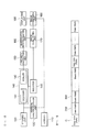
- FIG. 2 is a view schematically showing an OSD device according to an exemplary embodiment of the present invention.
- the OSD device may include a camera 110, a storing unit 120, a decoder 141, a line width calculating unit 150, an interpolation rate calculating unit 160, an image generating unit 170, an image combining unit 180, and a displaying unit 190.
- the camera 110 may be implemented by a general digital camera 110.
- the OSD device may further include a vertical synchronization unit 130 performing a vertical synchronization function (V sync) in order to naturally display an OSD image and an image photographed by the camera 110 in a finally output image.
- V sync vertical synchronization function
- the storing unit 120 may be implemented by various data storing devices. However, it is preferable that the storing unit 120 is implemented by a flash memory, or the like, having a relatively rapid data reading/writing speed in order to rapidly process data.
- the storing unit 120 may store the OSD image therein.
- the OSD image may be to display various kinds of information that may be visually provided to a driver at the time of driving of a vehicle, such as a driving guide line, a warning symbol, a warning message, an obstacle indication, and the like.
- an encoding process may be required.
- the OSD image may be stored in a bitmap format or be encoded and stored in other various formats.
- the OSD image is encoded in a format appropriate for the OSD device so as to be more efficiently and rapidly processed in a system.
- the OSD device may allow the OSD image to be encoded in an MRLC format including color information (C), a data width (DW), and a blank width (BW).
- C color information
- DW data width
- BW blank width
- FIG. 3 is a view schematically showing an MRLC format applied to the OSD device according to the exemplary embodiment of the present invention or an OSD method according to the exemplary embodiment of the present invention.
- the MRLC format is a format in which digital values defining the color information, the data width, and the blank width are continuously arranged.
- first data data generated by encoding the OSD image
- the first data may be stored in the storing unit 120 in advance and be read, decoded, and then used in the case in which it is required in a device.
- data generated by decoding the first data may be referred to as second data.
- This decoding process may be performed in a decoder 141 shown in FIG. 2 .
- the line width calculating unit 150 serves to calculate a line width of the OSD image from the second data.
- the line width calculating unit 150 may calculate the line width by easily extracting color information and a width of data having the corresponding color information from the second data.
- the OSD device performs interpolation for smoothly displaying the OSD image unlike the case according to the related art.
- the entire OSD image needs not to be interpolated, on which region in the OSD image and at which rate the interpolation is performed may be determined.
- a role of determining an interpolation target region and an interpolation rate as described above may be performed by the interpolation calculating unit 160.
- an applied line width may be the line width calculated in the line width calculating unit 150 described above.
- the line width calculated in the line width calculating unit 150 is LW
- a first coefficient is K1
- the width Y2 of the interpolation target region may be calculated by the following Equation 1.
- Y ⁇ 2 LW - LW / K ⁇ 1
- the first coefficient may be appropriately adjusted according to the line width and may be preferably determined to be in inverse proportion to the line width in a range between 1 and 2.
- each line width of 3 at both edges of a line having a line width of 12 may be determined to be the interpolation target region.
- an interpolation rate may be determined so that a color is gradually weakened toward a direction that becomes distant from a central portion of a corresponding line, which may be performed using a modified interpolation lookup table, or the like.
- the image generating unit 170 may serve to interpolate the OSD image according to the interpolation rate calculated in the interpolation rate calculating unit 160 to generate an OSD image to be output on an actual screen.
- the image combining unit 180 may serve to combine the image generated in the image generating unit 170 with the image photographed in the camera 110.
- the image combined in the image combining unit 180 may be output through the displaying unit 190 that may be implemented by various types of display devices such as a liquid crystal display (LCD), a light emitting diode (LED), a plasma display panel (PDP), and the like, to thereby be provided to the driver.
- LCD liquid crystal display
- LED light emitting diode
- PDP plasma display panel
- a size of the OSD image may be reduced in order to further reduce capacity of the first data.
- the OSD image having the reduced size and stored in the storing unit 120 needs to be enlarged.
- the OSD device may further include a scaler 142 provided between the decoder 141 and the line width calculating unit 150.
- the scaler 142 may increase or decrease a data width and a blank width in the second data at a predetermined rate to generate third data.
- a general register 145 is provided, such that the color information may be temporarily stored in the register 145 and then read in the image generating unit 170 to thereby be used in an image generating unit.
- the line width calculating unit 150 may calculate the line width of the OSD image according to the third data.
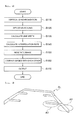
- FIG. 4 is a view schematically showing the OSD method according to the exemplary embodiment of the present invention.
- the OSD method may include a decoding step, a line width calculating step, an interpolation rate calculating step, an image generating step, an image combining step, and an outputting step.
- the first data generated by encoding an OSD image and stored in a separate storing unit are used.
- the first data may be data generated by encoding the OSD image in an MRLC format including color information, a data width, and a blank width.
- V sync vertical synchronization
- the first data are decoded to generate second data (S120).
- a line width of the OSD image is calculated from the second data (S130).
- the line width may be calculated by easily extracting color information and a width of data having the corresponding color information from the second data.
- the OSD image is interpolated according to the interpolation rate calculated in the interpolation rate calculating step to generate an OSD image to be output to an actual screen (S150).
- the image generated in an image generating unit is combined with an image photographed in a camera (S160).
- the image combined in the image combining step (S160) is output through a displaying unit that may be implemented by various types of display devices such as an LCD, an LED, a PDP, and the like, to thereby be provided to a driver (S170).
- a scaling process of increasing or decreasing a data width and a blank width in the second data at a predetermined rate to generate third data may be further performed.
- FIG. 5 is a view schematically showing an OSD image to which the OSD device according to the exemplary embodiment of the present invention or the OSD method according to the exemplary embodiment of the present invention is applied.
- the OSD image (GL) may be more smoothly and naturally displayed as compared to the OSD image shown in FIG. 1 .
- the OSD image is smoothly displayed to reduce the image shaking, thereby making it possible to provide an image smoother as compared to the case according to the related art.
- the present invention has been described in connection with what is presently considered to be practical exemplary embodiments. Although the exemplary embodiments of the present invention have been described, the present invention may be also used in various other combinations, modifications and environments. In other words, the present invention may be changed or modified within the range of concept of the invention disclosed in the specification, the range equivalent to the disclosure and/or the range of the technology or knowledge in the field to which the present invention pertains.
- the exemplary embodiments described above have been provided to explain the best state in carrying out the present invention. Therefore, they may be carried out in other states known to the field to which the present invention pertains in using other inventions such as the present invention and also be modified in various forms required in specific application fields and usages of the invention. Therefore, it is to be understood that the invention is not limited to the disclosed embodiments. It is to be understood that other embodiments are also included within the spirit and scope of the appended claims.
Landscapes
- Engineering & Computer Science (AREA)
- Multimedia (AREA)
- Signal Processing (AREA)
- Physics & Mathematics (AREA)
- Computer Hardware Design (AREA)
- General Physics & Mathematics (AREA)
- Theoretical Computer Science (AREA)
- Controls And Circuits For Display Device (AREA)
- Transforming Electric Information Into Light Information (AREA)
- Television Systems (AREA)
Applications Claiming Priority (1)
| Application Number | Priority Date | Filing Date | Title |
|---|---|---|---|
| KR1020120057541A KR101353090B1 (ko) | 2012-05-30 | 2012-05-30 | Osd 장치 및 osd 방법 |
Publications (2)
| Publication Number | Publication Date |
|---|---|
| EP2669887A2 true EP2669887A2 (fr) | 2013-12-04 |
| EP2669887A3 EP2669887A3 (fr) | 2017-05-03 |
Family
ID=48628582
Family Applications (1)
| Application Number | Title | Priority Date | Filing Date |
|---|---|---|---|
| EP13275119.9A Withdrawn EP2669887A3 (fr) | 2012-05-30 | 2013-05-16 | Dispositif et procédé d'affichage sur écran |
Country Status (3)
| Country | Link |
|---|---|
| US (1) | US20130321631A1 (fr) |
| EP (1) | EP2669887A3 (fr) |
| KR (1) | KR101353090B1 (fr) |
Citations (3)
| Publication number | Priority date | Publication date | Assignee | Title |
|---|---|---|---|---|
| KR20100006845A (ko) | 2008-07-10 | 2010-01-22 | 삼성전자주식회사 | Osd 아이템 표시방법 및 이를 적용한 디스플레이 장치 |
| KR20100038981A (ko) | 2008-10-07 | 2010-04-15 | 삼성테크윈 주식회사 | 카메라로 촬영된 영상에서의 osd 표시 제어방법 및 장치, 모니터에서의 osd 표시 제어방법 및 장치 |
| KR20100129965A (ko) | 2009-06-02 | 2010-12-10 | 삼성전기주식회사 | 자동차용 카메라 모듈 및 이를 이용한 주차 안내선 표시방법 |
Family Cites Families (10)
| Publication number | Priority date | Publication date | Assignee | Title |
|---|---|---|---|---|
| US20010033734A1 (en) * | 1989-05-02 | 2001-10-25 | Minolta Co., Ltd., | Image information processing system |
| DE69028038T2 (de) * | 1989-05-17 | 1997-01-30 | Minolta Camera Kk | Aufnahme- und Reprokamera |
| KR920006067B1 (ko) * | 1989-11-02 | 1992-07-27 | 삼성전자 주식회사 | 온스크린 디스플레이장치에 있어서 문자 보간회로 |
| JP4880172B2 (ja) * | 2000-04-21 | 2012-02-22 | パナソニック株式会社 | 画像処理方法及び画像処理装置 |
| TW591515B (en) * | 2003-08-04 | 2004-06-11 | Ali Corp | Method to display double byte character set by OSD and the decoding/playing/duplication system to update the display frame using the method |
| JP4933209B2 (ja) * | 2006-10-05 | 2012-05-16 | パナソニック株式会社 | 映像処理装置 |
| AU2007254661A1 (en) * | 2007-12-24 | 2009-07-09 | Canon Kabushiki Kaisha | Printing and authentication of a security document on a substrate |
| JP4687725B2 (ja) * | 2008-02-12 | 2011-05-25 | ソニー株式会社 | 画像処理装置及び画像処理方法、並びにコンピュータ・プログラム |
| KR101010186B1 (ko) | 2010-05-20 | 2011-02-15 | 주식회사 아이티마니아 | 후방주차가이드를 위한 가이드라인 오에스디표시시스템 및 그 제어방법 |
| JP5871485B2 (ja) * | 2011-05-17 | 2016-03-01 | キヤノン株式会社 | 画像送信装置、画像送信方法、及びプログラム |
-
2012
- 2012-05-30 KR KR1020120057541A patent/KR101353090B1/ko not_active Expired - Fee Related
-
2013
- 2013-05-16 EP EP13275119.9A patent/EP2669887A3/fr not_active Withdrawn
- 2013-05-29 US US13/905,071 patent/US20130321631A1/en not_active Abandoned
Patent Citations (3)
| Publication number | Priority date | Publication date | Assignee | Title |
|---|---|---|---|---|
| KR20100006845A (ko) | 2008-07-10 | 2010-01-22 | 삼성전자주식회사 | Osd 아이템 표시방법 및 이를 적용한 디스플레이 장치 |
| KR20100038981A (ko) | 2008-10-07 | 2010-04-15 | 삼성테크윈 주식회사 | 카메라로 촬영된 영상에서의 osd 표시 제어방법 및 장치, 모니터에서의 osd 표시 제어방법 및 장치 |
| KR20100129965A (ko) | 2009-06-02 | 2010-12-10 | 삼성전기주식회사 | 자동차용 카메라 모듈 및 이를 이용한 주차 안내선 표시방법 |
Also Published As
| Publication number | Publication date |
|---|---|
| KR20130134198A (ko) | 2013-12-10 |
| US20130321631A1 (en) | 2013-12-05 |
| EP2669887A3 (fr) | 2017-05-03 |
| KR101353090B1 (ko) | 2014-01-20 |
Similar Documents
| Publication | Publication Date | Title |
|---|---|---|
| US8675738B2 (en) | Video decoding method without using additional buffers for storing scaled frames and system thereof | |
| US8384738B2 (en) | Compositing windowing system | |
| US8791986B2 (en) | Display apparatus and control method thereof | |
| US20110228057A1 (en) | Image Processing Apparatus, Image Conversion Method, and Program | |
| US12277915B2 (en) | Video timing for display systems with variable refresh rates | |
| EP2479985A1 (fr) | Dispositif d'affichage vidéo | |
| KR20150126221A (ko) | 적응적 영상 데이터 압축 방법 및 장치 | |
| JP2005109568A (ja) | 映像表示装置及びプログラム | |
| US20220270539A1 (en) | Display driver integrated circuit, image processor, and operation method thereof | |
| CN103098118A (zh) | 描绘装置及方法 | |
| CN101405788B (zh) | 显示面板驱动装置、显示面板的驱动方法、显示装置、电视接收机 | |
| CN102918830A (zh) | 图像处理装置和方法、图像显示装置和方法 | |
| KR20170093505A (ko) | 영상 처리 방법, 장치 및 기록 매체 | |
| US6879329B2 (en) | Image processing apparatus having processing operation by coordinate calculation | |
| EP2669887A2 (fr) | Dispositif et procédé d'affichage sur écran | |
| US8249395B2 (en) | System, method, and computer program product for picture resizing | |
| US20130235061A1 (en) | Video processing apparatus and system for correcting video signal | |
| US8345055B2 (en) | Image display device | |
| US20100328350A1 (en) | Bifocal display device and bifocal display method | |
| KR20080076053A (ko) | Osd 크기 변환 장치 | |
| US20140118394A1 (en) | Image processing method and associated apparatus | |
| JP4741916B2 (ja) | 画像処理装置、画像処理方法及び該方法を実行するための画像処理プログラムを格納したコンピュータ読み取り可能な記録媒体 | |
| JP3863887B2 (ja) | ディスプレイ駆動装置 | |
| US20170278463A1 (en) | Display system, display control device, display control method, and program | |
| JP2010128292A (ja) | 画像表示システム |
Legal Events
| Date | Code | Title | Description |
|---|---|---|---|
| PUAI | Public reference made under article 153(3) epc to a published international application that has entered the european phase |
Free format text: ORIGINAL CODE: 0009012 |
|
| 17P | Request for examination filed |
Effective date: 20130516 |
|
| AK | Designated contracting states |
Kind code of ref document: A2 Designated state(s): AL AT BE BG CH CY CZ DE DK EE ES FI FR GB GR HR HU IE IS IT LI LT LU LV MC MK MT NL NO PL PT RO RS SE SI SK SM TR |
|
| AX | Request for extension of the european patent |
Extension state: BA ME |
|
| PUAL | Search report despatched |
Free format text: ORIGINAL CODE: 0009013 |
|
| AK | Designated contracting states |
Kind code of ref document: A3 Designated state(s): AL AT BE BG CH CY CZ DE DK EE ES FI FR GB GR HR HU IE IS IT LI LT LU LV MC MK MT NL NO PL PT RO RS SE SI SK SM TR |
|
| AX | Request for extension of the european patent |
Extension state: BA ME |
|
| RIC1 | Information provided on ipc code assigned before grant |
Ipc: G09G 5/00 20060101AFI20170329BHEP |
|
| STAA | Information on the status of an ep patent application or granted ep patent |
Free format text: STATUS: REQUEST FOR EXAMINATION WAS MADE |
|
| STAA | Information on the status of an ep patent application or granted ep patent |
Free format text: STATUS: THE APPLICATION IS DEEMED TO BE WITHDRAWN |
|
| 18D | Application deemed to be withdrawn |
Effective date: 20171104 |