EP2669417A1 - Washer-dryer machine with a heat pump - Google Patents
Washer-dryer machine with a heat pump Download PDFInfo
- Publication number
- EP2669417A1 EP2669417A1 EP12169807.0A EP12169807A EP2669417A1 EP 2669417 A1 EP2669417 A1 EP 2669417A1 EP 12169807 A EP12169807 A EP 12169807A EP 2669417 A1 EP2669417 A1 EP 2669417A1
- Authority
- EP
- European Patent Office
- Prior art keywords
- washer
- evaporator
- dryer machine
- filter
- air duct
- Prior art date
- Legal status (The legal status is an assumption and is not a legal conclusion. Google has not performed a legal analysis and makes no representation as to the accuracy of the status listed.)
- Withdrawn
Links
- 238000005406 washing Methods 0.000 claims abstract description 68
- 239000007788 liquid Substances 0.000 claims abstract description 67
- 238000001035 drying Methods 0.000 claims abstract description 38
- 239000012530 fluid Substances 0.000 claims abstract description 11
- 238000001816 cooling Methods 0.000 claims abstract description 6
- 238000010438 heat treatment Methods 0.000 claims abstract description 6
- 238000004891 communication Methods 0.000 claims abstract description 4
- 238000004140 cleaning Methods 0.000 claims description 25
- 230000008878 coupling Effects 0.000 claims description 18
- 238000010168 coupling process Methods 0.000 claims description 18
- 238000005859 coupling reaction Methods 0.000 claims description 18
- 238000012423 maintenance Methods 0.000 claims description 7
- 238000000034 method Methods 0.000 description 12
- XLYOFNOQVPJJNP-UHFFFAOYSA-N water Substances O XLYOFNOQVPJJNP-UHFFFAOYSA-N 0.000 description 9
- 230000003213 activating effect Effects 0.000 description 2
- 239000003599 detergent Substances 0.000 description 2
- 238000005516 engineering process Methods 0.000 description 2
- 238000011144 upstream manufacturing Methods 0.000 description 2
- 238000009833 condensation Methods 0.000 description 1
- 230000005494 condensation Effects 0.000 description 1
- 238000007667 floating Methods 0.000 description 1
- 230000004907 flux Effects 0.000 description 1
- 230000005484 gravity Effects 0.000 description 1
- 238000003475 lamination Methods 0.000 description 1
- 238000010412 laundry washing Methods 0.000 description 1
- 239000002245 particle Substances 0.000 description 1
- 239000008399 tap water Substances 0.000 description 1
- 235000020679 tap water Nutrition 0.000 description 1
- 230000000007 visual effect Effects 0.000 description 1
Images


Classifications
-
- D—TEXTILES; PAPER
- D06—TREATMENT OF TEXTILES OR THE LIKE; LAUNDERING; FLEXIBLE MATERIALS NOT OTHERWISE PROVIDED FOR
- D06F—LAUNDERING, DRYING, IRONING, PRESSING OR FOLDING TEXTILE ARTICLES
- D06F25/00—Washing machines with receptacles, e.g. perforated, having a rotary movement, e.g. oscillatory movement, the receptacle serving both for washing and for centrifugally separating water from the laundry and having further drying means, e.g. using hot air
-
- D—TEXTILES; PAPER
- D06—TREATMENT OF TEXTILES OR THE LIKE; LAUNDERING; FLEXIBLE MATERIALS NOT OTHERWISE PROVIDED FOR
- D06F—LAUNDERING, DRYING, IRONING, PRESSING OR FOLDING TEXTILE ARTICLES
- D06F58/00—Domestic laundry dryers
- D06F58/20—General details of domestic laundry dryers
- D06F58/206—Heat pump arrangements
-
- D—TEXTILES; PAPER
- D06—TREATMENT OF TEXTILES OR THE LIKE; LAUNDERING; FLEXIBLE MATERIALS NOT OTHERWISE PROVIDED FOR
- D06F—LAUNDERING, DRYING, IRONING, PRESSING OR FOLDING TEXTILE ARTICLES
- D06F2103/00—Parameters monitored or detected for the control of domestic laundry washing machines, washer-dryers or laundry dryers
- D06F2103/18—Washing liquid level
-
- D—TEXTILES; PAPER
- D06—TREATMENT OF TEXTILES OR THE LIKE; LAUNDERING; FLEXIBLE MATERIALS NOT OTHERWISE PROVIDED FOR
- D06F—LAUNDERING, DRYING, IRONING, PRESSING OR FOLDING TEXTILE ARTICLES
- D06F2105/00—Systems or parameters controlled or affected by the control systems of washing machines, washer-dryers or laundry dryers
- D06F2105/08—Draining of washing liquids
-
- D—TEXTILES; PAPER
- D06—TREATMENT OF TEXTILES OR THE LIKE; LAUNDERING; FLEXIBLE MATERIALS NOT OTHERWISE PROVIDED FOR
- D06F—LAUNDERING, DRYING, IRONING, PRESSING OR FOLDING TEXTILE ARTICLES
- D06F2105/00—Systems or parameters controlled or affected by the control systems of washing machines, washer-dryers or laundry dryers
- D06F2105/58—Indications or alarms to the control system or to the user
-
- D—TEXTILES; PAPER
- D06—TREATMENT OF TEXTILES OR THE LIKE; LAUNDERING; FLEXIBLE MATERIALS NOT OTHERWISE PROVIDED FOR
- D06F—LAUNDERING, DRYING, IRONING, PRESSING OR FOLDING TEXTILE ARTICLES
- D06F34/00—Details of control systems for washing machines, washer-dryers or laundry dryers
- D06F34/14—Arrangements for detecting or measuring specific parameters
-
- D—TEXTILES; PAPER
- D06—TREATMENT OF TEXTILES OR THE LIKE; LAUNDERING; FLEXIBLE MATERIALS NOT OTHERWISE PROVIDED FOR
- D06F—LAUNDERING, DRYING, IRONING, PRESSING OR FOLDING TEXTILE ARTICLES
- D06F58/00—Domestic laundry dryers
- D06F58/20—General details of domestic laundry dryers
- D06F58/22—Lint collecting arrangements
Definitions
- the present invention relates to a washer-dryer machine comprising a heat pump for realising a drying function.
- Washer-dryer machines combine a laundry washing machine and a laundry drying machine in one appliance having the size of a stand-alone washing machine.
- washer-dryer machines using heat pump technology for dehumidifying the process air
- these known washer-dryer machines comprise a heat pump provided with an evaporator, arranged in the air duct for cooling and dehumidifying hot air exiting a laundry treatment chamber, and with a condenser, arranged in the same air duct, downstream of the evaporator, for heating air before admitting it into the laundry treatment chamber.
- a drawback of these known washer-dryer machines is that lint/fluff removed from the laundry by the process air can settle on the evaporator, reducing its heat-exchanging surface, and therefore its performances. There is also the risk that lint/fluff settled on the evaporator could catch fire due to the high temperature of the air flux exiting the laundry treatment chamber and passing through the evaporator.
- some known washer-dryer machines using heat pump technology are provided with a lint/fluff filter placed in the air duct, upstream of the evaporator, in order to catch lint/fluff carried by process air, so as to try to avoid that this lint/fluff can reach the evaporator.
- lint/fluff in particular small fibres and particles, may cross the filter without being trapped, in which case this lint/fluff may settle on the evaporator, with the above mentioned risks.
- a washer-dryer machine comprising a heat pump for treating (i.e. heating and also cooling and dehumidifying) process air, in which the evaporator of the heat pump is arranged in such a way that during a washing cycle the washing liquid present in the machine at least partially submerges the evaporator, so as to at least partially wash the latter and at least partially remove fluff/lint from this evaporator, the latter is kept free/clean from lint/fluff, without requiring a manual cleaning performed by the user.
- a washer-dryer machine comprising:
- the evaporator is arranged in such a way that during a washing cycle the washing liquid present inside the tub and/or inside the air duct and/or draining channel at least partially submerges the evaporator, so as to at least partially wash the latter and at least partially remove fluff/lint from the evaporator.
- the washing liquid reaches the evaporator and cleans it from the lint or fluff. A very comfortable, easy and secure cleaning of the evaporator is therefore possible.
- the evaporator is arranged in such a way that during a drying cycle the liquid optionally present inside the tub and/or inside the air duct and/or the draining channel does not submerge the evaporator.
- the evaporator can carry out its function properly.
- the process air passes the evaporator, where liquid contained in process air condenses.
- the condensed liquid drops back into the draining channel.
- the washer-dryer machine comprises a lint/fluff filter arranged in such a way to trap fluff or lint exiting the laundry treatment chamber and moving towards the evaporator through the air duct, wherein the filter is arranged in such a way that during a washing cycle the washing liquid present inside the tub and/or inside the air duct and/or the draining channel at least partially submerges the filter, so as to at least partially wash the latter and at least partially remove fluff/lint from the filter.
- the liquid level reaches the filter and covers it, washing away and cleaning the filter from lint or fluff which was collected there during the drying mode.
- the fluff or lint is transported away. In this way, the filter is cleaned after each washing cycle.
- the filter is arranged in such a way that during a drying cycle the liquid optionally present inside the tub and/or inside the air duct and/or the draining channel does not submerge the filter.
- the filter carries out its function without being impeded or covered by the washing liquid.
- the washer-dryer machine comprises a level sensor, connected to a control device of the washer-dryer machine, for detecting the liquid level inside the draining channel and/or inside the air duct.
- control device is configured in such a way that, if, during a drying cycle, the liquid level inside the draining channel and/or inside the air duct reaches a prefixed threshold value, the control device activates the draining pump for draining at least part of the liquid present inside the draining channel.
- the laundry treatment chamber is connected to the draining channel via a first coupling joint, the draining channel and the coupling joint being arranged in such a way that, once a liquid has entered the draining channel and has at least partially filled the first coupling joint, the latter can't be fully emptied by operating the draining pump, so that liquid present in the coupling joint impedes air contained in the laundry treatment chamber from reaching the draining channel via the first coupling joint.
- the washer-dryer machine comprises also an auxiliary cleaning system adapted for washing one or more components (e.g. the evaporator and/or, if provided, the filter) of the washer-dryer machine.
- an auxiliary cleaning system adapted for washing one or more components (e.g. the evaporator and/or, if provided, the filter) of the washer-dryer machine.
- auxiliary cleaning system may advantageously comprise an auxiliary duct coupled in fluid connection with a first nozzle arranged such that a jet of liquid sprayed from the first nozzle cleans the evaporator.
- the auxiliary cleaning system may advantageously comprise an auxiliary duct coupled in fluid connection with a second nozzle arranged such that a jet of liquid sprayed from the second nozzle cleans the filter.
- Providing an auxiliary cleaning system allows cleaning the evaporator and/or, if provided, the filter, independently from performing the washing cycle.
- the cleaning procedure can be carried out at each desired time, when it is necessary. Further the cleaning procedure can be carried out using tap water.
- control device of the washer-dryer machine is configured for providing an alarm signal to inform a user about the necessity to clean the filter after the washer-dryer machine has performed a prefixed number of consecutive drying cycles.
- control device is configured for automatically loading a washing liquid inside the tub, so as to at least partially submerge the evaporator and at least partially wash the latter in such a way to at least partially remove fluff/lint from the evaporator, after the washer-dryer machine has performed a prefixed number of consecutive drying cycles.
- the control device is configured for automatically loading a washing liquid inside the tub, so as to at least partially submerge the filter and at least partially wash the latter in such a way to at least partially remove fluff/lint from the filter, after the washer-dryer machine has performed a prefixed number of consecutive drying cycles.
- the drum comprises, on its lateral surface, an opening arranged in such a way that it can face the filter when the drum is in a prefixed angular position, wherein the opening allows accessing the filter for its manual maintenance, and wherein the opening is closed by a removable closure device.
- the filter can be reached manually for being cleaned manually or for being detached from its seat in the air inlet channel. Easy and comfortable access is provided to the filter in this way.
- the removable closure device may advantageously be a lifter adapted to engage the laundry during the rotation of the drum, which can be pivoted with respect to the drum for providing access to the opening.
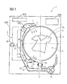
- FIG 1 illustrates a schematic drawing of a washer-dryer machine according to the invention, during a drying cycle.
- a washer-dryer machine shall be understood as a washing machine with drying function.
- Washer-dryer machine 1 comprises a casing 101 enclosing a washing tub 2 (called also simply tub), defining a laundry treatment chamber 4 containing a rotatable drum 3 wherein the laundry 25 to be washed and dried is placed.
- the drum 3 rotates during operation of a washing and/or drying cycles of the washer-dryer machine 1 and, thus, the laundry 25 placed within the drum 3 is rotated or tumbled, respectively.
- the washer-dryer machine 1 comprises an air duct 16 (which may be a single duct or may comprise a plurality of ducts fluidly connected one another) for circulating hot air in the laundry treatment chamber 4, and in particular inside the drum 3, and comprises also a heat pump 5 comprising an evaporator 6, arranged in the air duct 16 for cooling and dehumidifying hot air exiting the laundry treatment chamber 4, and a condenser 102, arranged in the air duct 16, downstream of the evaporator 6, for heating air before admitting it into the laundry treatment chamber 4.
- a heat pump 5 comprising an evaporator 6, arranged in the air duct 16 for cooling and dehumidifying hot air exiting the laundry treatment chamber 4, and a condenser 102, arranged in the air duct 16, downstream of the evaporator 6, for heating air before admitting it into the laundry treatment chamber 4.
- Heat pump 5 also preferably comprises a compressor 26 and a lamination valve 27 which are commonly known and will not be described in detail.
- the air duct 16 is fluidly connected to the tub 2, and therefore to the laundry treatment chamber 4, by an air inlet 17 and an air outlet 8, through which air respectively enters and exits the tub 2.
- a fan 7 is arranged in the air duct 16 for creating an air flow that passes through the evaporator 6, then through the condenser 102, then enters the tub 2 via the air inlet 17 (so as to contact the laundry 25 contained in the drum 3 and removing the moisture from such laundry 25), and exits the tub 2 via the air outlet 8.
- a lint/fluff filter 9 is provided at the air outlet 8 for trapping fluff or lint exiting the laundry treatment chamber 4 and moving towards evaporator 6; filter 9 may have also a different position in the air duct 16, provided that it is placed upstream the evaporator 16, i.e. in a position in which air exiting laundry treatment chamber 4 passes through the filter 9 before contacting the evaporator 6.
- Washer-dryer machine 1 comprises also a washing liquid inlet circuit, not illustrated, adapted to bring a washing liquid (i.e. water or water mixed with a washing/rinsing product, for example a detergent or a laundry softener) into the tub 2.
- Washing liquid inlet circuit may advantageously comprise a series of ducts connectable to the water mains, valves, a detergent drawer, etc.
- the washer-dryer machine comprises also a draining channel 11, fluidly connected to the laundry treatment chamber 4, i.e. to the tub 2, and comprising a draining pump 15, for draining washing liquid from the laundry treatment chamber 4.
- the draining channel 11 is fluidly connected to the tub 2 via a coupling joint 13, preferably comprising a flexible or rigid conduit.
- the coupling joint 13 is preferably coupled to the tub 2 at the lowermost position of the tub 2 or the tub shell adjacent to a sump 24 advantageously formed in the tub 2.
- liquid which is collected in the lowermost position of the tub 2 or in the sump 24 (if provided) flows through the coupling joint 13 into the draining channel 11.
- the draining channel 11 and the air duct 16 are in fluid communication one another, in such a way that moisture condensed in the evaporator 6 during the drying cycle goes in the draining channel 11 and can be drained away via the latter.
- washer-dryer machine 1 comprises also a level sensor 10 (for example a floating level sensor), connected to a control device of the washer-dryer machine 1, schematically represented in enclosed figures and numbered 103 (connection is not represented in enclosed figures), adapted for detecting the liquid level inside the draining channel 11 and/or inside the air duct 16 (which, being fluidly connected to the draining channel 11, can be partially filled with washing liquid and/or condensed liquid).
- level sensor 10 is arranged in a conduit 12 connecting the draining channel 11 to the aid duct 16.
- the control device 103 is configured in such a way that, if, during a drying cycle, the liquid level detected by the level sensor 10 is higher than a prefixed threshold value (which may be memorized in the control device 103), the control device 103 activates the draining pump 15 for draining at least part of the liquid present inside the draining channel 11.
- a prefixed threshold value which may be memorized in the control device 103
- the control device 103 activates the draining pump 15 for draining at least part of the liquid present inside the draining channel 11.
- a prefixed threshold value which may be memorized in the control device 103
- the moisture or humidity that is absorbed or dissolved in the process air condenses and regains a liquid state.
- the moisture or humidity that has become fluid now drops down into the draining channel 11 via the conduit 12.
- the process air passes the air duct 16 in the direction of the air flow AF and is redirected to the air outlet 17 again.
- the passage which is formed by the coupling joint 13 serves as a sort of siphon for avoiding that during a drying cycle a part of the process air can be drained outside the machine via the draining channel 11.
- this is obtained by positioning at least part of the pump 15 at a level at least slightly higher than the outlet region (i.e. the region connected to the draining channel 11).
- FIG 2 schematically illustrates the washer-dryer machine 1 during a washing cycle.
- Evaporator 6 is arranged in such a way that during a washing cycle the washing liquid (water or water mixed with washing/rinsing products) present inside the tub 2 and/or inside the duct 16 and/or the draining channel 11 at least partially submerges the evaporator 6, so as to at least partially wash the latter and at least partially remove fluff/lint from this evaporator 6.
- the washing liquid water or water mixed with washing/rinsing products
- the evaporator 6 is arranged in such a way that during a drying cycle the liquid optionally present inside the tub 2 and/or inside the air duct 16 and/or the draining channel 11 does not submerge the evaporator 6, so as to allow the whole surface of the evaporator 6 to be exposed to process air.
- a lint/fluff filter 9 is provided, it is arranged in such a way that during a washing cycle the washing liquid present inside the tub 2 and/or inside the air duct 16 and/or the draining channel 11 at least partially submerges the filter 9, so as to at least partially wash the latter and at least partially remove fluff/lint from the filter 9.
- the filter 9 is arranged in such a way that during a drying cycle the liquid optionally present inside the tub 2 and/or inside the air duct 16 and/or the draining channel 11 does not submerge the filter 9.
- the fluff or lint removed by the washing liquid is transported into the draining channel 11 and from there it is drained outside the washer-dryer machine 1.
- the fan 7 does not rotate and thus does not convey or ventilate air in the air duct 16.
- control device 103 is configured in such a way that it controls the introduction of washing liquid into the tub 2 (by controlling the washing liquid inlet circuit), so that heat exchanger 6 (and, if provided, preferably also filter 9) is cleaned at the beginning of a washing cycle or during some phases of a drying cycles.
- control device 103 is configured for providing an alarm signal (for example a sound and/or a visual message displayed via the user interface 104 of the machine, etc.) to inform a user about the necessity to clean the filter 9 after the washer-dryer machine 1 has performed a prefixed number of consecutive (i.e. not spaced out by a washing cycle, in which washing liquid would have washed the evaporator 6 and the filter 9) drying cycles.
- an alarm signal for example a sound and/or a visual message displayed via the user interface 104 of the machine, etc.
- control device 103 is configured for automatically loading washing liquid inside the tub 2 (e.g. by controlling the washing liquid inlet circuit), so as to at least partially submerge the evaporator 6 (and preferably, if provided, also the filter 9) and at least partially wash the latter (and preferably, if provided, also the filter 9) in such a way to at least partially remove fluff/lint from the evaporator 6 (and preferably, if provided, also the filter 9), after the washer-dryer machine 1 has performed a prefixed number of consecutive (i.e. not spaced out by a washing cycle, in which washing liquid would have washed the evaporator 6 and the filter 9) drying cycles.
- FIG 3 schematically illustrates a further embodiment of a washer-dryer machine 1 according to the invention during a manual maintenance phase.
- the drum 3 comprises, on its lateral surface 3a, an opening 105 arranged in such a way that it can face the filter 9 when the drum 3 is in a prefixed angular position; in this position, therefore, opening 105 allows accessing filter 9 for its manual maintenance (filter 9 may be removable or not).
- Opening 105 may be closed by a removable closure device.
- Advantageously removable closure device comprises a lifter 18 adapted to engage the laundry during the rotation of the drum 3, which can be pivoted with respect to the drum 3 for providing access to opening 105.
- Lifter 18 is placed on the interior side of the lateral surface 3a of the drum 3.
- Lifters 18 take and lift the laundry 25 in the washing process and/or drying process when the drum 3 rotates, so that the laundry 25 is moved during the washing process.
- the lifter 18 can be pivoted and a user can manually reach the filter 9.
- the filter 9 can preferably be provided detachably, such that the user can take it out and clean it from fluff or lint and re-install it.
- FIG 4 schematically illustrates a further embodiment of a washer-dryer machine 1 according to the invention, having an auxiliary cleaning system 19 adapted for washing one or more components (for example the evaporator 6 and/or, if provided, preferably also the filter 9), of the washer-dryer machine 1.
- auxiliary cleaning system 19 adapted for washing one or more components (for example the evaporator 6 and/or, if provided, preferably also the filter 9), of the washer-dryer machine 1.
- the auxiliary cleaning system 19 comprises an auxiliary pump 20 which can supply the cleaning system 19 with water or washing liquid.
- the auxiliary cleaning system 19 can be connected to the water supplying mains via an electro-valve, not illustrated; in this case the auxiliary pump can be not provided.
- the auxiliary cleaning system 19 may comprise an auxiliary duct 21 coupled in fluid connection with a first nozzle 22 arranged such that a jet of liquid sprayed from this first nozzle 22 cleans the evaporator 6.
- the first nozzle 22 is oriented in a direction in which a jet sprayed from the first nozzle 22 touches the condensing surfaces of the evaporator 6 and removes lint or fluff which is collected therein.
- the auxiliary cleaning system 19 may comprise a second nozzle 23, preferably coupled in fluid connection with the auxiliary duct 21 (or with a further auxiliary duct, not illustrated), arranged such that a jet of liquid sprayed from this second nozzle 23 cleans the filter 9.
- the second nozzle 23 is advantageously arranged adjacent to the filter 9 and oriented in a direction parallel to the interior surface of the filter 9.
- a jet sprayed from the nozzle 22 rinses or cleans the interior surface of the filter 9 from fluff or lint.
- the auxiliary cleaning system 19 can be activated by means of the control device 103 at the beginning of a washing cycle or during some phases of drying cycles. It is also possible that a user activates the auxiliary cleaning system 19 manually.
- control device 103 is configured for automatically activating the auxiliary cleaning system 19 (for example by activating the auxiliary pump 20, if provided, or by opening the electro-valve connecting the auxiliary duct 21 to the water supply means), after the washer-dryer machine 1 has performed a prefixed number of consecutive (i.e. not spaced out by a washing cycle, in which washing liquid would have washed the evaporator 6 and the filter 9) drying cycles.
Landscapes
- Engineering & Computer Science (AREA)
- Textile Engineering (AREA)
- Detail Structures Of Washing Machines And Dryers (AREA)
Abstract
Description
- The present invention relates to a washer-dryer machine comprising a heat pump for realising a drying function.
- Washer-dryer machines combine a laundry washing machine and a laundry drying machine in one appliance having the size of a stand-alone washing machine.
- There are known washer-dryer machines using heat pump technology for dehumidifying the process air; these known washer-dryer machines comprise a heat pump provided with an evaporator, arranged in the air duct for cooling and dehumidifying hot air exiting a laundry treatment chamber, and with a condenser, arranged in the same air duct, downstream of the evaporator, for heating air before admitting it into the laundry treatment chamber.
- A drawback of these known washer-dryer machines is that lint/fluff removed from the laundry by the process air can settle on the evaporator, reducing its heat-exchanging surface, and therefore its performances. There is also the risk that lint/fluff settled on the evaporator could catch fire due to the high temperature of the air flux exiting the laundry treatment chamber and passing through the evaporator.
- In order to try to reduce this drawback, some known washer-dryer machines using heat pump technology are provided with a lint/fluff filter placed in the air duct, upstream of the evaporator, in order to catch lint/fluff carried by process air, so as to try to avoid that this lint/fluff can reach the evaporator.
- However some lint/fluff, in particular small fibres and particles, may cross the filter without being trapped, in which case this lint/fluff may settle on the evaporator, with the above mentioned risks.
- In these known washer-dryer machines there is therefore the need of periodically cleaning the evaporator, and also, if provided, the lint/fluff filter; however this may be not easy, since typically the evaporator is positioned inside the air duct, in a position in which it is not or at least not-easily accessible by a user. Also the filter, if provided, is typically not easily accessible, and therefore its maintenance is not very comfortable.
- It is the aim of the present invention to provide a washer-dryer machine using a heat pump system with ensures that the evaporator of the heat pump is kept clean from lint/fluff.
- It is a further object of the present invention to allow keeping the lint/fluff filter (if provided) clean from lint/fluff.
- It is a still further object of the present invention to provide additional comfort and easy maintenance for a user of the washer-dryer machine.
- It is a further object of the present invention to provide easy access to the lint/fluff filter (if provided).
- The aim and objects of the present invention are achieved by a washer-dryer machine according to the invention.
- In particular applicant has found that by providing a washer-dryer machine comprising a heat pump for treating (i.e. heating and also cooling and dehumidifying) process air, in which the evaporator of the heat pump is arranged in such a way that during a washing cycle the washing liquid present in the machine at least partially submerges the evaporator, so as to at least partially wash the latter and at least partially remove fluff/lint from this evaporator, the latter is kept free/clean from lint/fluff, without requiring a manual cleaning performed by the user.
- The above aim and objects are achieved by a washer-dryer machine comprising:
- a tub forming a laundry treatment chamber and containing a rotatable drum wherein laundry can be loaded and submitted to a washing cycle and/or to a drying cycle;
- an air duct, for circulating hot air in the laundry treatment chamber;
- a heat pump comprising an evaporator, arranged in the air duct for cooling and dehumidifying hot air exiting the laundry treatment chamber, and a condenser, arranged in the air duct, downstream of said evaporator, for heating air before admitting it into the laundry treatment chamber;
- a draining channel, fluidly connected to the laundry treatment chamber and comprising a draining pump, for draining washing liquid from the laundry treatment chamber;
- The evaporator is arranged in such a way that during a washing cycle the washing liquid present inside the tub and/or inside the air duct and/or draining channel at least partially submerges the evaporator, so as to at least partially wash the latter and at least partially remove fluff/lint from the evaporator.
- Therefore during the washing cycle, the washing liquid reaches the evaporator and cleans it from the lint or fluff. A very comfortable, easy and secure cleaning of the evaporator is therefore possible.
- Advantageously, the evaporator is arranged in such a way that during a drying cycle the liquid optionally present inside the tub and/or inside the air duct and/or the draining channel does not submerge the evaporator.
- Thus, in the drying cycle, the evaporator can carry out its function properly. The process air passes the evaporator, where liquid contained in process air condenses. The condensed liquid drops back into the draining channel.
- Preferably, the washer-dryer machine comprises a lint/fluff filter arranged in such a way to trap fluff or lint exiting the laundry treatment chamber and moving towards the evaporator through the air duct, wherein the filter is arranged in such a way that during a washing cycle the washing liquid present inside the tub and/or inside the air duct and/or the draining channel at least partially submerges the filter, so as to at least partially wash the latter and at least partially remove fluff/lint from the filter. During the washing cycle, therefore, the liquid level reaches the filter and covers it, washing away and cleaning the filter from lint or fluff which was collected there during the drying mode. When the washing liquid is drained, the fluff or lint is transported away. In this way, the filter is cleaned after each washing cycle.
- Preferably, the filter is arranged in such a way that during a drying cycle the liquid optionally present inside the tub and/or inside the air duct and/or the draining channel does not submerge the filter.
- During the drying cycle, therefore, the filter carries out its function without being impeded or covered by the washing liquid.
- In an advantageous embodiment, the washer-dryer machine comprises a level sensor, connected to a control device of the washer-dryer machine, for detecting the liquid level inside the draining channel and/or inside the air duct.
- Preferably, the control device is configured in such a way that, if, during a drying cycle, the liquid level inside the draining channel and/or inside the air duct reaches a prefixed threshold value, the control device activates the draining pump for draining at least part of the liquid present inside the draining channel.
- In an advantageous embodiment, the laundry treatment chamber is connected to the draining channel via a first coupling joint, the draining channel and the coupling joint being arranged in such a way that, once a liquid has entered the draining channel and has at least partially filled the first coupling joint, the latter can't be fully emptied by operating the draining pump, so that liquid present in the coupling joint impedes air contained in the laundry treatment chamber from reaching the draining channel via the first coupling joint.
- In a preferred embodiment the washer-dryer machine comprises also an auxiliary cleaning system adapted for washing one or more components (e.g. the evaporator and/or, if provided, the filter) of the washer-dryer machine.
- In this case the auxiliary cleaning system may advantageously comprise an auxiliary duct coupled in fluid connection with a first nozzle arranged such that a jet of liquid sprayed from the first nozzle cleans the evaporator.
- If the washer-dryer machine comprises a lint/fluff filter, the auxiliary cleaning system may advantageously comprise an auxiliary duct coupled in fluid connection with a second nozzle arranged such that a jet of liquid sprayed from the second nozzle cleans the filter.
- Providing an auxiliary cleaning system allows cleaning the evaporator and/or, if provided, the filter, independently from performing the washing cycle. The cleaning procedure can be carried out at each desired time, when it is necessary. Further the cleaning procedure can be carried out using tap water.
- In an advantageous embodiment, the control device of the washer-dryer machine is configured for providing an alarm signal to inform a user about the necessity to clean the filter after the washer-dryer machine has performed a prefixed number of consecutive drying cycles.
- Thus, additional comfort is achieved. The user is informed automatically about the status of the machine.
- In a further advantageous embodiment, the control device is configured for automatically loading a washing liquid inside the tub, so as to at least partially submerge the evaporator and at least partially wash the latter in such a way to at least partially remove fluff/lint from the evaporator, after the washer-dryer machine has performed a prefixed number of consecutive drying cycles.
- In a further advantageous embodiment, in which the washer-dryer machine is provided with a lint/fluff filter, the control device is configured for automatically loading a washing liquid inside the tub, so as to at least partially submerge the filter and at least partially wash the latter in such a way to at least partially remove fluff/lint from the filter, after the washer-dryer machine has performed a prefixed number of consecutive drying cycles.
- In a further advantageous embodiment, the drum comprises, on its lateral surface, an opening arranged in such a way that it can face the filter when the drum is in a prefixed angular position, wherein the opening allows accessing the filter for its manual maintenance, and wherein the opening is closed by a removable closure device.
- Thus, the filter can be reached manually for being cleaned manually or for being detached from its seat in the air inlet channel. Easy and comfortable access is provided to the filter in this way.
- In this case the removable closure device may advantageously be a lifter adapted to engage the laundry during the rotation of the drum, which can be pivoted with respect to the drum for providing access to the opening.
- The invention will be described in further detail with reference to the drawings, in which
- FIG 1
- schematically illustrates a washer-dryer machine according to the invention during a drying cycle;
- FIG 2
- schematically illustrates the washer-dryer machine of
FIG 1 during a washing cycle; - FIG 3
- schematically illustrates a further embodiment of a washer-dryer machine according to the invention during a manual maintenance phase;
- FIG 4
- schematically illustrates a further embodiment of a washer-dryer machine according to the invention, having an auxiliary cleaning system.
-
FIG 1 illustrates a schematic drawing of a washer-dryer machine according to the invention, during a drying cycle. A washer-dryer machine shall be understood as a washing machine with drying function. - Washer-dryer machine 1 comprises a
casing 101 enclosing a washing tub 2 (called also simply tub), defining alaundry treatment chamber 4 containing arotatable drum 3 wherein thelaundry 25 to be washed and dried is placed. Thedrum 3 rotates during operation of a washing and/or drying cycles of the washer-dryer machine 1 and, thus, thelaundry 25 placed within thedrum 3 is rotated or tumbled, respectively. - For carrying out the drying function, the washer-dryer machine 1 comprises an air duct 16 (which may be a single duct or may comprise a plurality of ducts fluidly connected one another) for circulating hot air in the
laundry treatment chamber 4, and in particular inside thedrum 3, and comprises also aheat pump 5 comprising anevaporator 6, arranged in theair duct 16 for cooling and dehumidifying hot air exiting thelaundry treatment chamber 4, and acondenser 102, arranged in theair duct 16, downstream of theevaporator 6, for heating air before admitting it into thelaundry treatment chamber 4. -
Heat pump 5 also preferably comprises acompressor 26 and alamination valve 27 which are commonly known and will not be described in detail. - The
air duct 16 is fluidly connected to thetub 2, and therefore to thelaundry treatment chamber 4, by anair inlet 17 and anair outlet 8, through which air respectively enters and exits thetub 2. - Advantageously a
fan 7 is arranged in theair duct 16 for creating an air flow that passes through theevaporator 6, then through thecondenser 102, then enters thetub 2 via the air inlet 17 (so as to contact thelaundry 25 contained in thedrum 3 and removing the moisture from such laundry 25), and exits thetub 2 via theair outlet 8. - Preferably, a lint/
fluff filter 9 is provided at theair outlet 8 for trapping fluff or lint exiting thelaundry treatment chamber 4 and moving towardsevaporator 6; filter 9 may have also a different position in theair duct 16, provided that it is placed upstream theevaporator 16, i.e. in a position in which air exitinglaundry treatment chamber 4 passes through thefilter 9 before contacting theevaporator 6. - However, even if the
filter 9 is provided, some fluff or lint which has passed thefilter 9 incidentally, e.g. fluff or lint with smaller size than the passage openings of thefilter 9, may reach theevaporator 6. - Washer-dryer machine 1 comprises also a washing liquid inlet circuit, not illustrated, adapted to bring a washing liquid (i.e. water or water mixed with a washing/rinsing product, for example a detergent or a laundry softener) into the
tub 2. Washing liquid inlet circuit may advantageously comprise a series of ducts connectable to the water mains, valves, a detergent drawer, etc. - Advantageously the washer-dryer machine comprises also a draining
channel 11, fluidly connected to thelaundry treatment chamber 4, i.e. to thetub 2, and comprising a drainingpump 15, for draining washing liquid from thelaundry treatment chamber 4. - Advantageously, the draining
channel 11 is fluidly connected to thetub 2 via a coupling joint 13, preferably comprising a flexible or rigid conduit. - The coupling joint 13 is preferably coupled to the
tub 2 at the lowermost position of thetub 2 or the tub shell adjacent to asump 24 advantageously formed in thetub 2. Thus, liquid which is collected in the lowermost position of thetub 2 or in the sump 24 (if provided) flows through the coupling joint 13 into the drainingchannel 11. Advantageously the drainingchannel 11 and theair duct 16 are in fluid communication one another, in such a way that moisture condensed in theevaporator 6 during the drying cycle goes in the drainingchannel 11 and can be drained away via the latter. - Advantageously, washer-dryer machine 1 comprises also a level sensor 10 (for example a floating level sensor), connected to a control device of the washer-dryer machine 1, schematically represented in enclosed figures and numbered 103 (connection is not represented in enclosed figures), adapted for detecting the liquid level inside the draining
channel 11 and/or inside the air duct 16 (which, being fluidly connected to the drainingchannel 11, can be partially filled with washing liquid and/or condensed liquid). Preferably,level sensor 10 is arranged in aconduit 12 connecting the drainingchannel 11 to theaid duct 16. Preferably, thecontrol device 103 is configured in such a way that, if, during a drying cycle, the liquid level detected by thelevel sensor 10 is higher than a prefixed threshold value (which may be memorized in the control device 103), thecontrol device 103 activates the drainingpump 15 for draining at least part of the liquid present inside the drainingchannel 11. In this way, by presetting a suitable liquid level threshold value, it is ensured that during the drying cycle theair duct 16 is free from water at least in such a way that air can freely circulate from thelaundry treatment chamber 4 to theevaporator 6. Thus, the process air can pass into theevaporator 6 and from there intocondenser 102, and again into thelaundry treatment chamber 4. - Passing the
evaporator 6, the moisture or humidity that is absorbed or dissolved in the process air condenses and regains a liquid state. Following the force of gravity, the moisture or humidity that has become fluid now drops down into the drainingchannel 11 via theconduit 12. The process air passes theair duct 16 in the direction of the air flow AF and is redirected to theair outlet 17 again. Advantageously, the passage which is formed by the coupling joint 13 serves as a sort of siphon for avoiding that during a drying cycle a part of the process air can be drained outside the machine via the drainingchannel 11. - This is obtained by arranging the draining
channel 11 and the coupling joint 13 in such a way that, once a liquid has entered the draining channel 11 (for example during a previous washing cycle, or due to the condensation of moisture contained in the process air during a previous or the current drying cycle), and has at least partially filled the coupling joint 13, the latter can't be fully emptied by operating the drainingpump 15, so that liquid present in the coupling joint 13 impedes air contained in thelaundry treatment chamber 4 from reaching the drainingchannel 11 via thecoupling joint 13. In the embodiment ofFIG 1 , this is obtained by positioning at least part of thepump 15 at a level at least slightly higher than the outlet region (i.e. the region connected to the draining channel 11). -
FIG 2 schematically illustrates the washer-dryer machine 1 during a washing cycle. -
Evaporator 6 is arranged in such a way that during a washing cycle the washing liquid (water or water mixed with washing/rinsing products) present inside thetub 2 and/or inside theduct 16 and/or the drainingchannel 11 at least partially submerges theevaporator 6, so as to at least partially wash the latter and at least partially remove fluff/lint from thisevaporator 6. - Preferably, the
evaporator 6 is arranged in such a way that during a drying cycle the liquid optionally present inside thetub 2 and/or inside theair duct 16 and/or the drainingchannel 11 does not submerge theevaporator 6, so as to allow the whole surface of theevaporator 6 to be exposed to process air. - Advantageously, if a lint/
fluff filter 9 is provided, it is arranged in such a way that during a washing cycle the washing liquid present inside thetub 2 and/or inside theair duct 16 and/or the drainingchannel 11 at least partially submerges thefilter 9, so as to at least partially wash the latter and at least partially remove fluff/lint from thefilter 9. - Preferably, the
filter 9 is arranged in such a way that during a drying cycle the liquid optionally present inside thetub 2 and/or inside theair duct 16 and/or the drainingchannel 11 does not submerge thefilter 9. - During the draining of the washing liquid, the fluff or lint removed by the washing liquid is transported into the draining
channel 11 and from there it is drained outside the washer-dryer machine 1. - Preferably, during the washing operation, the
fan 7 does not rotate and thus does not convey or ventilate air in theair duct 16. - In an advantageous embodiment of the invention, the
control device 103 is configured in such a way that it controls the introduction of washing liquid into the tub 2 (by controlling the washing liquid inlet circuit), so that heat exchanger 6 (and, if provided, preferably also filter 9) is cleaned at the beginning of a washing cycle or during some phases of a drying cycles. - In a further advantageous embodiment, the
control device 103 is configured for providing an alarm signal (for example a sound and/or a visual message displayed via theuser interface 104 of the machine, etc.) to inform a user about the necessity to clean thefilter 9 after the washer-dryer machine 1 has performed a prefixed number of consecutive (i.e. not spaced out by a washing cycle, in which washing liquid would have washed theevaporator 6 and the filter 9) drying cycles. - In a further advantageous embodiment, the
control device 103 is configured for automatically loading washing liquid inside the tub 2 (e.g. by controlling the washing liquid inlet circuit), so as to at least partially submerge the evaporator 6 (and preferably, if provided, also the filter 9) and at least partially wash the latter (and preferably, if provided, also the filter 9) in such a way to at least partially remove fluff/lint from the evaporator 6 (and preferably, if provided, also the filter 9), after the washer-dryer machine 1 has performed a prefixed number of consecutive (i.e. not spaced out by a washing cycle, in which washing liquid would have washed theevaporator 6 and the filter 9) drying cycles. -
FIG 3 schematically illustrates a further embodiment of a washer-dryer machine 1 according to the invention during a manual maintenance phase. - In this embodiment the
drum 3 comprises, on its lateral surface 3a, anopening 105 arranged in such a way that it can face thefilter 9 when thedrum 3 is in a prefixed angular position; in this position, therefore, opening 105 allows accessingfilter 9 for its manual maintenance (filter 9 may be removable or not). - Opening 105 may be closed by a removable closure device.
- Advantageously removable closure device comprises a
lifter 18 adapted to engage the laundry during the rotation of thedrum 3, which can be pivoted with respect to thedrum 3 for providing access toopening 105.Lifter 18 is placed on the interior side of the lateral surface 3a of thedrum 3.Lifters 18 take and lift thelaundry 25 in the washing process and/or drying process when thedrum 3 rotates, so that thelaundry 25 is moved during the washing process. When thedrum 3 is rotated in a position where thelifter 18 is placed adjacent to thefilter 9, thelifter 18 can be pivoted and a user can manually reach thefilter 9. Thefilter 9 can preferably be provided detachably, such that the user can take it out and clean it from fluff or lint and re-install it. -
FIG 4 schematically illustrates a further embodiment of a washer-dryer machine 1 according to the invention, having anauxiliary cleaning system 19 adapted for washing one or more components (for example theevaporator 6 and/or, if provided, preferably also the filter 9), of the washer-dryer machine 1. - Preferably, the
auxiliary cleaning system 19 comprises anauxiliary pump 20 which can supply thecleaning system 19 with water or washing liquid. Advantageously theauxiliary cleaning system 19 can be connected to the water supplying mains via an electro-valve, not illustrated; in this case the auxiliary pump can be not provided. - Advantageously the
auxiliary cleaning system 19 may comprise anauxiliary duct 21 coupled in fluid connection with afirst nozzle 22 arranged such that a jet of liquid sprayed from thisfirst nozzle 22 cleans theevaporator 6. Thereby, thefirst nozzle 22 is oriented in a direction in which a jet sprayed from thefirst nozzle 22 touches the condensing surfaces of theevaporator 6 and removes lint or fluff which is collected therein. - Preferably, if the
filter 9 is provided, theauxiliary cleaning system 19 may comprise asecond nozzle 23, preferably coupled in fluid connection with the auxiliary duct 21 (or with a further auxiliary duct, not illustrated), arranged such that a jet of liquid sprayed from thissecond nozzle 23 cleans thefilter 9. - The
second nozzle 23 is advantageously arranged adjacent to thefilter 9 and oriented in a direction parallel to the interior surface of thefilter 9. Thus, a jet sprayed from thenozzle 22 rinses or cleans the interior surface of thefilter 9 from fluff or lint. - Advantageously, the
auxiliary cleaning system 19 can be activated by means of thecontrol device 103 at the beginning of a washing cycle or during some phases of drying cycles. It is also possible that a user activates theauxiliary cleaning system 19 manually. - In a further advantageous embodiment, the
control device 103 is configured for automatically activating the auxiliary cleaning system 19 (for example by activating theauxiliary pump 20, if provided, or by opening the electro-valve connecting theauxiliary duct 21 to the water supply means), after the washer-dryer machine 1 has performed a prefixed number of consecutive (i.e. not spaced out by a washing cycle, in which washing liquid would have washed theevaporator 6 and the filter 9) drying cycles.
Claims (15)
- Washer-dryer machine (1) comprising:- a tub (2) forming a laundry treatment chamber (4) and containing a rotatable drum (2) wherein laundry (25) can be loaded and submitted to a washing cycle and/or to a drying cycle;- an air duct (16), for circulating hot air in said laundry treatment chamber (4);- a heat pump (5) comprising an evaporator (6), arranged in said air duct (16) for cooling and dehumidifying hot air exiting said laundry treatment chamber (4), and a condenser (102), arranged in said air duct (16), downstream of said evaporator (6), for heating air before admitting it into said laundry treatment chamber (4);- a draining channel (11), fluidly connected to said laundry treatment chamber (4) and comprising a draining pump (15), for draining washing liquid from said laundry treatment chamber (4);
wherein said draining channel (11) and said air duct (16) are in fluid communication one another, in such a way that moisture condensed in said evaporator (6) can be drained via said draining channel (11), characterized in that
said evaporator (6) is arranged in such a way that during a washing cycle the washing liquid present inside said tub (2) and/or inside said air duct (16) and/or inside said draining channel (11) at least partially submerges said evaporator (6), so as to at least partially wash the latter and at least partially remove fluff/lint from said evaporator (6). - Washer-dryer machine (1) according to claim 1, wherein said evaporator (6) is arranged in such a way that during a drying cycle the liquid optionally present inside said tub (2) and/or inside said air duct (16) and/or inside said draining channel (11) does not submerge said evaporator (6).
- Washer-dryer machine (1), according to claim 1 or 2, comprising a lint/fluff filter (9) arranged in such a way to trap fluff or lint exiting said laundry treatment chamber (4) and moving towards said evaporator (6) through said air duct (16), wherein said filter (9) is arranged in such a way that during a washing cycle the washing liquid present inside said tub (2) and/or inside said air duct (16) and/or said draining channel (11) at least partially submerges said filter (9), so as to at least partially wash the latter and at least partially remove fluff/lint from said filter (9).
- Washer-dryer machine (1) according to claim 3, wherein said filter (9) is arranged in such a way that during a drying cycle the liquid optionally present inside said tub (2) and/or inside said air duct (16) and/or said draining channel (11) does not submerge said filter (9).
- Washer-dryer machine (1) according to one of the preceding claims, comprising a level sensor (10), connected to a control device (103) of said washer-dryer machine (1), for detecting the liquid level inside said draining channel (11) and/or inside said air duct (16).
- Washer-dryer machine (1) according to claim 5, wherein such control device (103) is configured in such a way that, if, during a drying cycle, the liquid level inside said draining channel (11) and/or inside said air duct (16) reaches a prefixed threshold value, said control device (103) activates said draining pump (15) for draining at least part of the liquid present inside said draining channel (11).
- Washer-dryer machine (1) according to one of the preceding claims, wherein said laundry treating chamber (4) is connected to said draining channel (11) via a coupling joint (13), said draining channel (11) and said coupling joint (13) being arranged in such a way that, once a liquid has entered said draining channel (11) and has at least partially filled said coupling joint (13), the latter can't be fully emptied by operating said draining pump (15), so that liquid present in said coupling joint (13) impedes air contained in said laundry treatment chamber (4) from reaching said draining channel (11) via said coupling joint (13).
- Washer-dryer machine (1) according to one of the preceding claims, comprising an auxiliary cleaning system (19) adapted for cleaning from lint/fluff one or more component of said washer-dryer machine (1).
- Washer-dryer machine (1) according to claim 8, wherein said auxiliary cleaning system (19) comprises an auxiliary duct (21) coupled in fluid connection with a first nozzle (22) arranged such that a jet of liquid sprayed from said first nozzle (22) cleans said evaporator (6).
- Washer-dryer machine (1) according to claim 8 when depending on claim 3, wherein said auxiliary cleaning system (19) comprises an auxiliary duct (21) coupled in fluid connection with a second nozzle (23) arranged such that a jet of liquid sprayed from said second nozzle (23) cleans said filter (9).
- Washer-dryer machine (1) according to claim 3 or to one or more of claims 4 to 10 when depending on claim 3, wherein the control device (103) of said washer-dryer machine (1) is configured for providing an alarm signal to inform a user about the necessity to clean said filter (9) after said washer-dryer machine (1) has performed a prefixed number of consecutive drying cycles.
- Washer-dryer machine (1) according to one or more of previous claims, comprising a control device (103) configured for automatically loading a washing liquid inside said tub (2), so as to at least partially submerge said evaporator (6) and at least partially wash the latter in such a way to at least partially remove fluff/lint from said evaporator (6), after said washer-dryer machine (1) has performed a prefixed number of consecutive drying cycles.
- Washer-dryer machine (1) according to claim 3 or to one or more of claims 4 to 12 when depending on claims 3, comprising a control device (103) configured for automatically loading a washing liquid inside said tub (2), so as to at least partially submerge said filter (9) and at least partially wash the latter in such a way to at least partially remove fluff/lint from said filter (9), after said washer-dryer machine (1) has performed a prefixed number of consecutive drying cycles.
- Washer-dryer machine (1) according to claim 3 or one or more of claims 4 to 13 when depending on claim 3, wherein said drum (3) comprises, on its lateral surface (3a), an opening (105) arranged in such a way that it can face said filter (9) when said drum (3) is in a prefixed angular position, wherein said opening (105) allows accessing said filter for its manual maintenance, and wherein said opening is closed by a removable closure device (18).
- Washer-dryer machine (1) according to claim 14 wherein said removable closure device (18) is a lifter (18) adapted to engage the laundry during the rotation of said drum (3), which can be pivoted with respect to said drum (3) for providing access to said opening (105).
Priority Applications (1)
| Application Number | Priority Date | Filing Date | Title |
|---|---|---|---|
| EP12169807.0A EP2669417A1 (en) | 2012-05-29 | 2012-05-29 | Washer-dryer machine with a heat pump |
Applications Claiming Priority (1)
| Application Number | Priority Date | Filing Date | Title |
|---|---|---|---|
| EP12169807.0A EP2669417A1 (en) | 2012-05-29 | 2012-05-29 | Washer-dryer machine with a heat pump |
Publications (1)
| Publication Number | Publication Date |
|---|---|
| EP2669417A1 true EP2669417A1 (en) | 2013-12-04 |
Family
ID=46148752
Family Applications (1)
| Application Number | Title | Priority Date | Filing Date |
|---|---|---|---|
| EP12169807.0A Withdrawn EP2669417A1 (en) | 2012-05-29 | 2012-05-29 | Washer-dryer machine with a heat pump |
Country Status (1)
| Country | Link |
|---|---|
| EP (1) | EP2669417A1 (en) |
Cited By (14)
| Publication number | Priority date | Publication date | Assignee | Title |
|---|---|---|---|---|
| WO2015124032A1 (en) * | 2014-02-21 | 2015-08-27 | 海尔亚洲国际株式会社 | Dryer |
| WO2016045554A1 (en) * | 2014-09-22 | 2016-03-31 | 青岛海尔智能技术研发有限公司 | Control method for cleaning filter assembly of washing machine |
| JP2016049160A (en) * | 2014-08-29 | 2016-04-11 | 日立アプライアンス株式会社 | Washing and drying machine |
| WO2016108101A1 (en) * | 2014-12-30 | 2016-07-07 | Indesit Company S.P.A. | Washing/drying machine with a device for cleaning an air filter |
| WO2016108102A1 (en) * | 2014-12-30 | 2016-07-07 | Indesit Company S.P.A. | Washing/drying machine with a spider-shaped device for cleaning an air filter |
| CN106854825A (en) * | 2017-02-06 | 2017-06-16 | 无锡小天鹅股份有限公司 | Dryer and its control method |
| EP3190226A1 (en) * | 2016-01-05 | 2017-07-12 | Lg Electronics Inc. | Laundry treating apparatus and method for controlling cleaning nozzle thereof |
| WO2017119586A1 (en) * | 2016-01-05 | 2017-07-13 | 엘지전자 주식회사 | Clothes treating apparatus |
| KR20170082058A (en) * | 2016-01-05 | 2017-07-13 | 엘지전자 주식회사 | Laundry treating apparatus and control method for feed water valve thereof |
| WO2018162081A1 (en) * | 2017-03-10 | 2018-09-13 | Arcelik Anonim Sirketi | A method of operating a laundry dryer having a lint filter |
| CN111850993A (en) * | 2019-04-25 | 2020-10-30 | 青岛海尔滚筒洗衣机有限公司 | A washing-drying integrated machine and method for automatically cleaning lint |
| WO2021164863A1 (en) * | 2020-02-19 | 2021-08-26 | V-Zug Ag | Dryer with self-cleaning program |
| US11585038B2 (en) | 2019-11-21 | 2023-02-21 | Whirlpool Corporation | Laundry treating appliance with a filter |
| EP4299813A1 (en) * | 2022-06-29 | 2024-01-03 | Whirlpool Corporation | Combination washing and drying laundry appliance having a filter cleaning system for removing lint during a laundry cycle |
Citations (11)
| Publication number | Priority date | Publication date | Assignee | Title |
|---|---|---|---|---|
| EP0468573A1 (en) * | 1990-07-24 | 1992-01-29 | Whirlpool Europe B.V. | Device for cleaning an evaporator, in particular of lint in a clothes dryer |
| DE4203416A1 (en) * | 1991-02-06 | 1992-08-13 | Zanussi Elettrodomestici | METHOD FOR CLEANING THE DRYING CONDENSER IN A LAUNDRY DRYER |
| GB2261060A (en) * | 1991-10-31 | 1993-05-05 | Whirlpool Europ | Laundry drier |
| US5272781A (en) * | 1991-07-10 | 1993-12-28 | Ardam Snc | Process and a device for eliminating lint deposits in hot-air circuits of clothes washers and dryers |
| EP1055767A1 (en) * | 1999-04-30 | 2000-11-29 | BSH Bosch und Siemens Hausgeräte GmbH | Method for cleaning the process air ducts in a laundry drier and a laundry drier using this method |
| DE102006006080A1 (en) * | 2006-02-09 | 2007-08-16 | BSH Bosch und Siemens Hausgeräte GmbH | Cleaner for process air heat exchanger of domestic washer-drier has connection for cleaning fluid agitated by vibrator |
| DE102006018469A1 (en) * | 2006-04-19 | 2007-10-25 | Lare Luft- und Kältetechnik Apparate und Regelsysteme GmbH | Cloth drier comprises a replaceable or cleanable water filter, electric control with a program for controlling a pump and a component for opening and closing a flow pipeline, heat pump system, aerator, condenser, compressor and evaporator |
| EP1849904A1 (en) * | 2006-04-27 | 2007-10-31 | Electrolux Home Products Corporation N.V. | Self-closing draining filter access apparatus for a top-loading washing machine |
| DE102008006347A1 (en) * | 2008-01-28 | 2009-07-30 | BSH Bosch und Siemens Hausgeräte GmbH | Condensation dryer and method for its operation |
| DE102010039552A1 (en) * | 2010-08-20 | 2012-02-23 | BSH Bosch und Siemens Hausgeräte GmbH | Laundry treatment device with sieve holder and method for operating a laundry treatment device with a lint filter |
| DE102010040189A1 (en) * | 2010-09-03 | 2012-03-08 | BSH Bosch und Siemens Hausgeräte GmbH | Method for cleaning an airway in a washer-dryer and a suitable washer-dryer for this purpose |
-
2012
- 2012-05-29 EP EP12169807.0A patent/EP2669417A1/en not_active Withdrawn
Patent Citations (11)
| Publication number | Priority date | Publication date | Assignee | Title |
|---|---|---|---|---|
| EP0468573A1 (en) * | 1990-07-24 | 1992-01-29 | Whirlpool Europe B.V. | Device for cleaning an evaporator, in particular of lint in a clothes dryer |
| DE4203416A1 (en) * | 1991-02-06 | 1992-08-13 | Zanussi Elettrodomestici | METHOD FOR CLEANING THE DRYING CONDENSER IN A LAUNDRY DRYER |
| US5272781A (en) * | 1991-07-10 | 1993-12-28 | Ardam Snc | Process and a device for eliminating lint deposits in hot-air circuits of clothes washers and dryers |
| GB2261060A (en) * | 1991-10-31 | 1993-05-05 | Whirlpool Europ | Laundry drier |
| EP1055767A1 (en) * | 1999-04-30 | 2000-11-29 | BSH Bosch und Siemens Hausgeräte GmbH | Method for cleaning the process air ducts in a laundry drier and a laundry drier using this method |
| DE102006006080A1 (en) * | 2006-02-09 | 2007-08-16 | BSH Bosch und Siemens Hausgeräte GmbH | Cleaner for process air heat exchanger of domestic washer-drier has connection for cleaning fluid agitated by vibrator |
| DE102006018469A1 (en) * | 2006-04-19 | 2007-10-25 | Lare Luft- und Kältetechnik Apparate und Regelsysteme GmbH | Cloth drier comprises a replaceable or cleanable water filter, electric control with a program for controlling a pump and a component for opening and closing a flow pipeline, heat pump system, aerator, condenser, compressor and evaporator |
| EP1849904A1 (en) * | 2006-04-27 | 2007-10-31 | Electrolux Home Products Corporation N.V. | Self-closing draining filter access apparatus for a top-loading washing machine |
| DE102008006347A1 (en) * | 2008-01-28 | 2009-07-30 | BSH Bosch und Siemens Hausgeräte GmbH | Condensation dryer and method for its operation |
| DE102010039552A1 (en) * | 2010-08-20 | 2012-02-23 | BSH Bosch und Siemens Hausgeräte GmbH | Laundry treatment device with sieve holder and method for operating a laundry treatment device with a lint filter |
| DE102010040189A1 (en) * | 2010-09-03 | 2012-03-08 | BSH Bosch und Siemens Hausgeräte GmbH | Method for cleaning an airway in a washer-dryer and a suitable washer-dryer for this purpose |
Cited By (31)
| Publication number | Priority date | Publication date | Assignee | Title |
|---|---|---|---|---|
| WO2015124032A1 (en) * | 2014-02-21 | 2015-08-27 | 海尔亚洲国际株式会社 | Dryer |
| JP2016049160A (en) * | 2014-08-29 | 2016-04-11 | 日立アプライアンス株式会社 | Washing and drying machine |
| CN105506932B (en) * | 2014-09-22 | 2019-05-07 | 青岛海尔智能技术研发有限公司 | Control method for cleaning filter assembly of washing machine |
| WO2016045554A1 (en) * | 2014-09-22 | 2016-03-31 | 青岛海尔智能技术研发有限公司 | Control method for cleaning filter assembly of washing machine |
| CN105506932A (en) * | 2014-09-22 | 2016-04-20 | 青岛海尔智能技术研发有限公司 | Washing machine filtering assembly cleaning control method |
| US10982379B2 (en) | 2014-11-30 | 2021-04-20 | Whirlpool Emea S.P.A. | Washing/drying machine with a device for cleaning an air filter |
| WO2016108101A1 (en) * | 2014-12-30 | 2016-07-07 | Indesit Company S.P.A. | Washing/drying machine with a device for cleaning an air filter |
| WO2016108102A1 (en) * | 2014-12-30 | 2016-07-07 | Indesit Company S.P.A. | Washing/drying machine with a spider-shaped device for cleaning an air filter |
| US10801157B2 (en) | 2014-12-30 | 2020-10-13 | Whirlpool Emea S.P.A. | Washing/drying machine with a device for cleaning an air filter |
| US10443181B2 (en) | 2014-12-30 | 2019-10-15 | Whirlpool Emea S.P.A. | Washing/drying machine with a spider-shaped device for cleaning an air filter |
| CN106996001B (en) * | 2016-01-05 | 2020-08-18 | Lg电子株式会社 | Laundry treatment apparatus and method for controlling water supply valve thereof |
| KR20170082057A (en) * | 2016-01-05 | 2017-07-13 | 엘지전자 주식회사 | Laundry treating apparatus and control method for cleaning nozzle thereof |
| CN106948148A (en) * | 2016-01-05 | 2017-07-14 | Lg电子株式会社 | Device for processing washings and its cleaning Jet control method |
| CN106996001A (en) * | 2016-01-05 | 2017-08-01 | Lg电子株式会社 | Device for processing washings and its feed water valve control method |
| US11028523B2 (en) | 2016-01-05 | 2021-06-08 | Lg Electronics Inc. | Laundry treating apparatus having a cleaning nozzle and method for controlling the same |
| JP2019503771A (en) * | 2016-01-05 | 2019-02-14 | エルジー エレクトロニクス インコーポレイティド | Clothing processing equipment |
| US10273627B2 (en) | 2016-01-05 | 2019-04-30 | Lg Electronics Inc. | Clothes treating apparatus |
| KR20170082045A (en) * | 2016-01-05 | 2017-07-13 | 엘지전자 주식회사 | Clothes treatment apparatus |
| CN106948148B (en) * | 2016-01-05 | 2019-07-30 | Lg电子株式会社 | Device for processing washings and its cleaning Jet control method |
| US10400383B2 (en) | 2016-01-05 | 2019-09-03 | Lg Electronics Inc. | Laundry treating apparatus having feed water valve and method for controlling the same |
| WO2017119586A1 (en) * | 2016-01-05 | 2017-07-13 | 엘지전자 주식회사 | Clothes treating apparatus |
| KR20170082058A (en) * | 2016-01-05 | 2017-07-13 | 엘지전자 주식회사 | Laundry treating apparatus and control method for feed water valve thereof |
| EP3190226A1 (en) * | 2016-01-05 | 2017-07-12 | Lg Electronics Inc. | Laundry treating apparatus and method for controlling cleaning nozzle thereof |
| CN106854825A (en) * | 2017-02-06 | 2017-06-16 | 无锡小天鹅股份有限公司 | Dryer and its control method |
| WO2018162081A1 (en) * | 2017-03-10 | 2018-09-13 | Arcelik Anonim Sirketi | A method of operating a laundry dryer having a lint filter |
| CN111850993A (en) * | 2019-04-25 | 2020-10-30 | 青岛海尔滚筒洗衣机有限公司 | A washing-drying integrated machine and method for automatically cleaning lint |
| US11585038B2 (en) | 2019-11-21 | 2023-02-21 | Whirlpool Corporation | Laundry treating appliance with a filter |
| US11946192B2 (en) | 2019-11-21 | 2024-04-02 | Whirlpool Corporation | Laundry treating appliance with a filter |
| WO2021164863A1 (en) * | 2020-02-19 | 2021-08-26 | V-Zug Ag | Dryer with self-cleaning program |
| EP4299813A1 (en) * | 2022-06-29 | 2024-01-03 | Whirlpool Corporation | Combination washing and drying laundry appliance having a filter cleaning system for removing lint during a laundry cycle |
| US12404618B2 (en) | 2022-06-29 | 2025-09-02 | Whirlpool Corporation | Combination washing and drying laundry appliance having a filter cleaning system for removing lint during a laundry cycle |
Similar Documents
| Publication | Publication Date | Title |
|---|---|---|
| EP2581490B1 (en) | Clothes treatment apparatus and control method thereof | |
| KR102300343B1 (en) | Laundry Treating Apparatus | |
| KR102343262B1 (en) | Laundry Treating Apparatus | |
| EP1029961B1 (en) | Combined washing machine | |
| KR102150442B1 (en) | Laundry Machine | |
| JP2009142351A (en) | Laundry dryer and dryer | |
| EP2799612B1 (en) | Heat pump laundry treatment apparatus | |
| EP2719819B1 (en) | Heat pump laundry dryer | |
| JP2009131400A (en) | Washing and drying machine | |
| EP3240925B1 (en) | Washing/drying machine with a device for cleaning an air filter | |
| EP2935684B1 (en) | Washer-dryer machine | |
| CN107109765A (en) | Clothes treatment device with heat exchanger and condensate collector | |
| EP3240926B1 (en) | Washing/drying machine with a spider-shaped device for cleaning an air filter | |
| JP2018110789A (en) | Washing and drying machine | |
| JP2012005917A (en) | Washing device | |
| CN105463813B (en) | Prevent the scrubbing-and-drying unit operation method of temperature shock and the scrubbing-and-drying unit suitable for this | |
| TWI660095B (en) | Washer dryer | |
| JP6349334B2 (en) | Drum washing machine | |
| CN110629449A (en) | washing machine with drying function | |
| CN102575406B (en) | Auxiliary components for washing machines | |
| RU2584513C2 (en) | Method and device for washing clothes | |
| WO2005054563A1 (en) | A washer/dryer with a condenser and a lint collection propeller | |
| EP4029980B1 (en) | A laundry dryer provided with a steam generator and a corresponding method | |
| US20250129531A1 (en) | Laundry system and method to reduce textile microfiber release | |
| WO2016173789A1 (en) | A laundry dryer and fiber and lint cleaning method |
Legal Events
| Date | Code | Title | Description |
|---|---|---|---|
| PUAI | Public reference made under article 153(3) epc to a published international application that has entered the european phase |
Free format text: ORIGINAL CODE: 0009012 |
|
| AK | Designated contracting states |
Kind code of ref document: A1 Designated state(s): AL AT BE BG CH CY CZ DE DK EE ES FI FR GB GR HR HU IE IS IT LI LT LU LV MC MK MT NL NO PL PT RO RS SE SI SK SM TR |
|
| AX | Request for extension of the european patent |
Extension state: BA ME |
|
| 17P | Request for examination filed |
Effective date: 20140604 |
|
| RBV | Designated contracting states (corrected) |
Designated state(s): AL AT BE BG CH CY CZ DE DK EE ES FI FR GB GR HR HU IE IS IT LI LT LU LV MC MK MT NL NO PL PT RO RS SE SI SK SM TR |
|
| STAA | Information on the status of an ep patent application or granted ep patent |
Free format text: STATUS: THE APPLICATION IS DEEMED TO BE WITHDRAWN |
|
| 18D | Application deemed to be withdrawn |
Effective date: 20171201 |