EP2669166A1 - Saddle riding type vehicle - Google Patents
Saddle riding type vehicle Download PDFInfo
- Publication number
- EP2669166A1 EP2669166A1 EP12188333.4A EP12188333A EP2669166A1 EP 2669166 A1 EP2669166 A1 EP 2669166A1 EP 12188333 A EP12188333 A EP 12188333A EP 2669166 A1 EP2669166 A1 EP 2669166A1
- Authority
- EP
- European Patent Office
- Prior art keywords
- cover
- headlight
- bulb
- flasher
- Prior art date
- Legal status (The legal status is an assumption and is not a legal conclusion. Google has not performed a legal analysis and makes no representation as to the accuracy of the status listed.)
- Granted
Links
Images

Classifications
-
- B—PERFORMING OPERATIONS; TRANSPORTING
- B62—LAND VEHICLES FOR TRAVELLING OTHERWISE THAN ON RAILS
- B62J—CYCLE SADDLES OR SEATS; AUXILIARY DEVICES OR ACCESSORIES SPECIALLY ADAPTED TO CYCLES AND NOT OTHERWISE PROVIDED FOR, e.g. ARTICLE CARRIERS OR CYCLE PROTECTORS
- B62J6/00—Arrangement of optical signalling or lighting devices on cycles; Mounting or supporting thereof; Circuits therefor
- B62J6/05—Direction indicators
- B62J6/055—Electrical means, e.g. lamps
-
- B—PERFORMING OPERATIONS; TRANSPORTING
- B62—LAND VEHICLES FOR TRAVELLING OTHERWISE THAN ON RAILS
- B62J—CYCLE SADDLES OR SEATS; AUXILIARY DEVICES OR ACCESSORIES SPECIALLY ADAPTED TO CYCLES AND NOT OTHERWISE PROVIDED FOR, e.g. ARTICLE CARRIERS OR CYCLE PROTECTORS
- B62J17/00—Weather guards for riders; Fairings or stream-lining parts not otherwise provided for
- B62J17/02—Weather guards for riders; Fairings or stream-lining parts not otherwise provided for shielding only the rider's front
-
- B—PERFORMING OPERATIONS; TRANSPORTING
- B62—LAND VEHICLES FOR TRAVELLING OTHERWISE THAN ON RAILS
- B62J—CYCLE SADDLES OR SEATS; AUXILIARY DEVICES OR ACCESSORIES SPECIALLY ADAPTED TO CYCLES AND NOT OTHERWISE PROVIDED FOR, e.g. ARTICLE CARRIERS OR CYCLE PROTECTORS
- B62J9/00—Containers specially adapted for cycles, e.g. panniers or saddle bags
- B62J9/10—Containers specially adapted for cycles, e.g. panniers or saddle bags integrated with the cycle
- B62J9/12—Containers specially adapted for cycles, e.g. panniers or saddle bags integrated with the cycle in the fairing
-
- B—PERFORMING OPERATIONS; TRANSPORTING
- B62—LAND VEHICLES FOR TRAVELLING OTHERWISE THAN ON RAILS
- B62J—CYCLE SADDLES OR SEATS; AUXILIARY DEVICES OR ACCESSORIES SPECIALLY ADAPTED TO CYCLES AND NOT OTHERWISE PROVIDED FOR, e.g. ARTICLE CARRIERS OR CYCLE PROTECTORS
- B62J6/00—Arrangement of optical signalling or lighting devices on cycles; Mounting or supporting thereof; Circuits therefor
- B62J6/02—Headlights
- B62J6/022—Headlights specially adapted for motorcycles or the like
-
- B—PERFORMING OPERATIONS; TRANSPORTING
- B62—LAND VEHICLES FOR TRAVELLING OTHERWISE THAN ON RAILS
- B62J—CYCLE SADDLES OR SEATS; AUXILIARY DEVICES OR ACCESSORIES SPECIALLY ADAPTED TO CYCLES AND NOT OTHERWISE PROVIDED FOR, e.g. ARTICLE CARRIERS OR CYCLE PROTECTORS
- B62J6/00—Arrangement of optical signalling or lighting devices on cycles; Mounting or supporting thereof; Circuits therefor
- B62J6/05—Direction indicators
-
- B—PERFORMING OPERATIONS; TRANSPORTING
- B62—LAND VEHICLES FOR TRAVELLING OTHERWISE THAN ON RAILS
- B62K—CYCLES; CYCLE FRAMES; CYCLE STEERING DEVICES; RIDER-OPERATED TERMINAL CONTROLS SPECIALLY ADAPTED FOR CYCLES; CYCLE AXLE SUSPENSIONS; CYCLE SIDECARS, FORECARS, OR THE LIKE
- B62K2202/00—Motorised scooters
Definitions
- the present invention relates to a saddle riding type vehicle, and more specifically to a saddle riding type vehicle provided with a handle cover and a front cover.
- a motorcycle is known as one of saddle riding type vehicles.
- a motorcycle disclosed by JP-A 2007-283927 for example includes a handle cover, a front cover, and a rear cover.
- the front cover is provided with a headlight, a position light, and a flasher.
- the headlight is provided in the center in the vehicle-widthwise direction.
- the headlight includes a headlight bulb.
- the headlight bulb is provided in the center in the vehicle-widthwise direction.
- the position light is provided under the headlight bulb.
- the flasher is provided above the headlight and more on the outer side in the vehicle-widthwise direction than a vehicle widthwise end of the headlight.
- the rear cover is provided with a pocket that can store items. In general, the pocket is provided on the outer side of the head pipe in the vehicle-widthwise direction.
- the position light may be provided on the outer side of the headlight in the vehicle widthwise direction.
- the position light is provided on the outer side of the headlight in the vehicle widthwise direction, however, the position of the pocket and the position of the position light overlap, so that the pocket can be reduced in size.
- the width of the front cover in the up-down direction may be increased. If the width of the front cover in the up-down direction is increased, however, the position of the handle cover moves upward. In other words, the arrangement with a front cover having an increased width in the up-down direction makes it difficult for the rider to ride the vehicle.
- a saddle riding type vehicle includes a head pipe, a steering shaft, a handle, a handle cover, a front cover, a rear cover, a footboard, a headlight, a pocket, a position light, and a flasher.
- the steering shaft is inserted in the head pipe rotatably relative to the head pipe.
- the handle is connected to an upper part of the steering shaft.
- the handle cover covers the handle.
- the front cover covers a front part of the head pipe and is inclined upward and backward from the front.
- the rear cover covers a rear part of the head pipe and extends at least in the up-down direction.
- the footboard is connected to a lower part of the rear cover.
- the headlight is attached in a center of the front cover in the vehicle widthwise direction.
- the pocket is provided at the rear cover on an outer side of the head pipe in the vehicle widthwise direction and in a position that overlaps the headlight in the up-down direction.
- the position light is attached to the front cover and provided in a position that overlaps the pocket in the vehicle widthwise direction.
- the flasher is attached to the front cover and provided above the position light.
- the headlight includes a headlight bulb.
- the flasher includes a flasher bulb.
- the pocket includes a first opening and a bottom. The pocket extends as it is inclined forward and downward from the first opening. The bottom is positioned at a lower end of the pocket. An upper end of the position light overlaps the bottom in the up-down direction.
- the position light is provided in such a position that at least a part of the position light overlaps the headlight in a height-wise direction.
- the headlight bulb is positioned in a center in the vehicle widthwise direction.
- the flasher bulb is positioned above the pocket.
- the position light is not positioned below the headlight bulb. This makes it easier to distinguish between light from the headlight bulb and light from the position light.
- an upper end of the position light is in a position that overlaps the bottom of the pocket in the up-down direction.
- the flasher bulb is positioned above the pocket.
- An upper end of the position light is in a position that overlaps the bottom of the pocket. Therefore, the pocket can be kept from becoming small because of the positioning of the position light and the pocket can have a sufficiently large size. Therefore, in the above-described saddle riding type vehicle, light from the headlight bulb and light from the position light can be distinguished from each other more easily, the front cover can be prevented from becoming large in size, and the pocket can have a sufficiently large size.
- the front cover of a motorcycle is provided with a headlight, a position light, and a flasher, if the bulb of the position light is provided under the bulb of the headlight, light from the headlight and light from the position light overlap and these kinds of light cannot easily be distinguished from each other.
- the position light may be provided on the outer side of the headlight in the vehicle-widthwise direction so that light from the headlight bulb and light from the position light bulb can be distinguished from each other. However, if the position light is simply provided on the outer side of the headlight in the vehicle-widthwise direction, the position of the pocket and the position of the position light can overlap, which reduces the size of the pocket.
- the inventor came up with an idea of preventing the front cover from increasing in size and still allowing the pocket to have a sufficient size based on a positional arrangement of a position light, a headlight, a flasher, and a pocket.
- the inventor employed an arrangement in which the bulb of the position light is not positioned under the headlight bulb. In this way, light from the headlight bulb and light from the position light bulb can be distinguished from each other.
- the inventor provided a pocket on the outer side of a head pipe in the vehicle width-wise direction and a position light in a position overlapping the pocket in the vehicle widthwise direction.
- the inventor employed an arrangement in which an upper end of the position light overlaps a bottom part of the pocket in the up-down direction. Therefore, a pocket with a sufficient size can be secured even when the position light is provided in the back.
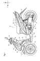
- Fig. 1 is a left side view of the entire motorcycle 10 according to the present invention.
- the front, rear, left, and right refer to these directions viewed from a rider seated on the seat 17 of the motorcycle 10 that will be described.
- the arrow F in the drawings indicates the forward direction of the motorcycle 10.
- the arrow U in the drawings indicates the upward direction of the motorcycle 10.
- the arrow R in the drawings indicates the rightward direction of the motorcycle 10.
- the arrow L indicates the leftward direction of the motorcycle 10.
- the center in the vehicle widthwise direction refers to a center in the widthwise direction of the vehicle body.
- the vehicle widthwise center refers to the position of the center when the motorcycle is viewed from the front.
- the outer side in the vehicle-widthwise direction indicates a direction toward the right or left from the vehicle-widthwise center.
- the inner side in the vehicle-widthwise direction indicates a direction toward the vehicle-widthwise center from the right or left.
- the motorcycle 10 includes a vehicle main body 11, a front wheel 12 provided at a front part of the motorcycle 10, and a rear wheel 14 provided at a rear part of the motorcycle 10.
- the vehicle main body 11 mainly includes a vehicle body frame 15, a handle 16, the seat 17, and a power unit 18.
- the vehicle body frame 15 supports the power unit 18, the seat 17, and the like.
- the power unit 18 includes an engine 19 and a driving system.
- the vehicle body frame 15 is indicated by a broken line in Fig. 1 .
- the vehicle body frame 15 includes a head pipe 20.
- the head pipe 20 is inclined downward in the forward direction.
- a steering shaft 70 is inserted in the head pipe 20 in a rotatable manner.
- the handle 16 is attached at an upper end of the steering shaft 21.
- a pair of front forks 21 is connected to a lower end of the steering shaft 70 through a bracket.
- the front wheel 12 is attached at lower ends of the front forks 21 in a rotatable manner.
- the vehicle body frame 15 includes a front frame 151 that is inclined downward in the backward direction from the head pipe 20.
- the vehicle body frame 15 is covered with a vehicle body cover 22.
- the vehicle body cover 22 is for example made of synthetic resin.
- the vehicle body cover 22 has a footboard 23, an under cover 231, a front cover 24, a rear cover 25, a handle cover 26, a front fender 27, a rear fender 28, and a side cover 29.
- the footboard 23 is provided under and ahead of the seat 17.
- the footboard 23 extends in a front-back direction.
- the under cover 231 is provided under the footboard 23.
- the under cover 231 extends in the front-back direction
- the rear cover 25 is provided behind the front cover 24.
- the rear cover 25 is provided behind the head pipe 20.
- the rear cover 25 extends in the up-down direction.
- the rear cover 25 is provided behind the front frame 151.
- the handle cover 26 covers a part of the handle 16.
- the handle cover 26 is provided above the front cover 24.
- the front fender 27 is provided above the front wheel 12.
- the front fender 27 is provided under the front cover 24.
- the front fender 27 is provided to project ahead of the front cover 24.
- the rear fender 28 is provided above the rear wheel 14.
- the side cover 29 is provided under the seat 17.
- the side cover 29 is positioned above the rear wheel 14.
- the side cover 29 extends backward from under the seat 17.
- the handle 16 is provided ahead of the seat 17.
- the handle 16 extends in the left-right direction. Grips that can be held by a rider are provided at the ends of the handle 16.
- the seat 17 is provided above the power unit 18.
- a storage space capable of storing items such as a helmet is provided under the seat 17.
- the power unit 18 is provided in the vicinity of the rear wheel 14.
- a CVT case 31 provided in the power unit 18 is exposed from the vehicle body cover 22.
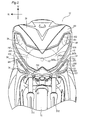
- Fig. 2 is a partly enlarged view of the motorcycle 10 as viewed from the front.
- the handle 16 and the handle cover 26 are not shown.
- the front forks 21 include a first front fork 211 and a second fork 212.
- the first front fork 211 is provided on the right side of the front wheel 12 in the vehicle-widthwise direction.
- the second front fork 212 is provided on the left side of the front wheel 12.
- the front cover 24 is provided above the front wheel 12.
- the front cover 24 is provided with the headlight 32, a first position light 33, a second position light 34, a first flasher 35, and a second flasher 36.
- the front cover 24 includes a first front cover 241, a second front cover 37, and a third front cover 38 (that corresponds to a second front cover according to the present invention).
- the first front cover 241, the second front cover 37, and the third front cover 38 are formed by a single member.
- the first front cover 241 is provided in the center in the vehicle-widthwise direction.
- the first front cover 241 is positioned above the front wheel 12 when viewed from the front.
- the first front cover 241 is connected to the rear cover 25.
- the second front cover 37 is positioned under and on the left side of the first front cover 241.
- the right end of the second front cover 37 is positioned above the second front fork 212.
- the second front cover 37 is provided on the left side of the front wheel 12 when viewed from the front.
- the left end of the third front cover 38 is positioned above the first front fork 211.
- the third front cover 38 is provided on the right side of the front wheel 12 when viewed from the front.
- the headlight 32 illuminates ahead of the motorcycle 10.
- the headlight 32 includes a headlight bulb 321, a headlight reflector 322, and a headlight cover 323.
- the headlight 32 is provided in the center of the front cover 24 in the vehicle widthwise direction.
- the headlight bulb 321 emits light.
- the headlight bulb 321 is provided in the center of the headlight 32 in the vehicle widthwise direction.
- the headlight bulb 321 is positioned below the center of the front cover 24 in the up-down direction of the vehicle widthwise center of the front cover 24.
- the headlight reflector 322 reflects a part of light from the headlight bulb 321 in the forward direction.
- the headlight reflector 322 is provided around the headlight bulb 321.
- the headlight reflector 322 extends radially forward from the back of the headlight bulb 321.
- the headlight reflector 322 has a larger width in the vehicle-widthwise direction than its size in the up-down direction.
- the headlight cover 323 covers the front of the headlight bulb 321 and the headlight reflector 322. Light emitted from the headlight bulb 321 passes through the headlight cover 323.
- the first position light 33 is provided at the second front cover 37.
- the first position light 33 includes a position light bulb 331, a position light reflector 332, and a position light cover 333.
- the first position light 33 is provided on the outer side of the headlight 32 in the vehicle widthwise direction.
- the first position light 33 is provided on the left side of the headlight 33 in the vehicle widthwise direction.
- the first position light 33 is positioned below the headlight bulb 321. A part of the first position light 33 overlaps the headlight 32 in the height-wise direction (vertical direction).
- the position light bulb 331 emits light.
- the position light bulb 331 is positioned on the left side of the headlight reflector 322 in the vehicle widthwise direction.
- the position light bulb 331 is positioned below the headlight bulb 321 in the up-down direction.
- the position light reflector 332 reflects light from the position light bulb 331.
- An upper end of the position light reflector 332 is positioned on the left side of the headlight reflector 322.
- a right end of the position light reflector 332 overlaps the headlight reflector 322 in the vehicle widthwise direction.
- a lower end of the position light reflector 332 is positioned below a lower end of the headlight 32.
- the position light cover 333 covers the position light bulb 331 and the position light reflector 332.
- the second position light 34 has the same structure as that of the first position light 33, and therefore a detailed description thereof will not be provided.
- the second position light 34 is provided in a position symmetrical to the first position light 33 with respect to the vehicle widthwise center.
- the second position light 34 is provided at the third front cover 38.
- the first flasher 35 includes a flasher bulb 351, a flasher reflector 352, and a flasher cover 353.
- the first flasher 35 is positioned more on the outer side than the headlight 32 in the vehicle widthwise direction.
- the first flasher 35 is positioned on the left side of the headlight 32.
- a part of the first flasher 35 overlaps a part of the first position light 33 in the vehicle widthwise direction.
- the first flasher 35 is positioned above the first position light 33.
- the first flasher 35 is positioned above the headlight 32.
- the flasher bulb 351 emits light.
- the flasher bulb 351 is positioned above an upper end of the headlight 32.
- the flasher bulb 351 is positioned more on the outer side than the position light bulb 331 of the position light 33 in the vehicle widthwise direction.
- the flasher reflector 352 reflects light from the flasher bulb 351.
- the flasher reflector 352 is provided around the flasher bulb 351.
- a lower end of the flasher reflector 352 is positioned above an upper end of the headlight 32.
- a vehicle widthwise outer end of the flasher reflector 352 is positioned more on the outer side than a vehicle widthwise outer end of the position light reflector 332.
- the flasher cover 353 covers the flasher bulb 351 and the flasher reflector 352.
- the flasher cover 353 is integrally formed with the headlight cover 323.
- the headlight 32, the first flasher 35, and the second flasher 36 together form the light unit.
- the headlight bulb 321, the flasher bulb 351, the headlight reflector 322 and the flasher reflector 352 are provided in a space surrounded by the light cover including the headlight cover 323 and the flasher cover 353 and a housing for the light unit.
- the second flasher 36 has the same structure as that of the first flasher 35 and therefore a detailed description thereof is not provided.
- the second flasher 36 is provided in a position symmetrical to the first flasher 35 with respect to the vehicle widthwise center.
- the first front cover 241 is provided with the headlight 32.
- the first front cover 241 includes a light positioning portion 245. In the light positioning portion 245, the headlight 32, the first flasher 35, and the second flasher 36 are provided.
- the light positioning portion 245 includes an opening 246 through which the headlight cover 323 is exposed.
- the first front cover 241 includes a lower cover 242 positioned under the headlight 32.
- the lower cover 242 is positioned in the center of the front cover 24 in the vehicle-widthwise direction.
- the first front cover 241 includes a side cover portion 247 provided between the headlight cover 323 and the position light cover 333.
- the side cover portion 247 is provided between the headlight cover 323 and the position light cover 333 when viewed from a side.
- the side cover portion 247 includes two inclined surfaces 247a and 247b inclined at different angles.
- the border line 247c between the two inclined surfaces 247a and 247b of the side cover portion 247 extend upward and outward in the vehicle-widthwise direction when viewed from the front.
- the second front cover 37 is provided with the first position light 33.
- the second front cover 37 includes a first light positioning portion 371 at which the first position light 33 can be provided.
- the first light positioning portion 371 has an opening 372 that can expose a part of the position light cover 333.
- a part of the second front cover 37 overlaps the headlight 32 in the vehicle-widthwise direction.
- a part of the second front cover 37 overlaps the headlight 32 in the up-down direction.
- the second front cover 37 is positioned under the first flasher 35.
- a part of the second front cover 37 overlaps the first flasher 35 in the vehicle widthwise direction.
- the third front cover 38 has the same structure as that of the second front cover 37 and therefore a detailed description thereof is not provided.
- the third front cover 38 is provided symmetrically to the second front cover 37 with respect to the vehicle-widthwise center.
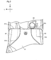
- Fig. 3 is a view of a rear cover 25 seen from the back. Fig. 3 shows a part of the rear cover 25.
- the rear cover 25 is provided with an ignition keyhole 255.
- the rear cover 25 has first and second pockets 251 and 252.
- the first pocket 251 is provided on the left side of the vehicle-widthwise center.
- the first pocket 251 can store items.
- the first pocket 251 has a first opening 251a at its upper end.
- the first pocket 251 extends downward from the first opening 251a.
- the first pocket 251 has a first bottom 251b at its lower end.
- the second pocket 252 is provided on the right side of the vehicle-widthwise center.
- the second pocket 252 has a second opening 252a and a second bottom 252b.
- the second pocket can store items.
- the second pocket 252 has the second opening 252a at its upper end.
- the second pocket 252 extends downward from the second opening 252a.
- the second pocket 252 has the second bottom 252b at its lower end.
- the second bottom 252b is positioned above the first bottom 251b.
- the second pocket 252 has a different depth from that of the first pocket 251.
- the depth of the second pocket 252 is smaller than that of the first pocket 251.
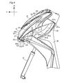
- Fig. 4 is a partly side view of the front cover 24 and the rear cover 25 viewed from the outer side in vehicle-widthwise direction. In Fig. 4 , the rear wheel 12 is not shown.
- the first front cover 241 is inclined upward in the backward direction.
- a front end line of the first front cover 241 when viewed from a side is inclined upward in the backward direction.
- the front end line of the first front cover 241 when viewed from a side is arch-shaped.
- the parts of the headlight cover 323 and the flasher cover 353 exposed from the first front cover 241 are inclined upward in the backward direction.
- the front end 373 of the second front cover 37 is positioned behind the front end of the front cover 24.
- the front end 373 of the second front cover 37 is positioned behind the front end of the lower cover 242.
- the first positioning portion 371 is inclined upward in the backward direction.
- the position light cover 333 includes a flat portion 333a.
- the flat portion 333a is exposed from the opening 372 of the second front cover 37.
- the flat portion 333a is inclined upward in the backward direction.
- the flat portion 333a extends in the vehicle-widthwise direction and the left and right ends of the flat portion 333a are inclined at substantially equal angles with respect to the horizontal plane. Therefore, the flat portion 333a can hardly be recognized in a side view.
- the headlight bulb 321 is positioned behind the first position light 33 in the front-back direction.
- the headlight bulb 321 is positioned ahead of the first flasher bulb 351 in the front-back direction.
- the first position light bulb 331 is positioned ahead of the first flasher bulb 351.
- the first pocket 251 is positioned behind the headlight bulb 321 and the position light bulb 331.
- the first opening 251a of the first pocket 251 is positioned below the first flasher bulb 351.
- the upper end 251e of the first pocket 251 is positioned at a rear end of the first opening 251a.
- the first bottom 251b of the first pocket 251 overlaps the headlight bulb 321 in the up-down direction.
- the first bottom 251b of the first pocket 251 is positioned above the position light bulb 331.
- the first bottom 251b of the first pocket 251 includes a surface inclined downward in the backward direction.
- the lower end 251d of the first bottom 251b is positioned at a rear part of the first bottom 251b.
- the first pocket 251 is inclined downward and forward from the first opening 251a.
- the front end 251c of the first pocket 251 overlaps the first flasher bulb 351 in the front-back direction.
- the first bottom 251b overlaps an upper end of the flasher cover 353 in the front-back direction.
- FIG. 5 is a front view of the front cover 24.
- the first and second pockets 251 and 252 are indicated by broken lines.
- the first pocket 251 is positioned on the outer side of the headlight bulb 321 in the vehicle-widthwise direction.
- the first pocket 251 is positioned on the outer side of the head pipe 20 in the vehicle-widthwise direction.
- the first pocket 251 is positioned on the left side of the headlight bulb 321.
- a part of the first pocket 251 overlaps the headlight reflector 322 in the vehicle-widthwise direction.
- the lower end 251d of the first pocket 251 is positioned above the position light bulb 331 in the up-down direction.
- the lower end 251d of the first pocket 251 is positioned below the upper end of the position light cover 333 in the up-down direction.
- the upper end 251e of the first pocket 251 is positioned below the flasher bulb 351.
- the upper end 251e of the first pocket 251 is positioned above the lower end of the flasher reflector 352.
- the first pocket 251 overlaps the flasher bulb 351 and the position light bulb 331 in the vehicle-widthwise direction.
- the position light bulb 331 is positioned below the first bottom 251b of the first pocket 251.
- the second pocket 252 has the same structure as that of the first pocket 251 but its width in the vehicle-widthwise direction is greater than that of the first pocket 251.
- the second pocket 252 is positioned more on the outer side than the vehicle widthwise outer end of the headlight reflector 322 in the vehicle-widthwise direction.
- the position light 33 is not provided under the headlight bulb 321. According to the embodiment, the position light 33 is provided on the outer side of the headlight 32 in the vehicle-widthwise direction. Therefore, according to the embodiment, light from the headlight bulb 321 and light from the position light bulb 331 can be distinguished from each other more easily.
- the first and second pockets 251 and 252 are provided on the outer side of the headlight bulb 321 in the vehicle-widthwise direction.
- the first pocket 251 is positioned above the position light bulb 331.
- the first pocket 251 is provided below the flasher bulb 351. Therefore, according to the embodiment described above, the flasher bulb 351 and the first position light 33 can be prevented from limiting the size of the first pocket 251.
- the first position light 33 is provided on the outer side of the headlight 32 in the vehicle-widthwise direction. According to the embodiment, the upper end of the first position light 33 is provided in a position overlapping the first bottom 251b of the first pocket 251 in the up-down direction. Therefore, if the first position light 33 is positioned in the back, the size of the first pocket 251 is hardly limited, so that the first pocket 251 may have a sufficient size.
- the handle cover 26 is provided above the front cover 24 and therefore the space that can be used to provide the headlight 32 and the like is limited. According to the embodiment, light from the headlight bulb 321 and light from the position light bulb 331 can be distinguished from each other more easily, so that the front cover 24 can be prevented from becoming large in size and the first pocket 251 can have a sufficient size.
- the front end of the second front cover 37 is provided behind the front end of the first front cover 241. If the front end of the second front cover 37 is positioned in the same position in the front-back direction as the front end of the first front cover 241, the front surface of the first front cover 241 is substantially continuous with the front surface of the second front cover 37. In this arrangement, it may look as if the widthwise length of the front cover is large and give an impression of not being compact. As the second front cover 37 is provided in the back, the front surface of the first front cover 241 is not continuous with the front surface of the second front cover 37, so that the front cover 24 may have a compact structure.
- the position of the pocket and the position of the position light overlaps, which may reduce the size of the pocket.
- the first pocket 251 is kept from becoming small in size. Therefore, the first pocket 251 may have a sufficient size and the second front cover 37 can be provided behind the first front cover 241, so that the front cover 24 can be provided in a compact form.
- the first position light 33 includes the flat portion 333a.
- the flat portion 333a is exposed from the opening 372 of the second front cover 37.
- the headlight 32 can be recognized from the outer side in the vehicle widthwise direction more easily than the case in which the first position light 33 is exposed from the opening 372. If the first position light 33 is exposed from the opening 372, the headlight 32 must be moved forward in order to allow the headlight 32 to be recognized more easily from the outer side in the vehicle widthwise direction.
- the part of the first position light 33 exposed from the opening 372 is flat-shaped, so that the headlight 32 does not have to be moved forward, and the front cover 24 can be prevented from being prolonged in the front-back direction by the forward movement of the headlight 32.
- the flat portion 333a of the position light 33 is exposed from the opening 372 of the second front cover 37. Therefore, as compared to the case in which the position light cover is viewed in a side view, the position light can be provided in a compact shape in the front-back direction, so that the front cover 24 can be prevented from becoming large in size.
- the headlight reflector 322 and the position bulb 331 overlap in the front-back direction. Therefore, the position light bulb 331 is positioned ahead of the first pocket 251 in the front-back direction but does not restrict the size of the first pocket 251.
- the position light bulb 331 and the flasher bulb 351 are positioned on the outer side than the vehicle widthwise end of the headlight reflector 322. Therefore, in the above-described embodiment, the headlight 32 can have a sufficient size.
- the lower end of the first position light 33 is positioned below the lower end of the headlight 32. Therefore, in the embodiment, the first position light 33 is less likely to prevent the headlight 32 from becoming large in size.
- the lower end of the flasher cover 353 is positioned ahead of the first opening 251a.
- the flasher bulb 351 is positioned above the first opening 251a. Therefore, the flasher 35 does not occlude the first opening 251a of the first pocket 251, so that items can be placed in the first pocket 251 more easily.
- the first pocket 251 is provided on the outer side in the vehicle widthwise direction of the head pipe 20.
- the head pipe 20 is inclined downward in the forward direction.
- a space for rider's feet can be formed easily on the outer side of the head pipe 20 in the vehicle widthwise direction. According to the embodiment, the space to place the rider's feet is secured and the first pocket 251 can be large.
- the scooter type motorcycle according to the embodiment has been described but the invention is not limited to this example and may be applied to a three-wheel or a four-wheel saddle riding type vehicle.
- the front cover 24 includes the first front cover 241, the second front cover 37, and the third front cover 38 in a discrete form, while the invention is not limited to this arrangement.
- the front cover 24 the first front cover 241, the second front cover 37, and the third front cover 38 may be formed integrally.
- the first pocket 251 is inclined forward and downward.
- the first pocket 251 may have a different shape.
- the first pocket 251 may have a shape that extends in the up-down direction.
- the footboard 23 is flat, but the invention is not limited to this example.
- a part of the footboard may be expanded or raised as compared to the other part.
- the first pocket 251 satisfies a relation as recited in claim 1.
- the second pocket 252 may satisfy the relation as recited in claim 1.
- the pocket that satisfies the relation as recited in claim 1 can have a sufficient size.
- the first and second pockets 251 and 252 have different depths.
- the first and second pockets 251 and 252 may have the same depth.
- the first pocket 251 may be shallower than the second pocket 252.
- the first front cover 241, the second front cover 37, and the third front cover 38 are formed integrally.
- the first front cover 241, the second front cover 37, and the third front cover 38 may be formed discretely and the manner of dividing the cover is not limited to that of the above-described embodiment.
- the headlight and the flasher are formed integrally.
- the invention is not limited to this example and the headlight and the flasher may be formed discretely.
- the headlight, the flasher, and the position light may be formed integrally.
Landscapes
- Engineering & Computer Science (AREA)
- Mechanical Engineering (AREA)
- Lighting Device Outwards From Vehicle And Optical Signal (AREA)
- Non-Portable Lighting Devices Or Systems Thereof (AREA)
Abstract
Description
- The present invention relates to a saddle riding type vehicle, and more specifically to a saddle riding type vehicle provided with a handle cover and a front cover.
- A motorcycle is known as one of saddle riding type vehicles. A motorcycle disclosed by
JP-A 2007-283927 - It is an object of the present invention to provide a saddle riding type vehicle provided with a sufficiently large pocket that allows light from a headlight bulb and light from a position light to be distinguished from each other more easily and a front cover to be kept from becoming large in size in the up-down direction.
- This object is achieved by a saddle riding type vehicle according to
claim 1. - In the motorcycle disclosed by
JP-A 2007-283927 - In order to distinguish light from the headlight bulb and light from the position light, the position light may be provided on the outer side of the headlight in the vehicle widthwise direction.
- If the position light is provided on the outer side of the headlight in the vehicle widthwise direction, however, the position of the pocket and the position of the position light overlap, so that the pocket can be reduced in size.
- In order to prevent the pocket from becoming smaller in size by shifting the position of the position light from the position of the pocket in an up-down (vertical) direction, the width of the front cover in the up-down direction may be increased. If the width of the front cover in the up-down direction is increased, however, the position of the handle cover moves upward. In other words, the arrangement with a front cover having an increased width in the up-down direction makes it difficult for the rider to ride the vehicle.
- A saddle riding type vehicle according to the present invention includes a head pipe, a steering shaft, a handle, a handle cover, a front cover, a rear cover, a footboard, a headlight, a pocket, a position light, and a flasher. The steering shaft is inserted in the head pipe rotatably relative to the head pipe. The handle is connected to an upper part of the steering shaft. The handle cover covers the handle. The front cover covers a front part of the head pipe and is inclined upward and backward from the front. The rear cover covers a rear part of the head pipe and extends at least in the up-down direction. The footboard is connected to a lower part of the rear cover. The headlight is attached in a center of the front cover in the vehicle widthwise direction. The pocket is provided at the rear cover on an outer side of the head pipe in the vehicle widthwise direction and in a position that overlaps the headlight in the up-down direction. The position light is attached to the front cover and provided in a position that overlaps the pocket in the vehicle widthwise direction. The flasher is attached to the front cover and provided above the position light. The headlight includes a headlight bulb. The flasher includes a flasher bulb. The pocket includes a first opening and a bottom. The pocket extends as it is inclined forward and downward from the first opening. The bottom is positioned at a lower end of the pocket. An upper end of the position light overlaps the bottom in the up-down direction. The position light is provided in such a position that at least a part of the position light overlaps the headlight in a height-wise direction. The headlight bulb is positioned in a center in the vehicle widthwise direction. The flasher bulb is positioned above the pocket.
- Here, the position light is not positioned below the headlight bulb. This makes it easier to distinguish between light from the headlight bulb and light from the position light. In the above-described saddle riding type vehicle, an upper end of the position light is in a position that overlaps the bottom of the pocket in the up-down direction. Here, the flasher bulb is positioned above the pocket. An upper end of the position light is in a position that overlaps the bottom of the pocket. Therefore, the pocket can be kept from becoming small because of the positioning of the position light and the pocket can have a sufficiently large size. Therefore, in the above-described saddle riding type vehicle, light from the headlight bulb and light from the position light can be distinguished from each other more easily, the front cover can be prevented from becoming large in size, and the pocket can have a sufficiently large size.
-
-
Fig. 1 is a left side view of an overall structure of a motorcycle according to an embodiment of the present invention. -
Fig. 2 is an overview of a front surface of a front cover. -
Fig. 3 is a view of a rear cover seen from the rider's side. -
Fig. 4 is a side view of the front cover viewed from a side. -
Fig. 5 is a view showing the positional relation among a headlight, a position light, a flasher, and a pocket. - In an arrangement in which the front cover of a motorcycle is provided with a headlight, a position light, and a flasher, if the bulb of the position light is provided under the bulb of the headlight, light from the headlight and light from the position light overlap and these kinds of light cannot easily be distinguished from each other.
- The position light may be provided on the outer side of the headlight in the vehicle-widthwise direction so that light from the headlight bulb and light from the position light bulb can be distinguished from each other. However, if the position light is simply provided on the outer side of the headlight in the vehicle-widthwise direction, the position of the pocket and the position of the position light can overlap, which reduces the size of the pocket.
- It may be possible to increase the width of the front cover in the up-down direction in order to prevent the pocket from becoming small in size because of the vertical shift between the positions of the position light and the pocket. If the size of the front cover in the vehicle widthwise direction increases, however, the position of the handle cover changes in the upward direction. Therefore, the increase in the size of the front cover in the vehicle widthwise direction makes it difficult for a rider to ride the vehicle.
- The inventor came up with an idea of preventing the front cover from increasing in size and still allowing the pocket to have a sufficient size based on a positional arrangement of a position light, a headlight, a flasher, and a pocket.
- The inventor employed an arrangement in which the bulb of the position light is not positioned under the headlight bulb. In this way, light from the headlight bulb and light from the position light bulb can be distinguished from each other.
- The inventor provided a pocket on the outer side of a head pipe in the vehicle width-wise direction and a position light in a position overlapping the pocket in the vehicle widthwise direction. The inventor employed an arrangement in which an upper end of the position light overlaps a bottom part of the pocket in the up-down direction. Therefore, a pocket with a sufficient size can be secured even when the position light is provided in the back.
- Now, a saddle riding type vehicle according to an embodiment of the present invention will be described in conjunction with the accompanying drawings. Note that in the following, a
scooter type motorcycle 10 will be described as an example of the saddle riding type vehicle. In the drawings, the same or corresponding portions are designated by the same reference characters and their description will not be repeated. -
Fig. 1 is a left side view of theentire motorcycle 10 according to the present invention. Note that in the following description, the front, rear, left, and right refer to these directions viewed from a rider seated on theseat 17 of themotorcycle 10 that will be described. In the following, the arrow F in the drawings indicates the forward direction of themotorcycle 10. The arrow U in the drawings indicates the upward direction of themotorcycle 10. The arrow R in the drawings indicates the rightward direction of themotorcycle 10. The arrow L indicates the leftward direction of themotorcycle 10. Here, the center in the vehicle widthwise direction refers to a center in the widthwise direction of the vehicle body. In other word, the vehicle widthwise center refers to the position of the center when the motorcycle is viewed from the front. The outer side in the vehicle-widthwise direction indicates a direction toward the right or left from the vehicle-widthwise center. The inner side in the vehicle-widthwise direction indicates a direction toward the vehicle-widthwise center from the right or left. - The
motorcycle 10 includes a vehiclemain body 11, afront wheel 12 provided at a front part of themotorcycle 10, and arear wheel 14 provided at a rear part of themotorcycle 10. - The vehicle
main body 11 mainly includes avehicle body frame 15, ahandle 16, theseat 17, and apower unit 18. - The
vehicle body frame 15 supports thepower unit 18, theseat 17, and the like. Thepower unit 18 includes anengine 19 and a driving system. Thevehicle body frame 15 is indicated by a broken line inFig. 1 . Thevehicle body frame 15 includes ahead pipe 20. Thehead pipe 20 is inclined downward in the forward direction. A steeringshaft 70 is inserted in thehead pipe 20 in a rotatable manner. Thehandle 16 is attached at an upper end of the steeringshaft 21. A pair offront forks 21 is connected to a lower end of the steeringshaft 70 through a bracket. Thefront wheel 12 is attached at lower ends of thefront forks 21 in a rotatable manner. Thevehicle body frame 15 includes a front frame 151 that is inclined downward in the backward direction from thehead pipe 20. - The
vehicle body frame 15 is covered with avehicle body cover 22. Thevehicle body cover 22 is for example made of synthetic resin. Thevehicle body cover 22 has afootboard 23, an undercover 231, afront cover 24, arear cover 25, ahandle cover 26, afront fender 27, arear fender 28, and aside cover 29. - The
footboard 23 is provided under and ahead of theseat 17. Thefootboard 23 extends in a front-back direction. The undercover 231 is provided under thefootboard 23. The undercover 231 extends in the front-back direction - The
front cover 24 is positioned ahead of theseat 17. Thefront cover 24 is positioned ahead of thehead pipe 20. Thefront cover 24 is provided with aheadlight 32. - The
rear cover 25 is provided behind thefront cover 24. Therear cover 25 is provided behind thehead pipe 20. Therear cover 25 extends in the up-down direction. Therear cover 25 is provided behind the front frame 151. - The
handle cover 26 covers a part of thehandle 16. Thehandle cover 26 is provided above thefront cover 24. - The
front fender 27 is provided above thefront wheel 12. Thefront fender 27 is provided under thefront cover 24. Thefront fender 27 is provided to project ahead of thefront cover 24. Therear fender 28 is provided above therear wheel 14. - The side cover 29 is provided under the
seat 17. The side cover 29 is positioned above therear wheel 14. The side cover 29 extends backward from under theseat 17. - The
handle 16 is provided ahead of theseat 17. Thehandle 16 extends in the left-right direction. Grips that can be held by a rider are provided at the ends of thehandle 16. - The
seat 17 is provided above thepower unit 18. A storage space capable of storing items such as a helmet is provided under theseat 17. - The
power unit 18 is provided in the vicinity of therear wheel 14. ACVT case 31 provided in thepower unit 18 is exposed from thevehicle body cover 22. -
Fig. 2 is a partly enlarged view of themotorcycle 10 as viewed from the front. InFig. 2 , thehandle 16 and thehandle cover 26 are not shown. - The
front forks 21 include a firstfront fork 211 and asecond fork 212. The firstfront fork 211 is provided on the right side of thefront wheel 12 in the vehicle-widthwise direction. The secondfront fork 212 is provided on the left side of thefront wheel 12. Thefront cover 24 is provided above thefront wheel 12. - The
front cover 24 is provided with theheadlight 32, a first position light 33, a second position light 34, afirst flasher 35, and asecond flasher 36. Thefront cover 24 includes a firstfront cover 241, a secondfront cover 37, and a third front cover 38 (that corresponds to a second front cover according to the present invention). The firstfront cover 241, the secondfront cover 37, and the thirdfront cover 38 are formed by a single member. - The first
front cover 241 is provided in the center in the vehicle-widthwise direction. The firstfront cover 241 is positioned above thefront wheel 12 when viewed from the front. The firstfront cover 241 is connected to therear cover 25. The secondfront cover 37 is positioned under and on the left side of the firstfront cover 241. The right end of the secondfront cover 37 is positioned above the secondfront fork 212. The secondfront cover 37 is provided on the left side of thefront wheel 12 when viewed from the front. The left end of the thirdfront cover 38 is positioned above the firstfront fork 211. The thirdfront cover 38 is provided on the right side of thefront wheel 12 when viewed from the front. - The
headlight 32 illuminates ahead of themotorcycle 10. Theheadlight 32 includes aheadlight bulb 321, aheadlight reflector 322, and aheadlight cover 323. Theheadlight 32 is provided in the center of thefront cover 24 in the vehicle widthwise direction. - The
headlight bulb 321 emits light. Theheadlight bulb 321 is provided in the center of theheadlight 32 in the vehicle widthwise direction. Theheadlight bulb 321 is positioned below the center of thefront cover 24 in the up-down direction of the vehicle widthwise center of thefront cover 24. - The
headlight reflector 322 reflects a part of light from theheadlight bulb 321 in the forward direction. Theheadlight reflector 322 is provided around theheadlight bulb 321. Theheadlight reflector 322 extends radially forward from the back of theheadlight bulb 321. Theheadlight reflector 322 has a larger width in the vehicle-widthwise direction than its size in the up-down direction. - The
headlight cover 323 covers the front of theheadlight bulb 321 and theheadlight reflector 322. Light emitted from theheadlight bulb 321 passes through theheadlight cover 323. - The first position light 33 is provided at the second
front cover 37. The first position light 33 includes a positionlight bulb 331, a positionlight reflector 332, and a positionlight cover 333. The first position light 33 is provided on the outer side of theheadlight 32 in the vehicle widthwise direction. The first position light 33 is provided on the left side of theheadlight 33 in the vehicle widthwise direction. The first position light 33 is positioned below theheadlight bulb 321. A part of the first position light 33 overlaps theheadlight 32 in the height-wise direction (vertical direction). - The position
light bulb 331 emits light. The positionlight bulb 331 is positioned on the left side of theheadlight reflector 322 in the vehicle widthwise direction. The positionlight bulb 331 is positioned below theheadlight bulb 321 in the up-down direction. - The position
light reflector 332 reflects light from the positionlight bulb 331. An upper end of the positionlight reflector 332 is positioned on the left side of theheadlight reflector 322. A right end of the positionlight reflector 332 overlaps theheadlight reflector 322 in the vehicle widthwise direction. A lower end of the positionlight reflector 332 is positioned below a lower end of theheadlight 32. - The position
light cover 333 covers the positionlight bulb 331 and the positionlight reflector 332. - The second position light 34 has the same structure as that of the first position light 33, and therefore a detailed description thereof will not be provided. The second position light 34 is provided in a position symmetrical to the first position light 33 with respect to the vehicle widthwise center. The second position light 34 is provided at the third
front cover 38. - The
first flasher 35 includes aflasher bulb 351, aflasher reflector 352, and aflasher cover 353. Thefirst flasher 35 is positioned more on the outer side than theheadlight 32 in the vehicle widthwise direction. Thefirst flasher 35 is positioned on the left side of theheadlight 32. A part of thefirst flasher 35 overlaps a part of the first position light 33 in the vehicle widthwise direction. Thefirst flasher 35 is positioned above thefirst position light 33. Thefirst flasher 35 is positioned above theheadlight 32. - The
flasher bulb 351 emits light. Theflasher bulb 351 is positioned above an upper end of theheadlight 32. Theflasher bulb 351 is positioned more on the outer side than the positionlight bulb 331 of the position light 33 in the vehicle widthwise direction. - The
flasher reflector 352 reflects light from theflasher bulb 351. Theflasher reflector 352 is provided around theflasher bulb 351. A lower end of theflasher reflector 352 is positioned above an upper end of theheadlight 32. A vehicle widthwise outer end of theflasher reflector 352 is positioned more on the outer side than a vehicle widthwise outer end of the positionlight reflector 332. - The
flasher cover 353 covers theflasher bulb 351 and theflasher reflector 352. Theflasher cover 353 is integrally formed with theheadlight cover 323. Theheadlight 32, thefirst flasher 35, and thesecond flasher 36 together form the light unit. Theheadlight bulb 321, theflasher bulb 351, theheadlight reflector 322 and theflasher reflector 352 are provided in a space surrounded by the light cover including theheadlight cover 323 and theflasher cover 353 and a housing for the light unit. - The
second flasher 36 has the same structure as that of thefirst flasher 35 and therefore a detailed description thereof is not provided. Thesecond flasher 36 is provided in a position symmetrical to thefirst flasher 35 with respect to the vehicle widthwise center. - The first
front cover 241 is provided with theheadlight 32. The firstfront cover 241 includes alight positioning portion 245. In thelight positioning portion 245, theheadlight 32, thefirst flasher 35, and thesecond flasher 36 are provided. Thelight positioning portion 245 includes anopening 246 through which theheadlight cover 323 is exposed. The firstfront cover 241 includes alower cover 242 positioned under theheadlight 32. Thelower cover 242 is positioned in the center of thefront cover 24 in the vehicle-widthwise direction. The firstfront cover 241 includes aside cover portion 247 provided between theheadlight cover 323 and the positionlight cover 333. Theside cover portion 247 is provided between theheadlight cover 323 and the positionlight cover 333 when viewed from a side. Theside cover portion 247 includes twoinclined surfaces border line 247c between the twoinclined surfaces side cover portion 247 extend upward and outward in the vehicle-widthwise direction when viewed from the front. - The second
front cover 37 is provided with thefirst position light 33. The secondfront cover 37 includes a firstlight positioning portion 371 at which the first position light 33 can be provided. The firstlight positioning portion 371 has anopening 372 that can expose a part of the positionlight cover 333. A part of the secondfront cover 37 overlaps theheadlight 32 in the vehicle-widthwise direction. A part of the secondfront cover 37 overlaps theheadlight 32 in the up-down direction. The secondfront cover 37 is positioned under thefirst flasher 35. A part of the secondfront cover 37 overlaps thefirst flasher 35 in the vehicle widthwise direction. - The third
front cover 38 has the same structure as that of the secondfront cover 37 and therefore a detailed description thereof is not provided. The thirdfront cover 38 is provided symmetrically to the secondfront cover 37 with respect to the vehicle-widthwise center. -
Fig. 3 is a view of arear cover 25 seen from the back.Fig. 3 shows a part of therear cover 25. - The
rear cover 25 is provided with anignition keyhole 255. Therear cover 25 has first andsecond pockets - The
first pocket 251 is provided on the left side of the vehicle-widthwise center. Thefirst pocket 251 can store items. Thefirst pocket 251 has afirst opening 251a at its upper end. Thefirst pocket 251 extends downward from thefirst opening 251a. Thefirst pocket 251 has afirst bottom 251b at its lower end. - The
second pocket 252 is provided on the right side of the vehicle-widthwise center. Thesecond pocket 252 has asecond opening 252a and asecond bottom 252b. The second pocket can store items. Thesecond pocket 252 has thesecond opening 252a at its upper end. Thesecond pocket 252 extends downward from thesecond opening 252a. Thesecond pocket 252 has thesecond bottom 252b at its lower end. Thesecond bottom 252b is positioned above thefirst bottom 251b. Thesecond pocket 252 has a different depth from that of thefirst pocket 251. The depth of thesecond pocket 252 is smaller than that of thefirst pocket 251. -
Fig. 4 is a partly side view of thefront cover 24 and therear cover 25 viewed from the outer side in vehicle-widthwise direction. InFig. 4 , therear wheel 12 is not shown. - The first
front cover 241 is inclined upward in the backward direction. A front end line of the firstfront cover 241 when viewed from a side is inclined upward in the backward direction. The front end line of the firstfront cover 241 when viewed from a side is arch-shaped. The parts of theheadlight cover 323 and theflasher cover 353 exposed from the firstfront cover 241 are inclined upward in the backward direction. - The
front end 373 of the secondfront cover 37 is positioned behind the front end of thefront cover 24. Thefront end 373 of the secondfront cover 37 is positioned behind the front end of thelower cover 242. In a side view, thefirst positioning portion 371 is inclined upward in the backward direction. The positionlight cover 333 includes aflat portion 333a. Theflat portion 333a is exposed from theopening 372 of the secondfront cover 37. In a side view, theflat portion 333a is inclined upward in the backward direction. Theflat portion 333a extends in the vehicle-widthwise direction and the left and right ends of theflat portion 333a are inclined at substantially equal angles with respect to the horizontal plane. Therefore, theflat portion 333a can hardly be recognized in a side view. - The
headlight bulb 321 is positioned behind the first position light 33 in the front-back direction. Theheadlight bulb 321 is positioned ahead of thefirst flasher bulb 351 in the front-back direction. The first positionlight bulb 331 is positioned ahead of thefirst flasher bulb 351. - The
first pocket 251 is positioned behind theheadlight bulb 321 and the positionlight bulb 331. Thefirst opening 251a of thefirst pocket 251 is positioned below thefirst flasher bulb 351. Theupper end 251e of thefirst pocket 251 is positioned at a rear end of thefirst opening 251a. Thefirst bottom 251b of thefirst pocket 251 overlaps theheadlight bulb 321 in the up-down direction. Thefirst bottom 251b of thefirst pocket 251 is positioned above the positionlight bulb 331. Thefirst bottom 251b of thefirst pocket 251 includes a surface inclined downward in the backward direction. Thelower end 251d of thefirst bottom 251b is positioned at a rear part of thefirst bottom 251b. Thefirst pocket 251 is inclined downward and forward from thefirst opening 251a. Thefront end 251c of thefirst pocket 251 overlaps thefirst flasher bulb 351 in the front-back direction. Thefirst bottom 251b overlaps an upper end of theflasher cover 353 in the front-back direction. - Positional Relation between Pockets, Headlight, Position Light, and Flashers
Fig. 5 is a front view of thefront cover 24. InFig. 5 , the first andsecond pockets - The
first pocket 251 is positioned on the outer side of theheadlight bulb 321 in the vehicle-widthwise direction. Thefirst pocket 251 is positioned on the outer side of thehead pipe 20 in the vehicle-widthwise direction. Thefirst pocket 251 is positioned on the left side of theheadlight bulb 321. A part of thefirst pocket 251 overlaps theheadlight reflector 322 in the vehicle-widthwise direction. Thelower end 251d of thefirst pocket 251 is positioned above the positionlight bulb 331 in the up-down direction. Thelower end 251d of thefirst pocket 251 is positioned below the upper end of the positionlight cover 333 in the up-down direction. Theupper end 251e of thefirst pocket 251 is positioned below theflasher bulb 351. Theupper end 251e of thefirst pocket 251 is positioned above the lower end of theflasher reflector 352. Thefirst pocket 251 overlaps theflasher bulb 351 and the positionlight bulb 331 in the vehicle-widthwise direction. The positionlight bulb 331 is positioned below thefirst bottom 251b of thefirst pocket 251. - The
second pocket 252 has the same structure as that of thefirst pocket 251 but its width in the vehicle-widthwise direction is greater than that of thefirst pocket 251. Thesecond pocket 252 is positioned more on the outer side than the vehicle widthwise outer end of theheadlight reflector 322 in the vehicle-widthwise direction. - Now, features of the embodiment will be described.
- According to the embodiment described above, the position light 33 is not provided under the
headlight bulb 321. According to the embodiment, the position light 33 is provided on the outer side of theheadlight 32 in the vehicle-widthwise direction. Therefore, according to the embodiment, light from theheadlight bulb 321 and light from the positionlight bulb 331 can be distinguished from each other more easily. - According to the embodiment, the first and
second pockets headlight bulb 321 in the vehicle-widthwise direction. Thefirst pocket 251 is positioned above the positionlight bulb 331. Thefirst pocket 251 is provided below theflasher bulb 351. Therefore, according to the embodiment described above, theflasher bulb 351 and the first position light 33 can be prevented from limiting the size of thefirst pocket 251. - According to the embodiment, the first position light 33 is provided on the outer side of the
headlight 32 in the vehicle-widthwise direction. According to the embodiment, the upper end of the first position light 33 is provided in a position overlapping thefirst bottom 251b of thefirst pocket 251 in the up-down direction. Therefore, if the first position light 33 is positioned in the back, the size of thefirst pocket 251 is hardly limited, so that thefirst pocket 251 may have a sufficient size. - According to the embodiment, the
handle cover 26 is provided above thefront cover 24 and therefore the space that can be used to provide theheadlight 32 and the like is limited. According to the embodiment, light from theheadlight bulb 321 and light from the positionlight bulb 331 can be distinguished from each other more easily, so that thefront cover 24 can be prevented from becoming large in size and thefirst pocket 251 can have a sufficient size. - According to the embodiment, the front end of the second
front cover 37 is provided behind the front end of the firstfront cover 241. If the front end of the secondfront cover 37 is positioned in the same position in the front-back direction as the front end of the firstfront cover 241, the front surface of the firstfront cover 241 is substantially continuous with the front surface of the secondfront cover 37. In this arrangement, it may look as if the widthwise length of the front cover is large and give an impression of not being compact. As the secondfront cover 37 is provided in the back, the front surface of the firstfront cover 241 is not continuous with the front surface of the secondfront cover 37, so that thefront cover 24 may have a compact structure. However, depending on the positioning of the pocket, the position of the pocket and the position of the position light overlaps, which may reduce the size of the pocket. In the above-described embodiment, however, if the secondfront cover 37 is provided behind the firstfront cover 241, thefirst pocket 251 is kept from becoming small in size. Therefore, thefirst pocket 251 may have a sufficient size and the secondfront cover 37 can be provided behind the firstfront cover 241, so that thefront cover 24 can be provided in a compact form. - According to the above-described embodiment, the first position light 33 includes the
flat portion 333a. According to the above-describe embodiment, theflat portion 333a is exposed from theopening 372 of the secondfront cover 37. In this arrangement, theheadlight 32 can be recognized from the outer side in the vehicle widthwise direction more easily than the case in which the first position light 33 is exposed from theopening 372. If the first position light 33 is exposed from theopening 372, theheadlight 32 must be moved forward in order to allow theheadlight 32 to be recognized more easily from the outer side in the vehicle widthwise direction. According to the above-described embodiment, however, the part of the first position light 33 exposed from theopening 372 is flat-shaped, so that theheadlight 32 does not have to be moved forward, and thefront cover 24 can be prevented from being prolonged in the front-back direction by the forward movement of theheadlight 32. Theflat portion 333a of the position light 33 is exposed from theopening 372 of the secondfront cover 37. Therefore, as compared to the case in which the position light cover is viewed in a side view, the position light can be provided in a compact shape in the front-back direction, so that thefront cover 24 can be prevented from becoming large in size. - According to the above-describe embodiment, the
headlight reflector 322 and theposition bulb 331 overlap in the front-back direction. Therefore, the positionlight bulb 331 is positioned ahead of thefirst pocket 251 in the front-back direction but does not restrict the size of thefirst pocket 251. - According to the above-described embodiment, the position
light bulb 331 and theflasher bulb 351 are positioned on the outer side than the vehicle widthwise end of theheadlight reflector 322. Therefore, in the above-described embodiment, theheadlight 32 can have a sufficient size. - According to the above-described embodiment, the lower end of the first position light 33 is positioned below the lower end of the
headlight 32. Therefore, in the embodiment, the first position light 33 is less likely to prevent theheadlight 32 from becoming large in size. - According to the embodiment, the lower end of the
flasher cover 353 is positioned ahead of thefirst opening 251a. According to embodiment, theflasher bulb 351 is positioned above thefirst opening 251a. Therefore, theflasher 35 does not occlude thefirst opening 251a of thefirst pocket 251, so that items can be placed in thefirst pocket 251 more easily. - According to the above-described embodiment, the
first pocket 251 is provided on the outer side in the vehicle widthwise direction of thehead pipe 20. Thehead pipe 20 is inclined downward in the forward direction. A space for rider's feet can be formed easily on the outer side of thehead pipe 20 in the vehicle widthwise direction. According to the embodiment, the space to place the rider's feet is secured and thefirst pocket 251 can be large. - In the foregoing, the scooter type motorcycle according to the embodiment has been described but the invention is not limited to this example and may be applied to a three-wheel or a four-wheel saddle riding type vehicle.
- According to the embodiment, the
front cover 24 includes the firstfront cover 241, the secondfront cover 37, and the thirdfront cover 38 in a discrete form, while the invention is not limited to this arrangement. As for thefront cover 24, the firstfront cover 241, the secondfront cover 37, and the thirdfront cover 38 may be formed integrally. - In the above-described embodiment, the
first pocket 251 is inclined forward and downward. However, the invention is not limited to this arrangement. Thefirst pocket 251 may have a different shape. For example, thefirst pocket 251 may have a shape that extends in the up-down direction. - According to the above-described embodiment, the
footboard 23 is flat, but the invention is not limited to this example. For example, a part of the footboard may be expanded or raised as compared to the other part. - According to the above-described embodiment, only the
first pocket 251 satisfies a relation as recited inclaim 1. However, thesecond pocket 252 may satisfy the relation as recited inclaim 1. When at least one of the first andsecond pockets claim 1, the pocket that satisfies the relation as recited inclaim 1 can have a sufficient size. - According to the embodiment, the first and
second pockets second pockets first pocket 251 may be shallower than thesecond pocket 252. - According to the embodiment, the first
front cover 241, the secondfront cover 37, and the thirdfront cover 38 are formed integrally. However, the firstfront cover 241, the secondfront cover 37, and the thirdfront cover 38 may be formed discretely and the manner of dividing the cover is not limited to that of the above-described embodiment. - According to the embodiment, the headlight and the flasher are formed integrally. However, the invention is not limited to this example and the headlight and the flasher may be formed discretely. The headlight, the flasher, and the position light may be formed integrally.
Claims (10)
- A saddle riding type vehicle, comprising:a head pipe (20);a steering shaft (21) inserted in the head pipe (20) rotatably relative to the head pipe (20);a handle (16) connected to an upper part of the steering shaft (21);a handle cover (26) covering the handle (16);a front cover (24) that covers a front part of the head pipe (20) and is inclined upward and backward from the front;a rear cover (25) that covers a rear part of the head pipe (20) and extends at least in an up-down direction;a footboard (23) connected to a lower part of the rear cover (25);a headlight (32) attached to a center of the front cover (24) in a vehicle widthwise direction;a pocket (251) provided at the rear cover (25) in a position that is on an outer side of the head pipe (20) in the vehicle widthwise direction and overlaps the headlight (32) in the up-down direction;a position light (33) attached at the front cover (24) and provided in a position that overlaps the pocket (251) in the vehicle widthwise direction; anda flasher (35) attached at the front cover (24) and positioned above the position light (33), whereinthe flasher (35) includes a flasher bulb (351),the pocket (251) includes a first opening (251a) and a bottom (251b),the pocket (251) extends as it is inclined forward and downward from the first opening (251a),the bottom (251b) includes an inclined surface that is inclined downward in a backward direction,an upper end of the position light (33) overlaps the bottom (251b) in the up-down direction,at least a part of the position light (33) is provided in a position that overlaps the headlight (32) in a height-wise direction, andthe flasher bulb (351) is provided above the pocket (251).
- The saddle riding type vehicle according to claim 1, wherein the front cover (24) includes first and second front covers (241, 37), and
the first front cover (241) is attached with the headlight (32),
the second front (37) cover is attached with the position light (33), and
a front end of the second front cover (37) is positioned behind a front end of the first front cover (241). - The saddle riding type vehicle according to claim 2, wherein the position light (33) further includes a position bulb (331) and a position light cover (333) arranged to cover a front part of the position bulb (331),
the second front cover (37) includes a light positioning portion (371) at which the position light (33) can be provided,
the light positioning portion (371) includes a second opening (372), and
the position light cover (333) includes a flat portion exposed from the second opening (372). - The saddle riding type vehicle according to claim 2 or 3, wherein the headlight (32) includes a reflector (322) provided around the headlight bulb (321), and
the position bulb (331) is provided in a position that overlaps the reflector (322) in a front-back direction. - The saddle riding type vehicle according to claim 4, wherein the position bulb (331) and the flasher bulb (351) are positioned more on the outer side in the vehicle widthwise direction than a vehicle widthwise end of the reflector (322).
- The saddle riding type vehicle according to any one of claims 1 to 5, wherein an upper end of the position light (33) is positioned below a lower end of the pocket (251).
- The saddle riding type vehicle according to any one of claims 1 to 6, wherein a lower end of the position light (33) is positioned below a lower end of the headlight (32).
- The saddle riding type vehicle according to any one of claims 1 to 7, wherein the flasher (35) includes a flasher cover (353) arranged to cover a front part of the flasher bulb (351),
a lower end of the flasher cover (353) is provided ahead of the first opening (251a), and
the flasher bulb (351) is positioned above the first opening (251a). - The saddle riding type vehicle according to claim 3, wherein the headlight (32) further includes a headlight cover (323) arranged to cover a front part of the headlight bulb (321), and
the front cover (24) includes a side cover portion (247) provided between the headlight cover (323) and the position light cover (333). - The saddle riding type vehicle according to any one of claims 1 to 9, wherein the headlight bulb (321) is positioned ahead of the bottom (251b).
Applications Claiming Priority (1)
| Application Number | Priority Date | Filing Date | Title |
|---|---|---|---|
| JP2012120810A JP2013244880A (en) | 2012-05-28 | 2012-05-28 | Saddle-ride type vehicle |
Publications (3)
| Publication Number | Publication Date |
|---|---|
| EP2669166A1 true EP2669166A1 (en) | 2013-12-04 |
| EP2669166B1 EP2669166B1 (en) | 2020-09-23 |
| EP2669166B8 EP2669166B8 (en) | 2020-12-23 |
Family
ID=47018074
Family Applications (1)
| Application Number | Title | Priority Date | Filing Date |
|---|---|---|---|
| EP12188333.4A Active EP2669166B8 (en) | 2012-05-28 | 2012-10-12 | Saddle riding type vehicle |
Country Status (6)
| Country | Link |
|---|---|
| EP (1) | EP2669166B8 (en) |
| JP (1) | JP2013244880A (en) |
| CN (1) | CN103448844A (en) |
| MY (1) | MY172017A (en) |
| PH (1) | PH12012000347A1 (en) |
| TW (1) | TWI551496B (en) |
Cited By (4)
| Publication number | Priority date | Publication date | Assignee | Title |
|---|---|---|---|---|
| EP3000699A1 (en) * | 2014-09-26 | 2016-03-30 | Yamaha Hatsudoki Kabushiki Kaisha | Saddle-riding type vehicle |
| WO2017123164A1 (en) * | 2016-01-13 | 2017-07-20 | Honda Motor Co., Ltd. | Front lighting structure for motorcycle |
| JP2018056072A (en) * | 2016-09-30 | 2018-04-05 | 本田技研工業株式会社 | Vehicle lighting equipment |
| EP4361007A1 (en) * | 2022-10-27 | 2024-05-01 | Yamaha Hatsudoki Kabushiki Kaisha | Straddled vehicle |
Families Citing this family (4)
| Publication number | Priority date | Publication date | Assignee | Title |
|---|---|---|---|---|
| CN105818907B (en) * | 2015-01-09 | 2018-09-21 | 雅马哈发动机株式会社 | Straddle-type vehicle |
| TWI570009B (en) * | 2015-01-09 | 2017-02-11 | Yamaha Motor Co Ltd | Straddle type vehicle |
| JP2018140731A (en) * | 2017-02-28 | 2018-09-13 | ヤマハ発動機株式会社 | Saddle riding vehicle |
| CN111824293B (en) * | 2019-03-29 | 2022-06-14 | Tvs电机股份有限公司 | Headlamp assembly for vehicle |
Citations (9)
| Publication number | Priority date | Publication date | Assignee | Title |
|---|---|---|---|---|
| US20060021814A1 (en) * | 2004-07-27 | 2006-02-02 | Hirofumi Hasegawa | Wheeled vehicle with leg shield |
| US20060193143A1 (en) * | 2004-12-27 | 2006-08-31 | Masaru Ohira | Headlight assembly for a straddle-type vehicle |
| US20070236949A1 (en) * | 2006-04-06 | 2007-10-11 | Kouji Kurihara | Headlight device for a vehicle |
| JP2007283927A (en) | 2006-04-18 | 2007-11-01 | Yamaha Motor Co Ltd | Motorcycle |
| US20080030041A1 (en) * | 2006-03-24 | 2008-02-07 | Yamaha Hatsudoki Kabushiki Kaisha | Motorcycle with storage compartment |
| EP2017168A1 (en) * | 2007-07-19 | 2009-01-21 | Yamaha Hatsudoki Kabushiki Kaisha | Straddle type vehicle |
| EP2055621A1 (en) * | 2007-11-02 | 2009-05-06 | Honda Motor Co., Ltd | Article storing structure for vehicle |
| EP2128007A1 (en) * | 2008-05-29 | 2009-12-02 | Honda Motor Co., Ltd | Motorcycle |
| EP2311716A2 (en) * | 2009-10-19 | 2011-04-20 | Yamaha Hatsudoki Kabushiki Kaisha (Yamaha Motor Co., Ltd.) | Motorcycle having inner pocket |
Family Cites Families (1)
| Publication number | Priority date | Publication date | Assignee | Title |
|---|---|---|---|---|
| JP2009181913A (en) * | 2008-01-31 | 2009-08-13 | Honda Motor Co Ltd | Vehicle headlamp device |
-
2012
- 2012-05-28 JP JP2012120810A patent/JP2013244880A/en active Pending
- 2012-10-12 EP EP12188333.4A patent/EP2669166B8/en active Active
- 2012-11-06 TW TW101141196A patent/TWI551496B/en active
- 2012-11-06 MY MYPI2012700885A patent/MY172017A/en unknown
- 2012-11-09 PH PH1/2012/000347A patent/PH12012000347A1/en unknown
- 2012-11-09 CN CN2012105585351A patent/CN103448844A/en active Pending
Patent Citations (9)
| Publication number | Priority date | Publication date | Assignee | Title |
|---|---|---|---|---|
| US20060021814A1 (en) * | 2004-07-27 | 2006-02-02 | Hirofumi Hasegawa | Wheeled vehicle with leg shield |
| US20060193143A1 (en) * | 2004-12-27 | 2006-08-31 | Masaru Ohira | Headlight assembly for a straddle-type vehicle |
| US20080030041A1 (en) * | 2006-03-24 | 2008-02-07 | Yamaha Hatsudoki Kabushiki Kaisha | Motorcycle with storage compartment |
| US20070236949A1 (en) * | 2006-04-06 | 2007-10-11 | Kouji Kurihara | Headlight device for a vehicle |
| JP2007283927A (en) | 2006-04-18 | 2007-11-01 | Yamaha Motor Co Ltd | Motorcycle |
| EP2017168A1 (en) * | 2007-07-19 | 2009-01-21 | Yamaha Hatsudoki Kabushiki Kaisha | Straddle type vehicle |
| EP2055621A1 (en) * | 2007-11-02 | 2009-05-06 | Honda Motor Co., Ltd | Article storing structure for vehicle |
| EP2128007A1 (en) * | 2008-05-29 | 2009-12-02 | Honda Motor Co., Ltd | Motorcycle |
| EP2311716A2 (en) * | 2009-10-19 | 2011-04-20 | Yamaha Hatsudoki Kabushiki Kaisha (Yamaha Motor Co., Ltd.) | Motorcycle having inner pocket |
Cited By (5)
| Publication number | Priority date | Publication date | Assignee | Title |
|---|---|---|---|---|
| EP3000699A1 (en) * | 2014-09-26 | 2016-03-30 | Yamaha Hatsudoki Kabushiki Kaisha | Saddle-riding type vehicle |
| WO2017123164A1 (en) * | 2016-01-13 | 2017-07-20 | Honda Motor Co., Ltd. | Front lighting structure for motorcycle |
| JP2019502598A (en) * | 2016-01-13 | 2019-01-31 | 本田技研工業株式会社 | Front light structure for motorcycles |
| JP2018056072A (en) * | 2016-09-30 | 2018-04-05 | 本田技研工業株式会社 | Vehicle lighting equipment |
| EP4361007A1 (en) * | 2022-10-27 | 2024-05-01 | Yamaha Hatsudoki Kabushiki Kaisha | Straddled vehicle |
Also Published As
| Publication number | Publication date |
|---|---|
| JP2013244880A (en) | 2013-12-09 |
| CN103448844A (en) | 2013-12-18 |
| MY172017A (en) | 2019-11-12 |
| TW201348053A (en) | 2013-12-01 |
| EP2669166B8 (en) | 2020-12-23 |
| TWI551496B (en) | 2016-10-01 |
| PH12012000347A1 (en) | 2014-06-09 |
| EP2669166B1 (en) | 2020-09-23 |
Similar Documents
| Publication | Publication Date | Title |
|---|---|---|
| EP2669166B1 (en) | Saddle riding type vehicle | |
| EP1908629A2 (en) | Headlight device and vehicle | |
| EP2463184A1 (en) | Motorcycle | |
| JP2016064805A (en) | Saddle-riding type vehicle | |
| JP2013203082A (en) | Saddled vehicle | |
| EP2610151B1 (en) | Saddle-ride type vehicle | |
| JPWO2005063555A1 (en) | Saddle riding vehicle | |
| JP2011079337A (en) | Vehicle body cover and saddle type vehicle | |
| JP6114594B2 (en) | Rear light for saddle-ride type vehicles | |
| EP2599696A1 (en) | Straddle type vehicle | |
| EP2138390B1 (en) | Lamp and motorcycle | |
| JP5468524B2 (en) | Front structure of saddle-ride type vehicle | |
| EP2669160B1 (en) | Straddle type vehicle | |
| EP2610150B1 (en) | Saddle-ride type vehicle | |
| EP3305638B1 (en) | Straddled vehicle | |
| TWI646007B (en) | Straddle type vehicle | |
| EP2818390B1 (en) | Saddle-ride type vehicle | |
| EP3305591B1 (en) | Straddled vehicle | |
| CN104554525B (en) | Saddle-riding type vehicle | |
| JP7177757B2 (en) | Straddle-type vehicle step structure | |
| JP2013136306A (en) | Saddle-ride type vehicle | |
| JP6579632B2 (en) | Rear combination lamp for saddle-ride type vehicles | |
| CN107878619B (en) | Saddle-riding type vehicle | |
| JP2020066328A (en) | Saddle-riding type vehicle and meter visor | |
| JP2019186148A (en) | Lighting device for saddle-riding type vehicle |
Legal Events
| Date | Code | Title | Description |
|---|---|---|---|
| PUAI | Public reference made under article 153(3) epc to a published international application that has entered the european phase |
Free format text: ORIGINAL CODE: 0009012 |
|
| AK | Designated contracting states |
Kind code of ref document: A1 Designated state(s): AL AT BE BG CH CY CZ DE DK EE ES FI FR GB GR HR HU IE IS IT LI LT LU LV MC MK MT NL NO PL PT RO RS SE SI SK SM TR |
|
| AX | Request for extension of the european patent |
Extension state: BA ME |
|
| 17P | Request for examination filed |
Effective date: 20131219 |
|
| RBV | Designated contracting states (corrected) |
Designated state(s): AL AT BE BG CH CY CZ DE DK EE ES FI FR GB GR HR HU IE IS IT LI LT LU LV MC MK MT NL NO PL PT RO RS SE SI SK SM TR |
|
| STAA | Information on the status of an ep patent application or granted ep patent |
Free format text: STATUS: EXAMINATION IS IN PROGRESS |
|
| 17Q | First examination report despatched |
Effective date: 20181203 |
|
| REG | Reference to a national code |
Ref country code: DE Ref legal event code: R079 Ref document number: 602012072429 Country of ref document: DE Free format text: PREVIOUS MAIN CLASS: B62J0017020000 Ipc: B62J0009120000 |
|
| GRAP | Despatch of communication of intention to grant a patent |
Free format text: ORIGINAL CODE: EPIDOSNIGR1 |
|
| STAA | Information on the status of an ep patent application or granted ep patent |
Free format text: STATUS: GRANT OF PATENT IS INTENDED |
|
| RIC1 | Information provided on ipc code assigned before grant |
Ipc: B62J 17/02 20060101ALI20200318BHEP Ipc: B62J 9/12 20200101AFI20200318BHEP |
|
| INTG | Intention to grant announced |
Effective date: 20200416 |
|
| GRAS | Grant fee paid |
Free format text: ORIGINAL CODE: EPIDOSNIGR3 |
|
| GRAA | (expected) grant |
Free format text: ORIGINAL CODE: 0009210 |
|
| STAA | Information on the status of an ep patent application or granted ep patent |
Free format text: STATUS: THE PATENT HAS BEEN GRANTED |
|
| AK | Designated contracting states |
Kind code of ref document: B1 Designated state(s): AL AT BE BG CH CY CZ DE DK EE ES FI FR GB GR HR HU IE IS IT LI LT LU LV MC MK MT NL NO PL PT RO RS SE SI SK SM TR |
|
| REG | Reference to a national code |
Ref country code: GB Ref legal event code: FG4D |
|
| REG | Reference to a national code |
Ref country code: CH Ref legal event code: EP |
|
| REG | Reference to a national code |
Ref country code: IE Ref legal event code: FG4D |
|
| REG | Reference to a national code |
Ref country code: DE Ref legal event code: R096 Ref document number: 602012072429 Country of ref document: DE Ref country code: AT Ref legal event code: REF Ref document number: 1316131 Country of ref document: AT Kind code of ref document: T Effective date: 20201015 |
|
| GRAT | Correction requested after decision to grant or after decision to maintain patent in amended form |
Free format text: ORIGINAL CODE: EPIDOSNCDEC |
|
| RAP2 | Party data changed (patent owner data changed or rights of a patent transferred) |
Owner name: YAMAHA HATSUDOKI KABUSHIKI KAISHA |
|
| REG | Reference to a national code |
Ref country code: CH Ref legal event code: PK Free format text: BERICHTIGUNG B8 |
|
| PG25 | Lapsed in a contracting state [announced via postgrant information from national office to epo] |
Ref country code: HR Free format text: LAPSE BECAUSE OF FAILURE TO SUBMIT A TRANSLATION OF THE DESCRIPTION OR TO PAY THE FEE WITHIN THE PRESCRIBED TIME-LIMIT Effective date: 20200923 Ref country code: BG Free format text: LAPSE BECAUSE OF FAILURE TO SUBMIT A TRANSLATION OF THE DESCRIPTION OR TO PAY THE FEE WITHIN THE PRESCRIBED TIME-LIMIT Effective date: 20201223 Ref country code: SE Free format text: LAPSE BECAUSE OF FAILURE TO SUBMIT A TRANSLATION OF THE DESCRIPTION OR TO PAY THE FEE WITHIN THE PRESCRIBED TIME-LIMIT Effective date: 20200923 Ref country code: NO Free format text: LAPSE BECAUSE OF FAILURE TO SUBMIT A TRANSLATION OF THE DESCRIPTION OR TO PAY THE FEE WITHIN THE PRESCRIBED TIME-LIMIT Effective date: 20201223 Ref country code: FI Free format text: LAPSE BECAUSE OF FAILURE TO SUBMIT A TRANSLATION OF THE DESCRIPTION OR TO PAY THE FEE WITHIN THE PRESCRIBED TIME-LIMIT Effective date: 20200923 Ref country code: GR Free format text: LAPSE BECAUSE OF FAILURE TO SUBMIT A TRANSLATION OF THE DESCRIPTION OR TO PAY THE FEE WITHIN THE PRESCRIBED TIME-LIMIT Effective date: 20201224 |
|
| REG | Reference to a national code |
Ref country code: AT Ref legal event code: MK05 Ref document number: 1316131 Country of ref document: AT Kind code of ref document: T Effective date: 20200923 |
|
| PG25 | Lapsed in a contracting state [announced via postgrant information from national office to epo] |
Ref country code: LV Free format text: LAPSE BECAUSE OF FAILURE TO SUBMIT A TRANSLATION OF THE DESCRIPTION OR TO PAY THE FEE WITHIN THE PRESCRIBED TIME-LIMIT Effective date: 20200923 Ref country code: RS Free format text: LAPSE BECAUSE OF FAILURE TO SUBMIT A TRANSLATION OF THE DESCRIPTION OR TO PAY THE FEE WITHIN THE PRESCRIBED TIME-LIMIT Effective date: 20200923 |
|
| REG | Reference to a national code |
Ref country code: NL Ref legal event code: MP Effective date: 20200923 |
|
| REG | Reference to a national code |
Ref country code: LT Ref legal event code: MG4D |
|
| PG25 | Lapsed in a contracting state [announced via postgrant information from national office to epo] |
Ref country code: EE Free format text: LAPSE BECAUSE OF FAILURE TO SUBMIT A TRANSLATION OF THE DESCRIPTION OR TO PAY THE FEE WITHIN THE PRESCRIBED TIME-LIMIT Effective date: 20200923 Ref country code: CZ Free format text: LAPSE BECAUSE OF FAILURE TO SUBMIT A TRANSLATION OF THE DESCRIPTION OR TO PAY THE FEE WITHIN THE PRESCRIBED TIME-LIMIT Effective date: 20200923 Ref country code: SM Free format text: LAPSE BECAUSE OF FAILURE TO SUBMIT A TRANSLATION OF THE DESCRIPTION OR TO PAY THE FEE WITHIN THE PRESCRIBED TIME-LIMIT Effective date: 20200923 Ref country code: RO Free format text: LAPSE BECAUSE OF FAILURE TO SUBMIT A TRANSLATION OF THE DESCRIPTION OR TO PAY THE FEE WITHIN THE PRESCRIBED TIME-LIMIT Effective date: 20200923 Ref country code: PT Free format text: LAPSE BECAUSE OF FAILURE TO SUBMIT A TRANSLATION OF THE DESCRIPTION OR TO PAY THE FEE WITHIN THE PRESCRIBED TIME-LIMIT Effective date: 20210125 Ref country code: NL Free format text: LAPSE BECAUSE OF FAILURE TO SUBMIT A TRANSLATION OF THE DESCRIPTION OR TO PAY THE FEE WITHIN THE PRESCRIBED TIME-LIMIT Effective date: 20200923 Ref country code: LT Free format text: LAPSE BECAUSE OF FAILURE TO SUBMIT A TRANSLATION OF THE DESCRIPTION OR TO PAY THE FEE WITHIN THE PRESCRIBED TIME-LIMIT Effective date: 20200923 |
|
| PG25 | Lapsed in a contracting state [announced via postgrant information from national office to epo] |
Ref country code: AT Free format text: LAPSE BECAUSE OF FAILURE TO SUBMIT A TRANSLATION OF THE DESCRIPTION OR TO PAY THE FEE WITHIN THE PRESCRIBED TIME-LIMIT Effective date: 20200923 Ref country code: AL Free format text: LAPSE BECAUSE OF FAILURE TO SUBMIT A TRANSLATION OF THE DESCRIPTION OR TO PAY THE FEE WITHIN THE PRESCRIBED TIME-LIMIT Effective date: 20200923 Ref country code: IS Free format text: LAPSE BECAUSE OF FAILURE TO SUBMIT A TRANSLATION OF THE DESCRIPTION OR TO PAY THE FEE WITHIN THE PRESCRIBED TIME-LIMIT Effective date: 20210123 Ref country code: ES Free format text: LAPSE BECAUSE OF FAILURE TO SUBMIT A TRANSLATION OF THE DESCRIPTION OR TO PAY THE FEE WITHIN THE PRESCRIBED TIME-LIMIT Effective date: 20200923 Ref country code: PL Free format text: LAPSE BECAUSE OF FAILURE TO SUBMIT A TRANSLATION OF THE DESCRIPTION OR TO PAY THE FEE WITHIN THE PRESCRIBED TIME-LIMIT Effective date: 20200923 |
|
| REG | Reference to a national code |
Ref country code: CH Ref legal event code: PL |
|
| REG | Reference to a national code |
Ref country code: DE Ref legal event code: R097 Ref document number: 602012072429 Country of ref document: DE |
|
| PG25 | Lapsed in a contracting state [announced via postgrant information from national office to epo] |
Ref country code: MC Free format text: LAPSE BECAUSE OF FAILURE TO SUBMIT A TRANSLATION OF THE DESCRIPTION OR TO PAY THE FEE WITHIN THE PRESCRIBED TIME-LIMIT Effective date: 20200923 Ref country code: LU Free format text: LAPSE BECAUSE OF NON-PAYMENT OF DUE FEES Effective date: 20201012 Ref country code: SK Free format text: LAPSE BECAUSE OF FAILURE TO SUBMIT A TRANSLATION OF THE DESCRIPTION OR TO PAY THE FEE WITHIN THE PRESCRIBED TIME-LIMIT Effective date: 20200923 |
|
| REG | Reference to a national code |
Ref country code: BE Ref legal event code: MM Effective date: 20201031 |
|
| PLBE | No opposition filed within time limit |
Free format text: ORIGINAL CODE: 0009261 |
|
| STAA | Information on the status of an ep patent application or granted ep patent |
Free format text: STATUS: NO OPPOSITION FILED WITHIN TIME LIMIT |
|
| GBPC | Gb: european patent ceased through non-payment of renewal fee |
Effective date: 20201223 |
|
| PG25 | Lapsed in a contracting state [announced via postgrant information from national office to epo] |
Ref country code: SI Free format text: LAPSE BECAUSE OF FAILURE TO SUBMIT A TRANSLATION OF THE DESCRIPTION OR TO PAY THE FEE WITHIN THE PRESCRIBED TIME-LIMIT Effective date: 20200923 Ref country code: LI Free format text: LAPSE BECAUSE OF NON-PAYMENT OF DUE FEES Effective date: 20201031 Ref country code: CH Free format text: LAPSE BECAUSE OF NON-PAYMENT OF DUE FEES Effective date: 20201031 Ref country code: DK Free format text: LAPSE BECAUSE OF FAILURE TO SUBMIT A TRANSLATION OF THE DESCRIPTION OR TO PAY THE FEE WITHIN THE PRESCRIBED TIME-LIMIT Effective date: 20200923 Ref country code: BE Free format text: LAPSE BECAUSE OF NON-PAYMENT OF DUE FEES Effective date: 20201031 |
|
| 26N | No opposition filed |
Effective date: 20210624 |
|
| PG25 | Lapsed in a contracting state [announced via postgrant information from national office to epo] |
Ref country code: IE Free format text: LAPSE BECAUSE OF NON-PAYMENT OF DUE FEES Effective date: 20201012 |
|
| PG25 | Lapsed in a contracting state [announced via postgrant information from national office to epo] |
Ref country code: GB Free format text: LAPSE BECAUSE OF NON-PAYMENT OF DUE FEES Effective date: 20201223 |
|
| PG25 | Lapsed in a contracting state [announced via postgrant information from national office to epo] |
Ref country code: IS Free format text: LAPSE BECAUSE OF FAILURE TO SUBMIT A TRANSLATION OF THE DESCRIPTION OR TO PAY THE FEE WITHIN THE PRESCRIBED TIME-LIMIT Effective date: 20210123 Ref country code: TR Free format text: LAPSE BECAUSE OF FAILURE TO SUBMIT A TRANSLATION OF THE DESCRIPTION OR TO PAY THE FEE WITHIN THE PRESCRIBED TIME-LIMIT Effective date: 20200923 Ref country code: MT Free format text: LAPSE BECAUSE OF FAILURE TO SUBMIT A TRANSLATION OF THE DESCRIPTION OR TO PAY THE FEE WITHIN THE PRESCRIBED TIME-LIMIT Effective date: 20200923 Ref country code: CY Free format text: LAPSE BECAUSE OF FAILURE TO SUBMIT A TRANSLATION OF THE DESCRIPTION OR TO PAY THE FEE WITHIN THE PRESCRIBED TIME-LIMIT Effective date: 20200923 |
|
| PG25 | Lapsed in a contracting state [announced via postgrant information from national office to epo] |
Ref country code: MK Free format text: LAPSE BECAUSE OF FAILURE TO SUBMIT A TRANSLATION OF THE DESCRIPTION OR TO PAY THE FEE WITHIN THE PRESCRIBED TIME-LIMIT Effective date: 20200923 |
|
| P01 | Opt-out of the competence of the unified patent court (upc) registered |
Effective date: 20230527 |
|
| PGFP | Annual fee paid to national office [announced via postgrant information from national office to epo] |
Ref country code: DE Payment date: 20251021 Year of fee payment: 14 |
|
| PGFP | Annual fee paid to national office [announced via postgrant information from national office to epo] |
Ref country code: IT Payment date: 20251024 Year of fee payment: 14 |
|
| PGFP | Annual fee paid to national office [announced via postgrant information from national office to epo] |
Ref country code: FR Payment date: 20251030 Year of fee payment: 14 |