EP2669077A2 - Joint structure for fiber reinforced resin and metal - Google Patents
Joint structure for fiber reinforced resin and metal Download PDFInfo
- Publication number
- EP2669077A2 EP2669077A2 EP13165301.6A EP13165301A EP2669077A2 EP 2669077 A2 EP2669077 A2 EP 2669077A2 EP 13165301 A EP13165301 A EP 13165301A EP 2669077 A2 EP2669077 A2 EP 2669077A2
- Authority
- EP
- European Patent Office
- Prior art keywords
- fiber reinforced
- projections
- metallic material
- reinforced plastic
- metal
- Prior art date
- Legal status (The legal status is an assumption and is not a legal conclusion. Google has not performed a legal analysis and makes no representation as to the accuracy of the status listed.)
- Granted
Links
Images


Classifications
-
- F—MECHANICAL ENGINEERING; LIGHTING; HEATING; WEAPONS; BLASTING
- F16—ENGINEERING ELEMENTS AND UNITS; GENERAL MEASURES FOR PRODUCING AND MAINTAINING EFFECTIVE FUNCTIONING OF MACHINES OR INSTALLATIONS; THERMAL INSULATION IN GENERAL
- F16B—DEVICES FOR FASTENING OR SECURING CONSTRUCTIONAL ELEMENTS OR MACHINE PARTS TOGETHER, e.g. NAILS, BOLTS, CIRCLIPS, CLAMPS, CLIPS OR WEDGES; JOINTS OR JOINTING
- F16B3/00—Key-type connections; Keys
-
- B—PERFORMING OPERATIONS; TRANSPORTING
- B29—WORKING OF PLASTICS; WORKING OF SUBSTANCES IN A PLASTIC STATE IN GENERAL
- B29C—SHAPING OR JOINING OF PLASTICS; SHAPING OF MATERIAL IN A PLASTIC STATE, NOT OTHERWISE PROVIDED FOR; AFTER-TREATMENT OF THE SHAPED PRODUCTS, e.g. REPAIRING
- B29C70/00—Shaping composites, i.e. plastics material comprising reinforcements, fillers or preformed parts, e.g. inserts
- B29C70/04—Shaping composites, i.e. plastics material comprising reinforcements, fillers or preformed parts, e.g. inserts comprising reinforcements only, e.g. self-reinforcing plastics
- B29C70/28—Shaping operations therefor
- B29C70/30—Shaping by lay-up, i.e. applying fibres, tape or broadsheet on a mould, former or core; Shaping by spray-up, i.e. spraying of fibres on a mould, former or core
- B29C70/304—In-plane lamination by juxtaposing or interleaving of plies, e.g. scarf joining
-
- B—PERFORMING OPERATIONS; TRANSPORTING
- B29—WORKING OF PLASTICS; WORKING OF SUBSTANCES IN A PLASTIC STATE IN GENERAL
- B29C—SHAPING OR JOINING OF PLASTICS; SHAPING OF MATERIAL IN A PLASTIC STATE, NOT OTHERWISE PROVIDED FOR; AFTER-TREATMENT OF THE SHAPED PRODUCTS, e.g. REPAIRING
- B29C37/00—Component parts, details, accessories or auxiliary operations, not covered by group B29C33/00 or B29C35/00
- B29C37/0078—Measures or configurations for obtaining anchoring effects in the contact areas between layers
- B29C37/0082—Mechanical anchoring
-
- B—PERFORMING OPERATIONS; TRANSPORTING
- B29—WORKING OF PLASTICS; WORKING OF SUBSTANCES IN A PLASTIC STATE IN GENERAL
- B29C—SHAPING OR JOINING OF PLASTICS; SHAPING OF MATERIAL IN A PLASTIC STATE, NOT OTHERWISE PROVIDED FOR; AFTER-TREATMENT OF THE SHAPED PRODUCTS, e.g. REPAIRING
- B29C65/00—Joining or sealing of preformed parts, e.g. welding of plastics materials; Apparatus therefor
- B29C65/02—Joining or sealing of preformed parts, e.g. welding of plastics materials; Apparatus therefor by heating, with or without pressure
-
- B—PERFORMING OPERATIONS; TRANSPORTING
- B29—WORKING OF PLASTICS; WORKING OF SUBSTANCES IN A PLASTIC STATE IN GENERAL
- B29C—SHAPING OR JOINING OF PLASTICS; SHAPING OF MATERIAL IN A PLASTIC STATE, NOT OTHERWISE PROVIDED FOR; AFTER-TREATMENT OF THE SHAPED PRODUCTS, e.g. REPAIRING
- B29C65/00—Joining or sealing of preformed parts, e.g. welding of plastics materials; Apparatus therefor
- B29C65/48—Joining or sealing of preformed parts, e.g. welding of plastics materials; Apparatus therefor using adhesives, i.e. using supplementary joining material; solvent bonding
-
- B—PERFORMING OPERATIONS; TRANSPORTING
- B29—WORKING OF PLASTICS; WORKING OF SUBSTANCES IN A PLASTIC STATE IN GENERAL
- B29C—SHAPING OR JOINING OF PLASTICS; SHAPING OF MATERIAL IN A PLASTIC STATE, NOT OTHERWISE PROVIDED FOR; AFTER-TREATMENT OF THE SHAPED PRODUCTS, e.g. REPAIRING
- B29C65/00—Joining or sealing of preformed parts, e.g. welding of plastics materials; Apparatus therefor
- B29C65/56—Joining or sealing of preformed parts, e.g. welding of plastics materials; Apparatus therefor using mechanical means or mechanical connections, e.g. form-fits
-
- B—PERFORMING OPERATIONS; TRANSPORTING
- B29—WORKING OF PLASTICS; WORKING OF SUBSTANCES IN A PLASTIC STATE IN GENERAL
- B29C—SHAPING OR JOINING OF PLASTICS; SHAPING OF MATERIAL IN A PLASTIC STATE, NOT OTHERWISE PROVIDED FOR; AFTER-TREATMENT OF THE SHAPED PRODUCTS, e.g. REPAIRING
- B29C65/00—Joining or sealing of preformed parts, e.g. welding of plastics materials; Apparatus therefor
- B29C65/72—Joining or sealing of preformed parts, e.g. welding of plastics materials; Apparatus therefor by combined operations or combined techniques, e.g. welding and stitching
-
- B—PERFORMING OPERATIONS; TRANSPORTING
- B29—WORKING OF PLASTICS; WORKING OF SUBSTANCES IN A PLASTIC STATE IN GENERAL
- B29C—SHAPING OR JOINING OF PLASTICS; SHAPING OF MATERIAL IN A PLASTIC STATE, NOT OTHERWISE PROVIDED FOR; AFTER-TREATMENT OF THE SHAPED PRODUCTS, e.g. REPAIRING
- B29C66/00—General aspects of processes or apparatus for joining preformed parts
- B29C66/01—General aspects dealing with the joint area or with the area to be joined
- B29C66/02—Preparation of the material, in the area to be joined, prior to joining or welding
- B29C66/024—Thermal pre-treatments
- B29C66/0246—Cutting or perforating, e.g. burning away by using a laser or using hot air
-
- B—PERFORMING OPERATIONS; TRANSPORTING
- B29—WORKING OF PLASTICS; WORKING OF SUBSTANCES IN A PLASTIC STATE IN GENERAL
- B29C—SHAPING OR JOINING OF PLASTICS; SHAPING OF MATERIAL IN A PLASTIC STATE, NOT OTHERWISE PROVIDED FOR; AFTER-TREATMENT OF THE SHAPED PRODUCTS, e.g. REPAIRING
- B29C66/00—General aspects of processes or apparatus for joining preformed parts
- B29C66/01—General aspects dealing with the joint area or with the area to be joined
- B29C66/05—Particular design of joint configurations
- B29C66/10—Particular design of joint configurations particular design of the joint cross-sections
- B29C66/11—Joint cross-sections comprising a single joint-segment, i.e. one of the parts to be joined comprising a single joint-segment in the joint cross-section
- B29C66/112—Single lapped joints
- B29C66/1122—Single lap to lap joints, i.e. overlap joints
-
- B—PERFORMING OPERATIONS; TRANSPORTING
- B29—WORKING OF PLASTICS; WORKING OF SUBSTANCES IN A PLASTIC STATE IN GENERAL
- B29C—SHAPING OR JOINING OF PLASTICS; SHAPING OF MATERIAL IN A PLASTIC STATE, NOT OTHERWISE PROVIDED FOR; AFTER-TREATMENT OF THE SHAPED PRODUCTS, e.g. REPAIRING
- B29C66/00—General aspects of processes or apparatus for joining preformed parts
- B29C66/01—General aspects dealing with the joint area or with the area to be joined
- B29C66/05—Particular design of joint configurations
- B29C66/10—Particular design of joint configurations particular design of the joint cross-sections
- B29C66/12—Joint cross-sections combining only two joint-segments; Tongue and groove joints; Tenon and mortise joints; Stepped joint cross-sections
- B29C66/124—Tongue and groove joints
- B29C66/1244—Tongue and groove joints characterised by the male part, i.e. the part comprising the tongue
- B29C66/12443—Tongue and groove joints characterised by the male part, i.e. the part comprising the tongue having the tongue substantially in the middle
-
- B—PERFORMING OPERATIONS; TRANSPORTING
- B29—WORKING OF PLASTICS; WORKING OF SUBSTANCES IN A PLASTIC STATE IN GENERAL
- B29C—SHAPING OR JOINING OF PLASTICS; SHAPING OF MATERIAL IN A PLASTIC STATE, NOT OTHERWISE PROVIDED FOR; AFTER-TREATMENT OF THE SHAPED PRODUCTS, e.g. REPAIRING
- B29C66/00—General aspects of processes or apparatus for joining preformed parts
- B29C66/01—General aspects dealing with the joint area or with the area to be joined
- B29C66/05—Particular design of joint configurations
- B29C66/303—Particular design of joint configurations the joint involving an anchoring effect
- B29C66/3032—Particular design of joint configurations the joint involving an anchoring effect making use of protrusions or cavities belonging to at least one of the parts to be joined
- B29C66/30321—Particular design of joint configurations the joint involving an anchoring effect making use of protrusions or cavities belonging to at least one of the parts to be joined making use of protrusions belonging to at least one of the parts to be joined
-
- B—PERFORMING OPERATIONS; TRANSPORTING
- B29—WORKING OF PLASTICS; WORKING OF SUBSTANCES IN A PLASTIC STATE IN GENERAL
- B29C—SHAPING OR JOINING OF PLASTICS; SHAPING OF MATERIAL IN A PLASTIC STATE, NOT OTHERWISE PROVIDED FOR; AFTER-TREATMENT OF THE SHAPED PRODUCTS, e.g. REPAIRING
- B29C66/00—General aspects of processes or apparatus for joining preformed parts
- B29C66/01—General aspects dealing with the joint area or with the area to be joined
- B29C66/05—Particular design of joint configurations
- B29C66/303—Particular design of joint configurations the joint involving an anchoring effect
- B29C66/3032—Particular design of joint configurations the joint involving an anchoring effect making use of protrusions or cavities belonging to at least one of the parts to be joined
- B29C66/30325—Particular design of joint configurations the joint involving an anchoring effect making use of protrusions or cavities belonging to at least one of the parts to be joined making use of cavities belonging to at least one of the parts to be joined
-
- B—PERFORMING OPERATIONS; TRANSPORTING
- B29—WORKING OF PLASTICS; WORKING OF SUBSTANCES IN A PLASTIC STATE IN GENERAL
- B29C—SHAPING OR JOINING OF PLASTICS; SHAPING OF MATERIAL IN A PLASTIC STATE, NOT OTHERWISE PROVIDED FOR; AFTER-TREATMENT OF THE SHAPED PRODUCTS, e.g. REPAIRING
- B29C66/00—General aspects of processes or apparatus for joining preformed parts
- B29C66/40—General aspects of joining substantially flat articles, e.g. plates, sheets or web-like materials; Making flat seams in tubular or hollow articles; Joining single elements to substantially flat surfaces
- B29C66/41—Joining substantially flat articles ; Making flat seams in tubular or hollow articles
- B29C66/43—Joining a relatively small portion of the surface of said articles
-
- B—PERFORMING OPERATIONS; TRANSPORTING
- B29—WORKING OF PLASTICS; WORKING OF SUBSTANCES IN A PLASTIC STATE IN GENERAL
- B29C—SHAPING OR JOINING OF PLASTICS; SHAPING OF MATERIAL IN A PLASTIC STATE, NOT OTHERWISE PROVIDED FOR; AFTER-TREATMENT OF THE SHAPED PRODUCTS, e.g. REPAIRING
- B29C66/00—General aspects of processes or apparatus for joining preformed parts
- B29C66/70—General aspects of processes or apparatus for joining preformed parts characterised by the composition, physical properties or the structure of the material of the parts to be joined; Joining with non-plastics material
- B29C66/72—General aspects of processes or apparatus for joining preformed parts characterised by the composition, physical properties or the structure of the material of the parts to be joined; Joining with non-plastics material characterised by the structure of the material of the parts to be joined
- B29C66/721—Fibre-reinforced materials
-
- B—PERFORMING OPERATIONS; TRANSPORTING
- B29—WORKING OF PLASTICS; WORKING OF SUBSTANCES IN A PLASTIC STATE IN GENERAL
- B29C—SHAPING OR JOINING OF PLASTICS; SHAPING OF MATERIAL IN A PLASTIC STATE, NOT OTHERWISE PROVIDED FOR; AFTER-TREATMENT OF THE SHAPED PRODUCTS, e.g. REPAIRING
- B29C66/00—General aspects of processes or apparatus for joining preformed parts
- B29C66/70—General aspects of processes or apparatus for joining preformed parts characterised by the composition, physical properties or the structure of the material of the parts to be joined; Joining with non-plastics material
- B29C66/73—General aspects of processes or apparatus for joining preformed parts characterised by the composition, physical properties or the structure of the material of the parts to be joined; Joining with non-plastics material characterised by the intensive physical properties of the material of the parts to be joined, by the optical properties of the material of the parts to be joined, by the extensive physical properties of the parts to be joined, by the state of the material of the parts to be joined or by the material of the parts to be joined being a thermoplastic or a thermoset
- B29C66/739—General aspects of processes or apparatus for joining preformed parts characterised by the composition, physical properties or the structure of the material of the parts to be joined; Joining with non-plastics material characterised by the intensive physical properties of the material of the parts to be joined, by the optical properties of the material of the parts to be joined, by the extensive physical properties of the parts to be joined, by the state of the material of the parts to be joined or by the material of the parts to be joined being a thermoplastic or a thermoset characterised by the material of the parts to be joined being a thermoplastic or a thermoset
- B29C66/7394—General aspects of processes or apparatus for joining preformed parts characterised by the composition, physical properties or the structure of the material of the parts to be joined; Joining with non-plastics material characterised by the intensive physical properties of the material of the parts to be joined, by the optical properties of the material of the parts to be joined, by the extensive physical properties of the parts to be joined, by the state of the material of the parts to be joined or by the material of the parts to be joined being a thermoplastic or a thermoset characterised by the material of the parts to be joined being a thermoplastic or a thermoset characterised by the material of at least one of the parts being a thermoset
-
- B—PERFORMING OPERATIONS; TRANSPORTING
- B29—WORKING OF PLASTICS; WORKING OF SUBSTANCES IN A PLASTIC STATE IN GENERAL
- B29C—SHAPING OR JOINING OF PLASTICS; SHAPING OF MATERIAL IN A PLASTIC STATE, NOT OTHERWISE PROVIDED FOR; AFTER-TREATMENT OF THE SHAPED PRODUCTS, e.g. REPAIRING
- B29C66/00—General aspects of processes or apparatus for joining preformed parts
- B29C66/70—General aspects of processes or apparatus for joining preformed parts characterised by the composition, physical properties or the structure of the material of the parts to be joined; Joining with non-plastics material
- B29C66/74—Joining plastics material to non-plastics material
- B29C66/742—Joining plastics material to non-plastics material to metals or their alloys
-
- B—PERFORMING OPERATIONS; TRANSPORTING
- B29—WORKING OF PLASTICS; WORKING OF SUBSTANCES IN A PLASTIC STATE IN GENERAL
- B29C—SHAPING OR JOINING OF PLASTICS; SHAPING OF MATERIAL IN A PLASTIC STATE, NOT OTHERWISE PROVIDED FOR; AFTER-TREATMENT OF THE SHAPED PRODUCTS, e.g. REPAIRING
- B29C70/00—Shaping composites, i.e. plastics material comprising reinforcements, fillers or preformed parts, e.g. inserts
- B29C70/68—Shaping composites, i.e. plastics material comprising reinforcements, fillers or preformed parts, e.g. inserts by incorporating or moulding on preformed parts, e.g. inserts or layers, e.g. foam blocks
- B29C70/86—Incorporated in coherent impregnated reinforcing layers, e.g. by winding
-
- B—PERFORMING OPERATIONS; TRANSPORTING
- B29—WORKING OF PLASTICS; WORKING OF SUBSTANCES IN A PLASTIC STATE IN GENERAL
- B29C—SHAPING OR JOINING OF PLASTICS; SHAPING OF MATERIAL IN A PLASTIC STATE, NOT OTHERWISE PROVIDED FOR; AFTER-TREATMENT OF THE SHAPED PRODUCTS, e.g. REPAIRING
- B29C65/00—Joining or sealing of preformed parts, e.g. welding of plastics materials; Apparatus therefor
- B29C65/56—Joining or sealing of preformed parts, e.g. welding of plastics materials; Apparatus therefor using mechanical means or mechanical connections, e.g. form-fits
- B29C65/562—Joining or sealing of preformed parts, e.g. welding of plastics materials; Apparatus therefor using mechanical means or mechanical connections, e.g. form-fits using extra joining elements, i.e. which are not integral with the parts to be joined
-
- B—PERFORMING OPERATIONS; TRANSPORTING
- B29—WORKING OF PLASTICS; WORKING OF SUBSTANCES IN A PLASTIC STATE IN GENERAL
- B29C—SHAPING OR JOINING OF PLASTICS; SHAPING OF MATERIAL IN A PLASTIC STATE, NOT OTHERWISE PROVIDED FOR; AFTER-TREATMENT OF THE SHAPED PRODUCTS, e.g. REPAIRING
- B29C66/00—General aspects of processes or apparatus for joining preformed parts
- B29C66/01—General aspects dealing with the joint area or with the area to be joined
- B29C66/05—Particular design of joint configurations
- B29C66/20—Particular design of joint configurations particular design of the joint lines, e.g. of the weld lines
- B29C66/21—Particular design of joint configurations particular design of the joint lines, e.g. of the weld lines said joint lines being formed by a single dot or dash or by several dots or dashes, i.e. spot joining or spot welding
-
- B—PERFORMING OPERATIONS; TRANSPORTING
- B29—WORKING OF PLASTICS; WORKING OF SUBSTANCES IN A PLASTIC STATE IN GENERAL
- B29C—SHAPING OR JOINING OF PLASTICS; SHAPING OF MATERIAL IN A PLASTIC STATE, NOT OTHERWISE PROVIDED FOR; AFTER-TREATMENT OF THE SHAPED PRODUCTS, e.g. REPAIRING
- B29C66/00—General aspects of processes or apparatus for joining preformed parts
- B29C66/70—General aspects of processes or apparatus for joining preformed parts characterised by the composition, physical properties or the structure of the material of the parts to be joined; Joining with non-plastics material
- B29C66/71—General aspects of processes or apparatus for joining preformed parts characterised by the composition, physical properties or the structure of the material of the parts to be joined; Joining with non-plastics material characterised by the composition of the plastics material of the parts to be joined
-
- B—PERFORMING OPERATIONS; TRANSPORTING
- B29—WORKING OF PLASTICS; WORKING OF SUBSTANCES IN A PLASTIC STATE IN GENERAL
- B29C—SHAPING OR JOINING OF PLASTICS; SHAPING OF MATERIAL IN A PLASTIC STATE, NOT OTHERWISE PROVIDED FOR; AFTER-TREATMENT OF THE SHAPED PRODUCTS, e.g. REPAIRING
- B29C66/00—General aspects of processes or apparatus for joining preformed parts
- B29C66/70—General aspects of processes or apparatus for joining preformed parts characterised by the composition, physical properties or the structure of the material of the parts to be joined; Joining with non-plastics material
- B29C66/72—General aspects of processes or apparatus for joining preformed parts characterised by the composition, physical properties or the structure of the material of the parts to be joined; Joining with non-plastics material characterised by the structure of the material of the parts to be joined
- B29C66/721—Fibre-reinforced materials
- B29C66/7212—Fibre-reinforced materials characterised by the composition of the fibres
-
- B—PERFORMING OPERATIONS; TRANSPORTING
- B29—WORKING OF PLASTICS; WORKING OF SUBSTANCES IN A PLASTIC STATE IN GENERAL
- B29C—SHAPING OR JOINING OF PLASTICS; SHAPING OF MATERIAL IN A PLASTIC STATE, NOT OTHERWISE PROVIDED FOR; AFTER-TREATMENT OF THE SHAPED PRODUCTS, e.g. REPAIRING
- B29C66/00—General aspects of processes or apparatus for joining preformed parts
- B29C66/70—General aspects of processes or apparatus for joining preformed parts characterised by the composition, physical properties or the structure of the material of the parts to be joined; Joining with non-plastics material
- B29C66/72—General aspects of processes or apparatus for joining preformed parts characterised by the composition, physical properties or the structure of the material of the parts to be joined; Joining with non-plastics material characterised by the structure of the material of the parts to be joined
- B29C66/721—Fibre-reinforced materials
- B29C66/7214—Fibre-reinforced materials characterised by the length of the fibres
- B29C66/72141—Fibres of continuous length
-
- B—PERFORMING OPERATIONS; TRANSPORTING
- B29—WORKING OF PLASTICS; WORKING OF SUBSTANCES IN A PLASTIC STATE IN GENERAL
- B29C—SHAPING OR JOINING OF PLASTICS; SHAPING OF MATERIAL IN A PLASTIC STATE, NOT OTHERWISE PROVIDED FOR; AFTER-TREATMENT OF THE SHAPED PRODUCTS, e.g. REPAIRING
- B29C66/00—General aspects of processes or apparatus for joining preformed parts
- B29C66/70—General aspects of processes or apparatus for joining preformed parts characterised by the composition, physical properties or the structure of the material of the parts to be joined; Joining with non-plastics material
- B29C66/73—General aspects of processes or apparatus for joining preformed parts characterised by the composition, physical properties or the structure of the material of the parts to be joined; Joining with non-plastics material characterised by the intensive physical properties of the material of the parts to be joined, by the optical properties of the material of the parts to be joined, by the extensive physical properties of the parts to be joined, by the state of the material of the parts to be joined or by the material of the parts to be joined being a thermoplastic or a thermoset
- B29C66/731—General aspects of processes or apparatus for joining preformed parts characterised by the composition, physical properties or the structure of the material of the parts to be joined; Joining with non-plastics material characterised by the intensive physical properties of the material of the parts to be joined, by the optical properties of the material of the parts to be joined, by the extensive physical properties of the parts to be joined, by the state of the material of the parts to be joined or by the material of the parts to be joined being a thermoplastic or a thermoset characterised by the intensive physical properties of the material of the parts to be joined
- B29C66/7314—Electrical and dielectric properties
- B29C66/73141—Electrical conductivity
-
- B—PERFORMING OPERATIONS; TRANSPORTING
- B29—WORKING OF PLASTICS; WORKING OF SUBSTANCES IN A PLASTIC STATE IN GENERAL
- B29C—SHAPING OR JOINING OF PLASTICS; SHAPING OF MATERIAL IN A PLASTIC STATE, NOT OTHERWISE PROVIDED FOR; AFTER-TREATMENT OF THE SHAPED PRODUCTS, e.g. REPAIRING
- B29C66/00—General aspects of processes or apparatus for joining preformed parts
- B29C66/70—General aspects of processes or apparatus for joining preformed parts characterised by the composition, physical properties or the structure of the material of the parts to be joined; Joining with non-plastics material
- B29C66/74—Joining plastics material to non-plastics material
- B29C66/742—Joining plastics material to non-plastics material to metals or their alloys
- B29C66/7422—Aluminium or alloys of aluminium
-
- B—PERFORMING OPERATIONS; TRANSPORTING
- B29—WORKING OF PLASTICS; WORKING OF SUBSTANCES IN A PLASTIC STATE IN GENERAL
- B29C—SHAPING OR JOINING OF PLASTICS; SHAPING OF MATERIAL IN A PLASTIC STATE, NOT OTHERWISE PROVIDED FOR; AFTER-TREATMENT OF THE SHAPED PRODUCTS, e.g. REPAIRING
- B29C66/00—General aspects of processes or apparatus for joining preformed parts
- B29C66/70—General aspects of processes or apparatus for joining preformed parts characterised by the composition, physical properties or the structure of the material of the parts to be joined; Joining with non-plastics material
- B29C66/74—Joining plastics material to non-plastics material
- B29C66/742—Joining plastics material to non-plastics material to metals or their alloys
- B29C66/7428—Transition metals or their alloys
-
- B—PERFORMING OPERATIONS; TRANSPORTING
- B29—WORKING OF PLASTICS; WORKING OF SUBSTANCES IN A PLASTIC STATE IN GENERAL
- B29K—INDEXING SCHEME ASSOCIATED WITH SUBCLASSES B29B, B29C OR B29D, RELATING TO MOULDING MATERIALS OR TO MATERIALS FOR MOULDS, REINFORCEMENTS, FILLERS OR PREFORMED PARTS, e.g. INSERTS
- B29K2105/00—Condition, form or state of moulded material or of the material to be shaped
- B29K2105/06—Condition, form or state of moulded material or of the material to be shaped containing reinforcements, fillers or inserts
- B29K2105/08—Condition, form or state of moulded material or of the material to be shaped containing reinforcements, fillers or inserts of continuous length, e.g. cords, rovings, mats, fabrics, strands or yarns
- B29K2105/0872—Prepregs
-
- B—PERFORMING OPERATIONS; TRANSPORTING
- B29—WORKING OF PLASTICS; WORKING OF SUBSTANCES IN A PLASTIC STATE IN GENERAL
- B29K—INDEXING SCHEME ASSOCIATED WITH SUBCLASSES B29B, B29C OR B29D, RELATING TO MOULDING MATERIALS OR TO MATERIALS FOR MOULDS, REINFORCEMENTS, FILLERS OR PREFORMED PARTS, e.g. INSERTS
- B29K2705/00—Use of metals, their alloys or their compounds, for preformed parts, e.g. for inserts
-
- B—PERFORMING OPERATIONS; TRANSPORTING
- B29—WORKING OF PLASTICS; WORKING OF SUBSTANCES IN A PLASTIC STATE IN GENERAL
- B29L—INDEXING SCHEME ASSOCIATED WITH SUBCLASS B29C, RELATING TO PARTICULAR ARTICLES
- B29L2031/00—Other particular articles
- B29L2031/30—Vehicles, e.g. ships or aircraft, or body parts thereof
- B29L2031/3002—Superstructures characterized by combining metal and plastics, i.e. hybrid parts
-
- F—MECHANICAL ENGINEERING; LIGHTING; HEATING; WEAPONS; BLASTING
- F16—ENGINEERING ELEMENTS AND UNITS; GENERAL MEASURES FOR PRODUCING AND MAINTAINING EFFECTIVE FUNCTIONING OF MACHINES OR INSTALLATIONS; THERMAL INSULATION IN GENERAL
- F16B—DEVICES FOR FASTENING OR SECURING CONSTRUCTIONAL ELEMENTS OR MACHINE PARTS TOGETHER, e.g. NAILS, BOLTS, CIRCLIPS, CLAMPS, CLIPS OR WEDGES; JOINTS OR JOINTING
- F16B2200/00—Constructional details of connections not covered for in other groups of this subclass
- F16B2200/10—Details of socket shapes
Definitions
- Fiber reinforced plastics are today used widely in structural members for aircraft, automobiles, ships, and general industrial instruments.
- a known structural member is formed by impregnating a woven fabric, in which inorganic reinforcing fibers such as carbon fibers or glass fibers are arranged in a crisscross pattern and interwoven, with a resin such as epoxy resin, and then hardening the resin.
- a resin such as epoxy resin
- such structural members are not formed entirely from fiber reinforced plastics, and a metallic material must be applied partially thereto.
- a fastener joint is formed between a fiber reinforced plastic 100 and a metallic material 101 using a fastening tool 102 so that the fiber reinforced plastic 100 and the metallic material 101 are firmly integrated.
- the present invention has been designed in consideration of the circumstances described above, and an object thereof is to provide a joint structure for a fiber reinforced resin and a metal the structure being capable of securing an equivalent conductivity to that of a fastener joint without the use of a fastening tool.
- an aspect of the present invention provides a joint structure for a fiber reinforced resin and a metal, in which respective end portions of a fiber reinforced plastic and a metallic material are joined to each other.
- a large number of projections having a height that enables the projections to contact fibers constituting the fiber reinforced plastic are formed on a joint surface of the metallic material serving as a part of a joint surface between the fiber reinforced plastic and the metallic material.
- a plurality of grooves is formed around each of the projections to extend radially from a center of the projection, and the plurality of grooves curve in an identical direction.
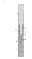
- FIG. 1 is a schematic sectional view showing a configuration of a joint structure 1 for a fiber reinforced resin and a metal according to this embodiment.
- the joint structure 1 includes a metal portion 2 constituted by a metallic material such as titanium, for example, and a resin portion 3 constituted by a fiber reinforced plastic such as CFRP, for example.
- An end portion 21 of the metal portion 2 includes a stepped structure that becomes thinner in steps in an end surface direction.
- the stepped structure is formed to become thinner in steps in a vertical direction so that a central portion of the metal portion 2 in a thickness direction thereof is thinnest.
- a large number of projections 22 are formed on an upper surface and a lower surface of the end portion 21 having the stepped structure.
- FIG. 2 is a schematic front view showing a configuration of the large number of projections 22.
- FIG. 2 shows a part of the large number of projections 22 constituted by five columns, for example.
- corresponding projections 22 in odd-numbered columns are disposed in positions having identical Y coordinates.
- the projections 22 in even-numbered columns are disposed in substantially intermediate locations between the projections 22 to the front and rear thereof in the odd-numbered columns.
- no projections 22 are disposed to the sides of any of the other projections 22 in an X direction, and as a result, spatial leeway is obtained.
- a plurality of grooves 23 is formed around each projection 22 to extend radially from a center of the projection 22.
- the plurality of grooves 23 is formed at substantially 45-degree angular intervals. As described above, more spatial leeway is available on the sides of the projections 22 in the X direction than in other directions, and therefore, of the plurality of grooves 23, the grooves 23 parallel to the X direction are formed to be longer than the other grooves 23.
- the projections 22 and the grooves 23 are formed by emitting a high energy density beam such as a laser beam or an electron beam onto a surface of the metal portion 2. More specifically, first, a high energy density beam is emitted onto the surface of the metal portion 2 rectilinearly from a planned central position of the projection 22 to a planned tip end position of the groove 23. As a result, the groove 23 is formed, while molten metal generated when forming the groove 23 is caused to project on an opposite side to an advancement direction of the high energy density beam, or in other words in the planned central position of the projection 22. By repeating this process for each groove 23, the projection 22 is formed at a predetermined height.
- a high energy density beam such as a laser beam or an electron beam
- the resin portion 3 is provided integrally with the metal portion 2 to cover the upper surface and the lower surface of the end portion 21 of the metal portion 2.
- the upper surface and the lower surface of the end portion 21 of the metal portion 2 constitute a joint surface of the metallic material, which serves as part of a joint surface between the fiber reinforced plastic and the metallic material according to the present invention.
- a plurality of sheets of fiber reinforced plastic is laminated successively onto the end portion 21 of the metal portion 2, which includes the stepped structure, in a prepreg condition obtained by impregnating reinforcing fibers with a matrix resin.
- the plurality of sheets of fiber reinforced plastic are divided into parts corresponding to respective steps on the end portion 21 of the metal portion 2.
- Thermosetting is then applied to the plurality of fiber reinforced plastics such that the metal portion 2 and the plurality of fiber reinforced plastics is adhered to each other and the respective fiber reinforced plastics are integrated to form the resin portion 3. Further, during the thermosetting, molten resin infiltrates the projections 22 and the grooves 23.
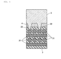
- FIG. 3 is a sectional view showing an enlargement of a rectangular S part of FIG. 1 .
- the height of the projection 22 is set so that the projections 22 contact reinforcing fibers (fibers) 31 in the resin portion 3.
- FIG. 3 shows a case in which the reinforcing fibers 31 of the resin portion 3 are laminated such that extension directions of the fibers are orthogonal to each other in the thickness direction.
- the reinforcing fibers 31 there are no limitations on the arrangement of the reinforcing fibers 31.
- the large number of projections 22 of a predetermined height are formed on the joint surface of the metal portion 2, and therefore a conductivity can be increased in comparison with a case where the projections 22 are not provided.
- the height of the projections 22 is set to be equal to or greater than a height enabling the projections 22 to contact the reinforcing fibers 31 constituting the resin portion 3, an equivalent conductivity to that of a fastener joint can be achieved.
- an equivalent conductivity to that of a fastener joint can be secured without the use of a fastening tool.
- the projections 22 must contact the reinforcing fibers 31. Therefore, when an adhesive layer 4 is interposed between the metal portion 2 and the resin portion 3, as shown in FIG. 4 , for example, the height of the projections 22 is preferably set in consideration of a thickness of the adhesive layer 4.
- the adhesive layer 4 interposed between the metal portion 2 and the resin portion 3 has a thickness of 0.2 to 0.25 mm
- a conductivity that is equivalent to or greater than that of a fastener joint can be obtained by forming the projections 22 at a height of at least 0.3 mm, taking into consideration not only the thickness of the adhesive layer 4 but also a thickness of resin on the outside of the reinforcing fibers 31.
- the projections 22 are formed by forming the grooves 23 using a high energy density beam such as a laser beam or an electron beam, whereby the resulting molten metal is caused to project.
- the height of the projection 22 increases together with a length of the groove 23 up to a saturation point, and therefore, to increase the height of the projection 22, an overall length of the plurality of grooves 23 must be increased.
- the projections 22 are disposed in the arrangement described above so that the grooves 23 parallel to the X direction are formed at a greater length than the other grooves 23.
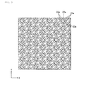
- the rectilinear grooves 23 are described as an example, but curved grooves may be formed instead.
- a plurality of grooves 23a extending radially from a center of a projection 22a is preferably caused to curve in an identical direction. More specifically, FIG. 5 shows a case in which respective tip ends of the plurality of grooves 23a curve in a clockwise direction from base ends thereof. Grooves curving in a counter-clockwise direction may of course also be used.
- the grooves 23a in this manner, the overall length of the plurality of grooves 23a can be increased while reducing a surface area occupied by the plurality of grooves 23. Accordingly, the projections 22a can be disposed at a higher density, and as a result, the conductivity between the resin portion 3 and the metal portion 2 can be increased efficiently.
- a composite material including conductive fibers, such as carbon fiber reinforced plastic, may be used as the applied fiber reinforced plastic.
- a Ti alloy, an Al alloy, an Mg alloy, and so on may be used as a material of the applied metallic material.
- any type of metallic material may be used.
- any type of thermosetting resin may be used as the applied resin.
Landscapes
- Engineering & Computer Science (AREA)
- Mechanical Engineering (AREA)
- Chemical & Material Sciences (AREA)
- Composite Materials (AREA)
- General Engineering & Computer Science (AREA)
- Physics & Mathematics (AREA)
- Thermal Sciences (AREA)
- Lining Or Joining Of Plastics Or The Like (AREA)
- Moulding By Coating Moulds (AREA)
Abstract
Description
- The present application claims priority from Japanese Patent Application No.
2012-123895, filed on May 31, 2012 - The present invention relates to a joint structure for a fiber reinforced resin and a metal.
- Fiber reinforced plastics (FRPs) are today used widely in structural members for aircraft, automobiles, ships, and general industrial instruments. For example, a known structural member is formed by impregnating a woven fabric, in which inorganic reinforcing fibers such as carbon fibers or glass fibers are arranged in a crisscross pattern and interwoven, with a resin such as epoxy resin, and then hardening the resin. In many cases, however, such structural members are not formed entirely from fiber reinforced plastics, and a metallic material must be applied partially thereto. In a known technique employed in such cases, as shown in
FIG. 6 , for example, a fastener joint is formed between a fiber reinforcedplastic 100 and ametallic material 101 using afastening tool 102 so that the fiber reinforcedplastic 100 and themetallic material 101 are firmly integrated. - When the
fastening tool 102 is attached, however, a current generated by lightning or electrification, for example, may cause spark discharge F in a projecting portion of thefastening tool 102, and therefore thefastening tool 102 is preferably not used. - In recent years, a technique of directly adhering a fiber reinforced plastic and a metallic material to ensure that the fiber reinforced plastic and the metallic material are joined with a high degree of strength has been proposed. In so doing, the
fastening tool 102 may be omitted, and as a result, a reduction in weight and so on can be achieved. Further, a technique of forming projections on a metallic material side joint surface serving as part of a joint surface between the fiber reinforced plastic and the metallic material in order to improve the strength of the joint between the fiber reinforced plastic and the metallic material has been developed (see Japanese Unexamined Patent Application Publication (Translation of PCT Application) No.2006-501070 - With the joint structure using the
fastening tool 102, however, an overall conductivity increases, and therefore a current generated by lightning or electrification can be expected to flow away smoothly, but when thefastening tool 102 is omitted, the conductivity inevitably decreases, and as a result, it may be impossible to remove the current smoothly. - The present invention has been designed in consideration of the circumstances described above, and an object thereof is to provide a joint structure for a fiber reinforced resin and a metal the structure being capable of securing an equivalent conductivity to that of a fastener joint without the use of a fastening tool.
- To achieve the object described above, an aspect of the present invention provides a joint structure for a fiber reinforced resin and a metal, in which respective end portions of a fiber reinforced plastic and a metallic material are joined to each other. A large number of projections having a height that enables the projections to contact fibers constituting the fiber reinforced plastic are formed on a joint surface of the metallic material serving as a part of a joint surface between the fiber reinforced plastic and the metallic material.
- Preferably, a plurality of grooves is formed around each of the projections to extend radially from a center of the projection, and the plurality of grooves curve in an identical direction.
-
-
FIG. 1 is a sectional view of a joint structure for a fiber reinforced plastic and a metal according to an embodiment of the present invention; -
FIG. 2 is a schematic front view showing a configuration of a large number of projections and grooves according to this embodiment; -
FIG. 3 is a sectional view showing an enlargement of a rectangular S part ofFIG. 1 ; -
FIG. 4 is a sectional view showing a modified example ofFIG. 3 ; -
FIG. 5 is a front view showing a modified example of the grooves shown inFIG. 2 ; and -
FIG. 6 is a sectional view showing a conventional joint structure for a fiber reinforced plastic and a metal. - An embodiment of the present invention will be described below with reference to the drawings. However, the present invention is not limited to the following embodiment.
-
FIG. 1 is a schematic sectional view showing a configuration of a joint structure 1 for a fiber reinforced resin and a metal according to this embodiment. As shown inFIG. 1 , the joint structure 1 includes ametal portion 2 constituted by a metallic material such as titanium, for example, and aresin portion 3 constituted by a fiber reinforced plastic such as CFRP, for example. - An
end portion 21 of themetal portion 2 includes a stepped structure that becomes thinner in steps in an end surface direction. In this embodiment, the stepped structure is formed to become thinner in steps in a vertical direction so that a central portion of themetal portion 2 in a thickness direction thereof is thinnest. A large number ofprojections 22 are formed on an upper surface and a lower surface of theend portion 21 having the stepped structure. -
FIG. 2 is a schematic front view showing a configuration of the large number ofprojections 22.FIG. 2 shows a part of the large number ofprojections 22 constituted by five columns, for example. Here,corresponding projections 22 in odd-numbered columns are disposed in positions having identical Y coordinates. Theprojections 22 in even-numbered columns, meanwhile, are disposed in substantially intermediate locations between theprojections 22 to the front and rear thereof in the odd-numbered columns. Thus, noprojections 22 are disposed to the sides of any of theother projections 22 in an X direction, and as a result, spatial leeway is obtained. - A plurality of
grooves 23 is formed around eachprojection 22 to extend radially from a center of theprojection 22. The plurality ofgrooves 23 is formed at substantially 45-degree angular intervals. As described above, more spatial leeway is available on the sides of theprojections 22 in the X direction than in other directions, and therefore, of the plurality ofgrooves 23, thegrooves 23 parallel to the X direction are formed to be longer than theother grooves 23. - Here, the
projections 22 and thegrooves 23 are formed by emitting a high energy density beam such as a laser beam or an electron beam onto a surface of themetal portion 2. More specifically, first, a high energy density beam is emitted onto the surface of themetal portion 2 rectilinearly from a planned central position of theprojection 22 to a planned tip end position of thegroove 23. As a result, thegroove 23 is formed, while molten metal generated when forming thegroove 23 is caused to project on an opposite side to an advancement direction of the high energy density beam, or in other words in the planned central position of theprojection 22. By repeating this process for eachgroove 23, theprojection 22 is formed at a predetermined height. - As shown in
FIG. 1 , theresin portion 3 is provided integrally with themetal portion 2 to cover the upper surface and the lower surface of theend portion 21 of themetal portion 2. The upper surface and the lower surface of theend portion 21 of themetal portion 2 constitute a joint surface of the metallic material, which serves as part of a joint surface between the fiber reinforced plastic and the metallic material according to the present invention. - To form the
resin portion 3, a plurality of sheets of fiber reinforced plastic is laminated successively onto theend portion 21 of themetal portion 2, which includes the stepped structure, in a prepreg condition obtained by impregnating reinforcing fibers with a matrix resin. For convenience, the plurality of sheets of fiber reinforced plastic are divided into parts corresponding to respective steps on theend portion 21 of themetal portion 2. Thermosetting is then applied to the plurality of fiber reinforced plastics such that themetal portion 2 and the plurality of fiber reinforced plastics is adhered to each other and the respective fiber reinforced plastics are integrated to form theresin portion 3. Further, during the thermosetting, molten resin infiltrates theprojections 22 and thegrooves 23. -
FIG. 3 is a sectional view showing an enlargement of a rectangular S part ofFIG. 1 . As shown inFIG. 3 , the height of theprojection 22 is set so that theprojections 22 contact reinforcing fibers (fibers) 31 in theresin portion 3. Note thatFIG. 3 shows a case in which the reinforcingfibers 31 of theresin portion 3 are laminated such that extension directions of the fibers are orthogonal to each other in the thickness direction. However, there are no limitations on the arrangement of the reinforcingfibers 31. - According to this embodiment, as described above, the large number of
projections 22 of a predetermined height are formed on the joint surface of themetal portion 2, and therefore a conductivity can be increased in comparison with a case where theprojections 22 are not provided. In particular, when the height of theprojections 22 is set to be equal to or greater than a height enabling theprojections 22 to contact the reinforcingfibers 31 constituting theresin portion 3, an equivalent conductivity to that of a fastener joint can be achieved. Hence, an equivalent conductivity to that of a fastener joint can be secured without the use of a fastening tool. - As described above, to obtain at least an equivalent conductivity to that of a fastener joint, the
projections 22 must contact the reinforcingfibers 31. Therefore, when anadhesive layer 4 is interposed between themetal portion 2 and theresin portion 3, as shown inFIG. 4 , for example, the height of theprojections 22 is preferably set in consideration of a thickness of theadhesive layer 4. For example, when theadhesive layer 4 interposed between themetal portion 2 and theresin portion 3 has a thickness of 0.2 to 0.25 mm, a conductivity that is equivalent to or greater than that of a fastener joint can be obtained by forming theprojections 22 at a height of at least 0.3 mm, taking into consideration not only the thickness of theadhesive layer 4 but also a thickness of resin on the outside of the reinforcingfibers 31. - As described above, the
projections 22 are formed by forming thegrooves 23 using a high energy density beam such as a laser beam or an electron beam, whereby the resulting molten metal is caused to project. The height of theprojection 22 increases together with a length of thegroove 23 up to a saturation point, and therefore, to increase the height of theprojection 22, an overall length of the plurality ofgrooves 23 must be increased. Hence, in this embodiment, theprojections 22 are disposed in the arrangement described above so that thegrooves 23 parallel to the X direction are formed at a greater length than theother grooves 23. - Note that the present invention is not limited to the above embodiment and may be modified appropriately.
- For example, in the above embodiment, the
rectilinear grooves 23 are described as an example, but curved grooves may be formed instead. As shown inFIG. 5 , for example, a plurality ofgrooves 23a extending radially from a center of aprojection 22a is preferably caused to curve in an identical direction. More specifically,FIG. 5 shows a case in which respective tip ends of the plurality ofgrooves 23a curve in a clockwise direction from base ends thereof. Grooves curving in a counter-clockwise direction may of course also be used. By forming thegrooves 23a in this manner, the overall length of the plurality ofgrooves 23a can be increased while reducing a surface area occupied by the plurality ofgrooves 23. Accordingly, theprojections 22a can be disposed at a higher density, and as a result, the conductivity between theresin portion 3 and themetal portion 2 can be increased efficiently. - A composite material including conductive fibers, such as carbon fiber reinforced plastic, may be used as the applied fiber reinforced plastic.
- A Ti alloy, an Al alloy, an Mg alloy, and so on may be used as a material of the applied metallic material. However, any type of metallic material may be used. Further, any type of thermosetting resin may be used as the applied resin.
Claims (2)
- A joint structure for a fiber reinforced resin and a metal, in which respective end portions of a fiber reinforced plastic and a metallic material are joined to each other,
wherein a large number of projections having a height that enables the projections to contact fibers constituting the fiber reinforced plastic are formed on a joint surface of the metallic material serving as a part of a joint surface between the fiber reinforced plastic and the metallic material. - The joint structure for a fiber reinforced resin and a metal according to claim 1, wherein a plurality of grooves is formed around each of the projections to extend radially from a center of the projection, and
the plurality of grooves curves in an identical direction.
Applications Claiming Priority (1)
| Application Number | Priority Date | Filing Date | Title |
|---|---|---|---|
| JP2012123895A JP5961451B2 (en) | 2012-05-31 | 2012-05-31 | Bonding structure of fiber reinforced resin and metal |
Publications (3)
| Publication Number | Publication Date |
|---|---|
| EP2669077A2 true EP2669077A2 (en) | 2013-12-04 |
| EP2669077A3 EP2669077A3 (en) | 2016-03-16 |
| EP2669077B1 EP2669077B1 (en) | 2018-06-27 |
Family
ID=48430448
Family Applications (1)
| Application Number | Title | Priority Date | Filing Date |
|---|---|---|---|
| EP13165301.6A Active EP2669077B1 (en) | 2012-05-31 | 2013-04-25 | Joint structure for fiber reinforced resin and metal |
Country Status (3)
| Country | Link |
|---|---|
| US (1) | US9279436B2 (en) |
| EP (1) | EP2669077B1 (en) |
| JP (1) | JP5961451B2 (en) |
Cited By (5)
| Publication number | Priority date | Publication date | Assignee | Title |
|---|---|---|---|---|
| FR3021899A1 (en) * | 2014-06-10 | 2015-12-11 | Inst Rech Technologique Jules Verne | METHOD AND DEVICE FOR METAL-COMPOSITE ASSEMBLY |
| JP2016043578A (en) * | 2014-08-22 | 2016-04-04 | トヨタ自動車株式会社 | Part-to-part connecting structure and part-to-part connecting method |
| WO2017060646A1 (en) * | 2015-10-07 | 2017-04-13 | Centre Technique Des Industries Mecaniques | Method for securing a composite element with a rigid element |
| EP3403807A1 (en) * | 2017-05-18 | 2018-11-21 | BAE SYSTEMS plc | Fastenerless structural assembly |
| WO2018211233A1 (en) * | 2017-05-18 | 2018-11-22 | Bae Systems Plc | Fastenerless structural assembly |
Families Citing this family (13)
| Publication number | Priority date | Publication date | Assignee | Title |
|---|---|---|---|---|
| EP3389917B1 (en) * | 2015-12-17 | 2021-09-22 | SHPP Global Technologies B.V. | Methods of making plastic-metal junctions via laser |
| US10940478B2 (en) | 2016-01-22 | 2021-03-09 | University Of Washington | Contact-line-driven microfluidic devices and methods |
| KR101807039B1 (en) * | 2016-04-28 | 2017-12-08 | 현대자동차 주식회사 | Composites having insert steel for welding |
| JP6789047B2 (en) * | 2016-09-23 | 2020-11-25 | 矢崎総業株式会社 | Vehicle ground structure |
| US20190145446A1 (en) * | 2017-11-10 | 2019-05-16 | Ford Global Technologies, Llc | Integrated fixture retention mechanism |
| JP7193377B2 (en) * | 2019-02-25 | 2022-12-20 | 三菱重工業株式会社 | Joining material |
| DE102019106260A1 (en) * | 2019-03-12 | 2020-09-17 | HELLA GmbH & Co. KGaA | Process for the production of a joint between a plastic component with a lighting technology and a metal component |
| DE102019106284A1 (en) * | 2019-03-12 | 2020-09-17 | HELLA GmbH & Co. KGaA | Method for producing a joint between a structural component made of a plastic and a metal component |
| CN111844815B (en) * | 2020-07-15 | 2021-11-02 | 哈尔滨工业大学 | A connection method of steel material and carbon fiber braid |
| EP4026972B1 (en) | 2021-01-06 | 2024-10-09 | Minebea AccessSolutions Italia S.p.A. | Electronic vehicle handle assembly including a mechanical switch |
| JP7537333B2 (en) * | 2021-03-25 | 2024-08-21 | トヨタ紡織株式会社 | Composite materials, car seats, car parts |
| JP7790048B2 (en) * | 2021-08-18 | 2025-12-23 | 住友ゴム工業株式会社 | Golf club head |
| CN113752668B (en) * | 2021-09-07 | 2023-06-13 | 河北工业大学 | Preparation method of fiber metal laminate with leaf vein bionic negative poisson ratio structure |
Citations (1)
| Publication number | Priority date | Publication date | Assignee | Title |
|---|---|---|---|---|
| JP2006501070A (en) | 2002-09-30 | 2006-01-12 | ザ ウェルディング インスティテュート | Changing the structure of the workpiece |
Family Cites Families (13)
| Publication number | Priority date | Publication date | Assignee | Title |
|---|---|---|---|---|
| US4678455A (en) * | 1981-07-07 | 1987-07-07 | Dayco Products, Inc. | Method of making a fiber-loaded polymeric sheet |
| JPS6189029A (en) * | 1984-10-08 | 1986-05-07 | Mitsubishi Heavy Ind Ltd | Method of joining cfrp and metal |
| JP3433850B2 (en) * | 1994-10-04 | 2003-08-04 | 東レ株式会社 | FRP cylinder and manufacturing method thereof |
| US6176959B1 (en) * | 1999-02-08 | 2001-01-23 | Vought Aircraft Industries, Inc. | Method for microtexturizing and bonding two surfaces |
| DE50007631D1 (en) * | 1999-03-31 | 2004-10-07 | Alcan Tech & Man Ag | Plastic component with inserts |
| US6660129B1 (en) * | 2000-10-24 | 2003-12-09 | The Procter & Gamble Company | Fibrous structure having increased surface area |
| US7802799B1 (en) * | 2006-09-18 | 2010-09-28 | The United States Of America As Represented By The Administrator Of The National Aeronautics And Space Administration | Method of joining metallic and composite components |
| GB0704753D0 (en) * | 2007-03-13 | 2007-04-18 | Airbus Uk Ltd | Preparation of a component for use in a joint |
| GB0905134D0 (en) * | 2009-03-25 | 2009-05-06 | Airbus Uk Ltd | Height tailoring of interfacing projections |
| GB0905133D0 (en) * | 2009-03-25 | 2009-05-06 | Airbus Uk Ltd | Orientation of interfacing projections |
| DE102009017776B4 (en) * | 2009-04-20 | 2022-03-24 | Airbus Defence and Space GmbH | Process for connecting a fiber composite material to a metallic component and its use |
| WO2011045895A1 (en) * | 2009-10-16 | 2011-04-21 | アイシン精機株式会社 | Composite molded article |
| GB2479776B (en) * | 2010-04-22 | 2012-08-29 | Eads Uk Ltd | Testing joints between composite and metal parts |
-
2012
- 2012-05-31 JP JP2012123895A patent/JP5961451B2/en active Active
-
2013
- 2013-04-25 EP EP13165301.6A patent/EP2669077B1/en active Active
- 2013-05-06 US US13/888,228 patent/US9279436B2/en active Active
Patent Citations (1)
| Publication number | Priority date | Publication date | Assignee | Title |
|---|---|---|---|---|
| JP2006501070A (en) | 2002-09-30 | 2006-01-12 | ザ ウェルディング インスティテュート | Changing the structure of the workpiece |
Cited By (8)
| Publication number | Priority date | Publication date | Assignee | Title |
|---|---|---|---|---|
| FR3021899A1 (en) * | 2014-06-10 | 2015-12-11 | Inst Rech Technologique Jules Verne | METHOD AND DEVICE FOR METAL-COMPOSITE ASSEMBLY |
| WO2015189237A1 (en) * | 2014-06-10 | 2015-12-17 | Institut De Recherche Technologique Jules Verne | Metal/composite assembly method and device |
| US10513067B2 (en) | 2014-06-10 | 2019-12-24 | Institut De Recherche Technologique Jules Verne | Metal/composite assembly method |
| JP2016043578A (en) * | 2014-08-22 | 2016-04-04 | トヨタ自動車株式会社 | Part-to-part connecting structure and part-to-part connecting method |
| WO2017060646A1 (en) * | 2015-10-07 | 2017-04-13 | Centre Technique Des Industries Mecaniques | Method for securing a composite element with a rigid element |
| FR3042196A1 (en) * | 2015-10-07 | 2017-04-14 | Centre Technique Des Ind Mec | METHOD FOR SOLIDARIZING A COMPOSITE ELEMENT AND A RIGID ELEMENT |
| EP3403807A1 (en) * | 2017-05-18 | 2018-11-21 | BAE SYSTEMS plc | Fastenerless structural assembly |
| WO2018211233A1 (en) * | 2017-05-18 | 2018-11-22 | Bae Systems Plc | Fastenerless structural assembly |
Also Published As
| Publication number | Publication date |
|---|---|
| JP2013248769A (en) | 2013-12-12 |
| US20130322962A1 (en) | 2013-12-05 |
| EP2669077A3 (en) | 2016-03-16 |
| EP2669077B1 (en) | 2018-06-27 |
| US9279436B2 (en) | 2016-03-08 |
| JP5961451B2 (en) | 2016-08-02 |
Similar Documents
| Publication | Publication Date | Title |
|---|---|---|
| US9279436B2 (en) | Joint structure for fiber reinforced resin and metal | |
| US7182291B2 (en) | Integrated aircraft structural floor | |
| US8795804B2 (en) | Joint structure for fiber reinforced resin and metal, and joining method for fiber reinforced resin and metal | |
| US20180212212A1 (en) | Battery module and end plate of the battery module | |
| US9347221B2 (en) | Lightweight structural panel | |
| CA2923152C (en) | Joint, and aircraft structure | |
| US20160244140A1 (en) | Joint, and aircraft structure | |
| US20200095873A1 (en) | Composite blade and method of manufacturing composite blade | |
| EP2636509B1 (en) | Joint structure for fiber reinforced resin and metal, and joining method for fiber reinforced resin and metal | |
| JP6278776B2 (en) | Sandwich panel and its manufacturing method | |
| JP6961984B2 (en) | Column structure | |
| JP5045285B2 (en) | Fabrication method of fiber reinforced resin face material | |
| JP4757650B2 (en) | Pantograph cover | |
| JP6683293B2 (en) | Automotive T-joint structure | |
| JP2017066700A (en) | Girder structure | |
| CN104981969A (en) | Movable element and linear motor provided with same | |
| JP2002190612A (en) | Solar array panel and method of manufacturing the same | |
| CN109955487A (en) | Manufacturing method of composite components | |
| JP2019167063A (en) | Vehicle wheel | |
| JP2021169209A (en) | Composite material having reinforced access opening | |
| CN108297493B (en) | Heat and mechanical shock resistant laminated sheet metal assembly | |
| CN217216989U (en) | Flexible circuit board | |
| CN115151433A (en) | Reinforcing structure of panel parts | |
| KR102131777B1 (en) | Composite plate and method joining for of the same | |
| JP2020131915A (en) | Connection member |
Legal Events
| Date | Code | Title | Description |
|---|---|---|---|
| PUAI | Public reference made under article 153(3) epc to a published international application that has entered the european phase |
Free format text: ORIGINAL CODE: 0009012 |
|
| AK | Designated contracting states |
Kind code of ref document: A2 Designated state(s): AL AT BE BG CH CY CZ DE DK EE ES FI FR GB GR HR HU IE IS IT LI LT LU LV MC MK MT NL NO PL PT RO RS SE SI SK SM TR |
|
| AX | Request for extension of the european patent |
Extension state: BA ME |
|
| RAP1 | Party data changed (applicant data changed or rights of an application transferred) |
Owner name: FUJI JUKOGYO KABUSHIKI KAISHA |
|
| PUAL | Search report despatched |
Free format text: ORIGINAL CODE: 0009013 |
|
| AK | Designated contracting states |
Kind code of ref document: A3 Designated state(s): AL AT BE BG CH CY CZ DE DK EE ES FI FR GB GR HR HU IE IS IT LI LT LU LV MC MK MT NL NO PL PT RO RS SE SI SK SM TR |
|
| AX | Request for extension of the european patent |
Extension state: BA ME |
|
| RIC1 | Information provided on ipc code assigned before grant |
Ipc: B29K 705/00 20060101ALN20160209BHEP Ipc: B29C 65/48 20060101ALI20160209BHEP Ipc: B29C 65/56 20060101ALI20160209BHEP Ipc: B29K 105/08 20060101ALN20160209BHEP Ipc: B29C 70/76 20060101AFI20160209BHEP Ipc: B29C 70/30 20060101ALI20160209BHEP Ipc: B29C 65/02 20060101ALI20160209BHEP |
|
| 17P | Request for examination filed |
Effective date: 20160727 |
|
| RBV | Designated contracting states (corrected) |
Designated state(s): AL AT BE BG CH CY CZ DE DK EE ES FI FR GB GR HR HU IE IS IT LI LT LU LV MC MK MT NL NO PL PT RO RS SE SI SK SM TR |
|
| RAP1 | Party data changed (applicant data changed or rights of an application transferred) |
Owner name: SUBARU CORPORATION |
|
| GRAP | Despatch of communication of intention to grant a patent |
Free format text: ORIGINAL CODE: EPIDOSNIGR1 |
|
| STAA | Information on the status of an ep patent application or granted ep patent |
Free format text: STATUS: GRANT OF PATENT IS INTENDED |
|
| RIC1 | Information provided on ipc code assigned before grant |
Ipc: B29K 105/08 20060101ALI20171204BHEP Ipc: B29C 70/76 20060101AFI20171204BHEP Ipc: F16B 3/00 20060101ALI20171204BHEP Ipc: B29C 65/48 20060101ALI20171204BHEP Ipc: B29C 65/56 20060101ALI20171204BHEP Ipc: B29C 65/72 20060101ALI20171204BHEP Ipc: B29L 31/30 20060101ALI20171204BHEP Ipc: B29C 70/30 20060101ALI20171204BHEP Ipc: B29C 37/00 20060101ALI20171204BHEP Ipc: B29C 65/02 20060101ALI20171204BHEP Ipc: B29C 65/00 20060101ALI20171204BHEP |
|
| INTG | Intention to grant announced |
Effective date: 20180108 |
|
| GRAS | Grant fee paid |
Free format text: ORIGINAL CODE: EPIDOSNIGR3 |
|
| GRAA | (expected) grant |
Free format text: ORIGINAL CODE: 0009210 |
|
| STAA | Information on the status of an ep patent application or granted ep patent |
Free format text: STATUS: THE PATENT HAS BEEN GRANTED |
|
| AK | Designated contracting states |
Kind code of ref document: B1 Designated state(s): AL AT BE BG CH CY CZ DE DK EE ES FI FR GB GR HR HU IE IS IT LI LT LU LV MC MK MT NL NO PL PT RO RS SE SI SK SM TR |
|
| REG | Reference to a national code |
Ref country code: GB Ref legal event code: FG4D |
|
| REG | Reference to a national code |
Ref country code: AT Ref legal event code: REF Ref document number: 1011927 Country of ref document: AT Kind code of ref document: T Effective date: 20180715 |
|
| REG | Reference to a national code |
Ref country code: IE Ref legal event code: FG4D |
|
| REG | Reference to a national code |
Ref country code: DE Ref legal event code: R096 Ref document number: 602013039324 Country of ref document: DE |
|
| PG25 | Lapsed in a contracting state [announced via postgrant information from national office to epo] |
Ref country code: SE Free format text: LAPSE BECAUSE OF FAILURE TO SUBMIT A TRANSLATION OF THE DESCRIPTION OR TO PAY THE FEE WITHIN THE PRESCRIBED TIME-LIMIT Effective date: 20180627 Ref country code: FI Free format text: LAPSE BECAUSE OF FAILURE TO SUBMIT A TRANSLATION OF THE DESCRIPTION OR TO PAY THE FEE WITHIN THE PRESCRIBED TIME-LIMIT Effective date: 20180627 Ref country code: BG Free format text: LAPSE BECAUSE OF FAILURE TO SUBMIT A TRANSLATION OF THE DESCRIPTION OR TO PAY THE FEE WITHIN THE PRESCRIBED TIME-LIMIT Effective date: 20180927 Ref country code: LT Free format text: LAPSE BECAUSE OF FAILURE TO SUBMIT A TRANSLATION OF THE DESCRIPTION OR TO PAY THE FEE WITHIN THE PRESCRIBED TIME-LIMIT Effective date: 20180627 Ref country code: NO Free format text: LAPSE BECAUSE OF FAILURE TO SUBMIT A TRANSLATION OF THE DESCRIPTION OR TO PAY THE FEE WITHIN THE PRESCRIBED TIME-LIMIT Effective date: 20180927 |
|
| REG | Reference to a national code |
Ref country code: NL Ref legal event code: MP Effective date: 20180627 |
|
| REG | Reference to a national code |
Ref country code: LT Ref legal event code: MG4D |
|
| PG25 | Lapsed in a contracting state [announced via postgrant information from national office to epo] |
Ref country code: GR Free format text: LAPSE BECAUSE OF FAILURE TO SUBMIT A TRANSLATION OF THE DESCRIPTION OR TO PAY THE FEE WITHIN THE PRESCRIBED TIME-LIMIT Effective date: 20180928 Ref country code: HR Free format text: LAPSE BECAUSE OF FAILURE TO SUBMIT A TRANSLATION OF THE DESCRIPTION OR TO PAY THE FEE WITHIN THE PRESCRIBED TIME-LIMIT Effective date: 20180627 Ref country code: LV Free format text: LAPSE BECAUSE OF FAILURE TO SUBMIT A TRANSLATION OF THE DESCRIPTION OR TO PAY THE FEE WITHIN THE PRESCRIBED TIME-LIMIT Effective date: 20180627 Ref country code: RS Free format text: LAPSE BECAUSE OF FAILURE TO SUBMIT A TRANSLATION OF THE DESCRIPTION OR TO PAY THE FEE WITHIN THE PRESCRIBED TIME-LIMIT Effective date: 20180627 |
|
| REG | Reference to a national code |
Ref country code: AT Ref legal event code: MK05 Ref document number: 1011927 Country of ref document: AT Kind code of ref document: T Effective date: 20180627 |
|
| PG25 | Lapsed in a contracting state [announced via postgrant information from national office to epo] |
Ref country code: NL Free format text: LAPSE BECAUSE OF FAILURE TO SUBMIT A TRANSLATION OF THE DESCRIPTION OR TO PAY THE FEE WITHIN THE PRESCRIBED TIME-LIMIT Effective date: 20180627 |
|
| PG25 | Lapsed in a contracting state [announced via postgrant information from national office to epo] |
Ref country code: RO Free format text: LAPSE BECAUSE OF FAILURE TO SUBMIT A TRANSLATION OF THE DESCRIPTION OR TO PAY THE FEE WITHIN THE PRESCRIBED TIME-LIMIT Effective date: 20180627 Ref country code: CZ Free format text: LAPSE BECAUSE OF FAILURE TO SUBMIT A TRANSLATION OF THE DESCRIPTION OR TO PAY THE FEE WITHIN THE PRESCRIBED TIME-LIMIT Effective date: 20180627 Ref country code: AT Free format text: LAPSE BECAUSE OF FAILURE TO SUBMIT A TRANSLATION OF THE DESCRIPTION OR TO PAY THE FEE WITHIN THE PRESCRIBED TIME-LIMIT Effective date: 20180627 Ref country code: EE Free format text: LAPSE BECAUSE OF FAILURE TO SUBMIT A TRANSLATION OF THE DESCRIPTION OR TO PAY THE FEE WITHIN THE PRESCRIBED TIME-LIMIT Effective date: 20180627 Ref country code: PL Free format text: LAPSE BECAUSE OF FAILURE TO SUBMIT A TRANSLATION OF THE DESCRIPTION OR TO PAY THE FEE WITHIN THE PRESCRIBED TIME-LIMIT Effective date: 20180627 Ref country code: IS Free format text: LAPSE BECAUSE OF FAILURE TO SUBMIT A TRANSLATION OF THE DESCRIPTION OR TO PAY THE FEE WITHIN THE PRESCRIBED TIME-LIMIT Effective date: 20181027 Ref country code: SK Free format text: LAPSE BECAUSE OF FAILURE TO SUBMIT A TRANSLATION OF THE DESCRIPTION OR TO PAY THE FEE WITHIN THE PRESCRIBED TIME-LIMIT Effective date: 20180627 |
|
| PG25 | Lapsed in a contracting state [announced via postgrant information from national office to epo] |
Ref country code: IT Free format text: LAPSE BECAUSE OF FAILURE TO SUBMIT A TRANSLATION OF THE DESCRIPTION OR TO PAY THE FEE WITHIN THE PRESCRIBED TIME-LIMIT Effective date: 20180627 Ref country code: SM Free format text: LAPSE BECAUSE OF FAILURE TO SUBMIT A TRANSLATION OF THE DESCRIPTION OR TO PAY THE FEE WITHIN THE PRESCRIBED TIME-LIMIT Effective date: 20180627 Ref country code: ES Free format text: LAPSE BECAUSE OF FAILURE TO SUBMIT A TRANSLATION OF THE DESCRIPTION OR TO PAY THE FEE WITHIN THE PRESCRIBED TIME-LIMIT Effective date: 20180627 |
|
| REG | Reference to a national code |
Ref country code: DE Ref legal event code: R097 Ref document number: 602013039324 Country of ref document: DE |
|
| PLBE | No opposition filed within time limit |
Free format text: ORIGINAL CODE: 0009261 |
|
| STAA | Information on the status of an ep patent application or granted ep patent |
Free format text: STATUS: NO OPPOSITION FILED WITHIN TIME LIMIT |
|
| PG25 | Lapsed in a contracting state [announced via postgrant information from national office to epo] |
Ref country code: DK Free format text: LAPSE BECAUSE OF FAILURE TO SUBMIT A TRANSLATION OF THE DESCRIPTION OR TO PAY THE FEE WITHIN THE PRESCRIBED TIME-LIMIT Effective date: 20180627 |
|
| 26N | No opposition filed |
Effective date: 20190328 |
|
| PG25 | Lapsed in a contracting state [announced via postgrant information from national office to epo] |
Ref country code: SI Free format text: LAPSE BECAUSE OF FAILURE TO SUBMIT A TRANSLATION OF THE DESCRIPTION OR TO PAY THE FEE WITHIN THE PRESCRIBED TIME-LIMIT Effective date: 20180627 |
|
| PG25 | Lapsed in a contracting state [announced via postgrant information from national office to epo] |
Ref country code: AL Free format text: LAPSE BECAUSE OF FAILURE TO SUBMIT A TRANSLATION OF THE DESCRIPTION OR TO PAY THE FEE WITHIN THE PRESCRIBED TIME-LIMIT Effective date: 20180627 |
|
| REG | Reference to a national code |
Ref country code: CH Ref legal event code: PL |
|
| REG | Reference to a national code |
Ref country code: BE Ref legal event code: MM Effective date: 20190430 |
|
| GBPC | Gb: european patent ceased through non-payment of renewal fee |
Effective date: 20190425 |
|
| PG25 | Lapsed in a contracting state [announced via postgrant information from national office to epo] |
Ref country code: LU Free format text: LAPSE BECAUSE OF NON-PAYMENT OF DUE FEES Effective date: 20190425 Ref country code: MC Free format text: LAPSE BECAUSE OF FAILURE TO SUBMIT A TRANSLATION OF THE DESCRIPTION OR TO PAY THE FEE WITHIN THE PRESCRIBED TIME-LIMIT Effective date: 20180627 |
|
| PG25 | Lapsed in a contracting state [announced via postgrant information from national office to epo] |
Ref country code: CH Free format text: LAPSE BECAUSE OF NON-PAYMENT OF DUE FEES Effective date: 20190430 Ref country code: LI Free format text: LAPSE BECAUSE OF NON-PAYMENT OF DUE FEES Effective date: 20190430 Ref country code: GB Free format text: LAPSE BECAUSE OF NON-PAYMENT OF DUE FEES Effective date: 20190425 |
|
| PG25 | Lapsed in a contracting state [announced via postgrant information from national office to epo] |
Ref country code: BE Free format text: LAPSE BECAUSE OF NON-PAYMENT OF DUE FEES Effective date: 20190430 |
|
| PG25 | Lapsed in a contracting state [announced via postgrant information from national office to epo] |
Ref country code: TR Free format text: LAPSE BECAUSE OF FAILURE TO SUBMIT A TRANSLATION OF THE DESCRIPTION OR TO PAY THE FEE WITHIN THE PRESCRIBED TIME-LIMIT Effective date: 20180627 |
|
| PG25 | Lapsed in a contracting state [announced via postgrant information from national office to epo] |
Ref country code: IE Free format text: LAPSE BECAUSE OF NON-PAYMENT OF DUE FEES Effective date: 20190425 |
|
| PG25 | Lapsed in a contracting state [announced via postgrant information from national office to epo] |
Ref country code: PT Free format text: LAPSE BECAUSE OF FAILURE TO SUBMIT A TRANSLATION OF THE DESCRIPTION OR TO PAY THE FEE WITHIN THE PRESCRIBED TIME-LIMIT Effective date: 20181029 |
|
| PG25 | Lapsed in a contracting state [announced via postgrant information from national office to epo] |
Ref country code: CY Free format text: LAPSE BECAUSE OF FAILURE TO SUBMIT A TRANSLATION OF THE DESCRIPTION OR TO PAY THE FEE WITHIN THE PRESCRIBED TIME-LIMIT Effective date: 20180627 |
|
| PG25 | Lapsed in a contracting state [announced via postgrant information from national office to epo] |
Ref country code: HU Free format text: LAPSE BECAUSE OF FAILURE TO SUBMIT A TRANSLATION OF THE DESCRIPTION OR TO PAY THE FEE WITHIN THE PRESCRIBED TIME-LIMIT; INVALID AB INITIO Effective date: 20130425 Ref country code: MT Free format text: LAPSE BECAUSE OF FAILURE TO SUBMIT A TRANSLATION OF THE DESCRIPTION OR TO PAY THE FEE WITHIN THE PRESCRIBED TIME-LIMIT Effective date: 20180627 |
|
| PG25 | Lapsed in a contracting state [announced via postgrant information from national office to epo] |
Ref country code: MK Free format text: LAPSE BECAUSE OF FAILURE TO SUBMIT A TRANSLATION OF THE DESCRIPTION OR TO PAY THE FEE WITHIN THE PRESCRIBED TIME-LIMIT Effective date: 20180627 |
|
| PGFP | Annual fee paid to national office [announced via postgrant information from national office to epo] |
Ref country code: DE Payment date: 20250422 Year of fee payment: 13 |
|
| PGFP | Annual fee paid to national office [announced via postgrant information from national office to epo] |
Ref country code: FR Payment date: 20250425 Year of fee payment: 13 |