JP7193377B2 - Joining material - Google Patents
Joining material Download PDFInfo
- Publication number
- JP7193377B2 JP7193377B2 JP2019031265A JP2019031265A JP7193377B2 JP 7193377 B2 JP7193377 B2 JP 7193377B2 JP 2019031265 A JP2019031265 A JP 2019031265A JP 2019031265 A JP2019031265 A JP 2019031265A JP 7193377 B2 JP7193377 B2 JP 7193377B2
- Authority
- JP
- Japan
- Prior art keywords
- engaging portion
- base
- resin
- extending
- layer
- Prior art date
- Legal status (The legal status is an assumption and is not a legal conclusion. Google has not performed a legal analysis and makes no representation as to the accuracy of the status listed.)
- Active
Links
Images


Classifications
-
- B—PERFORMING OPERATIONS; TRANSPORTING
- B29—WORKING OF PLASTICS; WORKING OF SUBSTANCES IN A PLASTIC STATE IN GENERAL
- B29C—SHAPING OR JOINING OF PLASTICS; SHAPING OF MATERIAL IN A PLASTIC STATE, NOT OTHERWISE PROVIDED FOR; AFTER-TREATMENT OF THE SHAPED PRODUCTS, e.g. REPAIRING
- B29C45/00—Injection moulding, i.e. forcing the required volume of moulding material through a nozzle into a closed mould; Apparatus therefor
- B29C45/14—Injection moulding, i.e. forcing the required volume of moulding material through a nozzle into a closed mould; Apparatus therefor incorporating preformed parts or layers, e.g. injection moulding around inserts or for coating articles
- B29C45/14311—Injection moulding, i.e. forcing the required volume of moulding material through a nozzle into a closed mould; Apparatus therefor incorporating preformed parts or layers, e.g. injection moulding around inserts or for coating articles using means for bonding the coating to the articles
-
- B—PERFORMING OPERATIONS; TRANSPORTING
- B22—CASTING; POWDER METALLURGY
- B22F—WORKING METALLIC POWDER; MANUFACTURE OF ARTICLES FROM METALLIC POWDER; MAKING METALLIC POWDER; APPARATUS OR DEVICES SPECIALLY ADAPTED FOR METALLIC POWDER
- B22F3/00—Manufacture of workpieces or articles from metallic powder characterised by the manner of compacting or sintering; Apparatus specially adapted therefor ; Presses and furnaces
- B22F3/10—Sintering only
- B22F3/11—Making porous workpieces or articles
- B22F3/1103—Making porous workpieces or articles with particular physical characteristics
- B22F3/1115—Making porous workpieces or articles with particular physical characteristics comprising complex forms, e.g. honeycombs
-
- B—PERFORMING OPERATIONS; TRANSPORTING
- B22—CASTING; POWDER METALLURGY
- B22F—WORKING METALLIC POWDER; MANUFACTURE OF ARTICLES FROM METALLIC POWDER; MAKING METALLIC POWDER; APPARATUS OR DEVICES SPECIALLY ADAPTED FOR METALLIC POWDER
- B22F7/00—Manufacture of composite layers, workpieces, or articles, comprising metallic powder, by sintering the powder, with or without compacting wherein at least one part is obtained by sintering or compression
- B22F7/06—Manufacture of composite layers, workpieces, or articles, comprising metallic powder, by sintering the powder, with or without compacting wherein at least one part is obtained by sintering or compression of composite workpieces or articles from parts, e.g. to form tipped tools
- B22F7/08—Manufacture of composite layers, workpieces, or articles, comprising metallic powder, by sintering the powder, with or without compacting wherein at least one part is obtained by sintering or compression of composite workpieces or articles from parts, e.g. to form tipped tools with one or more parts not made from powder
-
- B—PERFORMING OPERATIONS; TRANSPORTING
- B29—WORKING OF PLASTICS; WORKING OF SUBSTANCES IN A PLASTIC STATE IN GENERAL
- B29C—SHAPING OR JOINING OF PLASTICS; SHAPING OF MATERIAL IN A PLASTIC STATE, NOT OTHERWISE PROVIDED FOR; AFTER-TREATMENT OF THE SHAPED PRODUCTS, e.g. REPAIRING
- B29C45/00—Injection moulding, i.e. forcing the required volume of moulding material through a nozzle into a closed mould; Apparatus therefor
- B29C45/14—Injection moulding, i.e. forcing the required volume of moulding material through a nozzle into a closed mould; Apparatus therefor incorporating preformed parts or layers, e.g. injection moulding around inserts or for coating articles
- B29C45/14467—Joining articles or parts of a single article
-
- B—PERFORMING OPERATIONS; TRANSPORTING
- B33—ADDITIVE MANUFACTURING TECHNOLOGY
- B33Y—ADDITIVE MANUFACTURING, i.e. MANUFACTURING OF THREE-DIMENSIONAL [3-D] OBJECTS BY ADDITIVE DEPOSITION, ADDITIVE AGGLOMERATION OR ADDITIVE LAYERING, e.g. BY 3-D PRINTING, STEREOLITHOGRAPHY OR SELECTIVE LASER SINTERING
- B33Y80/00—Products made by additive manufacturing
-
- B—PERFORMING OPERATIONS; TRANSPORTING
- B22—CASTING; POWDER METALLURGY
- B22F—WORKING METALLIC POWDER; MANUFACTURE OF ARTICLES FROM METALLIC POWDER; MAKING METALLIC POWDER; APPARATUS OR DEVICES SPECIALLY ADAPTED FOR METALLIC POWDER
- B22F10/00—Additive manufacturing of workpieces or articles from metallic powder
- B22F10/10—Formation of a green body
- B22F10/14—Formation of a green body by jetting of binder onto a bed of metal powder
-
- B—PERFORMING OPERATIONS; TRANSPORTING
- B22—CASTING; POWDER METALLURGY
- B22F—WORKING METALLIC POWDER; MANUFACTURE OF ARTICLES FROM METALLIC POWDER; MAKING METALLIC POWDER; APPARATUS OR DEVICES SPECIALLY ADAPTED FOR METALLIC POWDER
- B22F10/00—Additive manufacturing of workpieces or articles from metallic powder
- B22F10/20—Direct sintering or melting
- B22F10/22—Direct deposition of molten metal
-
- B—PERFORMING OPERATIONS; TRANSPORTING
- B22—CASTING; POWDER METALLURGY
- B22F—WORKING METALLIC POWDER; MANUFACTURE OF ARTICLES FROM METALLIC POWDER; MAKING METALLIC POWDER; APPARATUS OR DEVICES SPECIALLY ADAPTED FOR METALLIC POWDER
- B22F10/00—Additive manufacturing of workpieces or articles from metallic powder
- B22F10/20—Direct sintering or melting
- B22F10/28—Powder bed fusion, e.g. selective laser melting [SLM] or electron beam melting [EBM]
-
- B—PERFORMING OPERATIONS; TRANSPORTING
- B22—CASTING; POWDER METALLURGY
- B22F—WORKING METALLIC POWDER; MANUFACTURE OF ARTICLES FROM METALLIC POWDER; MAKING METALLIC POWDER; APPARATUS OR DEVICES SPECIALLY ADAPTED FOR METALLIC POWDER
- B22F2999/00—Aspects linked to processes or compositions used in powder metallurgy
-
- B—PERFORMING OPERATIONS; TRANSPORTING
- B29—WORKING OF PLASTICS; WORKING OF SUBSTANCES IN A PLASTIC STATE IN GENERAL
- B29C—SHAPING OR JOINING OF PLASTICS; SHAPING OF MATERIAL IN A PLASTIC STATE, NOT OTHERWISE PROVIDED FOR; AFTER-TREATMENT OF THE SHAPED PRODUCTS, e.g. REPAIRING
- B29C45/00—Injection moulding, i.e. forcing the required volume of moulding material through a nozzle into a closed mould; Apparatus therefor
- B29C45/14—Injection moulding, i.e. forcing the required volume of moulding material through a nozzle into a closed mould; Apparatus therefor incorporating preformed parts or layers, e.g. injection moulding around inserts or for coating articles
- B29C45/14311—Injection moulding, i.e. forcing the required volume of moulding material through a nozzle into a closed mould; Apparatus therefor incorporating preformed parts or layers, e.g. injection moulding around inserts or for coating articles using means for bonding the coating to the articles
- B29C2045/14327—Injection moulding, i.e. forcing the required volume of moulding material through a nozzle into a closed mould; Apparatus therefor incorporating preformed parts or layers, e.g. injection moulding around inserts or for coating articles using means for bonding the coating to the articles anchoring by forcing the material to pass through a hole in the article
-
- B—PERFORMING OPERATIONS; TRANSPORTING
- B29—WORKING OF PLASTICS; WORKING OF SUBSTANCES IN A PLASTIC STATE IN GENERAL
- B29K—INDEXING SCHEME ASSOCIATED WITH SUBCLASSES B29B, B29C OR B29D, RELATING TO MOULDING MATERIALS OR TO MATERIALS FOR MOULDS, REINFORCEMENTS, FILLERS OR PREFORMED PARTS, e.g. INSERTS
- B29K2705/00—Use of metals, their alloys or their compounds, for preformed parts, e.g. for inserts
-
- Y—GENERAL TAGGING OF NEW TECHNOLOGICAL DEVELOPMENTS; GENERAL TAGGING OF CROSS-SECTIONAL TECHNOLOGIES SPANNING OVER SEVERAL SECTIONS OF THE IPC; TECHNICAL SUBJECTS COVERED BY FORMER USPC CROSS-REFERENCE ART COLLECTIONS [XRACs] AND DIGESTS
- Y02—TECHNOLOGIES OR APPLICATIONS FOR MITIGATION OR ADAPTATION AGAINST CLIMATE CHANGE
- Y02P—CLIMATE CHANGE MITIGATION TECHNOLOGIES IN THE PRODUCTION OR PROCESSING OF GOODS
- Y02P10/00—Technologies related to metal processing
- Y02P10/25—Process efficiency
Description
本開示は、接合部材及び接合部材の製造方法に関する。 TECHNICAL FIELD The present disclosure relates to a joining member and a method for manufacturing the joining member.
例えば金属材料と樹脂材料とを接合させた接合部材は、金属が有する特徴と樹脂が有する特徴とを併せ持つ材料として、様々な用途に使用可能である。このような金属材料と樹脂材料との接合部材では、金属と樹脂という異種材料同士を十分な接合強度で接合させる必要がある。
しかし、金属と樹脂との接合界面における接着強度は、例えば接合界面に存在する水分の影響によって金属の酸化等が生ずることで低下するおそれがある。
For example, a joining member obtained by joining a metal material and a resin material can be used for various purposes as a material having both the characteristics of a metal and the characteristics of a resin. In such a member for joining a metal material and a resin material, it is necessary to join dissimilar materials such as metal and resin with sufficient joining strength.
However, the adhesive strength at the bonding interface between the metal and the resin may be reduced due to oxidation of the metal due to the influence of moisture present at the bonding interface, for example.
そこで、金属と樹脂との接合界面における接着強度に依存せずに金属材料と樹脂材料との接合強度を確保するため、樹脂材料と金属材料とがそれぞれ井桁構造を有して互いの隙間に組み込まれるようにすることで樹脂材料と金属材料とを接合することが考えられる(例えば特許文献1参照)。 Therefore, in order to ensure the bonding strength between the metal material and the resin material without depending on the bonding strength at the bonding interface between the metal and the resin, the resin material and the metal material each have a grid structure and are incorporated in the gap between each other. It is conceivable to join the resin material and the metal material by making the resin material and the metal material (see, for example, Patent Document 1).
特許文献1に記載の接合部材では、樹脂による井桁構造物に対して無電解めっき及び電解めっきを施すことで、樹脂による井桁構造物の隙間に金属材料による井桁構造物を形成している。
しかし、特許文献1に記載の接合部材では、金属材料による井桁構造物に対して金属材料によって形成された部位をさらに電解めっきで形成しようとしても、例えば数10mmを超えるような大きな部位を形成することは難しい。また、金属材料による井桁構造物に対して別途形成した金属製の部材を接合する場合、上記金属材料による井桁構造物の隙間には樹脂材料による井桁構造物が組み込まれているため、熱による樹脂の劣化等が生じることから溶接によって接合することが困難である。そのため、例えばねじによる結合など、溶接によらない接合方法で井桁構造物と金属製の部材とを接合しなければならず、接合部の構造が複雑化したり、十分な接合強度が得られ難くなったりする等の不都合が生じるおそれがある。
In the joining member described in
However, in the joining member described in
上述の事情に鑑みて、本発明の少なくとも一実施形態は、金属材料と樹脂材料とを接合させた接合部材における接合強度を確保することを目的とする。 In view of the circumstances described above, it is an object of at least one embodiment of the present invention to secure the joint strength in a joint member in which a metal material and a resin material are joined.
(1)本発明の少なくとも一実施形態に係る接合部材は、
金属製の第1基部、及び、前記第1基部に一体的に設けられた金属製の第1係合部を含む金属部材と、
樹脂製の第2基部、及び、前記第2基部に一体的に設けられるとともに前記第1係合部と係合する樹脂製の第2係合部を含む樹脂部材と、
を備え、
前記第1係合部は、フレームにより形成され、互いに連通する複数の空洞を該フレームの内部に形成する三次元構造を含み、
前記第2係合部は、前記三次元構造の前記複数の空洞内に充填された樹脂を含む。
(1) A joining member according to at least one embodiment of the present invention,
a metal member including a metal first base and a metal first engaging portion integrally provided with the first base;
a resin member including a resin-made second base portion and a resin-made second engaging portion that is provided integrally with the second base portion and engages with the first engaging portion;
with
The first engaging portion is formed by a frame and includes a three-dimensional structure that forms a plurality of mutually communicating cavities inside the frame,
The second engaging portion includes resin filled in the plurality of cavities of the three-dimensional structure.
上記(1)の構成によれば、上記金属部材が金属製の第1基部、及び、第1基部に一体的に設けられた金属製の第1係合部を含む。したがって、この金属部材の第1係合部に対して樹脂製の第2係合部及び樹脂製の第2基部を含む樹脂部材を形成することで、金属製の第1基部と樹脂製の第2基部とを第1係合部及び第2係合部によって接合した接合部材を得られる。
また、上記(1)の構成によれば、第1係合部の複数の空洞と、該空洞に充填された第2係合部の樹脂とが互いの相対位置の変更を規制することで、第1係合部と第2係合部との接合強度を確保できる。これにより、上記金属部材と上記樹脂部材との接合強度を確保できる。
According to the above configuration (1), the metal member includes the metal first base portion and the metal first engaging portion provided integrally with the first base portion. Therefore, by forming a resin member including a resin second engaging portion and a resin second base portion with respect to the first engaging portion of the metal member, the metal first base portion and the resin first base portion are formed. A joined member is obtained in which the two base portions are joined by the first engaging portion and the second engaging portion.
In addition, according to the above configuration (1), the plurality of cavities of the first engaging portion and the resin of the second engaging portion filled in the cavities are restricted from changing their relative positions, It is possible to ensure the joint strength between the first engaging portion and the second engaging portion. Thereby, the joint strength between the metal member and the resin member can be ensured.
(2)幾つかの実施形態では、上記(1)の構成において、
前記第1係合部は、前記第1係合部の外形が凹んだ形状に形成された凹部、又は、前記外形が突出した形状に形成された凸部の少なくとも一方を有しており、
前記第2係合部は、少なくとも前記凹部の形成領域又は前記凸部の形成領域において前記第1係合部と嵌合し、
前記第2基部は、少なくとも前記凹部又は前記凸部において前記第2係合部と接続されている。
(2) In some embodiments, in the configuration of (1) above,
The first engaging portion has at least one of a recess formed in a concave shape of the outer shape of the first engaging portion, or a convex portion formed in a protruding shape of the outer shape of the first engaging portion,
The second engaging portion is fitted with the first engaging portion at least in the formation region of the recess or the formation region of the projection,
The second base is connected to the second engaging portion at least at the recess or the protrusion.
上記(2)の構成によれば、第1係合部と第2係合部との係合領域を増やし易くなるので、金属部材と樹脂部材との接合強度を確保し易くなる。 According to the above configuration (2), it becomes easy to increase the engagement area between the first engaging portion and the second engaging portion, so it becomes easy to secure the bonding strength between the metal member and the resin member.
(3)幾つかの実施形態では、上記(2)の構成において、
前記第1係合部は、前記凸部を有しており、
前記凸部は、少なくともその先端部が前記第2基部で覆われている。
(3) In some embodiments, in the configuration of (2) above,
The first engaging portion has the convex portion,
At least the tip of the projection is covered with the second base.
上記(3)の構成によれば、金属部材と樹脂部材との相対位置の位置決めが容易になる。 According to the configuration (3) above, it becomes easy to determine the relative positions of the metal member and the resin member.
(4)幾つかの実施形態では、上記(3)の構成において、前記第1基部は、一部が前記凸部の前記先端部に向かって前記凸部に入り込んでいる。 (4) In some embodiments, in the configuration of (3) above, a part of the first base part enters the protrusion toward the tip of the protrusion.
上記(4)の構成によれば、第1基部のうち凸部に入り込んでいる部分によって、第1係合部の凸部における強度を容易に補強できる。 With configuration (4) above, the strength of the projection of the first engaging portion can be easily reinforced by the portion of the first base that is inserted into the projection.
(5)幾つかの実施形態では、上記(2)乃至(4)の何れかの構成において、
前記第1係合部は、前記凹部を有しており、
前記凹部は、前記第2基部の一部が挿入されている。
(5) In some embodiments, in the configuration of any one of (2) to (4) above,
The first engaging portion has the recess,
A portion of the second base is inserted into the recess.
上記(5)の構成によれば、例えば第2基部が比較的薄い部材であっても、上記凹部に挿入される部位を第2基部に形成し易い。したがって、例えば第2基部が比較的薄い部材であっても、金属部材と樹脂部材との相対位置の位置決めが容易になる。 According to the configuration (5) above, for example, even if the second base is a relatively thin member, it is easy to form the portion to be inserted into the recess in the second base. Therefore, for example, even if the second base is a relatively thin member, it is easy to determine the relative positions of the metal member and the resin member.
(6)幾つかの実施形態では、上記(1)乃至(5)の何れかの構成において、前記第1係合部の基端部は、前記第1基部の凹部に入り込んでいる。 (6) In some embodiments, in the configuration of any one of (1) to (5) above, the base end portion of the first engaging portion is recessed into the recess of the first base portion.
上記(6)の構成によれば、例えば第2基部の形状等の制約によって第1基部から第2基部に向かって突出するような第1係合部を設けにくい場合であっても、第1基部の凹部に第1係合部を形成することで、第1係合部と第2係合部との係合領域を増やし易くなるので、金属部材と樹脂部材との接合強度を確保し易くなる。 According to the configuration (6) above, even if it is difficult to provide the first engaging portion that protrudes from the first base toward the second base due to restrictions such as the shape of the second base, the first By forming the first engaging portion in the concave portion of the base, it becomes easy to increase the engaging area between the first engaging portion and the second engaging portion, so it is easy to secure the bonding strength between the metal member and the resin member. Become.
(7)幾つかの実施形態では、上記(1)乃至(6)の何れかの構成において、前記第1係合部における前記空洞と前記フレームとを含む単位体積当たりの前記フレームの比率は、前記第2基部に近い領域よりも前記第1基部に近い領域の方が大きい。 (7) In some embodiments, in any one of the configurations (1) to (6) above, the ratio of the frame per unit volume including the cavity and the frame in the first engaging portion is The area closer to the first base is larger than the area closer to the second base.
例えば第1基部と第2基部とが互いに離間する方向に引張されると、第1係合部のフレームのうち第1基部に近い領域におけるフレームには、当該領域におけるフレームに作用する荷重に加えて、当該領域よりも第2基部に近い領域におけるフレームに作用する荷重を負担することとなる。そのため、第1係合部の強度の点から、第1係合部における空洞とフレームとを含む単位体積当たりのフレームの比率は、第2基部に近い領域よりも第1基部に近い領域の方が大きいことが望ましい。
その点、上記(7)の構成によれば、当該比率が第2基部に近い領域よりも第1基部に近い領域の方が大きいので、第1係合部の強度を確保できる。
For example, when the first base portion and the second base portion are pulled away from each other, the frame in the region near the first base portion of the frame of the first engaging portion is subjected to the load acting on the frame in that region. Therefore, it bears the load acting on the frame in the region closer to the second base than that region. Therefore, from the viewpoint of the strength of the first engaging portion, the ratio of the frame per unit volume including the cavity and the frame in the first engaging portion is higher in the area near the first base than in the area near the second base. should be large.
In this respect, according to the configuration (7) above, the ratio is greater in the region near the first base than in the region near the second base, so the strength of the first engaging portion can be ensured.
逆に、上記(7)の構成によれば、第1係合部における空洞とフレームとを含む単位体積当たりの空洞の比率は、第1基部に近い領域よりも第2基部に近い領域の方が大きい。したがって、上記(7)の構成によれば、第1係合部と第2係合部とが係合する領域における単位体積当たりの樹脂の比率は、第1基部に近い領域よりも第2基部に近い領域の方が大きくなる。
上述した第1係合部の場合と同様に、第2係合部の強度の点から、第1係合部と第2係合部とが係合する領域における単位体積当たりの樹脂の比率は、第1基部に近い領域よりも第2基部に近い領域の方が大きいことが望ましい。
その点、上記(7)の構成によれば、第1係合部と第2係合部とが係合する領域における単位体積当たりの樹脂の比率が第1基部に近い領域よりも第2基部に近い領域の方が大きいので、第2係合部の強度を確保できる。
Conversely, according to the configuration (7) above, the ratio of the cavity per unit volume including the cavity and the frame in the first engaging portion is higher in the area near the second base than in the area near the first base. is large. Therefore, according to the configuration (7) above, the ratio of the resin per unit volume in the region where the first engaging portion and the second engaging portion are engaged is higher than that in the region near the first base. The area closer to is larger.
As in the case of the first engaging portion described above, from the viewpoint of the strength of the second engaging portion, the ratio of resin per unit volume in the region where the first engaging portion and the second engaging portion engage is , the area near the second base is preferably larger than the area near the first base.
In this respect, according to the configuration (7) above, the ratio of the resin per unit volume in the region where the first engaging portion and the second engaging portion are engaged is higher than that in the region closer to the first base. Since the area near to is larger, the strength of the second engaging portion can be ensured.
(8)幾つかの実施形態では、上記(1)乃至(7)の何れかの構成において、
前記第1係合部は、少なくとも第1層と、前記第1層に積層された第2層とを有し、
前記フレームは、前記第1層において第1方向に延在する少なくとも一つの第1延在部と、前記第2層において前記第1方向と交差する第2方向に延在する少なくとも一つの第2延在部とを含む。
(8) In some embodiments, in any of the above configurations (1) to (7),
The first engaging portion has at least a first layer and a second layer laminated on the first layer,
The frame includes at least one first extending portion extending in a first direction on the first layer and at least one second extending portion extending in a second direction crossing the first direction on the second layer. and an extension.
上記(8)の構成によれば、互いに異なる方向に延在する第1係合部における第1延在部及び第2延在部と、第1係合部における第1延在部及び第2延在部が存在しない空洞に充填された第2係合部の樹脂とによって互いに機械的に結合できる。これにより、金属部材と樹脂部材との接合強度を確保できる。 According to the configuration (8) above, the first extending portion and the second extending portion of the first engaging portion extending in mutually different directions, and the first extending portion and the second extending portion of the first engaging portion They can be mechanically connected to each other by the resin of the second engaging portion filled in the cavity where the extending portion does not exist. Thereby, the bonding strength between the metal member and the resin member can be ensured.
(9)幾つかの実施形態では、上記(8)の構成において、
前記第1層は、前記第2層よりも前記第1基部に近い位置に存在し、
前記第1層における単位体積当たりの前記フレームの比率は、前記第2層における単位体積当たりの前記フレームの比率よりも大きい。
(9) In some embodiments, in the configuration of (8) above,
The first layer is located closer to the first base than the second layer,
The ratio of the frames per unit volume in the first layer is greater than the ratio of the frames per unit volume in the second layer.
上述したように、例えば第1基部と第2基部とが互いに離間する方向に引張されると、第1層における第1延在部には、第1延在部に作用する荷重に加えて、第1延在部よりも第2基部に近い第2層における第2延在部に作用する荷重を負担することとなる。そのため、第1係合部の強度の点から、第1層における単位体積当たりのフレームの比率は、第2層における単位体積当たりのフレームの比率よりも大きいことが望ましい。
その点、上記(9)の構成によれば、第1層における単位体積当たりのフレームの比率が第2層における単位体積当たりのフレームの比率よりも大きいので、第1係合部の強度を確保できる。
As described above, for example, when the first base portion and the second base portion are pulled away from each other, in addition to the load acting on the first extension portion in the first layer, The load acting on the second extension in the second layer closer to the second base than the first extension will be borne. Therefore, from the viewpoint of the strength of the first engaging portion, it is desirable that the ratio of frames per unit volume in the first layer is higher than the ratio of frames per unit volume in the second layer.
On the other hand, according to the configuration (9), the ratio of the frame per unit volume in the first layer is larger than the ratio of the frame per unit volume in the second layer, so the strength of the first engaging portion is ensured. can.
逆に、上記(9)の構成によれば、第2層における単位体積当たりの空洞の比率が第1層における単位体積当たりの空洞の比率よりも大きい。したがって、上記(9)の構成によれば、第1係合部と第2係合部とが係合する領域における単位体積当たりの樹脂の比率は、第1基部に近い第1層よりも第2基部に近い第2層の方が大きくなる。
上述した第1係合部の場合と同様に、第2係合部の強度の点から、第1係合部と第2係合部とが係合する領域における単位体積当たりの樹脂の比率は、第1基部に近い第1層よりも第2基部に近い第2層の方が大きいことが望ましい。
その点、上記(9)の構成によれば、第1係合部と第2係合部とが係合する領域における単位体積当たりの樹脂の比率が第1基部に近い第1層よりも第2基部に近い第2層の方が大きいので、第2係合部の強度を確保できる。
Conversely, according to the configuration (9) above, the ratio of voids per unit volume in the second layer is higher than the ratio of voids per unit volume in the first layer. Therefore, according to the configuration (9) above, the ratio of the resin per unit volume in the region where the first engaging portion and the second engaging portion are engaged is higher than that of the first layer closer to the first base. 2 The second layer closer to the base is larger.
As in the case of the first engaging portion described above, from the viewpoint of the strength of the second engaging portion, the ratio of resin per unit volume in the region where the first engaging portion and the second engaging portion engage is Preferably, the second layer closer to the second base is larger than the first layer closer to the first base.
In this regard, according to the configuration (9) above, the ratio of the resin per unit volume in the region where the first engaging portion and the second engaging portion are engaged is higher than that of the first layer closer to the first base. Since the second layer closer to the two bases is larger, the strength of the second engaging portion can be ensured.
(10)幾つかの実施形態では、上記(9)の構成において、前記第1延在部の延在方向と直交する断面における前記第1延在部の断面積は、前記第2延在部の延在方向と直交する断面における前記第2延在部の断面積よりも大きい。 (10) In some embodiments, in the configuration of (9) above, the cross-sectional area of the first extending portion in a cross section orthogonal to the extending direction of the first extending portion is larger than the cross-sectional area of the second extending portion in a cross section perpendicular to the extending direction of the .
上記(10)の構成によれば、第1層における単位体積当たりのフレームの比率が第2層における単位体積当たりのフレームの比率よりも大きくなるので、第1係合部の強度を確保できる。また、上記(10)の構成によれば、第1係合部と第2係合部とが係合する領域における単位体積当たりの樹脂の比率が第1基部に近い第1層よりも第2基部に近い第2層の方が大きくなるので、第2係合部の強度を確保できる。 With configuration (10) above, since the ratio of the frame per unit volume in the first layer is higher than the ratio of the frame per unit volume in the second layer, the strength of the first engaging portion can be ensured. Further, according to the above configuration (10), the ratio of the resin per unit volume in the region where the first engaging portion and the second engaging portion are engaged is the second layer closer to the first base than the first layer. Since the second layer closer to the base is larger, the strength of the second engaging portion can be ensured.
(11)幾つかの実施形態では、上記(9)又は(10)の構成において、前記第1延在部の数は、前記第2延在部の数よりも多い。 (11) In some embodiments, in the configuration of (9) or (10) above, the number of the first extensions is greater than the number of the second extensions.
上記(11)の構成によれば、第1層における単位体積当たりのフレームの比率が第2層における単位体積当たりのフレームの比率よりも大きくなるので、第1係合部の強度を確保できる。また、上記(11)の構成によれば、第1係合部と第2係合部とが係合する領域における単位体積当たりの樹脂の比率が第1基部に近い第1層よりも第2基部に近い第2層の方が大きくなるので、第2係合部の強度を確保できる。 With configuration (11) above, since the ratio of the frame per unit volume in the first layer is higher than the ratio of the frame per unit volume in the second layer, the strength of the first engaging portion can be ensured. Further, according to the above configuration (11), the ratio of the resin per unit volume in the region where the first engaging portion and the second engaging portion are engaged is the second layer closer to the first base than the first layer. Since the second layer closer to the base is larger, the strength of the second engaging portion can be ensured.
(12)幾つかの実施形態では、上記(8)の構成において、前記第2層は、前記第1層に対して前記第1基部から前記第2基部へ向かう方向と交差する方向に積層されていてもよい。 (12) In some embodiments, in the configuration of (8) above, the second layer is laminated on the first layer in a direction intersecting the direction from the first base to the second base. may be
(13)幾つかの実施形態では、上記(1)乃至(7)の何れかの構成において、
前記第1係合部は、少なくとも、第1延在方向に延在する複数の第1軸状部材と、前記第1延在方向と交差する第2延在方向に延在する複数の第2軸状部材とを含んでいてもよい。
前記複数の第1軸状部材の少なくとも一つと、前記複数の第2軸状部材の少なくとも一つとは、接続部で互いに接続されていてもよい。
(13) In some embodiments, in the configuration of any one of (1) to (7) above,
The first engaging portion includes at least a plurality of first shaft-shaped members extending in a first extending direction and a plurality of second shaft-shaped members extending in a second extending direction intersecting the first extending direction. A shaft-shaped member may be included.
At least one of the plurality of first shaft-shaped members and at least one of the plurality of second shaft-shaped members may be connected to each other at a connecting portion.
(14)幾つかの実施形態では、上記(1)乃至(13)の何れかの構成において、前記第2係合部を構成する樹脂は、前記第2基部を構成する樹脂と同じ種類の樹脂である。 (14) In some embodiments, in any one of the configurations (1) to (13) above, the resin forming the second engaging portion is the same type of resin as the resin forming the second base portion. is.
上記(14)の構成によれば、例えば、射出成型の金型に金属部材をセットし、射出成型装置によって樹脂を射出することで第2係合部と第2基部とを得られる。これにより、金属部材と樹脂部材とを接合させた接合部材を容易に得られる。 With configuration (14) above, for example, the second engaging portion and the second base can be obtained by setting a metal member in an injection mold and injecting resin using an injection molding device. As a result, it is possible to easily obtain a joint member in which a metal member and a resin member are joined together.
(15)幾つかの実施形態では、上記(1)乃至(13)の何れかの構成において、前記第2係合部を構成する樹脂は、前記第2基部を構成する樹脂と異なる種類の樹脂である。 (15) In some embodiments, in any one of the configurations (1) to (13) above, the resin forming the second engaging portion is a different type of resin than the resin forming the second base portion. is.
上記(15)の構成によれば、例えば、予め形成しておいた第2基部を第2係合部の樹脂と接合することで金属部材と樹脂部材とを接合させた接合部材を得られる。なお、この場合には、第2係合部の樹脂に接着剤を用いることで、金属部材と樹脂部材とを接合させた接合部材を容易に得られる。 According to the configuration (15) above, for example, by joining the second base portion formed in advance to the resin of the second engaging portion, it is possible to obtain a joining member in which the metal member and the resin member are joined. In this case, by using an adhesive for the resin of the second engaging portion, it is possible to easily obtain a joining member in which the metal member and the resin member are joined.
(16)幾つかの実施形態では、上記(15)の構成において、前記第1係合部又は前記第2係合部と前記第2基部とが接する界面における金属の面積の比率は、前記第1係合部における前記空洞と前記フレームとを含む単位体積当たりの前記フレームの比率の平均値よりも小さい。 (16) In some embodiments, in the configuration of (15) above, the ratio of the area of the metal at the interface where the first engaging portion or the second engaging portion and the second base portion are in contact is It is smaller than the average ratio of the frame per unit volume including the cavity and the frame in one engaging portion.
上記(16)の構成によれば、第1係合部又は第2係合部と第2基部とが接する界面における樹脂の面積の比率は、第1係合部における空洞とフレームとを含む単位体積当たりの空洞の比率の平均値よりも大きくなる。そのため、例えば予め形成しておいた第2基部を第2係合部の樹脂を接着剤として用いて接合する場合、空洞に充填された接着剤と第2基部とが接する面積を増やすことができる。これにより、第2基部と第2係合部との接合強度を向上できる。 According to the above configuration (16), the ratio of the area of the resin at the interface where the first engaging portion or the second engaging portion and the second base are in contact is a unit including the cavity and the frame in the first engaging portion It is larger than the average value of the ratio of cavities per volume. Therefore, for example, when a second base formed in advance is joined using the resin of the second engaging portion as an adhesive, the contact area between the adhesive filled in the cavity and the second base can be increased. . Thereby, the joint strength between the second base portion and the second engaging portion can be improved.
(17)幾つかの実施形態では、上記(16)の構成において、
前記界面を跨いで前記第2基部から前記第1係合部に突出する、又は前記第1係合部から前記第2基部に向かって突出する嵌合凸部と、
前記第2基部又は前記第1係合部に形成され、前記嵌合凸部と嵌合する嵌合凹部と、
をさらに備える。
(17) In some embodiments, in the configuration of (16) above,
a fitting projection straddling the interface and projecting from the second base to the first engaging portion, or projecting from the first engaging portion toward the second base;
a fitting concave portion formed in the second base portion or the first engaging portion and fitted with the fitting convex portion;
further provide.
例えば予め形成しておいた第2基部を第2係合部の樹脂を接着剤として用いて接合する場合、上記(17)の構成によれば、嵌合凸部と嵌合凹部とを嵌合させることで、第2基部と第1係合部、すなわち金属部材とを容易に位置決めできる。 For example, when the second base portion formed in advance is joined using the resin of the second engaging portion as an adhesive, according to the above configuration (17), the fitting convex portion and the fitting concave portion are fitted together. By doing so, it is possible to easily position the second base portion and the first engaging portion, that is, the metal member.
(18)幾つかの実施形態では、上記(1)乃至(17)の何れかの構成において、前記第2基部又は前記第2係合部の少なくとも一方は、母材となる樹脂中に繊維を含んでいる。 (18) In some embodiments, in any one of the configurations (1) to (17) above, at least one of the second base portion and the second engaging portion includes fibers in a base material resin. contains.
上記(18)の構成によれば、上記繊維によって樹脂部材の強度を向上できる。 According to the configuration (18) above, the fibers can improve the strength of the resin member.
(19)本発明の少なくとも一実施形態に係る接合部材の製造方法は、
金属製の第1基部に一体的に設けられた金属製のフレームにより形成され、互いに連通する複数の空洞を内部に形成する三次元構造を含む第1係合部に対して、前記複数の空洞内に樹脂を充填して第2係合部を形成する工程と、
前記第2係合部と一体的に設けられる樹脂製の第2基部を得る工程と、
を備える。
(19) A method for manufacturing a joint member according to at least one embodiment of the present invention includes:
The first engaging portion is formed by a metal frame that is integrally provided with a first metal base and includes a three-dimensional structure that internally forms a plurality of cavities communicating with each other. a step of filling a resin inside to form a second engaging portion;
a step of obtaining a resin-made second base provided integrally with the second engaging portion;
Prepare.
上記(19)の方法によれば、第1基部と一体的に設けられた第1係合部における複数の空洞内に樹脂を充填して第2係合部を形成するとともに、第2係合部と一体的に設けられる樹脂製の第2基部を得ることで、金属製の第1基部と樹脂製の第2基部とが接合された接合部材が得られる。 According to the method (19) above, the plurality of cavities in the first engaging portion provided integrally with the first base are filled with resin to form the second engaging portion, and the second engaging portion is formed. By obtaining the resin-made second base integrally provided with the part, a joining member in which the metal-made first base and the resin-made second base are joined can be obtained.
(20)幾つかの実施形態では、上記(19)の方法において、前記複数の空洞内に前記樹脂を充填して前記第2係合部を形成するとともに、該樹脂によって前記第2基部を形成する。 (20) In some embodiments, in the method of (19) above, the plurality of cavities are filled with the resin to form the second engaging portion, and the resin forms the second base portion. do.
上記(20)の方法によれば、例えば、一体的に形成されている金属製の第1基部及び第1係合部を射出成型の金型にセットし、射出成型装置によって樹脂を射出することで第2係合部と第2基部とを得られる。これにより、金属製の第1基部と樹脂製の第2基部とが接合された接合部材を容易に得られる。 According to the method (20) above, for example, the integrally formed metal first base portion and first engaging portion are set in an injection mold, and a resin is injected by an injection molding device. to obtain the second engaging portion and the second base portion. This makes it possible to easily obtain a joining member in which the metal first base and the resin second base are joined.
(21)幾つかの実施形態では、上記(19)の方法において、前記第2基部と前記第1係合部とを前記複数の空洞内に充填した前記樹脂によって接着する。 (21) In some embodiments, in the method of (19) above, the second base portion and the first engaging portion are bonded together by the resin filling the plurality of cavities.
上記(21)の方法によれば、例えば、予め形成しておいた第2基部を第1係合部の空洞内の樹脂と接合することで一体的に形成されている金属製の第1基部及び第1係合部と第2基部とを接合させた接合部材を得られる。なお、この場合には、第2係合部の樹脂に接着剤を用いることで、該接合部材を容易に得られる。 According to the method (21) above, for example, the metal first base is integrally formed by joining the preformed second base with the resin in the cavity of the first engaging portion. And a joint member in which the first engaging portion and the second base are joined can be obtained. In this case, the bonding member can be easily obtained by using an adhesive for the resin of the second engaging portion.
本発明の少なくとも一実施形態によれば、金属材料と樹脂材料とを接合させた接合部材における接合強度を確保できる。 According to at least one embodiment of the present invention, it is possible to secure the joint strength in the joint member in which the metal material and the resin material are joined.
以下、添付図面を参照して本発明の幾つかの実施形態について説明する。ただし、実施形態として記載されている又は図面に示されている構成部品の寸法、材質、形状、その相対的配置等は、本発明の範囲をこれに限定する趣旨ではなく、単なる説明例にすぎない。
例えば、「ある方向に」、「ある方向に沿って」、「平行」、「直交」、「中心」、「同心」或いは「同軸」等の相対的或いは絶対的な配置を表す表現は、厳密にそのような配置を表すのみならず、公差、若しくは、同じ機能が得られる程度の角度や距離をもって相対的に変位している状態も表すものとする。
例えば、「同一」、「等しい」及び「均質」等の物事が等しい状態であることを表す表現は、厳密に等しい状態を表すのみならず、公差、若しくは、同じ機能が得られる程度の差が存在している状態も表すものとする。
例えば、四角形状や円筒形状等の形状を表す表現は、幾何学的に厳密な意味での四角形状や円筒形状等の形状を表すのみならず、同じ効果が得られる範囲で、凹凸部や面取り部等を含む形状も表すものとする。
一方、一の構成要素を「備える」、「具える」、「具備する」、「含む」、又は、「有する」という表現は、他の構成要素の存在を除外する排他的な表現ではない。
Several embodiments of the present invention will now be described with reference to the accompanying drawings. However, the dimensions, materials, shapes, relative arrangements, etc. of the components described as embodiments or shown in the drawings are not intended to limit the scope of the present invention, and are merely illustrative examples. No.
For example, expressions denoting relative or absolute arrangements such as "in a direction", "along a direction", "parallel", "perpendicular", "center", "concentric" or "coaxial" are strictly not only represents such an arrangement, but also represents a state of relative displacement with a tolerance or an angle or distance to the extent that the same function can be obtained.
For example, expressions such as "identical", "equal", and "homogeneous", which express that things are in the same state, not only express the state of being strictly equal, but also have tolerances or differences to the extent that the same function can be obtained. It shall also represent the existing state.
For example, expressions that express shapes such as squares and cylinders do not only represent shapes such as squares and cylinders in a geometrically strict sense, but also include irregularities and chamfers to the extent that the same effect can be obtained. The shape including the part etc. shall also be represented.
On the other hand, the expressions "comprising", "comprising", "having", "including", or "having" one component are not exclusive expressions excluding the presence of other components.
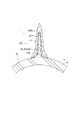
図1は、幾つかの実施形態に係る接合部材の模式的な斜視図である。図2は、一実施形態に係る接合部材の模式的な分解図である。図3は、他の実施形態に係る接合部材の模式的な分解図である。図4は、さらに他の実施形態に係る接合部材の模式的な斜視図である。
図1~4に示した幾つかの実施形態に係る接合部材1は、金属部材10と樹脂部材20とを接合した接合部材である。すなわち、図1~4に示した幾つかの実施形態に係る接合部材1は、金属と樹脂との複合体である。
図1~4に示した幾つかの実施形態に係る金属部材10は、金属製の第1基部11、及び、第1基部11に一体的に設けられた金属製の第1係合部16を含む。
図1~4に示した幾つかの実施形態に係る樹脂部材20は、樹脂製の第2基部21、及び、第2基部21に一体的に設けられるとともに第1係合部16と係合する樹脂製の第2係合部26を含む。
なお、図2、3では、幾つかの実施形態に係る接合部材1において第1係合部16と係合する第2係合部26を、説明のために第1係合部16とは別に描いている。
FIG. 1 is a schematic perspective view of a joint member according to some embodiments. FIG. 2 is a schematic exploded view of a joining member according to one embodiment. FIG. 3 is a schematic exploded view of a joint member according to another embodiment. FIG. 4 is a schematic perspective view of a joint member according to still another embodiment.
A
The
The
2 and 3, the second engaging
以下、図1~4に示した幾つかの実施形態に係る接合部材1の第1係合部16について説明する。幾つかの実施形態に係る接合部材1では、第1係合部16における後述する空洞181に第2係合部26の樹脂が充填されている。そこで、以下の説明では、接合部材1として、金属部材10と樹脂部材20とが接合された状態における説明ではなく、単に第1係合部16の構造について説明する場合、空洞181に第2係合部26の樹脂が充填されていない状態を前提とする。
The first engaging
図1~4に示した幾つかの実施形態に係る接合部材1では、第1係合部16は、金属製のフレーム170により形成され、互いに連通する複数の空洞181を該フレーム170の内部に形成する三次元構造を含んでいる。図1~4に示した幾つかの実施形態に係る接合部材1では、第1係合部16は、少なくとも第1層16aと、第1層16aに積層された第2層16bとを有している。図1~4に示した幾つかの実施形態に係る接合部材1では、フレーム170は、第1層16aにおいて第1方向Dr1に延在する少なくとも一つの第1延在部171と、第2層16bにおいて第1方向D1と交差する第2方向Dr2に延在する少なくとも一つの第2延在部172とを含む。
図1~4に示した幾つかの実施形態に係る接合部材1では、第1方向D1と第2方向D2とは、例えば直交している。
In the
In the
図1~4に示した幾つかの実施形態に係る接合部材1では、説明の便宜上、第1係合部16は、例えば10層構造を有してるものとし、第1層16aから例えば第10層16jまで含んでいる。
図1~3に示した幾つかの実施形態に係る接合部材1では、第1層16aから例えば第10層16jまでのうち、奇数層は第1層16aと同様の構成を有し、偶数層は第2層16bと同様の構成を有する。すなわち、図1~3に示した幾つかの実施形態に係る接合部材1では、第1係合部16は、第1層16aと第2層16bとが交互に繰り返し積層されているということもできる。
なお、説明の便宜上、第1層16aから第10層16jまでの各層の積層方向を単に積層方向、又は、高さ方向とも呼ぶことがあり、積層方向のうち、図1~4における図示上方を上側とし、図1~4における図示下方を下側とする。
In the
In the
For convenience of explanation, the stacking direction of each layer from the
図1~3に示した幾つかの実施形態に係る接合部材1では、第1層16aは、例えば5本の第1延在部171を含んでおり、第1延在部171のそれぞれが隣り合う第1延在部171とは第1方向Dr1と直交する方向(すなわち第2方向Dr2)に離間した状態で並べられている。
図1~3に示した幾つかの実施形態に係る接合部材1では、第2層16bは、例えば4本の第2延在部172を含んでおり、第2延在部172のそれぞれが隣り合う第2延在部172とは第2方向Dr2と直交する方向(すなわち第1方向Dr1)に離間した状態で並べられている。
図1~3に示した幾つかの実施形態に係る接合部材1では、第1層16aにおいて第1延在部171が存在しない領域、及び、第2層16bにおいて第2延在部172が存在しない領域は、第1延在部171及び第2延在部172によって形成された空洞181である。
In the
In the
In the
図4に示した一実施形態に係る接合部材1では、第1層16aから第10層16jまでの各層において、第1基部11から遠ざかるにつれて、第1延在部171又は第2延在部172の本数が少なくなっている。すなわち、図4に示した一実施形態に係る接合部材1では、第1基部11から遠ざかるにつれて、第1係合部16における単位体積当たりのフレーム170の比率が低下する。
In the
図1~4に示した幾つかの実施形態に係る接合部材1は、互いに交差する第1延在部171及び第2延在部172によって形成された井桁構造を有する。なお、図1~4に示した幾つかの実施形態に係る接合部材1では、空洞181は、井桁形状を有する。
The
図1~4に示した幾つかの実施形態に係る接合部材1では、積層方向で互いに接触する第1延在部171と第2層16bとは、実際には一体的に形成されており、互いに接合されている。
図1~4に示した幾つかの実施形態に係る接合部材1では、第1基部11に対して、例えば積層造形法によって、第1係合部16を形成することができる。なお、図1~4に示した幾つかの実施形態に係る第1係合部16の形成方法は、例えば、パウダーベッド方式であってもよく、メタルデポジッション方式であってもよく、バインダージェット方式であってもよく、上述した方式以外の他の方式であってもよい。
また、図1~4に示した幾つかの実施形態に係る第1基部11は、第1係合部16と同様に積層造形法によって形成してもよく、鋳造や鍛造、切削、粉末焼結等によって形成してもよい。
In the
In the
In addition, the
図1~4に示した幾つかの実施形態に係る接合部材1では、第2係合部26は、三次元構造の複数の空洞181内に充填された樹脂270を含む。すなわち、図1~4に示した幾つかの実施形態に係る接合部材1では、第2係合部26は、空洞181と同じ井桁形状を有する。
In the
図2に示す一実施形態では、第2係合部26は、例えば第2基部21と同時に形成されて、第2基部21と一体化されている。図2に示す一実施形態では、第2係合部26を構成する樹脂270は、第2基部21を構成する樹脂220と同じ種類の樹脂である。
そのため、図2に示す一実施形態では、例えば、射出成型の金型に金属部材10をセットし、射出成型装置によって樹脂を射出することで第2係合部26と第2基部21とを得られる。これにより、金属部材10と樹脂部材20とを接合させた接合部材1を容易に得られる。
In one embodiment shown in FIG. 2, the second engaging
Therefore, in the embodiment shown in FIG. 2, for example, the
また、図3に示す一実施形態では、第2係合部26は、例えば予め形成された第2基部21に対して、第2係合部26を形成することで、第2基部21と一体化されている。すなわち、図3に示す一実施形態では、例えば第2係合部26を構成する樹脂270を接着剤として、予め形成された第2基部21を第2係合部26と接着することにより、金属部材10と樹脂部材20とを接合させた接合部材1を得られる。
Moreover, in one embodiment shown in FIG. 3, the second engaging
図3に示す一実施形態では、第2係合部26を構成する樹脂270は、第2基部21を構成する樹脂220と同じ種類の樹脂であってもよく、異なる種類の樹脂であってもよい。
In one embodiment shown in FIG. 3, the
上述したように、図1~4に示した幾つかの実施形態に係る接合部材1では、金属部材10が金属製の第1基部11、及び、第1基部11に一体的に設けられた金属製の第1係合部16を含む。したがって、この金属部材10の第1係合部16に対して樹脂製の第2係合部26及び樹脂製の第2基部21を含む樹脂部材20を形成することで、金属製の第1基部11と樹脂製の第2基部21とを第1係合部16及び第2係合部26によって接合した接合部材1を得られる。
また、図1~4に示した幾つかの実施形態に係る接合部材1では、第1係合部16の複数の空洞181と、該空洞181に充填された第2係合部26の樹脂270とが互いの相対位置の変更を規制することで、第1係合部16と第2係合部26との接合強度を確保できる。これにより、金属部材10と樹脂部材20との接合強度を確保できる。
As described above, in the joining
Moreover, in the
すなわち、図1~4に示した幾つかの実施形態に係る接合部材1では、第1基部11と第2基部21との相対位置を変更しようとしたときにフレーム170の少なくとも一部と空洞181内の樹脂の少なくとも一部とが押圧しあうように構成されている。したがって、図1~4に示した幾つかの実施形態に係る接合部材1では、金属製の第1基部11と樹脂製の第2基部21とが第1係合部16及び第2係合部26によって機械的に結合されているので、金属部材10と樹脂部材20との接合強度を確保できる。
That is, in the
また、図1~4に示した幾つかの実施形態に係る接合部材1では、互いに異なる方向に延在する第1係合部16における第1延在部171及び第2延在部172と、第1係合部16における第1延在部171及び第2延在部172が存在しない空洞181に充填された第2係合部26の樹脂270とによって互いに機械的に結合できる。これにより、金属部材10と樹脂部材20との接合強度を確保できる。
1 to 4, the
上述したように、図4に示した一実施形態に係る接合部材1では、第1層16aから第10層16jまでの各層において、第1基部11から遠ざかるにつれて、第1延在部171又は第2延在部172の本数が少なくなっている。逆に言えば、図4に示した一実施形態に係る接合部材1では、第1層16aから第10層16jまでの各層において、第1基部11に近づくにつれて、第1延在部171又は第2延在部172の本数が多くなっている。すなわち、図4に示した一実施形態に係る接合部材1では、第1係合部16における空洞181とフレーム170とを含む単位体積当たりのフレーム170の比率は、第2基部21に近い領域よりも第1基部11に近い領域の方が大きい。図4に示した一実施形態に係る接合部材1では、例えば、第1層16aにおける単位体積当たりのフレーム170の比率は、第2層16bにおける単位体積当たりのフレーム170の比率よりも大きい。具体的には、図4に示した一実施形態に係る接合部材1では、例えば、第1層16aの第1延在部171の数は、第2層16bの第2延在部172の数よりも多い。
As described above, in the
例えば第1基部11と第2基部21とが互いに離間する方向に引張されると、第1係合部16のフレーム170のうち第1基部11に近い領域におけるフレーム170には、当該領域におけるフレーム170に作用する荷重に加えて、当該領域よりも第2基部21に近い領域におけるフレーム170に作用する荷重を負担することとなる。そのため、第1係合部16の強度の点から、第1係合部16における空洞181とフレーム170とを含む単位体積当たりのフレーム170の比率は、第2基部21に近い領域よりも第1基部11に近い領域の方が大きいことが望ましい。
For example, when the
その点、図4に示した一実施形態に係る接合部材1では、第1係合部16における空洞181とフレーム170とを含む単位体積当たりのフレーム170の比率が第2基部21に近い領域よりも第1基部11に近い領域の方が大きいので、第1係合部16の強度を確保できる。
In this regard, in the
逆に、図4に示した一実施形態に係る接合部材1では、第1係合部16における空洞181とフレーム170とを含む単位体積当たりの空洞181の比率は、第1基部11に近い領域よりも第2基部21に近い領域の方が大きい。したがって、図4に示した一実施形態に係る接合部材1では、第1係合部16と第2係合部26とが係合する領域における単位体積当たりの樹脂270の比率は、第1基部11に近い領域よりも第2基部22に近い領域の方が大きくなる。
上述した第1係合部16の場合と同様に、第2係合部26の強度の点から、第1係合部16と第2係合部26とが係合する領域における単位体積当たりの樹脂270の比率は、第1基部11に近い領域よりも第2基部22に近い領域の方が大きいことが望ましい。
その点、図4に示した一実施形態に係る接合部材1では、第1係合部16と第2係合部26とが係合する領域における単位体積当たりの樹脂270の比率が第1基部11に近い領域よりも第2基部22に近い領域の方が大きいので、第2係合部26の強度を確保できる。
Conversely, in the
As in the case of the first engaging
In this regard, in the
なお、例えば図5に示すように、第1基部11に近づくにつれて、すなわち、図5における図示下方に向かうにつれて、第1延在部171又は第2延在部172について、その延在方向と直交する断面における断面積を大きくするようにしてもよい。図5は、他の実施形態に係る第1係合部16の第1延在部171及び第2延在部172について、その延在方向と直交する断面における断面積について説明するための模式的な図である。図5では、図4に示した一実施形態に係る第1係合部16と同様の構成を有する他の実施形態に係る第1係合部16を、第1延在部171の延在方向に沿って見た、図4における矢視Aに相当する図、及び、第2延在部172の延在方向に沿って見た、図4における矢視Bに相当する図を図示している。なお、図5では、他の実施形態に係る第1係合部16の第1延在部171及び第2延在部172の上記断面積について説明するための図であり、図4に示した一実施形態に係る第1係合部16における第1延在部171及び第2延在部172の形状や配置数等とは一致していない。
For example, as shown in FIG. 5, the
例えば図5に示した他の実施形態では、第1延在部171及び第2延在部172の上下方向の寸法はすべて等しい場合について説明するが、以下の説明に係る趣旨の範囲で、上下方向の寸法が異なっていてもよい。
例えば図5に示した他の実施形態では、第1延在部171の第2方向Dr2に沿った幅Wa1、Wa2は、第1基部11に近づくにつれて、大きくなっている。また、図5に示した他の実施形態では、第2延在部172の第1方向Dr1に沿った幅Wb1、Wb2は、第1基部11に近づくにつれて、大きくなっている。
また、図5に示した他の実施形態では、第1層16aの第1延在部171の第2方向Dr2に沿った幅Wa1は、第2層16bの第2延在部172の第1方向Dr1に沿った幅Wb1よりも大きい。すなわち、図5に示した他の実施形態では、第1層16aの第1延在部171の延在方向と直交する断面における第1延在部171の断面積は、第2層16bの第2延在部172の延在方向と直交する断面における第2延在部172の断面積よりも大きい。
For example, in another embodiment shown in FIG. 5, a description will be given of a case where the vertical dimensions of the
For example, in another embodiment shown in FIG. 5, the widths Wa1 and Wa2 of the first extending
In another embodiment shown in FIG. 5, the width Wa1 along the second direction Dr2 of the first extending
例えば図5に示すように、第1基部11に近づくにつれて、第1延在部171又は第2延在部172について、その延在方向と直交する断面における断面積を大きくするようにしても、第1係合部16における空洞181とフレーム170とを含む単位体積当たりのフレーム170の比率が第2基部21に近い領域よりも第1基部11に近い領域の方が大きくなるので、第1係合部16の強度を確保できる。
なお、上述した図4に示した一実施形態の第1係合部16のように、第1基部11に近づくにつれて第1延在部171又は第2延在部172の本数を増やすことに代えて、図5に示すように、第1基部11に近づくにつれて、第1延在部171又は第2延在部172について、その延在方向と直交する断面における断面積を大きくするようにしてもよい。また、上述した図4に示した一実施形態の第1係合部16のように、第1基部11に近づくにつれて第1延在部171又は第2延在部172の本数を増やすとともに、図5に示すように、第1基部11に近づくにつれて、第1延在部171又は第2延在部172について、その延在方向と直交する断面における断面積を大きくするようにしてもよい。
For example, as shown in FIG. 5, as the
In addition, like the first engaging
(樹脂270の注入に関して)
図6は、さらに他の実施形態に係る第1係合部16を模式的に示した斜視図である。
上述したように、射出成型によって第1係合部16の空洞181に樹脂270を充填することが考えられる。この場合に、例えば第1係合部16の上方からではなく、図6の破線の矢印Sで示すように側方、例えば、第2方向から樹脂270を供給することが考えられる。
このような場合に、樹脂270の注入位置から遠い領域である、図6における図示左方の領域の空洞181に樹脂270を確実に供給するためには、樹脂270の注入位置に近い領域において、樹脂270が流動し易い構造となっていることが望ましい。すなわち、例えば、図6に示すように、樹脂270の注入位置に近い領域における空洞181の大きさが樹脂270の注入位置から遠い領域における空洞181の大きさよりも大きいことが望ましい。
(Regarding injection of resin 270)
FIG. 6 is a perspective view schematically showing a first engaging
As described above, it is conceivable to fill the
In such a case, in order to reliably supply the
そこで、例えば、図6に示したさらに他の実施形態のように、樹脂270の注入位置に近い領域において、第1延在部171又は第2延在部172の少なくとも一方について、その少なくとも一部を切り欠くことによって、空洞181の大きさを大きくするようにしてもよい。例えば、図6に示したさらに他の実施形態では、複数の第1延在部171のうち、樹脂270の注入位置に近い領域の第1延在部171Bは、他の領域の第1延在部171Aの途中を切り欠いたような形状とされている。また、例えば、図6に示したさらに他の実施形態では、複数の第2延在部172のうち、樹脂270の注入位置に近い領域の第2延在部172Bは、他の領域の第2延在部172Aよりも長さが短い。
このように、樹脂270の注入位置に近い領域における空洞181の大きさを樹脂270の注入位置から遠い領域における空洞181の大きさよりも大きくすることで、樹脂270の注入位置から遠い領域にも樹脂270を容易に供給できる。
Therefore, for example, as in still another embodiment shown in FIG. The size of the
In this way, by making the size of the
(樹脂270と第2基部21との接着について)
上述したように、図3に示す一実施形態では、例えば第2係合部26を構成する樹脂270を接着剤として、予め形成された第2基部21を第2係合部26と接着することにより、金属部材10と樹脂部材20とを接合させた接合部材1を得られる。この場合、第2基部21と第2係合部26との接着強度の観点から、第2基部21と第2係合部26(樹脂270)との接触面積が大きい方がよい。
(Adhesion between
As described above, in the embodiment shown in FIG. 3, the pre-formed
例えば、第2基部21を第2係合部26と接着する過程で第2基部21を第1係合部16と接触させる必要がある場合、第2基部21と第1係合部16との接触面積が増えると、第2基部21と樹脂270との接触面積が減ってしまう。そのため、第2基部21と第1係合部16との接触面積を抑制することが望ましい。
そこで、例えば図7に示すように、第2基部21を第2係合部26と接着する過程で第2基部21と接触することとなる、第2基部21に最も近いフレーム170である第1延在部171Cの本数を、該第1延在部171Cよりも第1基部11側に位置する第1延在部171の本数よりも少なくしてもよい。なお、図7は、第2基部21と第1係合部16との接触面積を抑制するための一例を説明するための、第1係合部16の模式的な図である。図7では、第1係合部16の模式的な斜視図、第1係合部16の模式的な正面図、及び、第2基部21と第2係合部26とを接着した後の接合部材1の模式的な正面図を上から順に並べて図示している。
For example, when it is necessary to bring the
Therefore, for example, as shown in FIG. 7, the
また、例えば図8に示すように、第2基部21を第2係合部26と接着する過程で第2基部21と接触することとなる、第2基部21に最も近いフレーム170Aの第1方向Dr1又は第2方向Drの少なくとも一方の大きさを小さくすることで、該フレーム170Aが第2基部21と接触する接触面の面積を小さくしてもよい。なお、図8は、第2基部21と第1係合部16との接触面積を抑制するための他の一例を説明するための、第1係合部16の模式的な図である。図8では、第1係合部16の模式的な斜視図、第1係合部16の模式的な正面図、及び、第2基部21と第2係合部26とを接着した後の接合部材1の模式的な正面図を上から順に並べて図示している。
Further, as shown in FIG. 8, for example, the first direction of the
上述した図7、図8のように、第1係合部16又は第2係合部26と第2基部21とが接する界面251における金属(フレーム170)の面積の比率は、第1係合部16における空洞181とフレーム170とを含む単位体積当たりのフレームの比率の平均値よりも小さい。
したがって、第1係合部16又は第2係合部26と第2基部21とが接する界面251における樹脂270の面積の比率は、第1係合部16における空洞181とフレーム170とを含む単位体積当たりの空洞181の比率の平均値よりも大きくなる。そのため、例えば予め形成しておいた第2基部21を第2係合部26の樹脂270を接着剤として用いて接合する場合、空洞181に充填された接着剤(樹脂270)と第2基部21とが接する面積を増やすことができる。これにより、第2基部21と第2係合部26との接合強度を向上できる。
7 and 8 described above, the ratio of the area of the metal (frame 170) at the
Therefore, the ratio of the area of the
なお、第2基部21と第1係合部16との接触部分において、第2基部21と第1係合部16と嵌合しあう部分を設けると、第2基部21を第2係合部26と接着する過程で第2基部21と第1係合部16との相対位置の位置決めが容易となる。図9は、第2基部21と第1係合部16との接触部分において、第2基部21と第1係合部16とで嵌合しあう部分を設けた場合の一例を説明するための図である。図9では、金属部材10、第2基部21、及び、第2基部21と第1係合部16とを接触させたときの金属部材10と第2基部21とを模式的に示した斜視図である。
In addition, in the contact portion between the
図9に示す例では、図8に示したフレーム170Aの頂部から積層方向の上方に突出する嵌合凸部175が各フレーム170Aに形成されている。また、図9に示す例では、第2基部21と第1係合部16とを接触させたときに嵌合凸部175が挿入される嵌合凹部213が第2基部21の底面、すなわち、第1係合部16と対応する面に形成されている。すなわち、図9に示す例では、接合部材1は、上記界面251を跨いで第1係合部16から第2基部21に向かって突出する嵌合凸部175と、第2基部21に形成され、嵌合凸部175と嵌合する嵌合凹部213とを備える。
In the example shown in FIG. 9, each
例えば予め形成しておいた第2基部21を第2係合部26の樹脂270を接着剤として用いて接合する場合、図9に示す例によれば、嵌合凸部175と嵌合凹部213とを嵌合させることで、第2基部21と第1係合部16、すなわち金属部材10とを容易に位置決めできる。
なお、界面251を跨いだ嵌合関係が図9に示す例とは逆となるように、第2基部21の底面に第1係合部16に向かって突出する嵌合凸部を形成し、フレーム170Aの頂部から積層方向の下方に凹んだ嵌合凹部をフレーム170Aに形成してもよい。すなわち、接合部材1は、上記界面251を跨いで第2基部21から第1係合部16に突出する嵌合凸部と、第1係合部16に形成され、該嵌合凸部と嵌合する嵌合凹部とを備えていてもよい。
For example, when joining the
In addition, a fitting convex portion projecting toward the first engaging
(第1係合部16の形状について)
以下、さらに図10~図17を参照して、第1係合部16の形状についての種々の例を説明する。図10~図17は、それぞれ、第1係合部16の形状についての種々の例を説明するための模式的な断面図である。なお、図10~図17では、第1基部11が例えば円筒形状を有する部材であり、第1基部11の円筒の外周部に第2基部21が配置される場合の例を挙げている。また、図10~14では、第2基部21を接合する前の金属部材10の断面図を図示左側に図示し、第2基部21を接合した後の接合部材1の断面図を図示右側に図示している。図15~17では、第2基部21を接合した後の接合部材1の断面図を図示している。
なお、図10~図17に示した第1係合部16は、上述した図1~9に示した何れかの実施形態に係る第1係合部16であってもよい。
(Regarding the shape of the first engaging portion 16)
Various examples of the shape of the first engaging
Note that the first engaging
以下の説明では、特に断りがない限り、径方向とは、第1基部11の円筒の径方向と同じ方向を表すものとする。また、以下の説明では、特に断りがない限り、軸線方向とは、第1基部11の円筒の軸線方向と同じ方向を表すものとする。以下の説明では、特に断りがない限り、周方向とは、第1基部11の円筒の周方向と同じ方向を表すものとする。
In the following description, unless otherwise specified, the radial direction indicates the same direction as the radial direction of the cylinder of the
図10に示す実施形態では、第1係合部16は、第1基部11の円筒の外周面111に形成されている。図10に示す実施形態では、第1係合部16における径方向外側の面は、平面であるが、曲面であってもよい。
図10に示す実施形態では、第2基部21は、第1係合部16の径方向外側の面に配置されている。
In the embodiment shown in FIG. 10 , the first engaging
In the embodiment shown in FIG. 10 , the
図11、16、17に示す実施形態では、第1係合部16は、第1基部11の円筒の外周面111に形成されている。なお、図11、16、17に示す実施形態に係る第1係合部16は、図10に示す実施形態に係る第1係合部16と比べて径方向の寸法が大きく、例えば、軸線方向から見たときに、径方向外側に向かうにつれて周方向の寸法が小さくなるように形成されている。例えば、図11、16、17に示す実施形態では、第1係合部16は、錐台形状を有しているものとする。すなわち、図11、16、17に示す実施形態では、第1基部11の円筒の外周面111から径方向外側に突出する凸部163が形成されている。
図11、16、17に示す実施形態では、第2基部21は、錐台形状を有する第1係合部16を外側から覆っている。
図11、16、17に示す実施形態では、第2基部21は、上記凸部163が挿入される凹部217を有する。
In the embodiment shown in FIGS. 11 , 16 and 17 , the first engaging
In the embodiments shown in FIGS. 11, 16 and 17, the
11, 16 and 17, the
なお、図17に示す実施形態では、第1基部11には、外周面111から径方向外側に突出する凸部115が形成されている。図17に示す実施形態では、凸部115の外側に第1係合部16(凸部163)が形成されている。
In addition, in the embodiment shown in FIG. 17 , a
図12、13、15に示す実施形態では、第1係合部16は、第1基部11の円筒の外周面111よりも第1基部11における径方向内側に形成されている。すなわち、図12、13、15に示す実施形態では、第1基部11に径方向内側に凹んだ凹部113が形成されており、該凹部113内に第1係合部16が形成されている。すなわち、図12、13、15に示す実施形態では、第1係合部16の基端部167は、第1基部の凹部113に入り込んでいる。
図12、13、15に示す実施形態では、第1係合部16における径方向外側の面は、第1基部11の円筒の外周面111と同じ円筒面とされているが、平面であってもよい。
図12、13、15に示す実施形態では、第2基部21は、第1係合部16の径方向外側の面に配置されている。
In the embodiment shown in FIGS. 12, 13 and 15, the first engaging
In the embodiments shown in FIGS. 12, 13, and 15, the radially outer surface of the first engaging
In the embodiment shown in FIGS. 12, 13 and 15, the
図13に示す実施形態では、第1係合部16は、図12に示す実施形態における第1係合部16に対して、その外周面から径方向内側に凹んだ凹部161が少なくとも1つ形成されている。
図13に示す実施形態では、第2基部21は、上記凹部161に挿入される凸部215を少なくとも1つ有する。
In the embodiment shown in FIG. 13, the first engaging
In the embodiment shown in FIG. 13, the
図14に示す実施形態では、第1基部11に径方向内側に凹んだ凹部113が形成されており、該凹部113内に第1係合部16が形成されている。すなわち、図14に示す実施形態では、第1係合部16の基端部167は、第1基部の凹部113に入り込んでいる。
図14に示す実施形態では、第1係合部16は、図12に示す実施形態における第1係合部16に対して、その外周面から径方向外側に突出する凸部163が少なくとも1つ形成されている。
図14に示す実施形態では、第2基部21は、第1係合部16の径方向外側の面に配置されている。
図14に示す実施形態では、第2基部21は、上記凸部163が挿入される凹部217を少なくとも1つ有する。
In the embodiment shown in FIG. 14 , a
In the embodiment shown in FIG. 14, the first engaging
In the embodiment shown in FIG. 14 , the
In the embodiment shown in FIG. 14, the
図10、11、13、14、16、17に示した実施形態では、第1係合部16は、第1係合部16の外形が凹んだ形状に形成された凹部161、又は、外形が突出した形状に形成された凸部163の少なくとも一方を有している。
そして、図10、11、13、14、16、17に示した実施形態では、第2係合部26は、少なくとも凹部161の形成領域又は凸部163の形成領域において第1係合部16と嵌合している。
図10、11、13、14、16、17に示した実施形態では、第2基部21は、少なくとも凹部161又は凸部163において第2係合部26と接続されている。
これにより、第1係合部16と第2係合部26との係合領域を増やし易くなるので、金属部材10と樹脂部材20との接合強度を確保し易くなる。
In the embodiments shown in FIGS. 10, 11, 13, 14, 16, and 17, the first engaging
In the embodiments shown in FIGS. 10, 11, 13, 14, 16, and 17, the second engaging
In the embodiments shown in FIGS. 10, 11, 13, 14, 16 and 17, the
This makes it easier to increase the engagement area between the first engaging
図11、14、16、17に示した実施形態では、第1係合部16は、凸部163を有している。
そして、図11、14、16、17に示した実施形態では、凸部163は、少なくともその先端部163aが第2基部21で覆われている。すなわち、図11、14、16、17に示した実施形態では、第2基部21の凹部217に凸部163が挿入されている。
これにより、金属部材10と樹脂部材20との相対位置の位置決めが容易になる。
In the embodiments shown in FIGS. 11, 14, 16 and 17, the first engaging
11, 14, 16, and 17, the
This facilitates positioning of the relative positions of the
図17に示した実施形態では、第1基部11は、その一部である凸部115が第1係合部16の凸部163の先端部163aに向かって凸部163に入り込んでいる。
これにより、第1基部11のうち第1係合部16の凸部163に入り込んでいる凸部115によって、第1係合部16の凸部163における強度を容易に補強できる。
In the embodiment shown in FIG. 17, the
As a result, the strength of the
図13に示した実施形態では、第1係合部16は、上記凹部161を有している。そして、図13に示した実施形態では、凹部161は、第2基部21の一部である凸部215が挿入されている。
これにより、図13に示すように、例えば第2基部21が比較的薄い部材であっても、上記凹部161に挿入される部位である凸部215を第2基部21に形成し易い。したがって、例えば第2基部21が比較的薄い部材であっても、金属部材10と樹脂部材20との相対位置の位置決めが容易になる。
In the embodiment shown in FIG. 13, the first engaging
As a result, as shown in FIG. 13, even if the
図12~15に示す実施形態では、第1係合部16の基端部167は、第1基部11の凹部113に入り込んでいる。
これにより、例えば第2基部21の形状等の制約によって第1基部11から第2基部21に向かって突出するような第1係合部16を設けにくい場合であっても、第1基部11の凹部113に第1係合部16を形成することで、第1係合部16と第2係合部26との係合領域を増やし易くなるので、金属部材10と樹脂部材20との接合強度を確保し易くなる。
また、図12~15に示す実施形態では、第1基部11に切削加工や塑性加工等の機械加工を施すことで凹部113を予め形成できる。そして、図12~15に示す実施形態では、予め形成された凹部113に対して、例えば積層造形法によって、互いに連通する複数の空洞181を内部に形成する三次元構造を含む基端部167を形成してもよい。
In the embodiment shown in FIGS. 12-15, the
As a result, even if it is difficult to provide the first engaging
12 to 15, the
なお、上述した幾つかの実施形態に係る第2基部21又は第2係合部26の少なくとも一方は、母材となる樹脂中に繊維を含んでいてもよく、該繊維によって樹脂部材20の強度を向上できる。
ここで、樹脂部材20の母材に含まれる繊維は、カーボンやガラス、セラミックス等の繊維であってもよい。また、該繊維は、射出成型によって第2基部21又は第2係合部26の少なくとも一方を形成する場合には、射出成型を行う際に不都合が生じない程度の比較的短い長さの繊維を用いるとよい。
また、例えば、CFRP(Carbon Fiber Reinforced Plastics:炭素繊維強化プラスチック)などの薄板を型抜きした複数枚のプリプレグシートを積層して構成されたプリプレグ積層体を用いて第2基部21を製造するような場合には、繊維の長さは、特に限定されない。
At least one of the
Here, the fibers contained in the base material of the
Further, for example, the
(接合部材1の製造方法について)
以下、上述した幾つかの実施形態に係る接合部材1の製造方法について説明する。図18は、上述した幾つかの実施形態に係る接合部材1の製造方法のフローチャートである。上述した幾つかの実施形態に係る接合部材1の製造方法は、第2係合部形成工程S100と、第2基部取得工程S200とを備える。
(Regarding the manufacturing method of the joining member 1)
A method for manufacturing the joining
第2係合部形成工程S100は、金属製の第1基部11に一体的に設けられた金属製のフレーム17により形成され、互いに連通する複数の空洞181を内部に形成する三次元構造を含む第1係合部16に対して、複数の空洞181内に樹脂270を充填して第2係合部26を形成する工程である。
第2係合部形成工程S100では、例えば、不図示の射出成型の金型に金属部材10をセットし、不図示の射出成型装置によって樹脂270を射出することで空洞181内に樹脂270を充填することができる。
The second engaging portion forming step S100 includes a three-dimensional structure that is formed by a metal frame 17 that is integrally provided with a metal
In the second engaging portion forming step S100, for example, the
第2基部取得工程S200は、第2係合部26と一体的に設けられる樹脂製の第2基部21を得る工程である。
これにより、第1基部11と一体的に設けられた第1係合部16における複数の空洞181内に樹脂270を充填して第2係合部26を形成するとともに、第2係合部26と一体的に設けられる樹脂製の第2基部21を得ることで、金属製の第1基部11と樹脂製の第2基部21とが接合された接合部材が得られる。
The second base obtaining step S200 is a step of obtaining the resin-made
As a result, the plurality of
なお、複数の空洞181内に樹脂270を充填して第2係合部26を形成するとともに、該樹脂270と同じ種類の樹脂によって第2基部21を形成してもよい。
これにより、例えば、一体的に形成されている金属製の第1基部11及び第1係合部16を不図示の射出成型の金型にセットし、不図示の射出成型装置によって樹脂を射出することで第2係合部26と第2基部21とを得られる。これにより、金属製の第1基部11と樹脂製の第2基部21とが接合された接合部材1を容易に得られる。
It should be noted that the plurality of
Thereby, for example, the integrally formed metal
また、第2基部21と第1係合部16とを複数の空洞181内に充填した樹脂270によって接着してもよい。
これにより、例えば、予め形成しておいた第2基部21を第1係合部16の空洞181内の樹脂270と接合することで一体的に形成されている金属製の第1基部11及び第1係合部16と第2基部21とを接合させた接合部材1を得られる。なお、この場合には、第2係合部26の樹脂270に接着剤を用いることで、該接合部材1を容易に得られる。
Alternatively, the
As a result, for example, the metal
本発明は上述した実施形態に限定されることはなく、上述した実施形態に変形を加えた形態や、これらの形態を適宜組み合わせた形態も含む。
例えば、図1~9に示した幾つかの実施形態では、説明の便宜上、第1基部11の上面が平面であり、該上面に沿って平行に第1延在部171及び第2延在部172が延在している。また、例えば、図1~9に示した幾つかの実施形態では、第1基部11から樹脂部材20の第2基部21に向かって第1係合部16の各層が積層されている。また、例えば、図1~9に示した幾つかの実施形態では、第1延在部171及び第2延在部172は、互いに直交する方向に延在している。しかし、本発明は、これらの態様に限定されない。
The present invention is not limited to the above-described embodiments, and includes modifications of the above-described embodiments and modes in which these modes are combined as appropriate.
For example, in some of the embodiments shown in FIGS. 1-9, for convenience of explanation, the upper surface of the
図19は、第1係合部16の一変形例を示す斜視図である。
例えば図19に示すように、第1延在部171及び第2延在部172は、互いに直交していなくてもよい。すなわち、第1延在部171の延在方向と第2延在部172の延在方向との角度差は、90度以外の角度であってもよい。
また、例えば図19に示すように、第1係合部16の各層の積層方向は、第1基部11から図19において不図示である樹脂部材20の第2基部21に向かう方向(図19における上側に向かう方向)とは異なる方向であってもよい。図19に示す一変形例では、第1係合部16の第1層16aや第2層16b等の各層の積層方向は、第1基部11の上面の延在方向に沿った方向であるが、第1基部11の上面と斜めに交差する方向であってもよい。
すなわち、例えば図19に示した第1係合部16のように、第2層16bは、第1層16aに対して第1基部11から第2基部21へ向かう方向と交差する方向に積層されていてもよい。
FIG. 19 is a perspective view showing a modified example of the first engaging
For example, as shown in FIG. 19, the first extending
Further, as shown in FIG. 19, for example, the lamination direction of each layer of the first engaging
That is, for example, like the first engaging
また、例えば図19に示すように、第1基部11の上面と交差する方向に第1延在部171及び第2延在部172が延在していてもよい。
例えば、図2、3に示した幾つかの実施形態に係る接合部材1では、積層造形時には、第1延在部171及び第2延在部172は、空洞181の鉛直方向直上で、鉛直方向と直交する第1方向Dr1及び第2方向Dr2、すなわち水平方向に延在する。このように、積層造形時に空洞181の鉛直方向の直上で水平方向に延在するようなオーバーハング部分を有する井桁状の第1係合部16をパウダーベッド方式やメタルデポジッション方式の積層造形法で形成することは、一般的には困難である。
しかし、例えば図19に示すように、第1基部11の上面と交差する方向に第1延在部171及び第2延在部172が延在する第1係合部16であれば、積層造形時には、第1延在部171及び第2延在部172が水平方向と交差する方向に延在することとなるので、パウダーベッド方式やメタルデポジッション方式の積層造形法であっても、形成が容易となる。
なお、バインダージェット方式の積層造形法によれば、図2、3に示した第1係合部16のようなオーバーハング部分を有する井桁状の第1係合部16であっても比較的容易に形成できる。
Further, as shown in FIG. 19, for example, the first extending
For example, in the
However, as shown in FIG. 19, for example, if the first engaging
In addition, according to the binder jet type layered manufacturing method, even the first engaging
また、第1係合部16の三次元構造は、第1方向Dr1に延在する少なくとも一つの第1延在部171と、第2方向Dr2に延在する少なくとも一つの第2延在部172とによって構成される井桁状の構造に限られない。すなわち、第1係合部16は、互いに連通する複数の空洞181をフレーム170の内部に形成する三次元構造を含んでいればよい。
図20は、単純な井桁状の構造ではない三次元構造を有する第1係合部16の一例を示す斜視図である。なお、図20では、第1係合部16の一部について図示している。図20に示す一実施形態では、フレーム170は、それぞれ異なる方向に延在する軸部173と、異なる軸部173の端部同士が接続された接続部174とを含んでいる。図20に示す一実施形態では、軸部173は、例えばそれぞれが異なる方向に延在する4つの軸部173a~173dを含んでいる。
The three-dimensional structure of the first engaging
FIG. 20 is a perspective view showing an example of the first engaging
例えば図20に示した第1係合部16のように、第1係合部16は、少なくとも、第1延在方向に延在する複数の第1の軸部173である第1軸状部材と、該第1延在方向と交差する第2延在方向に延在する複数の第2の軸部173である第2軸状部材とを含んでいてもよい。そして、複数の第1の軸部173の少なくとも一つと、複数の第2の軸部173の少なくとも一つとは、接続部174で互いに接続されていてもよい。
For example, like the first engaging
図21は、図20に示す一実施形態における三次元構造の単位格子の斜視図である。図20に示す一実施形態では、三次元構造の単位格子40は、図21に示すように、2つの四角錐41A、41Bの底面同士を重ね合わせた形状を有しており、それぞれの四角錐41A、41Bにおいて、頂点43と底面の角45とを結ぶ線分に相当する位置に軸部173が配置されている。
図20、21に示すような単位格子40を有する第1係合部16であれば、積層造形時には、軸部173が水平方向と交差する方向に延在することとなるので、パウダーベッド方式やメタルデポジッション方式の積層造形法であっても、形成が容易となる。
FIG. 21 is a perspective view of a three-dimensional structural unit cell in one embodiment shown in FIG. In one embodiment shown in FIG. 20, the
In the case of the first engaging
単位格子40の形状は、図21に示した単位格子40の形状に限定されず、様々な形状を採り得る。図22は、単位格子40の形状の幾つかの例を示す図である。第1係合部16の三次元構造は、図21や図22に示した単位格子40の何れか一つ、または複数が繰り返して現れる形状を有していてもよい。
なお、一部の軸部173において、その一端が他の軸部173と接続されていなくてもよい。また、軸部173は、必ずしも直線的に延在していなくてもよく、曲部を有していてもよい。軸部173は、延在方向に沿って径が一定であってもよく、延在方向の位置によって径が変化していてもよい。
また、複数の軸部173が互いに接続される位置は、軸部173の端部に限らず、軸部173の両端の間の位置であってもよい。
The shape of the
Note that one end of some shaft portions 173 may not be connected to other shaft portions 173 . Also, the shaft portion 173 does not necessarily extend linearly, and may have a curved portion. The shaft portion 173 may have a constant diameter along the extending direction, or may vary in diameter depending on the position in the extending direction.
Further, the positions where the plurality of shaft portions 173 are connected to each other are not limited to the ends of the shaft portions 173 , and may be positions between both ends of the shaft portions 173 .
なお、上述した第1係合部16の三次元構造に関する変形例は、これらの変形例以外の構造を排除するものではない。第1係合部16の三次元構造は、連続気孔を有する立体的な網目構造となる様々な形態の三次元構造の何れかを含んでいてもよい。
It should be noted that the modified examples of the three-dimensional structure of the first engaging
1 接合部材
10 金属部材
11 第1基部
16 第1係合部
16a 第1層
16b 第2層
20 樹脂部材
21 第2基部
26 第2係合部
113 凹部
115 凸部
161 凹部
163 凸部
163a 先端部
167 基端部
170 フレーム
171 第1延在部
172 第2延在部
175 嵌合凸部
181 空洞
213 嵌合凹部
215 凸部
217 凹部
220、270 樹脂
251 界面
1 Joining
Claims (15)
樹脂製の第2基部、及び、前記第2基部に一体的に設けられるとともに前記第1係合部と係合する樹脂製の第2係合部を含む樹脂部材と、
を備え、
前記第1係合部は、フレームにより形成され、互いに連通する複数の空洞を該フレームの内部に形成する三次元構造を含み、
前記第2係合部は、前記三次元構造の前記複数の空洞内に充填された樹脂を含み、
前記第1係合部は、少なくとも第1層と、前記第1層に積層された第2層とを有し、
前記フレームは、前記第1層において第1方向に延在する少なくとも一つの第1延在部と、前記第2層において前記第1方向と交差する第2方向に延在する少なくとも一つの第2延在部とを含み、
前記第1層は、前記第2層よりも前記第1基部に近い位置に存在し、
前記第1層における単位体積当たりの前記フレームの比率は、前記第2層における単位体積当たりの前記フレームの比率よりも大きく、
前記第1延在部の数は、前記第2延在部の数よりも多い
接合部材。 a metal member including a metal first base and a metal first engaging portion integrally provided with the first base;
a resin member including a resin-made second base portion and a resin-made second engaging portion that is provided integrally with the second base portion and engages with the first engaging portion;
with
The first engaging portion is formed by a frame and includes a three-dimensional structure that forms a plurality of mutually communicating cavities inside the frame,
the second engaging portion includes a resin filled in the plurality of cavities of the three-dimensional structure;
The first engaging portion has at least a first layer and a second layer laminated on the first layer,
The frame includes at least one first extending portion extending in a first direction on the first layer and at least one second extending portion extending in a second direction crossing the first direction on the second layer. an extension and
The first layer is located closer to the first base than the second layer,
a ratio of the frames per unit volume in the first layer is greater than a ratio of the frames per unit volume in the second layer;
The number of the first extensions is greater than the number of the second extensions
joining material.
前記第2係合部は、少なくとも前記凹部の形成領域又は前記凸部の形成領域において前記第1係合部と嵌合し、
前記第2基部は、少なくとも前記凹部又は前記凸部において前記第2係合部と接続されている
請求項1に記載の接合部材。 The first engaging portion has at least one of a recess formed in a concave shape of the outer shape of the first engaging portion, or a convex portion formed in a protruding shape of the outer shape of the first engaging portion,
The second engaging portion is fitted with the first engaging portion at least in the formation region of the recess or the formation region of the projection,
2. The joining member according to claim 1, wherein the second base is connected to the second engaging portion at least at the concave portion or the convex portion.
前記凸部は、少なくともその先端部が前記第2基部で覆われている
請求項2に記載の接合部材。 The first engaging portion has the convex portion,
3. The joining member according to claim 2, wherein at least a tip portion of the projection is covered with the second base.
請求項3に記載の接合部材。 4. The joining member according to claim 3, wherein a part of said first base portion is inserted into said convex portion toward said tip portion of said convex portion.
前記凹部は、前記第2基部の一部が挿入されている
請求項2乃至4の何れか一項に記載の接合部材。 The first engaging portion has the recess,
The joining member according to any one of claims 2 to 4, wherein a part of the second base is inserted into the recess.
請求項1乃至5の何れか一項に記載の接合部材。 The joining member according to any one of claims 1 to 5, wherein the base end portion of the first engaging portion is inserted into the concave portion of the first base portion.
請求項1乃至6の何れか一項に記載の接合部材。 7. A ratio of the frame per unit volume including the cavity and the frame in the first engaging portion is larger in a region near the first base than in a region near the second base. The joining member according to any one of .
請求項1乃至7のいずれか1項に記載の接合部材。 The cross-sectional area of the first extending portion in the cross section orthogonal to the extending direction of the first extending portion is the cross-sectional area of the second extending portion in the cross section orthogonal to the extending direction of the second extending portion. 8. The joining member according to any one of claims 1 to 7, which is larger than .
請求項1乃至7のいずれか1項に記載の接合部材。 The joining member according to any one of claims 1 to 7 , wherein the second layer is laminated on the first layer in a direction crossing a direction from the first base to the second base.
前記複数の第1軸状部材の少なくとも一つと、前記複数の第2軸状部材の少なくとも一つとは、接続部で互いに接続されている
請求項1乃至7の何れか一項に記載の接合部材。 The first engaging portion includes at least a plurality of first shaft-shaped members extending in a first extending direction and a plurality of second shaft-shaped members extending in a second extending direction intersecting the first extending direction. and a shaft-shaped member,
The joining member according to any one of claims 1 to 7, wherein at least one of the plurality of first shaft-shaped members and at least one of the plurality of second shaft-shaped members are connected to each other at a connecting portion. .
請求項1乃至10の何れか一項に記載の接合部材。 The joining member according to any one of claims 1 to 10 , wherein the resin forming the second engaging portion is the same type of resin as the resin forming the second base portion.
樹脂製の第2基部、及び、前記第2基部に一体的に設けられるとともに前記第1係合部と係合する樹脂製の第2係合部を含む樹脂部材と、
を備え、
前記第1係合部は、フレームにより形成され、互いに連通する複数の空洞を該フレームの内部に形成する三次元構造を含み、
前記第2係合部は、前記三次元構造の前記複数の空洞内に充填された樹脂を含み、
前記第2係合部を構成する樹脂は、前記第2基部を構成する樹脂と異なる種類の樹脂である
接合部材。 a metal member including a metal first base and a metal first engaging portion integrally provided with the first base;
a resin member including a resin-made second base portion and a resin-made second engaging portion that is provided integrally with the second base portion and engages with the first engaging portion;
with
The first engaging portion is formed by a frame and includes a three-dimensional structure that forms a plurality of mutually communicating cavities inside the frame,
the second engaging portion includes a resin filled in the plurality of cavities of the three-dimensional structure;
The joining member, wherein the resin forming the second engaging portion is a different type of resin from the resin forming the second base portion.
請求項12に記載の接合部材。 The ratio of the area of the metal at the interface where the first engaging portion or the second engaging portion and the second base contact each other per unit volume including the cavity and the frame in the first engaging portion 13. The joining member according to claim 12 , which is smaller than the average value of the frame ratios.
前記第2基部又は前記第1係合部に形成され、前記嵌合凸部と嵌合する嵌合凹部と、
をさらに備える
請求項13に記載の接合部材。 a fitting projection straddling the interface and projecting from the second base to the first engaging portion, or projecting from the first engaging portion toward the second base;
a fitting concave portion formed in the second base portion or the first engaging portion and fitted with the fitting convex portion;
14. The joining member of claim 13 , further comprising:
請求項1乃至14の何れか一項に記載の接合部材。
15. The joining member according to any one of claims 1 to 14 , wherein at least one of the second base portion and the second engaging portion contains fibers in a base material resin.
Priority Applications (4)
| Application Number | Priority Date | Filing Date | Title |
|---|---|---|---|
| JP2019031265A JP7193377B2 (en) | 2019-02-25 | 2019-02-25 | Joining material |
| US16/668,113 US20200269479A1 (en) | 2019-02-25 | 2019-10-30 | Bonding member and bonding member manufacturing method |
| CN201911105637.6A CN111605129B (en) | 2019-02-25 | 2019-11-13 | Joint member and method for manufacturing joint member |
| DE102019007936.1A DE102019007936A1 (en) | 2019-02-25 | 2019-11-14 | BONDING ELEMENT AND BONDING ELEMENT MANUFACTURING METHOD |
Applications Claiming Priority (1)
| Application Number | Priority Date | Filing Date | Title |
|---|---|---|---|
| JP2019031265A JP7193377B2 (en) | 2019-02-25 | 2019-02-25 | Joining material |
Publications (2)
| Publication Number | Publication Date |
|---|---|
| JP2020131646A JP2020131646A (en) | 2020-08-31 |
| JP7193377B2 true JP7193377B2 (en) | 2022-12-20 |
Family
ID=72138623
Family Applications (1)
| Application Number | Title | Priority Date | Filing Date |
|---|---|---|---|
| JP2019031265A Active JP7193377B2 (en) | 2019-02-25 | 2019-02-25 | Joining material |
Country Status (4)
| Country | Link |
|---|---|
| US (1) | US20200269479A1 (en) |
| JP (1) | JP7193377B2 (en) |
| CN (1) | CN111605129B (en) |
| DE (1) | DE102019007936A1 (en) |
Families Citing this family (1)
| Publication number | Priority date | Publication date | Assignee | Title |
|---|---|---|---|---|
| JP2023177456A (en) * | 2022-06-02 | 2023-12-14 | 日本軽金属株式会社 | gripper |
Citations (5)
| Publication number | Priority date | Publication date | Assignee | Title |
|---|---|---|---|---|
| JP2006142622A (en) | 2004-11-18 | 2006-06-08 | Mitsubishi Materials Corp | Composite metal porous body and its manufacturing method |
| JP2007262568A (en) | 2005-12-06 | 2007-10-11 | Howmedica Osteonics Corp | Laser-produced porous surface |
| US20140021645A1 (en) | 2012-06-12 | 2014-01-23 | Nassif Elias Rayess | Method of layered construction of polymeric material through open-cell porous material matrix |
| JP2017024246A (en) | 2015-07-21 | 2017-02-02 | 武藤工業株式会社 | Composite resin material |
| WO2017082207A1 (en) | 2015-11-10 | 2017-05-18 | 武藤工業株式会社 | Method for manufacturing shaped object and shaped object |
Family Cites Families (15)
| Publication number | Priority date | Publication date | Assignee | Title |
|---|---|---|---|---|
| JP4242996B2 (en) * | 2000-03-28 | 2009-03-25 | 帝人ファイバー株式会社 | Cushion material molding die manufacturing method |
| US8192815B2 (en) * | 2007-07-13 | 2012-06-05 | Apple Inc. | Methods and systems for forming a dual layer housing |
| JP5578829B2 (en) * | 2009-10-14 | 2014-08-27 | キヤノン株式会社 | Method for producing three-dimensional photonic crystal and functional element |
| US8551280B2 (en) * | 2010-03-17 | 2013-10-08 | Jesse Villarreal, JR. | Solid-core panel incorporating decorative and/or functional material |
| JP5733999B2 (en) * | 2011-01-31 | 2015-06-10 | 大成プラス株式会社 | Method for producing metal resin composite |
| JP2013031943A (en) * | 2011-08-01 | 2013-02-14 | Polyplastics Co | Insert molded article and heat dissipation structure |
| JP2013167713A (en) * | 2012-02-15 | 2013-08-29 | Pioneer Electronic Corp | Manufacturing method of reflection-type plane symmetry imaging element |
| JP5961451B2 (en) * | 2012-05-31 | 2016-08-02 | 富士重工業株式会社 | Bonding structure of fiber reinforced resin and metal |
| CA2888146A1 (en) * | 2012-10-17 | 2014-04-24 | Koji Koizumi | Metal resin composite body and manufacturing method of metal resin composite body |
| JP6550454B2 (en) * | 2015-03-31 | 2019-07-24 | 武藤工業株式会社 | Three-dimensional modeling apparatus, filler feeder, and method of manufacturing shaped article |
| JP6587852B2 (en) * | 2015-07-21 | 2019-10-09 | 武藤工業株式会社 | Composite resin material and manufacturing method thereof |
| CN108927945A (en) * | 2017-05-26 | 2018-12-04 | 日本富拉司特株式会社 | Composite component |
| CN108863445A (en) * | 2018-07-12 | 2018-11-23 | 歌尔股份有限公司 | A kind of preparation method of ceramics and the composite members of plastic cement |
| CN109318506B (en) * | 2018-07-31 | 2020-11-10 | 哈尔滨工程大学 | Composite material net frame type lattice structure and preparation method thereof |
| DE102019201896A1 (en) * | 2019-02-13 | 2020-08-13 | Hyundai Motor Company | 3D-printed (grid-structured) metal - plastic matrix - composite material |
-
2019
- 2019-02-25 JP JP2019031265A patent/JP7193377B2/en active Active
- 2019-10-30 US US16/668,113 patent/US20200269479A1/en not_active Abandoned
- 2019-11-13 CN CN201911105637.6A patent/CN111605129B/en active Active
- 2019-11-14 DE DE102019007936.1A patent/DE102019007936A1/en active Pending
Patent Citations (5)
| Publication number | Priority date | Publication date | Assignee | Title |
|---|---|---|---|---|
| JP2006142622A (en) | 2004-11-18 | 2006-06-08 | Mitsubishi Materials Corp | Composite metal porous body and its manufacturing method |
| JP2007262568A (en) | 2005-12-06 | 2007-10-11 | Howmedica Osteonics Corp | Laser-produced porous surface |
| US20140021645A1 (en) | 2012-06-12 | 2014-01-23 | Nassif Elias Rayess | Method of layered construction of polymeric material through open-cell porous material matrix |
| JP2017024246A (en) | 2015-07-21 | 2017-02-02 | 武藤工業株式会社 | Composite resin material |
| WO2017082207A1 (en) | 2015-11-10 | 2017-05-18 | 武藤工業株式会社 | Method for manufacturing shaped object and shaped object |
Also Published As
| Publication number | Publication date |
|---|---|
| JP2020131646A (en) | 2020-08-31 |
| CN111605129A (en) | 2020-09-01 |
| US20200269479A1 (en) | 2020-08-27 |
| CN111605129B (en) | 2022-05-10 |
| DE102019007936A1 (en) | 2020-08-27 |
Similar Documents
| Publication | Publication Date | Title |
|---|---|---|
| US10501190B2 (en) | Method for homogenous thermoplastic seat back assembly | |
| US7244487B2 (en) | Apparatus, system, and method of joining structural components with a tapered tension bond joint | |
| CA3065462C (en) | Mold made from an additive manufacturing technology | |
| EP2492083B1 (en) | Joint structure for fiber reinforced resin and metal, and joining method for fiber reinforced resin and metal | |
| ES2786124T3 (en) | Manufacturing method of a reinforcing element | |
| JP7193377B2 (en) | Joining material | |
| ES2694625T3 (en) | Assembly procedure and metal-composite assembly | |
| JP6116704B2 (en) | Three-dimensional corner bonded weave preform with lap joint | |
| CN112654445A (en) | Method for forming laminate of bonded article and bonded member | |
| JP5972854B2 (en) | Joining method and joined body of fiber reinforced composite member, and manufacturing method of wind turbine blade | |
| JP4928403B2 (en) | Structure for preventing delamination of sandwich panels | |
| CN110869621B (en) | Apparatus and method for joining panel members | |
| WO2015095042A1 (en) | Composite tensioner arm or guide for timing drive application | |
| CN110641042B (en) | Forming method of X-shaped bracket made of composite material | |
| JP2012528994A5 (en) | ||
| JP7390144B2 (en) | Composite joint members and joint structures | |
| US11560211B2 (en) | Fuselage component for an aircraft, method for producing a fuselage component, and aircraft | |
| JP6820374B2 (en) | Ultrasonic welding member and ultrasonic welding method | |
| JP6230812B2 (en) | Manufacturing method of manifold for fuel cell | |
| CN115163395B (en) | Wind power blade girder segment, girder and wind power blade | |
| KR200491689Y1 (en) | bonded concrete foam | |
| KR101280479B1 (en) | Panel assembly | |
| JP2023012739A (en) | Composite structure and method of manufacturing composite structure | |
| WO2021083699A1 (en) | Noodle | |
| JP2017144576A (en) | Member for ultrasonic deposition and ultrasonic deposition method |
Legal Events
| Date | Code | Title | Description |
|---|---|---|---|
| A621 | Written request for application examination |
Free format text: JAPANESE INTERMEDIATE CODE: A621 Effective date: 20211214 |
|
| A977 | Report on retrieval |
Free format text: JAPANESE INTERMEDIATE CODE: A971007 Effective date: 20221013 |
|
| A131 | Notification of reasons for refusal |
Free format text: JAPANESE INTERMEDIATE CODE: A131 Effective date: 20221018 |
|
| A521 | Request for written amendment filed |
Free format text: JAPANESE INTERMEDIATE CODE: A523 Effective date: 20221108 |
|
| TRDD | Decision of grant or rejection written | ||
| A01 | Written decision to grant a patent or to grant a registration (utility model) |
Free format text: JAPANESE INTERMEDIATE CODE: A01 Effective date: 20221206 |
|
| A61 | First payment of annual fees (during grant procedure) |
Free format text: JAPANESE INTERMEDIATE CODE: A61 Effective date: 20221208 |
|
| R150 | Certificate of patent or registration of utility model |
Ref document number: 7193377 Country of ref document: JP Free format text: JAPANESE INTERMEDIATE CODE: R150 |