EP2669025A1 - Press forming dies - Google Patents
Press forming dies Download PDFInfo
- Publication number
- EP2669025A1 EP2669025A1 EP11857031.6A EP11857031A EP2669025A1 EP 2669025 A1 EP2669025 A1 EP 2669025A1 EP 11857031 A EP11857031 A EP 11857031A EP 2669025 A1 EP2669025 A1 EP 2669025A1
- Authority
- EP
- European Patent Office
- Prior art keywords
- mold
- rod
- design
- design forming
- workpiece
- Prior art date
- Legal status (The legal status is an assumption and is not a legal conclusion. Google has not performed a legal analysis and makes no representation as to the accuracy of the status listed.)
- Withdrawn
Links
Images


Classifications
-
- B—PERFORMING OPERATIONS; TRANSPORTING
- B21—MECHANICAL METAL-WORKING WITHOUT ESSENTIALLY REMOVING MATERIAL; PUNCHING METAL
- B21D—WORKING OR PROCESSING OF SHEET METAL OR METAL TUBES, RODS OR PROFILES WITHOUT ESSENTIALLY REMOVING MATERIAL; PUNCHING METAL
- B21D37/00—Tools as parts of machines covered by this subclass
- B21D37/02—Die constructions enabling assembly of the die parts in different ways
-
- B—PERFORMING OPERATIONS; TRANSPORTING
- B21—MECHANICAL METAL-WORKING WITHOUT ESSENTIALLY REMOVING MATERIAL; PUNCHING METAL
- B21D—WORKING OR PROCESSING OF SHEET METAL OR METAL TUBES, RODS OR PROFILES WITHOUT ESSENTIALLY REMOVING MATERIAL; PUNCHING METAL
- B21D22/00—Shaping without cutting, by stamping, spinning, or deep-drawing
- B21D22/02—Stamping using rigid devices or tools
-
- B—PERFORMING OPERATIONS; TRANSPORTING
- B21—MECHANICAL METAL-WORKING WITHOUT ESSENTIALLY REMOVING MATERIAL; PUNCHING METAL
- B21D—WORKING OR PROCESSING OF SHEET METAL OR METAL TUBES, RODS OR PROFILES WITHOUT ESSENTIALLY REMOVING MATERIAL; PUNCHING METAL
- B21D37/00—Tools as parts of machines covered by this subclass
- B21D37/10—Die sets; Pillar guides
-
- B—PERFORMING OPERATIONS; TRANSPORTING
- B21—MECHANICAL METAL-WORKING WITHOUT ESSENTIALLY REMOVING MATERIAL; PUNCHING METAL
- B21D—WORKING OR PROCESSING OF SHEET METAL OR METAL TUBES, RODS OR PROFILES WITHOUT ESSENTIALLY REMOVING MATERIAL; PUNCHING METAL
- B21D37/00—Tools as parts of machines covered by this subclass
- B21D37/20—Making tools by operations not covered by a single other subclass
-
- B—PERFORMING OPERATIONS; TRANSPORTING
- B30—PRESSES
- B30B—PRESSES IN GENERAL
- B30B15/00—Details of, or accessories for, presses; Auxiliary measures in connection with pressing
- B30B15/02—Dies; Inserts therefor; Mounting thereof; Moulds
Definitions
- the present invention relates to a mold for press forming.
- Patent Document 1 proposes a device to make it easier to remove a formed workpiece from the mold.
- Patent Document 2 proposes a mold in which a part of the mold or a punch can be moved, and which can thereby accommodate differing press shapes without exchanging the entire mold.
- the present specification presents a technique for improving the mold from a viewpoint different from Patent Document 1 and Patent Document 2.
- the present specification presents a technique for reducing the weight of the mold.
- a design forming portion of the mold is constructed with a rod shaped member.
- the design forming portion makes contact with a workpiece during a press forming process and thereby forms a target design on the workpiece.
- the present invention reduces the weight of the mold.
- a design surface for forming the target design on the workpiece is configured of the rod shaped member.
- the rod shaped member that constitutes the design forming portion is called a design forming rod or a first rod member.
- the weight is further reduced.
- the rod member that supports the first rod member is called a supporting rod or a second rod member.
- the design forming rod and the supporting rod constitute a framework structure. More preferably, with the novel mold taught in the present specification, the design forming rod and the supporting rod constitute a truss structure.
- the truss structure refers to a structure in which moment does not occur in the rod members, and only load in the axial direction occurs. High strength can be expected from the truss structure.
- the design forming rod and the supporting rod may constitute a compassion structure. Further, the compassion structure refers to a structure in which both load in the axial direction and moment occur in the rod members.
- a high load is applied from a press machine to the design forming portion (the design forming rod).
- the supporting rod extends parallel to the direction of load applied by the press machine and that a center line of the supporting rod in its longitudinal direction passes through the first rod member. According to such a configuration, the load from the press machine is applied in the axial direction of the supporting rod. Since the rod member is resistant to load in the axial direction, this configuration has the advantage that the load resistance of the design forming rod (the design forming portion) is high.
- the mold for press forming requires a block for positioning the mold. Specifically, a block is required for fixing the mold to the press machine. In a more preferred aspect of the above mold, a block for positioning the mold may be connected to the second rod member.
- the mold is preferably manufactured by a casting process, in particular, by a full mold casting process.
- Fig.1 is a schematic side view of a press machine 50 having molds 2, 32.
- the press machine 50 comprises a pair of molds, i.e., the upper mold 32 and the lower mold 2.
- the lower mold 2 is fixed to a bolster 51 of the press machine 50, and the upper mold 32 is fixed to a slider 52.
- the slider 52 is moved up and down by an actuator 55 while being guided by supports 53.
- the press machine 50 comprises a clamp for retaining a workpiece W, although this clamp is not shown.
- the clamp is disposed at the sides of the molds 2, 32.
- Fig. 2 shows a perspective view of the upper mold 32 and the lower mold 2.
- Fig. 3 shows a cross-sectional view of the upper mold 32 and the lower mold 2.
- Fig. 3 is equivalent to a cross-section along the line III-III of Fig. 2 .
- the bolster 51 supporting the lower mold 2 is shown in Fig. 2 , but the slider 52 supporting the upper mold 32 is not shown.
- Fig. 3 shows the upper mold 32 having been lowered to a lowermost position, this being a state for forming the workpiece W into a target design.
- the molds 2, 32 form a flat metal sheet (the workpiece W) into a rectangular convex shape (a workpiece Wb).
- a Z-axis of the coordinates in the figures indicates a direction of movement of the slider 52 (i.e., the upper mold 32).
- the Z-axis direction also corresponds to the direction of load applied by the press machine 50.
- the molds 2, 32 will be described.
- the lower mold 2 is configured of a design forming rod 4, supporting rods 6, 8, 10, 12, and positioning blocks 14.
- the upper mold 32 is configured of a design forming rod 34, supporting rods 36, 38, 40, and positioning blocks 44.
- the design forming rods 4, 34 correspond to design forming portions for forming the workpiece W into the target design.
- a rectangular base is formed by the supporting rods 8 and 10, and the four supporting rods 6 extend parallel to one another in a perpendicular manner from the four corners of this base.
- the design forming rod 4 is fixed to upper ends of the four supporting rods 6.
- the design forming rod 4 in entirety, forms a rectangular ring with rounded corners. Further, a cross-section of the design forming rod 4 also forms a rectangle with rounded corners. A part of the cross-section of the design forming rod 4 (a part of a side surface of the design forming rod 4) conforms to a target shape.
- the supporting rod 12 is attached in order to reinforce the design forming rod 4. As shown in Fig.
- the positioning blocks 14 are connected to end parts of the two supporting rods 8 that extend parallel to one another. When viewing the lower mold 2 from a plan view, the four positioning blocks 14 are seen in four corners surrounding the design forming rod 4.
- the positioning blocks 14 are parts for fixing the lower mold 2 to the bolster 51 of the press machine.
- the reference number 16 indicates bolts for fixing the positioning blocks 14 to the bolster 51.
- a rectangular base is formed by the supporting rods 38 and 40, and the four supporting rods 36 extend parallel to one another in a perpendicular manner from the four corners of this base.
- the design forming rod 34 is fixed to lower ends of the four supporting rods 36.
- the positioning blocks 44 are connected to end parts of the two supporting rods 38 that extend parallel to one another. When viewing the upper mold 32 from a plan view, the four positioning blocks 44 are seen in four corners surrounding the design forming rod 4.
- the positioning blocks 44 are parts for fixing the upper mold 32 to the slider 52 of the press machine 50.
- the reference number 45 indicates through holes through which bolts 46 for fixing the positioning blocks 44 pass.
- the overall shape of the design forming rod 34 is similar to the shape of the design forming rod 4 of the lower mold 2.
- the ring of the design forming rod 34 has a size larger than the ring of the design forming rod 4.
- the ring of the design forming rod 34 has the size with which the ring fits with an outside of the ring of the design forming rod 4 with a clearance which is the same as the thickness of the workpiece W.
- the workpiece W is sandwiched between the design forming rods 4 and 34, load from above and below is applied, thus forming the target design on the workpiece W.
- the design forming rods 4, 34 make contact with the workpiece, but the supporting rods do not make contact with the workpiece W. That is, only the design forming rods 4, 34 make contact with the workpiece W, and form the workpiece into a target shape by using the load applied by the press machine 50.
- the design forming rod 4 and the supporting rods 6, 8, 10 constitute a bistable structure (a framework structure).
- the design forming rod 34 and the supporting rods 36, 38, 40 constitute a termed structure (a framework structure).
- the molds 2, 32 are almost entirely composed of the rod members. In particular, by having the design forming portions configured of the rod members (design forming rods), the weight can be reduced.
- each supporting rod 6 extends parallel to the direction in which load is applied by the press machine (the Z-axis direction).
- a longitudinal center line CL1 of each supporting rod 6 passes through the design forming rod 4.
- the supporting rods 36 extend parallel to the direction in which load is applied by the press machine (the Z direction), and a longitudinal center line CL2 of each supporting rod 36 passes through the design forming rod 34. Consequently, the supporting rods 36 of the upper mold 32 also catch, as the axial thrust load, the load which the design forming rod 34 receives from the press machine.
- the upper mold 32 also realizes a high load resistance.
- the molds 2, 32 are made by a casting process, specifically, by full mold casting. Consequently, evaporative patterns having the same shapes as the molds 2 and 32 shown in Fig. 2 are made.
- the evaporative patterns are made from polystyrene foam.
- the entire evaporative pattern of the lower mold 2 (or the upper mold 32) may be made in one piece, or may be made as a plurality of separate pieces.
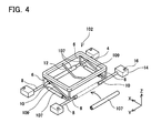
- Fig. 4 shows a modified lower mold 102.
- a rod main body 107 (a part other than end joints) of each supporting rod consists of a part separate from the joint portions.
- a reinforcing member 109 has been added at locations where the strength of the lower mold 102 tends to be insufficient.
- Each reinforcing member 109 is positioned along the diagonal of a lattice of the framework structure (a lattice surrounded by adjacent rod members). The reinforcing members may be attached at locations other than the locations shown in Fig. 4 .
- the reinforcing members are positioned such that the amount of bending of each part when a scheduled load (or maximum load) is applied to the mold 102 is equal to or less than a predetermined permissible amount. Moreover, the location where the reinforcing member 109 is attached constitutes the truss structure (framework structure). By constituting the truss structure, the lower mold 102 can realize high strength while being lightweight.
- the design forming rods (4, 34) correspond to one aspect of the first rod member.
- the supporting rods (6, 8, 10, 12, 36, 38, 40) correspond to one aspect of the second rod member.
- the cross-sectional shape of the design forming rods 4, 34 in particular the shape of the rod end surface that makes contact with the workpiece W, must be made in a shape corresponding to the pressed shape (the target design) of the workpiece.
- the cross-sectional shape of the supporting rods (6, 8, 10, 12, 36, 38, 40) may be a shape other than round.
- the cross-sectional shape of the supporting rods may be oval or polygonal.
- the supporting rods need not be a straight line, but may be bent, like the supporting rod 12, or may be curved.
- the molds 2, 32 have a framework structure that includes the design forming portion. Consequently, the molds 2, 32 also have the advantage that removal of the workpiece from the mold after press forming is easy.
- the overall shape of the mold i.e., the shape of the framework structure, is not limited to the shape of the present embodiment. Further, the shape and number of the design forming rods is not limited to the mold of the present embodiment. For example, in order to achieve a complex press shape, the mold may comprise a plurality of design forming rods.
Landscapes
- Engineering & Computer Science (AREA)
- Mechanical Engineering (AREA)
- Shaping Metal By Deep-Drawing, Or The Like (AREA)
- Mounting, Exchange, And Manufacturing Of Dies (AREA)
- Forging (AREA)
Abstract
Description
- The present invention relates to a mold for press forming.
- Many improvements for molds for press forming have been proposed. For example,
Patent Document 1 proposes a device to make it easier to remove a formed workpiece from the mold.Patent Document 2 proposes a mold in which a part of the mold or a punch can be moved, and which can thereby accommodate differing press shapes without exchanging the entire mold. -
- Patent Document 1: Japanese Patent Application Publication No.
H6-269866 - Patent Document 2: Japanese Patent Application Publication No.
H7-16670 - The present specification presents a technique for improving the mold from a viewpoint different from
Patent Document 1 andPatent Document 2. The present specification presents a technique for reducing the weight of the mold. - In one aspect of a mold taught in the present specification, a design forming portion of the mold is constructed with a rod shaped member. The design forming portion makes contact with a workpiece during a press forming process and thereby forms a target design on the workpiece. By having the design forming portion be constructed with the rod shaped member, the present invention reduces the weight of the mold. In other words, a design surface for forming the target design on the workpiece is configured of the rod shaped member. Below, the rod shaped member that constitutes the design forming portion is called a design forming rod or a first rod member.
- If a member that supports the first rod member (the design forming rod) is also configured of a rod member, the weight is further reduced. Below, the rod member that supports the first rod member is called a supporting rod or a second rod member. The design forming rod and the supporting rod constitute a framework structure. More preferably, with the novel mold taught in the present specification, the design forming rod and the supporting rod constitute a truss structure. The truss structure refers to a structure in which moment does not occur in the rod members, and only load in the axial direction occurs. High strength can be expected from the truss structure. Moreover, for the strength and rigidity of the rod members to withstand the load, the design forming rod and the supporting rod may constitute a Rahmen structure. Further, the Rahmen structure refers to a structure in which both load in the axial direction and moment occur in the rod members.
- In the press forming process, a high load is applied from a press machine to the design forming portion (the design forming rod). In order to support the design forming rod strongly, it is preferred that the supporting rod extends parallel to the direction of load applied by the press machine and that a center line of the supporting rod in its longitudinal direction passes through the first rod member. According to such a configuration, the load from the press machine is applied in the axial direction of the supporting rod. Since the rod member is resistant to load in the axial direction, this configuration has the advantage that the load resistance of the design forming rod (the design forming portion) is high.
- The mold for press forming requires a block for positioning the mold. Specifically, a block is required for fixing the mold to the press machine. In a more preferred aspect of the above mold, a block for positioning the mold may be connected to the second rod member.
- The mold is preferably manufactured by a casting process, in particular, by a full mold casting process.
-
-
Fig. 1 shows a schematic side view of a press machine. -
Fig. 2 shows a perspective view of a mold (an upper mold and a lower mold). -
Fig. 3 shows a cross-sectional view of the mold. -
Fig. 4 is a figure illustrating a modification of the mold. - An embodiment of a mold will be described with reference to figures. To aid understanding, the mold will be described together with a press machine.
Fig.1 is a schematic side view of apress machine 50 havingmolds press machine 50 comprises a pair of molds, i.e., theupper mold 32 and thelower mold 2. Thelower mold 2 is fixed to abolster 51 of thepress machine 50, and theupper mold 32 is fixed to aslider 52. Theslider 52 is moved up and down by anactuator 55 while being guided bysupports 53. Moreover, in addition to these parts, thepress machine 50 comprises a clamp for retaining a workpiece W, although this clamp is not shown. The clamp is disposed at the sides of themolds -
Fig. 2 shows a perspective view of theupper mold 32 and thelower mold 2.Fig. 3 shows a cross-sectional view of theupper mold 32 and thelower mold 2.Fig. 3 is equivalent to a cross-section along the line III-III ofFig. 2 . Moreover, it should be noted that thebolster 51 supporting thelower mold 2 is shown inFig. 2 , but theslider 52 supporting theupper mold 32 is not shown. Further,Fig. 3 shows theupper mold 32 having been lowered to a lowermost position, this being a state for forming the workpiece W into a target design. As shown inFigs. 2 and3 , themolds press machine 50. - The
molds lower mold 2 is configured of adesign forming rod 4, supportingrods positioning blocks 14. Theupper mold 32 is configured of adesign forming rod 34, supportingrods positioning blocks 44. Thedesign forming rods - The structure of the
lower mold 2 will be described. A rectangular base is formed by the supportingrods rods 6 extend parallel to one another in a perpendicular manner from the four corners of this base. Thedesign forming rod 4 is fixed to upper ends of the four supportingrods 6. Thedesign forming rod 4, in entirety, forms a rectangular ring with rounded corners. Further, a cross-section of thedesign forming rod 4 also forms a rectangle with rounded corners. A part of the cross-section of the design forming rod 4 (a part of a side surface of the design forming rod 4) conforms to a target shape. The supportingrod 12 is attached in order to reinforce thedesign forming rod 4. As shown inFig. 3 , the vicinity of the center of the supportingrod 12 is bent, so as not to interfere with the workpiece W, toward a back side of the mold (the bolster 51 side). The positioning blocks 14 are connected to end parts of the two supportingrods 8 that extend parallel to one another. When viewing thelower mold 2 from a plan view, the fourpositioning blocks 14 are seen in four corners surrounding thedesign forming rod 4. The positioning blocks 14 are parts for fixing thelower mold 2 to the bolster 51 of the press machine. Thereference number 16 indicates bolts for fixing the positioning blocks 14 to the bolster 51. - The structure of the
upper mold 32 will be described. A rectangular base is formed by the supportingrods rods 36 extend parallel to one another in a perpendicular manner from the four corners of this base. Thedesign forming rod 34 is fixed to lower ends of the four supportingrods 36. The positioning blocks 44 are connected to end parts of the two supportingrods 38 that extend parallel to one another. When viewing theupper mold 32 from a plan view, the fourpositioning blocks 44 are seen in four corners surrounding thedesign forming rod 4. The positioning blocks 44 are parts for fixing theupper mold 32 to theslider 52 of thepress machine 50. Thereference number 45 indicates through holes through whichbolts 46 for fixing the positioning blocks 44 pass. - The overall shape of the
design forming rod 34 is similar to the shape of thedesign forming rod 4 of thelower mold 2. However, the ring of thedesign forming rod 34 has a size larger than the ring of thedesign forming rod 4. Specifically, the ring of thedesign forming rod 34 has the size with which the ring fits with an outside of the ring of thedesign forming rod 4 with a clearance which is the same as the thickness of the workpiece W. As described above, the workpiece W is sandwiched between thedesign forming rods design forming rods design forming rods press machine 50. - As shown in
Fig. 2 , in thelower mold 2, thedesign forming rod 4 and the supportingrods upper mold 32, thedesign forming rod 34 and the supportingrods molds - As shown in
Fig. 3 , each supportingrod 6 extends parallel to the direction in which load is applied by the press machine (the Z-axis direction). A longitudinal center line CL1 of each supportingrod 6 passes through thedesign forming rod 4. By means of such a structure, the supportingrods 6 catch, as an axial thrust load, the load applied to the design forming rod 4 (the load applied by the press machine). The rod members have a high load resistance for axial thrust loads. Consequently, since the supportingrods 6 receive the load applied by the press machine as an axial thrust load, a high load resistance of thelower mold 2 is realized. - The same applies for the
upper mold 32. That is, the supportingrods 36 extend parallel to the direction in which load is applied by the press machine (the Z direction), and a longitudinal center line CL2 of each supportingrod 36 passes through thedesign forming rod 34. Consequently, the supportingrods 36 of theupper mold 32 also catch, as the axial thrust load, the load which thedesign forming rod 34 receives from the press machine. Theupper mold 32 also realizes a high load resistance. - The
molds molds Fig. 2 are made. The evaporative patterns are made from polystyrene foam. The entire evaporative pattern of the lower mold 2 (or the upper mold 32) may be made in one piece, or may be made as a plurality of separate pieces. - One modification of the mold of the embodiment will be described.
Fig. 4 shows a modifiedlower mold 102. In thislower mold 102, a rod main body 107 (a part other than end joints) of each supporting rod consists of a part separate from the joint portions. Further, a reinforcingmember 109 has been added at locations where the strength of thelower mold 102 tends to be insufficient. Each reinforcingmember 109 is positioned along the diagonal of a lattice of the framework structure (a lattice surrounded by adjacent rod members). The reinforcing members may be attached at locations other than the locations shown inFig. 4 . The reinforcing members are positioned such that the amount of bending of each part when a scheduled load (or maximum load) is applied to themold 102 is equal to or less than a predetermined permissible amount. Moreover, the location where the reinforcingmember 109 is attached constitutes the truss structure (framework structure). By constituting the truss structure, thelower mold 102 can realize high strength while being lightweight. - Notes concerning the
molds design forming rods rod 12, or may be curved. - The
molds molds - The overall shape of the mold, i.e., the shape of the framework structure, is not limited to the shape of the present embodiment. Further, the shape and number of the design forming rods is not limited to the mold of the present embodiment. For example, in order to achieve a complex press shape, the mold may comprise a plurality of design forming rods.
- Specific examples of the present invention are described above in detail, but these examples are merely illustrative and place no limitation on the scope of the claims. The technology described in the claims also encompasses various changes and modifications to the specific examples described above. The technical elements explained in the present specification or drawings provide technical utility either independently or through various combinations. The present invention is not limited to the combinations described at the time the claims are filed. Further, the purpose of the examples illustrated by the present specification or drawings is to satisfy multiple objectives simultaneously, and satisfying any one of those objectives gives technical utility to the present invention.
- 2: Mold (Lower Mold), 4, 34: Design Forming Rods (First Rod Members), 6, 8, 10, 12, 36, 38, 40: Supporting Rods (Second Rod Members), 14, 44: Positioning Blocks, 32: Mold (Upper Mold), 50: Press Machine, 51: Bolster, 52: Slider, 53: Support, 55: Actuator, 102: Mold (Lower Mold), 107: Rod Main Body, 109: Reinforcing Member
Claims (6)
- A mold for press forming, wherein a design forming portion thereof is constructed with a rod shaped member (a first rod member), the design forming portion being configured to make contact with a workpiece and form a target design on the workpiece.
- The mold of claim 1 further comprising a second rod member that supports the first rod member.
- The mold of claim 2, wherein the first and second rod members constitute a framework structure.
- The mold of claim 2 or 3, wherein:the second rod member extends parallel to a direction of load applied by a press machine; anda center line of the second rod member passes through the first rod member.
- The mold of any one of claims 2 to 4, wherein a block for positioning the mold is connected to the second rod member.
- The mold of any one of claims 1 to 5, wherein the mold is manufactured by a casting process.
Applications Claiming Priority (1)
| Application Number | Priority Date | Filing Date | Title |
|---|---|---|---|
| PCT/JP2011/051826 WO2012101830A1 (en) | 2011-01-28 | 2011-01-28 | Press forming dies |
Publications (3)
| Publication Number | Publication Date |
|---|---|
| EP2669025A1 true EP2669025A1 (en) | 2013-12-04 |
| EP2669025A8 EP2669025A8 (en) | 2014-02-26 |
| EP2669025A4 EP2669025A4 (en) | 2014-07-30 |
Family
ID=46580426
Family Applications (1)
| Application Number | Title | Priority Date | Filing Date |
|---|---|---|---|
| EP20110857031 Withdrawn EP2669025A4 (en) | 2011-01-28 | 2011-01-28 | PUNCHES FOR PRESS FORMING |
Country Status (6)
| Country | Link |
|---|---|
| US (1) | US9126253B2 (en) |
| EP (1) | EP2669025A4 (en) |
| JP (1) | JP5458341B2 (en) |
| KR (1) | KR101474178B1 (en) |
| CN (1) | CN103338874B (en) |
| WO (1) | WO2012101830A1 (en) |
Families Citing this family (6)
| Publication number | Priority date | Publication date | Assignee | Title |
|---|---|---|---|---|
| US9828128B1 (en) | 2014-12-17 | 2017-11-28 | X Development Llc | On-demand protective structures for packaging items in a container |
| US9840347B1 (en) | 2014-12-17 | 2017-12-12 | X Development LLX | Adhering modular elements for packaging structures |
| CN107537894A (en) * | 2017-10-20 | 2018-01-05 | 中核(天津)科技发展有限公司 | A kind of forcing press plate-bending apparatus and bent plate method |
| JP7032949B2 (en) * | 2018-02-14 | 2022-03-09 | 三桜工業株式会社 | Bending mold |
| CN111515346A (en) * | 2020-04-29 | 2020-08-11 | 南通奥里斯特机械有限公司 | Manufacturing process of stamping die |
| CN116348217A (en) | 2020-10-06 | 2023-06-27 | 日本制铁株式会社 | Mold and pressure forming device |
Family Cites Families (41)
| Publication number | Priority date | Publication date | Assignee | Title |
|---|---|---|---|---|
| US774818A (en) * | 1903-12-05 | 1904-11-15 | Pittsburg Forge And Iron Company | Bending-die. |
| US1449385A (en) * | 1919-05-20 | 1923-03-27 | Ludwig M Dieterich | Art and apparatus for forcing material into a predetermined form |
| US1940305A (en) * | 1930-11-22 | 1933-12-19 | Chrysler Corp | Method of making rear axle housings |
| US2133477A (en) * | 1937-06-23 | 1938-10-18 | Henry E Schade | Plate bending press |
| US2483597A (en) * | 1946-03-22 | 1949-10-04 | Heppenstall Co | Supplemental forging press die |
| US2681027A (en) * | 1950-04-01 | 1954-06-15 | Sheffield Corp | Metal shaping or drawing dies |
| US2722174A (en) * | 1950-11-24 | 1955-11-01 | Hydropress Inc | Hydraulic press |
| US3172453A (en) * | 1962-12-31 | 1965-03-09 | Todd Shipyards Corp | Position control for multiple tools |
| US3418922A (en) * | 1967-01-03 | 1968-12-31 | Barogenics Inc | Load-bearing frame structure |
| US3845654A (en) * | 1973-07-13 | 1974-11-05 | Caterpillar Tractor Co | Die forming apparatus |
| US3889513A (en) * | 1973-12-26 | 1975-06-17 | Mitsubishi Heavy Ind Ltd | Apparatus for bending a steel plate |
| JPS51141766A (en) * | 1975-06-02 | 1976-12-06 | Sekisui Jushi Kk | Method of manufacturing metalic staples coated with synthetic resin |
| US4088002A (en) * | 1975-07-10 | 1978-05-09 | G.C. Barnes Tooling And Mfg. Co., Inc. | Method and means of straightening cycle frames |
| GB1604495A (en) * | 1978-05-30 | 1981-12-09 | Hawkhead Bray & Sons Ltd | Press action machines |
| GB2094681B (en) * | 1981-03-18 | 1984-11-21 | Rockwell International Corp | Bending |
| JPS60141339A (en) * | 1983-12-28 | 1985-07-26 | Nissan Motor Co Ltd | Reverse drawing press device |
| US4706490A (en) * | 1986-01-23 | 1987-11-17 | Press Technology Corp. | Forging press with yoke design for attaching tie-rods to crossheads |
| US4760729A (en) * | 1986-03-27 | 1988-08-02 | The Stolle Corporation | Dual ram press |
| JPH01197027A (en) * | 1988-01-30 | 1989-08-08 | Mazda Motor Corp | Method for manufacturing metal die |
| US4878374A (en) * | 1988-05-20 | 1989-11-07 | Nelson Richard E | Five bar linkage mechanism |
| US5184496A (en) * | 1988-07-08 | 1993-02-09 | Honda Giken Kogyo Kabushiki Kaisha | Pressing die |
| US5040966A (en) * | 1988-11-02 | 1991-08-20 | Tetrahex, Inc. | Die for making a tetrahexagonal truss structure |
| FI922191A7 (en) * | 1992-05-14 | 1993-11-15 | Kvaerner Masa Yards Oy | SFAERISK LNG TANK OCH DESS FRAMSTAELLNINGSFOERFARANDE |
| US5315856A (en) * | 1992-08-07 | 1994-05-31 | Lips Propellers, Inc. | Apparatus for propeller straightening |
| JPH06210351A (en) * | 1993-01-11 | 1994-08-02 | Sumitomo Light Metal Ind Ltd | Press mold for bending plate materials |
| JPH06226365A (en) * | 1993-02-05 | 1994-08-16 | Hitachi Ltd | Curved plastic working equipment |
| JPH06269866A (en) | 1993-03-24 | 1994-09-27 | Mazda Motor Corp | Press forming device |
| JP3483592B2 (en) | 1993-07-07 | 2004-01-06 | 株式会社アマダ | Mold |
| US5433418A (en) * | 1993-12-22 | 1995-07-18 | United Technologies Corporation | Selectively-flexible mold having a shell supported by a collapsible truss structure |
| JPH07323400A (en) * | 1994-06-03 | 1995-12-12 | Toyota Motor Corp | Press mold and its manufacturing method |
| US5546784A (en) * | 1994-12-05 | 1996-08-20 | Grumman Aerospace Corporation | Adjustable form die |
| US5701651A (en) * | 1995-05-26 | 1997-12-30 | The Boeing Company | Composite stringer and skin panel assembly machine |
| WO1998019843A1 (en) * | 1996-11-08 | 1998-05-14 | Nu-Cast Inc. | Improved truss structure design |
| JP2003245728A (en) * | 2002-02-20 | 2003-09-02 | Honda Motor Co Ltd | Sheet material forming method |
| US6907820B2 (en) * | 2003-03-20 | 2005-06-21 | Mitek Holdings, Inc. | Press for assembling structures |
| KR100830822B1 (en) * | 2006-12-27 | 2008-05-19 | 주식회사 포스코 | Blank Aligner for Hot Press Forming |
| DE102007012860B4 (en) * | 2007-03-17 | 2010-08-26 | Schuler Pressen Gmbh & Co. Kg | Tool for a variable stiffness press |
| DE102007023269A1 (en) * | 2007-05-18 | 2008-11-20 | Bayerische Motoren Werke Aktiengesellschaft | Drawing tool for production of 3-dimentional sheets, especially of body structural parts, has functional surface and at least one profiled fillet, is useful in motor vehicle body production, is simple to produce and shortens clock time |
| ES2444420T3 (en) * | 2009-09-12 | 2014-02-25 | Franz Kaldewei Gmbh & Co. Kg | Useful arrangement for forming a cuvette edge in a metal cuvette blank |
| CN201613307U (en) * | 2009-11-10 | 2010-10-27 | 浙江吉利汽车有限公司 | Drawing die for car door outer panel |
| JP5382231B2 (en) * | 2010-12-22 | 2014-01-08 | トヨタ自動車株式会社 | Mold for machine press |
-
2011
- 2011-01-28 EP EP20110857031 patent/EP2669025A4/en not_active Withdrawn
- 2011-01-28 JP JP2012554602A patent/JP5458341B2/en active Active
- 2011-01-28 WO PCT/JP2011/051826 patent/WO2012101830A1/en not_active Ceased
- 2011-01-28 KR KR1020137011321A patent/KR101474178B1/en not_active Expired - Fee Related
- 2011-01-28 US US13/879,632 patent/US9126253B2/en active Active
- 2011-01-28 CN CN201180066093.2A patent/CN103338874B/en active Active
Also Published As
| Publication number | Publication date |
|---|---|
| EP2669025A4 (en) | 2014-07-30 |
| CN103338874A (en) | 2013-10-02 |
| KR20130094334A (en) | 2013-08-23 |
| WO2012101830A1 (en) | 2012-08-02 |
| EP2669025A8 (en) | 2014-02-26 |
| JPWO2012101830A1 (en) | 2014-06-30 |
| JP5458341B2 (en) | 2014-04-02 |
| US9126253B2 (en) | 2015-09-08 |
| KR101474178B1 (en) | 2014-12-17 |
| CN103338874B (en) | 2015-10-21 |
| US20130291614A1 (en) | 2013-11-07 |
Similar Documents
| Publication | Publication Date | Title |
|---|---|---|
| EP2669025A1 (en) | Press forming dies | |
| JP6842747B2 (en) | Undercut processing mechanism, molding mold | |
| KR101701082B1 (en) | Method and device for manufacturing press component | |
| CN103523435A (en) | Shelf beam and manufacturing method thereof | |
| CN105226317A (en) | Fuel cell assembling method and fuel cell mounting equipment | |
| EP3112041A1 (en) | Press-forming method, method for manufacturing pressed product, and press-forming device | |
| EP3059079A1 (en) | Press device, production line, and press device production method | |
| KR101357956B1 (en) | Working vehicle | |
| US20130255351A1 (en) | Die for machine press | |
| CN114260412B (en) | Hydraulic punching and riveting device for machining springboard | |
| JP2015023693A (en) | Manufacturing method of band-shaped stator core piece, and metal die device used therefor | |
| JP2009090293A (en) | Punch mold for bending, bending method, and nested box boom such as crane manufactured using these | |
| CN208633511U (en) | a template | |
| KR101480874B1 (en) | Aluminum access floor panel for high load equipment | |
| CN215972646U (en) | Chain piece transfer box | |
| KR101395001B1 (en) | Grid-Frame for support of curved shell block | |
| CN102319776A (en) | Processing device and processing method for end plate structure of electrolytic cell casing | |
| CN204161472U (en) | Cross member of frame, vehicle frame and vehicle | |
| CN214976848U (en) | Plate bending processing tool | |
| CN203695919U (en) | Anti-deformation stiffener | |
| RU60927U1 (en) | HANDLING DEVICE | |
| JP2007306652A (en) | Cable rack cover and manufacturing method thereof | |
| JP2011194424A (en) | Apparatus and method of progressive forming | |
| CN116348217A (en) | Mold and pressure forming device | |
| JP3989878B2 (en) | File fittings |
Legal Events
| Date | Code | Title | Description |
|---|---|---|---|
| PUAI | Public reference made under article 153(3) epc to a published international application that has entered the european phase |
Free format text: ORIGINAL CODE: 0009012 |
|
| 17P | Request for examination filed |
Effective date: 20130529 |
|
| AK | Designated contracting states |
Kind code of ref document: A1 Designated state(s): AL AT BE BG CH CY CZ DE DK EE ES FI FR GB GR HR HU IE IS IT LI LT LU LV MC MK MT NL NO PL PT RO RS SE SI SK SM TR |
|
| RIN1 | Information on inventor provided before grant (corrected) |
Inventor name: NOJIRI, ISAO Inventor name: ICHIJO, NAOKI Inventor name: SATO, YOSHIYA |
|
| DAX | Request for extension of the european patent (deleted) | ||
| A4 | Supplementary search report drawn up and despatched |
Effective date: 20140701 |
|
| RIC1 | Information provided on ipc code assigned before grant |
Ipc: B21D 37/20 20060101ALI20140625BHEP Ipc: B21D 37/02 20060101AFI20140625BHEP Ipc: B30B 15/02 20060101ALI20140625BHEP |
|
| 17Q | First examination report despatched |
Effective date: 20150518 |
|
| STAA | Information on the status of an ep patent application or granted ep patent |
Free format text: STATUS: THE APPLICATION IS DEEMED TO BE WITHDRAWN |
|
| 18D | Application deemed to be withdrawn |
Effective date: 20150929 |