EP3112041A1 - Press-forming method, method for manufacturing pressed product, and press-forming device - Google Patents
Press-forming method, method for manufacturing pressed product, and press-forming device Download PDFInfo
- Publication number
- EP3112041A1 EP3112041A1 EP15752150.1A EP15752150A EP3112041A1 EP 3112041 A1 EP3112041 A1 EP 3112041A1 EP 15752150 A EP15752150 A EP 15752150A EP 3112041 A1 EP3112041 A1 EP 3112041A1
- Authority
- EP
- European Patent Office
- Prior art keywords
- product
- blank
- curved portion
- shape
- press
- Prior art date
- Legal status (The legal status is an assumption and is not a legal conclusion. Google has not performed a legal analysis and makes no representation as to the accuracy of the status listed.)
- Granted
Links
Images


Classifications
-
- B—PERFORMING OPERATIONS; TRANSPORTING
- B21—MECHANICAL METAL-WORKING WITHOUT ESSENTIALLY REMOVING MATERIAL; PUNCHING METAL
- B21D—WORKING OR PROCESSING OF SHEET METAL OR METAL TUBES, RODS OR PROFILES WITHOUT ESSENTIALLY REMOVING MATERIAL; PUNCHING METAL
- B21D22/00—Shaping without cutting, by stamping, spinning, or deep-drawing
- B21D22/20—Deep-drawing
- B21D22/26—Deep-drawing for making peculiarly, e.g. irregularly, shaped articles
-
- B—PERFORMING OPERATIONS; TRANSPORTING
- B21—MECHANICAL METAL-WORKING WITHOUT ESSENTIALLY REMOVING MATERIAL; PUNCHING METAL
- B21D—WORKING OR PROCESSING OF SHEET METAL OR METAL TUBES, RODS OR PROFILES WITHOUT ESSENTIALLY REMOVING MATERIAL; PUNCHING METAL
- B21D11/00—Bending not restricted to forms of material mentioned in only one of groups B21D5/00, B21D7/00, B21D9/00; Bending not provided for in groups B21D5/00 - B21D9/00; Twisting
- B21D11/08—Bending by altering the thickness of part of the cross-section of the work
-
- B—PERFORMING OPERATIONS; TRANSPORTING
- B21—MECHANICAL METAL-WORKING WITHOUT ESSENTIALLY REMOVING MATERIAL; PUNCHING METAL
- B21D—WORKING OR PROCESSING OF SHEET METAL OR METAL TUBES, RODS OR PROFILES WITHOUT ESSENTIALLY REMOVING MATERIAL; PUNCHING METAL
- B21D22/00—Shaping without cutting, by stamping, spinning, or deep-drawing
- B21D22/02—Stamping using rigid devices or tools
- B21D22/06—Stamping using rigid devices or tools having relatively-movable die parts
Definitions
- This invention relates to a press forming of a metal plate into a product of a hat type or channel type cross-sectional shape, and more particularly to a press forming method for a product having a longitudinally curved shape viewing from a vertical wall direction (from a side) and a method for manufacturing the same as a pressed product as well as a press forming apparatus, or a press forming mold used in these methods.
- the defect of the dimensional accuracy in the cross-section of the product includes an angle change of a vertical wall, a wall warp, and distortion, bending and camber-back as a whole of the product.
- the camber-back is a bad phenomenon that a curved shape in a product having a curve in its longitudinal direction is returned back after press forming, or a radius of curvature is made larger as compared to a target radius of curvature.
- the camber back is significantly caused in products being low in the wall height and small in the section stiffness.
- Patent Document 1 discloses a technique of suppressing the camber back by making a height of a vertical wall smaller than a difference between a radius of curvature in a hat head portion and a radius of curvature in a flange portion.
- this technique cannot be applied to all of product shapes because there is a restriction in the product shape.
- Patent Document 2 discloses a technique of suppressing the camber back by deforming a top portion of an arc-like curved part into a concave shape in an anti-bulging direction under pressure on the way of the press forming to decrease residual tensile stress in the top portion.
- the concave shape is formed in the top portion of the arc-like curved part as shown in examples, so that the product shape is restricted but also a shape-correcting process such as subsequent restriking step is required when the concave shape is unnecessary.
- the invention is to solve the above task and provide a press forming method capable of suppressing camber back in products having a hat type or channel type cross-sectional shape and a longitudinally curved shape viewing from a vertical wall direction (from a side) and a method for manufacturing a pressed product as well as a press forming apparatus, or a press forming mold used in these methods.
- the inventors have made various studies in order to achieve the above object and found out a press forming method and a press forming apparatus wherein a blank having a length somewhat longer than a longitudinal length along a curved portion of a product shape is used and compression stress is introduced into only a curvature portion being a main factor of camber back and obtained a knowledge that the camber back can be largely suppressed by press forming with them.
- the invention lies in a method for press forming a product having a hat type or channel type cross-sectional shape and a longitudinal shape with a curved portion in its intermediate portion and straight portions adjacent to both sides thereof from a blank, wherein both ends of a blank having a length longer than a length along a longitudinal direction of a product to be formed are first approached to each other up to a distance between both ends of the product to be formed; portions of the blank corresponding to the straight portions of the product to be formed are restrained while being press formed to a hat type or channel type cross-sectional shape prior to a portion of the blank corresponding to the curved portion of the product to be formed at an approached state of the both ends to thereby leave a surplus in a length of the portion of the blank corresponding to the curved portion of the product to be formed as compared to a length of the curved portion; the portion of the blank corresponding to the curved portion of the product to be formed is press formed to a longitudinal curved shape at a state of leaving the surplus while
- the invention lies in a method for manufacturing a pressed product by press forming a product having a hat type or channel type cross-sectional shape and a longitudinal shape with a curved portion in its intermediate portion and straight portions adjacent to both sides thereof from a blank, wherein both ends of a blank having a length longer than a length along a longitudinal direction of a product to be formed are first approached to each other up to a distance between both ends of the product to be formed; portions of the blank corresponding to the straight portions of the product to be formed are restrained while being press formed to a hat type or channel type cross-sectional shape prior to a portion of the blank corresponding to the curved portion of the product to be formed at an approached state of the both ends to thereby leave a surplus in a length of the portion of the blank corresponding to the curved portion of the product to be formed as compared to a length of the curved portion; the portion of the blank corresponding to the curved portion of the product to be formed is press formed to a longitudinal curved shape at a
- the invention lies in a press forming apparatus used in press forming of a product having a hat type or channel type cross-sectional shape and a longitudinal shape with a curved portion in its intermediate portion and straight portions adjacent to both sides thereof from a blank, characterized by comprising opposite upper die and lower die, wherein the lower die comprises a blank holding part for positioning both ends of a blank having a length longer than a length along a longitudinal direction of a product to be formed at a state of approaching them to each other up to a distance between both ends of the product to be formed; one of the upper die and the lower die has a forming part of a shape corresponding to a shape of the product to be formed; the other of the upper die and the lower die has a forming part of a shape corresponding to the shape of the product to be formed and a forming part divided into a curved portion and straight portions adjacent to both sides thereof; the straight portions of the forming part are approached to the former one of the upper die and the lower die as compared to the curved portion
- both ends of a blank having a length longer than a length along a longitudinal direction of a product to be formed are first approached to each other up to a distance between both ends of the product to be formed, and thereafter portions of the blank corresponding to the straight portions of the product to be formed are restrained while being press formed to a hat type or channel type cross-sectional shape prior to a portion of the blank corresponding to the curved portion of the product to be formed at an approached state of the both ends to thereby leave a surplus in a length of the portion of the blank corresponding to the curved portion of the product to be formed as compared to a length of the curved portion, and then the portion of the blank corresponding to the curved portion of the product to be formed is press formed to a
- the blank holding part of the lower die in the opposite upper die and lower die positions the both ends of the blank having a length longer than a length along a longitudinal direction of a product to be formed at a state of approaching them to each other up to a distance between both ends of the product to be formed, and a product having a hat type or channel type cross-sectional shape and a longitudinal shape with a curved portion in its intermediate portion and straight portions adjacent to both sides thereof is press formed from the blank having the positioned both ends by cooperation of the lower die and upper die through approach movement between the forming part of the shape in one of them and the forming part of the shape in the other corresponding to the shape of the product to be formed to each other.
- the forming part of the latter one of the upper die and the lower die is divided into a curved portion and straight portions adjacent to both sides thereof, and the straight portions are approached to the former one of the upper die and lower die as compared to the curved portion of the forming part and held at a state capable of pushing in association with reaction force and co-worked with the straight portion of the forming part in the former one of the upper die and lower die to start the forming of the blank prior to the curved portion of the forming part, whereby the portions of the blank corresponding to the straight portions of the product to be formed is restrained while being press formed to a hat type or channel type cross-sectional shape to thereby leave a surplus in the length of the portion of the blank corresponding to the curved portion of the product to be formed as compared to the length of the curved portion.
- the curved portion of the forming part in the latter one of the lower die and upper die is co-worked with the curved portion of the forming part in the former one of the upper die and lower die, whereby the portion of the blank corresponding to the curved portion of the product to be formed is press formed to a longitudinal curved shape while forming the hat type or channel type cross-sectional shape to apply compression stress in the longitudinal direction to such a portion of the blank.
- the holding capable of pushing in association with reaction force includes a case of holding with an elastic member such as metal spring, rubbery elastomer or the like and a case that the blank is held with a hydraulic, pneumatic or hydraulic-pneumatic cushion device of a press machine, a gas spring or the like and pushed to a backward limit position associated with moving down of the upper die while applying reaction force to pushing force of the opposing die and returned to original position associated with moving up of the upper die.
- an elastic member such as metal spring, rubbery elastomer or the like
- a hydraulic, pneumatic or hydraulic-pneumatic cushion device of a press machine, a gas spring or the like and pushed to a backward limit position associated with moving down of the upper die while applying reaction force to pushing force of the opposing die and returned to original position associated with moving up of the upper die.
- compression stress in the longitudinal direction is applied to the portion of the blank corresponding to the curved portion of the product to be formed, so that tensile stress in the longitudinal direction of the curved portion of the formed product after the press forming is not retained substantially or completely by offsetting with the compression stress, and hence the occurrence of camber back resulted from the tensile stress in the longitudinal direction can be prevented effectively even in the products being low in the wall height and small in the section stiffness, and it is possible to form a product having a hat type or channel type cross-sectional shape and a longitudinal shape with a curved portion in its intermediate portion and straight portions adjacent to both sides thereof in a good dimension accuracy without restricting the product shape.
- the longitudinal length L of the blank exceeds 1.05 times of a length L0 along the longitudinal direction of the product to be formed, the possibility of buckling due to compression stress becomes higher, so that the longitudinal length L of the blank is preferable to be larger than the length L0 along the longitudinal direction of the product to be formed and smaller than 1.05 ⁇ L0 or equal to 1.05 ⁇ L0, i.e. L0 ⁇ L ⁇ 1.05 ⁇ L0.
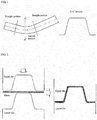
- FIG. 1 When a product having generally a hat type or a channel type cross-sectional shape and being curved in a longitudinal direction as shown in FIG. 1 is press formed from a flat blank with a press forming mold comprised of an upper die and a lower die of a shape corresponding to a product shape as shown in FIG. 1 is press formed from a flat blank with a press forming mold comprised of an upper die and a lower die of a shape corresponding to a product shape as shown in FIG.
- tensile stress is generated in an outside of a curved portion in the longitudinal direction of the product and compression stress is generated in an inside thereof and hence residual bending moment is generated so as to mitigate a difference between these stresses, whereby there is generated a phenomenon called as camber back that a radius of curvature of a curved portion after the releasing from the mold as shown by a solid line becomes larger with respect to a formed shape shown by dotted lines at a bottom dead point of the upper die as shown in FIG. 3 .
- This phenomenon is a type of spring back deformation, and a return quantity thereof becomes larger in a steel sheet as a strength of the steel sheet becomes higher.
- a method for reducing camber back is considered a method wherein compression stress is applied to a portion of generating tensile stress in the outside of the curved portion to decrease residual bending moment.
- the invention is concerned with a press forming method and a press forming apparatus, or a press forming mold capable of applying compression stress to only a portion requiring application of compression stress, or a curved portion.
- FIG. 4 is a longitudinal section view schematically illustrating a construction of a press forming mold in an embodiment of the press forming apparatus according to the invention for carrying out an embodiment of the press forming method and the method for manufacturing a pressed product according to the invention, wherein FIG. 4(a), FIG. 4(b) and FIG. 4(c) show a state of a blank before forming, during forming and at the end of forming (at bottom dead point of upper die), respectively.
- the press forming mold of this embodiment forms a product having a curved portion in its intermediate portion and straight portions adjacent to both sides thereof along a longitudinal direction and a hat type cross-sectional shape as a side shape is shown in a left side of FIG. 1 and an A-A' section (cross-section) is shown in a right side thereof. Therefore, a cross-sectional shape of a forming portion in an upper die and a lower die constituting the press forming mold of this embodiment has a hat form corresponding to the cross-sectional shape of the product as shown in FIG. 2 .
- the press forming mold of this embodiment comprises opposite upper die and lower die and a blank setting base adjacent to the lower die.
- the lower die is divided into a lower die segment 3 corresponding to a curved portion of a product and lower die segments 1, 2 corresponding to straight portions adjacent to both sides of the curved portion of the product.
- the lower die segments 1, 2 corresponding to the straight portions are held by cushion pins connected to a cushion device of a usual press machine (not shown) mounting the above press forming mold at a state capable of pushing in association with reaction force.
- the lower die segments 1, 2 have a structure supported by the cushion pin(s), but may have a structure supported by a metal spring, a gas spring or the like.
- the press forming mold of this embodiment is operated as follows. At first, the blank setting bases and the lower die segment 3 are attached to a bolster of the press machine through a base plate (not shown) and the upper die is attached to a slide of the press machine, wherein the upper die can be elevated to the lower die segments 1, 2, 3 by an elevating actuation of the slide. Also, the lower die segments 1, 2 are uplifted and supported by cushion pins connected to a cushion device of the press machine and passing through the bolster. After the upper die is elevated upward by the slide, a flat blank is placed on the blank setting bases as shown in FIG. 4(a) .
- a face of the blank setting base placing the blank is preferable to be declined viewing from a side in order to facilitate pushing of the blank to the blank setting base.
- a longitudinal length L of the blank used is longer than a longitudinal length L0 along a curve of a bottom in a hat shape of a product.
- the length is too long, buckling is caused, so that it is L0 ⁇ L ⁇ 1.05 ⁇ L0.
- the upper die is lowered by the slide of the press machine to push the blank between the blank setting bases.
- both end portions of the blank are formed by the upper die and the lower die segments 1 and 2 so as to correspond to straight portions of the product as shown in FIG. 4(b) .
- a material surplus in the longitudinal direction is generated in an intermediate portion of the blank (portion above the lower die segment 3) corresponding to a curved portion of the product.
- the intermediate portion of the blank generating the material surplus is formed into a curved portion of the product by the upper die and the lower die segment 3 while clipping the both end portions of the blank with the upper die and the lower die segments 1 and 2.
- compression stress can be applied to the curved portion of the product to be formed in the longitudinal direction.
- FIG. 5 is a longitudinal section view schematically illustrating a construction of a press forming mold having a divided upper die different from the previous embodiment in another embodiment of the press forming apparatus according to the invention for carrying out another embodiment of the press forming method and the method for manufacturing a pressed product according to the invention, wherein FIG.5(a), FIG.5(b) and FIG.5(c) show a state of a blank before forming, during forming and at the end of forming (at bottom dead point of upper die), respectively.
- the press forming mold of this embodiment has the same fundamental thinking as described in the previous embodiment, but has a structure that the upper die is divided into upper die segments 1, 2 corresponding to the straight portions of the product and upper die segment 3 corresponding to the curved portion of the product and a metal spring or a gas spring holding the material at a state capable of pushing in association with reaction force is incorporated into each of the upper die segments 1, 2 corresponding to the straight portions of the product.
- the portions of the blank corresponding to the straight portions of the product are not necessary to be completely formed at an initial stage of the forming. It is enough to restrain the portions corresponding to the straight portions during the forming of the portion of the blank corresponding to the curved portion of the product.
- the cross-sectional shape of the product may be a channel type having no flange portion instead of the hat type having flange portions.
- the lower die segments corresponding to the straight portions of the product may be held by a metal spring, a gas spring or the like instead of the cushion device.
- compression stress in the longitudinal direction is applied to the portion of the blank corresponding to the curved portion of the product to be formed, so that tensile stress in the longitudinal direction is not retained substantially or completely in the curved portion of the formed product, or the pressed product by offsetting with the above compression stress after the press forming and hence the occurrence of camber back resulted from tensile stress in the longitudinal direction can be prevented effectively even in products being low in the wall height and small in the section stiffness, and it is possible to form a product having a hat type cross-sectional shape or a channel type cross-sectional shape and a longitudinal curved shape comprised of a curved portion in its intermediate part and straight portions adjacent to both sides thereof in a good dimensional accuracy without restricting the product shape.
Abstract
Description
- This invention relates to a press forming of a metal plate into a product of a hat type or channel type cross-sectional shape, and more particularly to a press forming method for a product having a longitudinally curved shape viewing from a vertical wall direction (from a side) and a method for manufacturing the same as a pressed product as well as a press forming apparatus, or a press forming mold used in these methods.
- In the press forming of the metal plate, spring-back deformation is caused in a pressed product released from the mold due to elastic recovery, which comes into problem on a dimensional accuracy of a product. Recently, the use of thin-walled, high-tensile steel sheets or aluminum alloy plates is particularly increasing in automobile constructional products for achieving weight reduction of a vehicle body. These materials are large in the spring-back deformation, so that defect of the dimensional accuracy is actualized.
- The defect of the dimensional accuracy in the cross-section of the product includes an angle change of a vertical wall, a wall warp, and distortion, bending and camber-back as a whole of the product. There are proposed a great number of countermeasures against each of these defect phenomena. The camber-back is a bad phenomenon that a curved shape in a product having a curve in its longitudinal direction is returned back after press forming, or a radius of curvature is made larger as compared to a target radius of curvature. The camber back is significantly caused in products being low in the wall height and small in the section stiffness.
- As a countermeasure for the camber back in a product having a hat type cross-sectional shape, for example,
Patent Document 1 discloses a technique of suppressing the camber back by making a height of a vertical wall smaller than a difference between a radius of curvature in a hat head portion and a radius of curvature in a flange portion. However, this technique cannot be applied to all of product shapes because there is a restriction in the product shape. - Also,
Patent Document 2 discloses a technique of suppressing the camber back by deforming a top portion of an arc-like curved part into a concave shape in an anti-bulging direction under pressure on the way of the press forming to decrease residual tensile stress in the top portion. In this technique, however, the concave shape is formed in the top portion of the arc-like curved part as
shown in examples, so that the product shape is restricted but also a shape-correcting process such as subsequent restriking step is required when the concave shape is unnecessary. -
- Patent Document 1:
JP-A-2013-063462 - Patent Document 2:
JP-A-2010-207906 - In the conventional techniques, it is obliged to restrict the product shape for suppressing the camber back as mentioned above. Therefore, the invention is to solve the above task and provide a press forming method capable of suppressing camber back in products having a hat type or channel type cross-sectional shape and a longitudinally curved shape viewing from a vertical wall direction (from a side) and a method for manufacturing a pressed product as well as a press forming apparatus, or a press forming mold used in these methods.
- The inventors have made various studies in order to achieve the above object and found out a press forming method and a press forming apparatus wherein a blank having a length somewhat longer than a longitudinal length along a curved portion of a product shape is used and compression stress is introduced into only a curvature portion being a main factor of camber back and obtained a knowledge that the camber back can be largely suppressed by press forming with them.
- That is, the invention lies in a method for press forming a product having a hat type or channel type cross-sectional shape and a longitudinal shape with a curved portion in its intermediate portion and straight portions adjacent to both sides thereof from a blank, wherein both ends of a blank having a length longer than a length along a longitudinal direction of a product to be formed are first approached to each other up to a distance between both ends of the product to be formed;
portions of the blank corresponding to the straight portions of the product to be formed are restrained while being press formed to a hat type or channel type cross-sectional shape prior to a portion of the blank corresponding to the curved portion of the product to be formed at an approached state of the both ends to thereby leave a surplus in a length of the portion of the blank corresponding to the curved portion of the product to be formed as compared to a length of the curved portion;
the portion of the blank corresponding to the curved portion of the product to be formed is press formed to a longitudinal curved shape at a state of leaving the surplus while forming the hat type or channel type cross-sectional shape to thereby apply a longitudinal compression stress to the portion of the blank corresponding to the curved portion of the product to be formed. - Also, the invention lies in a method for manufacturing a pressed product by press forming a product having a hat type or channel type cross-sectional shape and a longitudinal shape with a curved portion in its intermediate portion and straight portions adjacent to both sides thereof from a blank, wherein both ends of a blank having a length longer than a length along a longitudinal direction of a product to be formed are first approached to each other up to a distance between both ends of the product to be formed;
portions of the blank corresponding to the straight portions of the product to be formed are restrained while being press formed to a hat type or channel type cross-sectional shape prior to a portion of the blank corresponding to the curved portion of the product to be formed at an approached state of the both ends to thereby leave a surplus in a length of the portion of the blank corresponding to the curved portion of the product to be formed as compared to a length of the curved portion;
the portion of the blank corresponding to the curved portion of the product to be formed is press formed to a longitudinal curved shape at a state of leaving the surplus while forming the hat type or channel type cross-sectional shape to thereby apply a longitudinal compression stress to the portion of the blank corresponding to the curved portion of the product to be formed. - Furthermore, the invention lies in a press forming apparatus used in press forming of a product having a hat type or channel type cross-sectional shape and a longitudinal shape with a curved portion in its intermediate portion and straight portions adjacent to both sides thereof from a blank, characterized by comprising opposite upper die and lower die, wherein the lower die comprises a blank holding part for positioning both ends of a blank having a length longer than a length along a longitudinal direction of a product to be formed at a state of approaching them to each other up to a distance between both ends of the product to be formed;
one of the upper die and the lower die has a forming part of a shape corresponding to a shape of the product to be formed;
the other of the upper die and the lower die has a forming part of a shape corresponding to the shape of the product to be formed and a forming part divided into a curved portion and straight portions adjacent to both sides thereof;
the straight portions of the forming part are approached to the former one of the upper die and the lower die as compared to the curved portion of the forming part so as to start the forming of the blank prior to the curved portion of the forming part and held at a state capable of of pushing in association with reaction force. - According to the press forming method and method for manufacturing a pressed product according to the invention, when a product having a hat type or channel type cross-sectional shape and a longitudinal shape with a curved portion in its intermediate portion and straight portions adjacent to both sides thereof is press formed from a blank, both ends of a blank having a length longer than a length along a longitudinal direction of a product to be formed are first approached to each other up to a distance between both ends of the product to be formed, and thereafter portions of the blank corresponding to the straight portions of the product to be formed are restrained while being press formed to a hat type or channel type cross-sectional shape prior to a portion of the blank corresponding to the curved portion of the product to be formed at an approached state of the both ends to thereby leave a surplus in a length of the portion of the blank corresponding to the curved portion of the product to be formed as compared to a length of the curved portion, and then the portion of the blank corresponding to the curved portion of the product to be formed is press formed to a longitudinal curved shape at a state of leaving the surplus while forming the hat type or channel type cross-sectional shape to thereby apply a longitudinal compression stress to the portion of the blank corresponding to the curved portion of the product to be formed, so that tensile stress in the longitudinal direction of the curved portion of the formed product is not retained substantially or fully after the press forming by offsetting with the compression stress and hence the occurrence of camber back resulting from the tensile stress in the longitudinal direction can be prevented effectively even in products being low in the wall height and small in the section stiffness, and it is possible to form a product having a hat type or channel type cross-sectional shape and a longitudinal shape with a curved portion in its intermediate portion and straight portions adjacent to both sides thereof in a good dimension accuracy without restricting the product shape.
- In the press forming apparatus according to the invention, the blank holding part of the lower die in the opposite upper die and lower die positions the both ends of the blank having a length longer than a length along a longitudinal direction of a product to be formed at a state of approaching them to each other up to a distance between both ends of the product to be formed, and a product having a hat type or channel type cross-sectional shape and a longitudinal shape with a curved portion in its intermediate portion and straight portions adjacent to both sides thereof is press formed from the blank having the positioned both ends by cooperation of the lower die and upper die through approach movement between the forming part of the shape in one of them and the forming part of the shape in the other corresponding to the shape of the product to be formed to each other.
- In this case, the forming part of the latter one of the upper die and the lower die is divided into a curved portion and straight portions adjacent to both sides thereof, and the straight portions are approached to the former one of the upper die and lower die as compared to the curved portion of the forming part and held at a state capable of pushing in association with reaction force and co-worked with the straight portion of the forming part in the former one of the upper die and lower die to start the forming of the blank prior to the curved portion of the forming part, whereby the portions of the blank corresponding to the straight portions of the product to be formed is restrained while being press formed to a hat type or channel type cross-sectional shape to thereby leave a surplus in the length of the portion of the blank corresponding to the curved portion of the product to be formed as compared to the length of the curved portion. Then, the curved portion of the forming part in the latter one of the lower die and upper die is co-worked with the curved portion of the forming part in the former one of the upper die and lower die, whereby the portion of the blank corresponding to the curved portion of the product to be formed is press formed to a longitudinal curved shape while forming the hat type or channel type cross-sectional shape to apply compression stress in the longitudinal direction to such a portion of the blank.
- The holding capable of pushing in association with reaction force includes a case of holding with an elastic member such as metal spring, rubbery elastomer or the like and a case that the blank is held with a hydraulic, pneumatic or hydraulic-pneumatic cushion device of a press machine, a gas spring or the like and pushed to a backward limit position associated with moving down of the upper die while applying reaction force to pushing force of the opposing die and returned to original position associated with moving up of the upper die.
- According to the press forming apparatus of the invention, therefore, compression stress in the longitudinal direction is applied to the portion of the blank corresponding to the curved portion of the product to be formed, so that tensile stress in the longitudinal direction of the curved portion of the formed product after the press forming is not retained substantially or completely by offsetting with the compression stress, and hence the occurrence of camber back resulted from the tensile stress in the longitudinal direction can be prevented effectively even in the products being low in the wall height and small in the section stiffness, and it is possible to form a product having a hat type or channel type cross-sectional shape and a longitudinal shape with a curved portion in its intermediate portion and straight portions adjacent to both sides thereof in a good dimension accuracy without restricting the product shape.
- Moreover, in the press forming method and the method for manufacturing a pressed product as well as the press forming apparatus according to the invention, when the longitudinal length L of the blank exceeds 1.05 times of a length L0 along the longitudinal direction of the product to be formed, the possibility of buckling due to compression stress becomes higher, so that the longitudinal length L of the blank is preferable to be larger than the length L0 along the longitudinal direction of the product to be formed and smaller than 1.05×L0 or equal to 1.05×L0, i.e. L0 < L ≤ 1.05×L0.
-
-
FIG. 1 is a side view schematically illustrating a typical shape of a product applied by the press forming method and the method for manufacturing a pressed product as well as the press forming apparatus according to the invention and a cross-section view at a position A-A' thereof. -
FIG. 2 is a cross-section view schematically illustrating an example of the conventional press forming mold for press forming the above product shape. -
FIG. 3 is a view schematically illustrating camber back of a curved product press formed by the conventional method with the above press forming mold. -
FIG. 4 is a longitudinal section view schematically illustrating a construction of a press forming mold in an embodiment of the press forming apparatus according to the invention for carrying out an embodiment of the press forming method and the method for manufacturing a pressed product according to the invention, wherein (a), (b) and (c) show a state of a blank before forming, during forming and at the end of forming (at bottom dead point of upper die), respectively. -
FIG. 5 is a longitudinal section view schematically illustrating a construction of a press forming mold in another embodiment of the press forming apparatus according to the invention for carrying out another embodiment of the press forming method and the method for manufacturing a pressed product according to the invention, wherein (a), (b) and (c) show a state of a blank before forming, during forming and at the end of forming (at bottom dead point of upper die), respectively. - When a product having generally a hat type or a channel type cross-sectional shape and being curved in a longitudinal direction as shown in
FIG. 1 is press formed from a flat blank with a press forming mold comprised of an upper die and a lower die of a shape corresponding to a product shape as shown inFIG. 2 , tensile stress is generated in an outside of a curved portion in the longitudinal direction of the product and compression stress is generated in an inside thereof and hence residual bending moment is generated so as to mitigate a difference between these stresses, whereby there is generated a phenomenon called as camber back that a radius of curvature of a curved portion after the releasing from the mold as shown by a solid line becomes larger with respect to a formed shape shown by dotted lines at a bottom dead point of the upper die as shown inFIG. 3 . This phenomenon is a type of spring back deformation, and a return quantity thereof becomes larger in a steel sheet as a strength of the steel sheet becomes higher. - As a method for reducing camber back is considered a method wherein compression stress is applied to a portion of generating tensile stress in the outside of the curved portion to decrease residual bending moment. The invention is concerned with a press forming method and a press forming apparatus, or a press forming mold capable of applying compression stress to only a portion requiring application of compression stress, or a curved portion.
- An embodiment of the invention will be described in detail with reference to the drawings below.
FIG. 4 is a longitudinal section view schematically illustrating a construction of a press forming mold in an embodiment of the press forming apparatus according to the invention for carrying out an embodiment of the press forming method and the method for manufacturing a pressed product according to the invention, whereinFIG. 4(a), FIG. 4(b) and FIG. 4(c) show a state of a blank before forming, during forming and at the end of forming (at bottom dead point of upper die), respectively. - The press forming mold of this embodiment forms a product having a curved portion in its intermediate portion and straight portions adjacent to both sides thereof along a longitudinal direction and a hat type cross-sectional shape as a side shape is shown in a left side of
FIG. 1 and an A-A' section (cross-section) is shown in a right side thereof. Therefore, a cross-sectional shape of a forming portion in an upper die and a lower die constituting the press forming mold of this embodiment has a hat form corresponding to the cross-sectional shape of the product as shown inFIG. 2 . - The press forming mold of this embodiment comprises opposite upper die and lower die and a blank setting base adjacent to the lower die. The lower die is divided into a
lower die segment 3 corresponding to a curved portion of a product and lowerdie segments lower die segments FIG. 4 , thelower die segments - The press forming mold of this embodiment is operated as follows. At first, the blank setting bases and the
lower die segment 3 are attached to a bolster of the press machine through a base plate (not shown) and the upper die is attached to a slide of the press machine, wherein the upper die can be elevated to thelower die segments lower die segments FIG. 4(a) . - A face of the blank setting base placing the blank is preferable to be declined viewing from a side in order to facilitate pushing of the blank to the blank setting base. And also, in order to apply compression stress to the blank, it is necessary that a longitudinal length L of the blank used is longer than a longitudinal length L0 along a curve of a bottom in a hat shape of a product. However, if the length is too long, buckling is caused, so that it is L0 < L ≤ 1.05×L0.
- After the blank is placed on the blank setting base, the upper die is lowered by the slide of the press machine to push the blank between the blank setting bases. Thereafter, both end portions of the blank are formed by the upper die and the
lower die segments FIG. 4(b) . In this regard, a material surplus in the longitudinal direction is generated in an intermediate portion of the blank (portion above the lower die segment 3) corresponding to a curved portion of the product. Then, as shown inFIG. 4(c) , the intermediate portion of the blank generating the material surplus is formed into a curved portion of the product by the upper die and thelower die segment 3 while clipping the both end portions of the blank with the upper die and thelower die segments - According to the press forming mold and the press forming method of this embodiment using the same and the method for manufacturing a pressed product according to the invention, therefore, compression stress in the longitudinal direction is applied to the portion of the blank corresponding to the curved portion of the product to be formed, so that tensile stress in the longitudinal direction is not retained substantially or completely in the curved portion of the formed product, or the pressed product by offsetting with the above compression stress after the press forming and hence the occurrence of camber back resulted from tensile stress in the longitudinal direction can be prevented effectively even in products being low in the wall height and small in the section stiffness, and it is possible to form a product having a hat type cross-sectional shape and a longitudinal curved shape comprised of a curved portion in its intermediate part and straight portions adjacent to both sides thereof in a good dimensional accuracy without restricting the product shape.
-
FIG. 5 is a longitudinal section view schematically illustrating a construction of a press forming mold having a divided upper die different from the previous embodiment in another embodiment of the press forming apparatus according to the invention for carrying out another embodiment of the press forming method and the method for manufacturing a pressed product according to the invention, whereinFIG.5(a), FIG.5(b) and FIG.5(c) show a state of a blank before forming, during forming and at the end of forming (at bottom dead point of upper die), respectively. - The press forming mold of this embodiment has the same fundamental thinking as described in the previous embodiment, but has a structure that the upper die is divided into
upper die segments upper die segment 3 corresponding to the curved portion of the product and a metal spring or a gas spring holding the material at a state capable of pushing in association with reaction force is incorporated into each of theupper die segments - When a product having a shape as shown in
FIG. 1 is press formed with the press forming mold of this embodiment, after the press forming mold is attached to a press machine similarly in the previous embodiment, a flat blank is placed on blank setting bases as shown inFIG. 5(a) and then the blank is pushed between the blank setting bases with theupper die segments upper die segments FIG. 5(b) . In this regard, a material surplus in the longitudinal direction is generated in an intermediate portion of the blank corresponding to the curved portion of the product. Thereafter, as shown inFIG. 5(c) , the intermediate portion is formed by the lower die and theupper die segment 3, whereby compression stress can be applied to the curved portion of the product to be formed in the longitudinal direction. - According to the press forming mold and the press forming method of this embodiment using the same and the method for manufacturing a pressed product according to the invention, therefore, compression stress in the longitudinal direction is applied to the portion of the blank corresponding to the curved portion of the product to be formed, so that tensile stress in the longitudinal direction is not retained substantially or completely in the curved portion of the formed product, or the pressed product by offsetting with the above compression stress after the press forming and hence the occurrence of camber back resulted from tensile stress in the longitudinal direction can be prevented effectively even in products being low in the wall height and small in the section stiffness, and it is possible to form a product having a hat type cross-sectional shape and a longitudinal curved shape comprised of a curved portion in its intermediate part and straight portions adjacent to both sides thereof in a good dimensional accuracy without restricting the product shape.
- In the embodiments shown in
FIGs. 4 and5 , the portions of the blank corresponding to the straight portions of the product are not necessary to be completely formed at an initial stage of the forming. It is enough to restrain the portions corresponding to the straight portions during the forming of the portion of the blank corresponding to the curved portion of the product. - Although the above is described with reference to the illustrated examples, the invention is not limited to these examples and may be properly modified within a scope described in claims, if necessary. For example, the cross-sectional shape of the product may be a channel type having no flange portion instead of the hat type having flange portions.
- Even if the lower die is divided in the press forming mold, the lower die segments corresponding to the straight portions of the product may be held by a metal spring, a gas spring or the like instead of the cushion device.
- Thus, according to the press forming method and the method for manufacturing a pressed product as well as the press forming apparatus according to the invention, compression stress in the longitudinal direction is applied to the portion of the blank corresponding to the curved portion of the product to be formed, so that tensile stress in the longitudinal direction is not retained substantially or completely in the curved portion of the formed product, or the pressed product by offsetting with the above compression stress after the press forming and hence the occurrence of camber back resulted from tensile stress in the longitudinal direction can be prevented effectively even in products being low in the wall height and small in the section stiffness, and it is possible to form a product having a hat type cross-sectional shape or a channel type cross-sectional shape and a longitudinal curved shape comprised of a curved portion in its intermediate part and straight portions adjacent to both sides thereof in a good dimensional accuracy without restricting the product shape.
Claims (7)
- A method for press forming a product having a hat type or channel type cross-sectional shape and a longitudinal shape with a curved portion in its intermediate portion and straight portions adjacent to both sides thereof from a blank, wherein both ends of a blank having a length longer than a length along a longitudinal direction of a product to be formed are first approached to each other up to a distance between both ends of the product to be formed;
portions of the blank corresponding to the straight portions of the product to be formed are restrained while being press formed to a hat type or channel type cross-sectional shape prior to a portion of the blank corresponding to a curved portion of the product to be formed at an approached state of the both ends to thereby leave a surplus in a length of the portion of the blank corresponding to the curved portion of the product to be formed as compared to a length of the curved portion;
the portion of the blank corresponding to the curved portion of the product to be formed is press formed to a longitudinal curved shape at a state of leaving the surplus while forming the hat type or channel type cross-sectional shape to thereby apply a longitudinal compression stress to the portion of the blank corresponding to curved portion of the product to be formed. - A method for manufacturing a pressed product by press forming a product having a hat type or channel type cross-sectional shape and a longitudinal shape with a curved portion in its intermediate portion and straight portions adjacent to both sides thereof from a blank, wherein both ends of a blank having a length longer than a length along a longitudinal direction of a product to be formed are first approached to each other up to a distance between both ends of the product to be formed;
portions of the blank corresponding to the straight portions of the product to be formed are restrained while being press formed to a hat type or channel type cross-sectional shape prior to a portion of the blank corresponding to a curved portion of the product to be formed at an approached state of the both ends to thereby leave a surplus in a length of the portion of the blank corresponding to the curved portion of the product to be formed as compared to a length of the curved portion;
the portion of the blank corresponding to the curved portion of the product to be formed is press formed to a longitudinal curved shape at a state of leaving the surplus while forming the hat type or channel type cross-sectional shape to thereby apply a longitudinal compression stress to the portion of the blank corresponding to the curved portion of the product to be formed. - The method according to claim 1 or 2, wherein a longitudinal length L of the blank is larger than a length L0 along the longitudinal direction of the product to be formed and smaller than 1.05×L0 or equal to 1.05×L0.
- A press forming apparatus used in press forming of a product having a hat type or channel type cross-sectional shape and a longitudinal shape with a curved portion in its intermediate portion and straight portions adjacent to both sides thereof from a blank, characterized by comprising opposite upper die and lower die, wherein the lower die comprises a blank holding part for positioning both ends of a blank having a length longer than a length along a longitudinal direction of a product to be formed at a state of approaching them to each other up to a distance between both ends of the product to be formed;
one of the upper die and the lower die has a forming part of a shape corresponding to a shape of the product to be formed;
the other of the upper die and the lower die has a forming part of a shape corresponding to the shape of the product to be formed and a forming part divided into a curved portion and straight portions adjacent to both sides thereof;
the straight portions of the forming part are approached to the former one of the upper die and the lower die as compared to the curved portion of the forming part so as to start the forming of the blank prior to the curved portion of the forming part and held at a state capable of of pushing in association with reaction force. - The press forming apparatus according to claim 4, wherein the upper die has a forming part of a shape corresponding to a shape of the product to be formed;
the lower die has a forming part of a shape corresponding to the shape of the product to be formed and a forming part divided into a curved portion and straight portions adjacent to both sides thereof;
the straight portions in the forming part of the lower die are approached to the upper die as compared to the curved portion in the forming part of the lower die so as to start the forming of the blank prior to the curved portion in the forming part of the lower die and held at a state capable of of pushing with a cushion device. - The press forming apparatus according to claim 4, wherein the lower die has a forming part of a shape corresponding to a shape of the product to be formed;
the upper die has a forming part of a shape corresponding to the shape of the product to be formed and a forming part divided into a curved portion and straight portions adjacent to both sides thereof;
the straight portions in the forming part of the upper die are approached to the lower die as compared to the curved portion in the forming part of the upper die so as to start the forming of the blank prior to the curved portion in the forming part of the upper die and held at a state capable of of pushing with an elastic member. - The press forming apparatus according to any one of claims 4 to 6, wherein a longitudinal length L of the blank is larger than a length L0 along the longitudinal direction of the product to be formed and smaller than 1.05×L0 or equal to 1.05×L0.
Applications Claiming Priority (2)
| Application Number | Priority Date | Filing Date | Title |
|---|---|---|---|
| JP2014033007 | 2014-02-24 | ||
| PCT/JP2015/054091 WO2015125723A1 (en) | 2014-02-24 | 2015-02-16 | Press-forming method, method for manufacturing pressed product, and press-forming device |
Publications (3)
| Publication Number | Publication Date |
|---|---|
| EP3112041A1 true EP3112041A1 (en) | 2017-01-04 |
| EP3112041A4 EP3112041A4 (en) | 2017-08-23 |
| EP3112041B1 EP3112041B1 (en) | 2020-09-02 |
Family
ID=53878227
Family Applications (1)
| Application Number | Title | Priority Date | Filing Date |
|---|---|---|---|
| EP15752150.1A Active EP3112041B1 (en) | 2014-02-24 | 2015-02-16 | Press-forming method and press-forming device |
Country Status (7)
| Country | Link |
|---|---|
| US (1) | US10226807B2 (en) |
| EP (1) | EP3112041B1 (en) |
| JP (1) | JP5812312B1 (en) |
| KR (1) | KR101867744B1 (en) |
| CN (1) | CN106029248B (en) |
| MX (1) | MX370432B (en) |
| WO (1) | WO2015125723A1 (en) |
Families Citing this family (6)
| Publication number | Priority date | Publication date | Assignee | Title |
|---|---|---|---|---|
| US11014139B2 (en) * | 2015-04-22 | 2021-05-25 | Nippon Steel Corporation | Pressed component manufacturing method, pressed component, and pressing apparatus |
| JP6448587B2 (en) * | 2016-08-10 | 2019-01-09 | 東亜工業株式会社 | Hot press apparatus and hot press method |
| JP2018061979A (en) * | 2016-10-13 | 2018-04-19 | 三恵工業株式会社 | Pipe manufacturing method and press device used therein |
| JP6500927B2 (en) * | 2017-03-28 | 2019-04-17 | Jfeスチール株式会社 | Press forming apparatus and method of manufacturing press formed article |
| JP6708182B2 (en) * | 2017-08-07 | 2020-06-10 | Jfeスチール株式会社 | Method for manufacturing press-formed products |
| JP6760551B1 (en) * | 2019-05-20 | 2020-09-23 | Jfeスチール株式会社 | Manufacturing method of pressed parts and mold for shape correction |
Family Cites Families (14)
| Publication number | Priority date | Publication date | Assignee | Title |
|---|---|---|---|---|
| US6276185B1 (en) * | 1999-12-09 | 2001-08-21 | General Motors Corporation | Flow lock bead control apparatus and method for drawing high strength steel |
| JP4568077B2 (en) | 2004-10-19 | 2010-10-27 | 新日本製鐵株式会社 | Press mold with excellent shape freezing |
| JP4612494B2 (en) * | 2005-07-21 | 2011-01-12 | 新日本製鐵株式会社 | Method for forming cross-section hat-shaped member with excellent shape freezing property |
| JP4709659B2 (en) * | 2006-02-23 | 2011-06-22 | 新日本製鐵株式会社 | Multi-stage press forming method with excellent shape freezing |
| JP4757820B2 (en) | 2007-03-14 | 2011-08-24 | 新日本製鐵株式会社 | Multi-stage press forming method with excellent shape freezing |
| JP5020858B2 (en) | 2008-02-27 | 2012-09-05 | 新日本製鐵株式会社 | Metal cross-section hat-shaped member having a bent portion in a plane in the longitudinal direction of the member and press forming method thereof |
| JP4907590B2 (en) | 2008-04-01 | 2012-03-28 | 新日本製鐵株式会社 | Metal cross-section hat-shaped member having a bent portion outside the plane in the longitudinal direction of the member, and press forming method thereof |
| JP5470812B2 (en) | 2008-11-20 | 2014-04-16 | 日産自動車株式会社 | Method and apparatus for manufacturing a press-molded product, and press-molded product |
| JP5353329B2 (en) | 2009-03-12 | 2013-11-27 | 日産自動車株式会社 | Press molding method and press molding apparatus excellent in shape freezing property, and manufacturing method of the press molding apparatus |
| WO2011148880A1 (en) * | 2010-05-25 | 2011-12-01 | 新日本製鐵株式会社 | Method for forming metal member having excellent shape freezing properties |
| JP2012218061A (en) * | 2011-04-13 | 2012-11-12 | Honda Motor Co Ltd | Press molding apparatus |
| JP5808940B2 (en) * | 2011-05-02 | 2015-11-10 | 本田技研工業株式会社 | Press molding method and apparatus |
| JP5987385B2 (en) | 2011-08-30 | 2016-09-07 | Jfeスチール株式会社 | Press molding method of hat-shaped member curved in longitudinal direction |
| JP6834079B2 (en) * | 2016-06-30 | 2021-02-24 | 日本製紙クレシア株式会社 | Pants type absorbent goods |
-
2015
- 2015-02-16 KR KR1020167022137A patent/KR101867744B1/en active IP Right Grant
- 2015-02-16 JP JP2015530218A patent/JP5812312B1/en active Active
- 2015-02-16 WO PCT/JP2015/054091 patent/WO2015125723A1/en active Application Filing
- 2015-02-16 CN CN201580010003.6A patent/CN106029248B/en not_active Expired - Fee Related
- 2015-02-16 MX MX2016010670A patent/MX370432B/en active IP Right Grant
- 2015-02-16 EP EP15752150.1A patent/EP3112041B1/en active Active
- 2015-02-16 US US15/120,557 patent/US10226807B2/en not_active Expired - Fee Related
Also Published As
| Publication number | Publication date |
|---|---|
| CN106029248B (en) | 2018-03-06 |
| JPWO2015125723A1 (en) | 2017-03-30 |
| MX370432B (en) | 2019-12-13 |
| WO2015125723A1 (en) | 2015-08-27 |
| US20170014886A1 (en) | 2017-01-19 |
| KR20160108498A (en) | 2016-09-19 |
| EP3112041A4 (en) | 2017-08-23 |
| CN106029248A (en) | 2016-10-12 |
| EP3112041B1 (en) | 2020-09-02 |
| US10226807B2 (en) | 2019-03-12 |
| JP5812312B1 (en) | 2015-11-11 |
| KR101867744B1 (en) | 2018-06-15 |
| MX2016010670A (en) | 2016-11-08 |
Similar Documents
| Publication | Publication Date | Title |
|---|---|---|
| EP3112041B1 (en) | Press-forming method and press-forming device | |
| JP5664810B1 (en) | Press forming method and apparatus | |
| JP5808940B2 (en) | Press molding method and apparatus | |
| KR101821074B1 (en) | Production method for press-molded body, and press molding device | |
| CN109562427B (en) | Method for producing press-molded article | |
| JP6359171B2 (en) | Press forming method | |
| EP2878392A1 (en) | Press-forming mold and method for manufacturing press-formed product | |
| JP5626088B2 (en) | Press molding die and press molding method | |
| JP2009255117A (en) | Press-forming method excellent in shape fixability and apparatus therefor | |
| KR20170010832A (en) | Method for manufacturing press-molded article, and press-molded article | |
| JP4920649B2 (en) | Multi-stage press forming method with excellent shape freezing | |
| JP2006305627A (en) | Method for forming curve-shaped channel member | |
| JP6083390B2 (en) | Press forming method | |
| US10413956B2 (en) | Press forming method and method of manufacturing press formed product | |
| JP6075333B2 (en) | Press forming method and apparatus | |
| JP5031703B2 (en) | Multi-stage press forming method with excellent shape freezing | |
| JP5949856B2 (en) | Press forming method and apparatus | |
| EP3778053A1 (en) | Designing method for press-molded article, press-molding die, press-molded article, and production method for press-molded article | |
| JP2017042773A (en) | Press molding method | |
| JP6330747B2 (en) | Press molding die and press molding method | |
| JP6036768B2 (en) | Press forming method | |
| KR101591874B1 (en) | Double cross pad of upper die for compensating deformation after stamping automotive structure panel and method thereof | |
| JP2005254279A (en) | Press die | |
| JP6202019B2 (en) | Press forming method | |
| JP7352123B1 (en) | Manufacturing method of press molded products |
Legal Events
| Date | Code | Title | Description |
|---|---|---|---|
| STAA | Information on the status of an ep patent application or granted ep patent |
Free format text: STATUS: THE INTERNATIONAL PUBLICATION HAS BEEN MADE |
|
| PUAI | Public reference made under article 153(3) epc to a published international application that has entered the european phase |
Free format text: ORIGINAL CODE: 0009012 |
|
| STAA | Information on the status of an ep patent application or granted ep patent |
Free format text: STATUS: REQUEST FOR EXAMINATION WAS MADE |
|
| 17P | Request for examination filed |
Effective date: 20160822 |
|
| AK | Designated contracting states |
Kind code of ref document: A1 Designated state(s): AL AT BE BG CH CY CZ DE DK EE ES FI FR GB GR HR HU IE IS IT LI LT LU LV MC MK MT NL NO PL PT RO RS SE SI SK SM TR |
|
| AX | Request for extension of the european patent |
Extension state: BA ME |
|
| DAX | Request for extension of the european patent (deleted) | ||
| A4 | Supplementary search report drawn up and despatched |
Effective date: 20170724 |
|
| RIC1 | Information provided on ipc code assigned before grant |
Ipc: B21D 22/26 20060101AFI20170718BHEP Ipc: B21D 24/00 20060101ALI20170718BHEP |
|
| GRAP | Despatch of communication of intention to grant a patent |
Free format text: ORIGINAL CODE: EPIDOSNIGR1 |
|
| STAA | Information on the status of an ep patent application or granted ep patent |
Free format text: STATUS: GRANT OF PATENT IS INTENDED |
|
| INTG | Intention to grant announced |
Effective date: 20200406 |
|
| GRAS | Grant fee paid |
Free format text: ORIGINAL CODE: EPIDOSNIGR3 |
|
| GRAA | (expected) grant |
Free format text: ORIGINAL CODE: 0009210 |
|
| STAA | Information on the status of an ep patent application or granted ep patent |
Free format text: STATUS: THE PATENT HAS BEEN GRANTED |
|
| AK | Designated contracting states |
Kind code of ref document: B1 Designated state(s): AL AT BE BG CH CY CZ DE DK EE ES FI FR GB GR HR HU IE IS IT LI LT LU LV MC MK MT NL NO PL PT RO RS SE SI SK SM TR |
|
| REG | Reference to a national code |
Ref country code: GB Ref legal event code: FG4D |
|
| REG | Reference to a national code |
Ref country code: AT Ref legal event code: REF Ref document number: 1308239 Country of ref document: AT Kind code of ref document: T Effective date: 20200915 Ref country code: CH Ref legal event code: EP |
|
| REG | Reference to a national code |
Ref country code: DE Ref legal event code: R096 Ref document number: 602015058408 Country of ref document: DE |
|
| REG | Reference to a national code |
Ref country code: IE Ref legal event code: FG4D |
|
| REG | Reference to a national code |
Ref country code: LT Ref legal event code: MG4D |
|
| PG25 | Lapsed in a contracting state [announced via postgrant information from national office to epo] |
Ref country code: BG Free format text: LAPSE BECAUSE OF FAILURE TO SUBMIT A TRANSLATION OF THE DESCRIPTION OR TO PAY THE FEE WITHIN THE PRESCRIBED TIME-LIMIT Effective date: 20201202 Ref country code: NO Free format text: LAPSE BECAUSE OF FAILURE TO SUBMIT A TRANSLATION OF THE DESCRIPTION OR TO PAY THE FEE WITHIN THE PRESCRIBED TIME-LIMIT Effective date: 20201202 Ref country code: GR Free format text: LAPSE BECAUSE OF FAILURE TO SUBMIT A TRANSLATION OF THE DESCRIPTION OR TO PAY THE FEE WITHIN THE PRESCRIBED TIME-LIMIT Effective date: 20201203 Ref country code: HR Free format text: LAPSE BECAUSE OF FAILURE TO SUBMIT A TRANSLATION OF THE DESCRIPTION OR TO PAY THE FEE WITHIN THE PRESCRIBED TIME-LIMIT Effective date: 20200902 Ref country code: SE Free format text: LAPSE BECAUSE OF FAILURE TO SUBMIT A TRANSLATION OF THE DESCRIPTION OR TO PAY THE FEE WITHIN THE PRESCRIBED TIME-LIMIT Effective date: 20200902 Ref country code: LT Free format text: LAPSE BECAUSE OF FAILURE TO SUBMIT A TRANSLATION OF THE DESCRIPTION OR TO PAY THE FEE WITHIN THE PRESCRIBED TIME-LIMIT Effective date: 20200902 Ref country code: FI Free format text: LAPSE BECAUSE OF FAILURE TO SUBMIT A TRANSLATION OF THE DESCRIPTION OR TO PAY THE FEE WITHIN THE PRESCRIBED TIME-LIMIT Effective date: 20200902 |
|
| REG | Reference to a national code |
Ref country code: NL Ref legal event code: MP Effective date: 20200902 |
|
| REG | Reference to a national code |
Ref country code: AT Ref legal event code: MK05 Ref document number: 1308239 Country of ref document: AT Kind code of ref document: T Effective date: 20200902 |
|
| PG25 | Lapsed in a contracting state [announced via postgrant information from national office to epo] |
Ref country code: LV Free format text: LAPSE BECAUSE OF FAILURE TO SUBMIT A TRANSLATION OF THE DESCRIPTION OR TO PAY THE FEE WITHIN THE PRESCRIBED TIME-LIMIT Effective date: 20200902 Ref country code: RS Free format text: LAPSE BECAUSE OF FAILURE TO SUBMIT A TRANSLATION OF THE DESCRIPTION OR TO PAY THE FEE WITHIN THE PRESCRIBED TIME-LIMIT Effective date: 20200902 Ref country code: PL Free format text: LAPSE BECAUSE OF FAILURE TO SUBMIT A TRANSLATION OF THE DESCRIPTION OR TO PAY THE FEE WITHIN THE PRESCRIBED TIME-LIMIT Effective date: 20200902 |
|
| PG25 | Lapsed in a contracting state [announced via postgrant information from national office to epo] |
Ref country code: NL Free format text: LAPSE BECAUSE OF FAILURE TO SUBMIT A TRANSLATION OF THE DESCRIPTION OR TO PAY THE FEE WITHIN THE PRESCRIBED TIME-LIMIT Effective date: 20200902 Ref country code: RO Free format text: LAPSE BECAUSE OF FAILURE TO SUBMIT A TRANSLATION OF THE DESCRIPTION OR TO PAY THE FEE WITHIN THE PRESCRIBED TIME-LIMIT Effective date: 20200902 Ref country code: PT Free format text: LAPSE BECAUSE OF FAILURE TO SUBMIT A TRANSLATION OF THE DESCRIPTION OR TO PAY THE FEE WITHIN THE PRESCRIBED TIME-LIMIT Effective date: 20210104 Ref country code: SM Free format text: LAPSE BECAUSE OF FAILURE TO SUBMIT A TRANSLATION OF THE DESCRIPTION OR TO PAY THE FEE WITHIN THE PRESCRIBED TIME-LIMIT Effective date: 20200902 Ref country code: EE Free format text: LAPSE BECAUSE OF FAILURE TO SUBMIT A TRANSLATION OF THE DESCRIPTION OR TO PAY THE FEE WITHIN THE PRESCRIBED TIME-LIMIT Effective date: 20200902 Ref country code: CZ Free format text: LAPSE BECAUSE OF FAILURE TO SUBMIT A TRANSLATION OF THE DESCRIPTION OR TO PAY THE FEE WITHIN THE PRESCRIBED TIME-LIMIT Effective date: 20200902 |
|
| PGFP | Annual fee paid to national office [announced via postgrant information from national office to epo] |
Ref country code: FR Payment date: 20210223 Year of fee payment: 7 |
|
| PG25 | Lapsed in a contracting state [announced via postgrant information from national office to epo] |
Ref country code: IS Free format text: LAPSE BECAUSE OF FAILURE TO SUBMIT A TRANSLATION OF THE DESCRIPTION OR TO PAY THE FEE WITHIN THE PRESCRIBED TIME-LIMIT Effective date: 20210102 Ref country code: ES Free format text: LAPSE BECAUSE OF FAILURE TO SUBMIT A TRANSLATION OF THE DESCRIPTION OR TO PAY THE FEE WITHIN THE PRESCRIBED TIME-LIMIT Effective date: 20200902 Ref country code: AT Free format text: LAPSE BECAUSE OF FAILURE TO SUBMIT A TRANSLATION OF THE DESCRIPTION OR TO PAY THE FEE WITHIN THE PRESCRIBED TIME-LIMIT Effective date: 20200902 Ref country code: AL Free format text: LAPSE BECAUSE OF FAILURE TO SUBMIT A TRANSLATION OF THE DESCRIPTION OR TO PAY THE FEE WITHIN THE PRESCRIBED TIME-LIMIT Effective date: 20200902 |
|
| PGFP | Annual fee paid to national office [announced via postgrant information from national office to epo] |
Ref country code: DE Payment date: 20210226 Year of fee payment: 7 Ref country code: GB Payment date: 20210219 Year of fee payment: 7 |
|
| REG | Reference to a national code |
Ref country code: DE Ref legal event code: R097 Ref document number: 602015058408 Country of ref document: DE |
|
| PG25 | Lapsed in a contracting state [announced via postgrant information from national office to epo] |
Ref country code: SK Free format text: LAPSE BECAUSE OF FAILURE TO SUBMIT A TRANSLATION OF THE DESCRIPTION OR TO PAY THE FEE WITHIN THE PRESCRIBED TIME-LIMIT Effective date: 20200902 |
|
| PLBE | No opposition filed within time limit |
Free format text: ORIGINAL CODE: 0009261 |
|
| STAA | Information on the status of an ep patent application or granted ep patent |
Free format text: STATUS: NO OPPOSITION FILED WITHIN TIME LIMIT |
|
| 26N | No opposition filed |
Effective date: 20210603 |
|
| PG25 | Lapsed in a contracting state [announced via postgrant information from national office to epo] |
Ref country code: SI Free format text: LAPSE BECAUSE OF FAILURE TO SUBMIT A TRANSLATION OF THE DESCRIPTION OR TO PAY THE FEE WITHIN THE PRESCRIBED TIME-LIMIT Effective date: 20200902 Ref country code: DK Free format text: LAPSE BECAUSE OF FAILURE TO SUBMIT A TRANSLATION OF THE DESCRIPTION OR TO PAY THE FEE WITHIN THE PRESCRIBED TIME-LIMIT Effective date: 20200902 |
|
| PG25 | Lapsed in a contracting state [announced via postgrant information from national office to epo] |
Ref country code: MC Free format text: LAPSE BECAUSE OF FAILURE TO SUBMIT A TRANSLATION OF THE DESCRIPTION OR TO PAY THE FEE WITHIN THE PRESCRIBED TIME-LIMIT Effective date: 20200902 |
|
| REG | Reference to a national code |
Ref country code: BE Ref legal event code: MM Effective date: 20210228 |
|
| PG25 | Lapsed in a contracting state [announced via postgrant information from national office to epo] |
Ref country code: IT Free format text: LAPSE BECAUSE OF FAILURE TO SUBMIT A TRANSLATION OF THE DESCRIPTION OR TO PAY THE FEE WITHIN THE PRESCRIBED TIME-LIMIT Effective date: 20200902 Ref country code: CH Free format text: LAPSE BECAUSE OF NON-PAYMENT OF DUE FEES Effective date: 20210228 Ref country code: LU Free format text: LAPSE BECAUSE OF NON-PAYMENT OF DUE FEES Effective date: 20210216 Ref country code: LI Free format text: LAPSE BECAUSE OF NON-PAYMENT OF DUE FEES Effective date: 20210228 |
|
| PG25 | Lapsed in a contracting state [announced via postgrant information from national office to epo] |
Ref country code: IE Free format text: LAPSE BECAUSE OF NON-PAYMENT OF DUE FEES Effective date: 20210216 |
|
| PG25 | Lapsed in a contracting state [announced via postgrant information from national office to epo] |
Ref country code: BE Free format text: LAPSE BECAUSE OF NON-PAYMENT OF DUE FEES Effective date: 20210228 |
|
| REG | Reference to a national code |
Ref country code: DE Ref legal event code: R119 Ref document number: 602015058408 Country of ref document: DE |
|
| GBPC | Gb: european patent ceased through non-payment of renewal fee |
Effective date: 20220216 |
|
| PG25 | Lapsed in a contracting state [announced via postgrant information from national office to epo] |
Ref country code: FR Free format text: LAPSE BECAUSE OF NON-PAYMENT OF DUE FEES Effective date: 20220228 |
|
| PG25 | Lapsed in a contracting state [announced via postgrant information from national office to epo] |
Ref country code: GB Free format text: LAPSE BECAUSE OF NON-PAYMENT OF DUE FEES Effective date: 20220216 Ref country code: DE Free format text: LAPSE BECAUSE OF NON-PAYMENT OF DUE FEES Effective date: 20220901 |
|
| PG25 | Lapsed in a contracting state [announced via postgrant information from national office to epo] |
Ref country code: HU Free format text: LAPSE BECAUSE OF FAILURE TO SUBMIT A TRANSLATION OF THE DESCRIPTION OR TO PAY THE FEE WITHIN THE PRESCRIBED TIME-LIMIT; INVALID AB INITIO Effective date: 20150216 |
|
| PG25 | Lapsed in a contracting state [announced via postgrant information from national office to epo] |
Ref country code: CY Free format text: LAPSE BECAUSE OF FAILURE TO SUBMIT A TRANSLATION OF THE DESCRIPTION OR TO PAY THE FEE WITHIN THE PRESCRIBED TIME-LIMIT Effective date: 20200902 |