EP2667156A1 - Système de capteur de position capacitive - Google Patents
Système de capteur de position capacitive Download PDFInfo
- Publication number
- EP2667156A1 EP2667156A1 EP20120169581 EP12169581A EP2667156A1 EP 2667156 A1 EP2667156 A1 EP 2667156A1 EP 20120169581 EP20120169581 EP 20120169581 EP 12169581 A EP12169581 A EP 12169581A EP 2667156 A1 EP2667156 A1 EP 2667156A1
- Authority
- EP
- European Patent Office
- Prior art keywords
- capacitors
- sensing
- capacitor
- sensor system
- position sensor
- Prior art date
- Legal status (The legal status is an assumption and is not a legal conclusion. Google has not performed a legal analysis and makes no representation as to the accuracy of the status listed.)
- Granted
Links
Images


Classifications
-
- G—PHYSICS
- G06—COMPUTING; CALCULATING OR COUNTING
- G06F—ELECTRIC DIGITAL DATA PROCESSING
- G06F3/00—Input arrangements for transferring data to be processed into a form capable of being handled by the computer; Output arrangements for transferring data from processing unit to output unit, e.g. interface arrangements
- G06F3/01—Input arrangements or combined input and output arrangements for interaction between user and computer
- G06F3/03—Arrangements for converting the position or the displacement of a member into a coded form
- G06F3/041—Digitisers, e.g. for touch screens or touch pads, characterised by the transducing means
- G06F3/0416—Control or interface arrangements specially adapted for digitisers
- G06F3/04166—Details of scanning methods, e.g. sampling time, grouping of sub areas or time sharing with display driving
-
- G—PHYSICS
- G01—MEASURING; TESTING
- G01D—MEASURING NOT SPECIALLY ADAPTED FOR A SPECIFIC VARIABLE; ARRANGEMENTS FOR MEASURING TWO OR MORE VARIABLES NOT COVERED IN A SINGLE OTHER SUBCLASS; TARIFF METERING APPARATUS; MEASURING OR TESTING NOT OTHERWISE PROVIDED FOR
- G01D5/00—Mechanical means for transferring the output of a sensing member; Means for converting the output of a sensing member to another variable where the form or nature of the sensing member does not constrain the means for converting; Transducers not specially adapted for a specific variable
- G01D5/12—Mechanical means for transferring the output of a sensing member; Means for converting the output of a sensing member to another variable where the form or nature of the sensing member does not constrain the means for converting; Transducers not specially adapted for a specific variable using electric or magnetic means
- G01D5/14—Mechanical means for transferring the output of a sensing member; Means for converting the output of a sensing member to another variable where the form or nature of the sensing member does not constrain the means for converting; Transducers not specially adapted for a specific variable using electric or magnetic means influencing the magnitude of a current or voltage
- G01D5/24—Mechanical means for transferring the output of a sensing member; Means for converting the output of a sensing member to another variable where the form or nature of the sensing member does not constrain the means for converting; Transducers not specially adapted for a specific variable using electric or magnetic means influencing the magnitude of a current or voltage by varying capacitance
-
- G—PHYSICS
- G06—COMPUTING; CALCULATING OR COUNTING
- G06F—ELECTRIC DIGITAL DATA PROCESSING
- G06F3/00—Input arrangements for transferring data to be processed into a form capable of being handled by the computer; Output arrangements for transferring data from processing unit to output unit, e.g. interface arrangements
- G06F3/01—Input arrangements or combined input and output arrangements for interaction between user and computer
- G06F3/03—Arrangements for converting the position or the displacement of a member into a coded form
- G06F3/041—Digitisers, e.g. for touch screens or touch pads, characterised by the transducing means
- G06F3/044—Digitisers, e.g. for touch screens or touch pads, characterised by the transducing means by capacitive means
-
- H—ELECTRICITY
- H03—ELECTRONIC CIRCUITRY
- H03K—PULSE TECHNIQUE
- H03K17/00—Electronic switching or gating, i.e. not by contact-making and –breaking
- H03K17/94—Electronic switching or gating, i.e. not by contact-making and –breaking characterised by the way in which the control signals are generated
- H03K17/96—Touch switches
- H03K17/962—Capacitive touch switches
- H03K17/9622—Capacitive touch switches using a plurality of detectors, e.g. keyboard
-
- H—ELECTRICITY
- H03—ELECTRONIC CIRCUITRY
- H03K—PULSE TECHNIQUE
- H03K17/00—Electronic switching or gating, i.e. not by contact-making and –breaking
- H03K17/94—Electronic switching or gating, i.e. not by contact-making and –breaking characterised by the way in which the control signals are generated
- H03K17/96—Touch switches
- H03K2017/9602—Touch switches characterised by the type or shape of the sensing electrodes
-
- H—ELECTRICITY
- H03—ELECTRONIC CIRCUITRY
- H03K—PULSE TECHNIQUE
- H03K2217/00—Indexing scheme related to electronic switching or gating, i.e. not by contact-making or -breaking covered by H03K17/00
- H03K2217/94—Indexing scheme related to electronic switching or gating, i.e. not by contact-making or -breaking covered by H03K17/00 characterised by the way in which the control signal is generated
- H03K2217/96—Touch switches
- H03K2217/9607—Capacitive touch switches
- H03K2217/960735—Capacitive touch switches characterised by circuit details
- H03K2217/96074—Switched capacitor
Definitions
- the invention relates to a capacitive position sensor system for determining the position of an object.
- the invention relates to an electronic device.
- the invention relates to a method of determining the position of an object.
- the invention relates to a computer-readable medium.
- the invention relates to a program element.
- a variety of two-dimensional capacitive proximity position sensors are known.
- a common two-dimensional sensor implementation comprises a matrix organization of capacitive sensors that are driven by row- and column drive signals and the resulting coupled charge on a sensing node is measured to yield a measure for the capacitive coupling.
- a position is obtained by calculating the position's x- and y-component separately by applying a center-of-gravity formula that assigns weights to the sensor signals related to the position of the sensor itself. The sum of the weighted sensor activity levels is divided by the sum of all un-weighted activity levels, yielding the averaged x- and y-position components.
- a drawback of this approach is the need for a plurality of sensors that increase the complexity of interfacing with a controller circuit.
- the matrix approach results in a long conversion time as every sensor capacitors activity level has to be evaluated for the detection of a touch event.
- the measurement principles applied in position sensing are many-fold. The following measurement principles are commonly applied: Capacitive Proximity Position Sensors, Resistive Position Sensors, Optical Position Sensors and Acoustical Position Sensors.
- the first two principles are the most popular ones and cover in total more than 90% of all position sensing applications.
- the measurement of touch dependent resistances and proximity dependent capacitances is utilized to obtain the position information by numerical post-processing.
- An integrator circuit is used to transform a resistance or a capacitance into timing information that can be captured by a microcontroller unit (MCU).
- MCU microcontroller unit
- the integrator is stimulated by an input signal and the resulting response is sampled and hold and evaluated by an MCU.
- Another common approach is to use a constant current to charge a capacitor under test and measure the time required to charge the capacitor to a predefined voltage. After the measurement, the capacitor is reset by a reset signal and a new charging cycle can be started.
- Another common method for capacitance measurement is to use a capacitor under test as timing element in a relaxation oscillator, resulting in a capacitance to frequency conversion. The resulting frequency is measured by a frequency measurement routine executed on a MCU.
- measurement principles are not very flexible in terms of software-based configuration, especially a two-dimensional position calculation is not provided.
- special analog circuitry is required to implement these measurement principles.
- integration of analog circuitry adds complexity to an existing digital design and moreover in many cases additional process options are required that add unwanted cost.
- Monolithic integrations of proximity sensing devices are available, but these devices contribute to the device count (BOM) of a target system and furthermore contribute to the power consumption of the target system.
- Two-dimensional proximity position sensor device i.e. for touch screens
- a common capacitance measurement method is to use the capacitor under test as a frequency dependent resistor charging an integration capacitor in a switched capacitor integrator configuration.
- the basic principle is well known and documented, e.g., in the publications: Switched-Capacitor Circuit Design, R. Gregorian, et al, Proceedings of the IEEE, Vol 71, No. 8, August 1983 and Switched-Capacitor Circuit with Large Time Constant, Krishnaswamy Nagaraj, US Patent 4,894,620, Jan, 16, 1990 .
- Switches capacitor based position sensing devices share the same approach wherein one sensing capacitor is evaluated at a time.
- an n-key-rollover scheme is applied that evaluates a sensor capacitance multiple times and applies a filter function on the sample series in order to remove high frequent noise components. This approach results in long processing time which is hardly acceptable, for example for online-handwriting recognition systems.
- a capacitive position sensor system for determining the position of an object, wherein the object is positioned within a sensitive area of the capacitive position sensor system and changes the capacitance of capacitors being arranged underneath the object.
- the capacitive position sensor system comprises a first plurality of sensing elements, each sensing element comprising a first capacitor having a first electrode and a second electrode, wherein each first electrode is coupled via a switch to a voltage supply to form a switched capacitor filter, wherein the second electrodes are coupled to form a sensing line, a sensing unit, wherein the sensing unit is adapted to sense a voltage level representing the amount of charge being present on the sensing line, and a control unit, wherein the control unit is adapted to apply a drive signal to each of the switches being coupled to the first electrodes.
- a part of the switches being coupled to the first electrodes is closed so that a part of the first capacitors is driven by a first drive signal
- the sensing unit is adapted to sense the voltage level representing the sum of the amount of charge of the part of the first capacitors, wherein the number of the switches being closed is at least two.
- the control unit is adapted to determine the position of the object by analyzing the results of a plurality of sensed voltage levels of a plurality of integration cycles.
- an electronic device for receiving an input from a user comprises the capacitive position sensor system having the above mentioned features, wherein the input corresponds to the positioning of an object of the user.
- a method of determining the position of an object wherein the object is positioned within a sensitive area of the capacitive position sensor system and changes the capacitance of capacitors being arranged underneath the object, wherein the capacitive position sensor system comprises a first plurality of sensing elements, each sensing element comprising a first capacitor having a first electrode and a second electrode, wherein each first electrode is coupled via a switch to a voltage supply to form a switched capacitor filter, wherein the second electrodes are coupled to form a sensing line.
- the method comprises sensing, by a sensing unit, a voltage level representing the amount of charge being present on the sensing line, applying, by a control unit, a drive signal to each of the switches being coupled to the first electrodes, wherein, in one integration cycle, a part of the switches being coupled to the first electrodes is closed so that a part of the first capacitors is driven by a first drive signal, wherein the sensing unit is adapted to sense the voltage level representing the sum of the amount of charge of the part of the first capacitors, wherein the number of the switches being closed is at least two, determining, by the control unit, the position of the object by analyzing the results of a plurality of sensed voltage levels of a plurality of integration cycles.
- a computer-readable medium in which a computer program of determining the position of an object is stored, which computer program, when being executed by a processor, is adapted to carry out or control a method having the above mentioned features.
- a program element for instance a software routine, in source code or in executable code
- a program element when being executed by a processor, is adapted to carry out or control a method having the above mentioned features.
- Determining the position of an object can be realized by a computer program that is by software, or by using one or more special electronic optimization circuits, that is in hardware, or in hybrid form, that is by means of software components and hardware components.
- the invention relates to position sensing devices. Particularly, the invention is related to position sensors utilizing capacitive proximity sensing.
- the invention describes a capacitive position sensor that can determine the position of a finger or a stylus on a non conducting surface in a one- or two-dimensional plane.
- Capacitance measurement may be implemented utilizing a switched capacitor integrator principle.
- a switched-capacitor filter structure is utilized for the implementation of a capacitance measurement function.
- a sensing element may be implemented by using a proximity sensing capacitor being operated in a switched capacitor integrator configuration with the purpose of measuring the capacitance of the sensing capacitor.
- the sensor capacitor may be formed by two electrodes attached to a substrate.
- the electrodes may be very thin (3-50 ⁇ m) compared and very narrow (50-100 ⁇ m) and may have rounded edges.
- the direct plate capacitance of the sensing capacitor may be small compared to its fringe capacitance.
- An object like a human finger, in close proximity with the substrate may cause a distortion of the fringe field of the sensing capacitor. This distortion may reduce the capacitance of the sensing capacitor.
- the capacitance of two paralleled sensing capacitors out of the three sensing capacitors may be measured during one measurement instead of just one sensing capacitor as described in the prior art.
- every measurement may yield the sum of two out of three sensor capacitances.
- Summing in this case may act as a FIR low-pass filter meant to remove high frequent noise like high frequent carrier residues in smartcard applications.
- the noise filtering may be carried out during one measuring or integration cycle and no further noise filter cycle may be needed.
- the first drive signal as used herein may refer to a group of single drive signals, being associated to the first plurality of sensing elements. For instance, one drive signal may be associated with one sensing element.
- Analyzing the results of a plurality of sensed voltage levels may comprise computing the charge of each of the first capacitors. As per integration cycle the sum of the charges of more than one capacitor is measured, it might be needed to compute the charges per capacitor.
- the sensing unit and the control unit may provide an n-tap FIR noise filter by driving at least two capacitors in one integration cycle.
- the sampling method and system disclosed herein may economically implement position data sampling and noise filtering by implementing n-tap FIR noise filter support directly into the switched capacitor measurement unit. Together with a digital post-processing, an n-tap FIR function may be implemented.
- the implemented noise filtering may reduce the effort for separate data sample filtering, resulting in a speed advantage compared to prior art implementations.
- the number of integration cycles may correspond to the number of capacitors.
- the combination of the sensed or measured capacitors may change. After the sampling or measuring, the charge for each single capacitor may be determined.
- the sensing unit may comprise an integration capacitor being indicative for the sum of the amount of charge of the part of the first capacitors, and a comparator for comparing the voltage level sensed via the integration capacitor with a reference voltage.
- the switches may be in conjunction with the sensing elements or capacitors of the sensing elements configured to periodically charge and discharge the integration capacitor.
- the amount of charge being coupled through the capacitors of the sensing elements into the integration capacitor may depend on the capacitance of the capacitors of the sensing elements and the actual voltage across the integration capacitor.
- the amount of charge being removed from the integration capacitor may depend on the capacitance of the capacitors of the sensing elements and may be independent of the actual voltage across the integration capacitor.
- the comparator may be a general purpose input/output pin being controlled as a comparator and/or a voltage comparator.
- Each of the switches may be a general purpose input/output pin being controlled as a switch.
- MCU micro controller units
- GPIO general purpose input/output interfaces or pins
- a common capacitive proximity sensor device applies a pseudo dual slope integration scheme wherein the integration capacitor is charged in a switched capacitor integrator scheme to a negative voltage and discharged by a resistor to zero voltage.
- a timer determines the time required to discharge the capacitor. Due to the nature of integrated circuits the negative voltage level across the integration capacitor has to stay well below the threshold voltage of the implemented input protection diode to ground as otherwise the diode would start to conduct and unwanted discharge would occur. This behavior limits the integration voltage level and hence the signal to noise ratio and hence this implementation is not well suited for a GPIO-based implementation.
- Another common capacitive proximity sensor device applies single charge transfer action that charges an integration capacitor through the sensing capacitor.
- the integration capacitor approaches an operation point where the added charge is equalized by parasitic effects which prohibits a further increase of the integration voltage. This behavior is not well suited for a GPIO-based implementation as it limits the available drive range too much.
- the capacitive position sensor system may further comprise a second plurality of sensing elements, each sensing element comprising a first capacitor having a first electrode and a second electrode, wherein each first electrode is coupled via a switch to a voltage supply to form a switched capacitor filter, wherein the second electrodes are coupled to form a sensing line, wherein, in one integration cycle, a part of the switches being coupled to the first electrodes is closed so that a part of the first capacitors of the second plurality of sensing elements is driven by a second drive signal, wherein the sensing unit is adapted to sense the voltage level representing the sum of the amount of charge of the part of the first capacitors of the first plurality of sensing elements and the voltage level representing the sum of the amount of charge of the part of the first capacitors of the second plurality of sensing elements.
- a two-dimensional sensor system By using two sets of sensing elements, a two-dimensional sensor system may be provided. Each set of sensing elements may be driven by one driving signal. Thus, the number of needed driving signals may correspond to the number of the dimension.
- the first and the second drive signal in this case may each correspond to a group of driving signals per set of sensing elements.
- the first drive signal may refer to a combination of all signals controlling the switches related to the sensing elements of the first plurality and the second drive signal may refer to a combination of all signals controlling the switches related to the sensing elements of the second plurality.
- Each sensing element of the first plurality of sensing elements may comprise a second capacitor having a first electrode and a second electrode, wherein each first electrode is coupled via a switch to the voltage supply to form a switched capacitor filter, wherein the second electrodes are coupled to form a further sensing line, wherein a specific weighting factor is assigned to each capacitor, wherein the capacitances of the first and the second capacitor of one sensing element corresponds to a constant capacitance value, wherein, in one integration cycle, a part of the switches being coupled to the second electrodes is closed so that a part of the second capacitors is driven by a second drive signal, wherein the sensing unit is adapted to sense the voltage level representing the sum of the amount of charge of the part of the first capacitors and the voltage level representing the sum of the amount of charge of the part of the second capacitors, wherein the control unit is adapted to determine the position of the object by analyzing the results of a plurality of sensed voltage levels for the first capacitors and the second capacitors of a plurality of integration
- a weighted summing function may be implemented. This is the core of the center-of-gravity position calculation algorithm.
- a direct implementation of the weighted summing function may reduce the requirement for drive signals to two for every dimension, resulting in a faster generation of position data and enabling higher position data sample rates.
- the capacitive position sensor system may further comprise a second plurality of sensing elements, each sensing element comprising a first capacitor having a first electrode and a second electrode, wherein each first electrode is coupled via a switch to a voltage supply to form a switched capacitor filter, wherein the second electrodes are coupled to form a sensing line, wherein each sensing element of the second plurality of sensing elements comprises a second capacitor having a first electrode and a second electrode, wherein each first electrode is coupled via a switch to the voltage supply to form a switched capacitor filter, wherein the second electrodes are coupled to form a further sensing line, wherein a specific weighting factor is assigned to each capacitor, wherein the capacitances of the first and the second capacitor of one sensing element corresponds to a constant capacitance value, wherein, in one integration cycle, a part of the switches being coupled to the first electrodes and a part of the switches being coupled to the second electrodes is closed so that a part of the first capacitors of the first plurality of sensing elements is driven
- the first capacitors of one set of sensing elements are weighted increasingly in one direction and the second capacitors of this set of sensing elements are weighted in an inverted way.
- the first plurality of sensing elements may be arranged in rows and the second plurality of sensing elements may be arranged in columns to form a two-dimensional array.
- the first capacitors of the first plurality of sensing elements may be coupled in a meander form and the second capacitors of the first plurality of sensing elements may also be coupled in a meander form. This may provide a good cover of the sensitive area without the need for many drive signals.
- the electronic device may be a keypad, a smart card or a mobile device. Due to the low energy consumption based on the fact that less drive signals are needed, the capacitive position sensor system may be used for many applications having strict place or energy requirements.
- the herein described capacitive position sensor system may require less I/O ports and less external components compared to common one- and two-dimensional sensors based on matrixed arrays and can be implemented utilizing standard GPIOs, which may also allow to integrate the system into a keypad or smart card.
- the capacitive position sensor system may be integrated in a secure element of the electronic device.
- the integration of position detection devices in security relevant target systems may have the disadvantage that interfacing signals have to be connected from the position sensing device to a secure element to deliver the position information.
- the position information might be security relevant, e.g., authentication information like online handwriting information that must not be intercepted by unauthorized thirds.
- the capacitive position sensor system may be implemented in a security relevant environment.
- the touch sensing circuitry may be part of a secure element.
- the system and method utilizes a set of general purpose input output ports (GPIO) of a standard microcontroller unit (MCU) integrated into said device and at least one integration capacitor.
- GPIO general purpose input output ports
- MCU microcontroller unit
- a switched-capacitor filter structure is utilized for the implementation of a capacitance measurement function. If not otherwise mentioned a DC supply voltage named Vcc is assumed to be applied to the circuitries described herein.
- the capacitance of every sensing capacitor may be retrieved by:
- Adder 330 provides the sum of three measurements being taken in a row.
- the multipliers 331 and 332 apply the required weights and finally adder 333 yields the filtered measurement results for the individual capacitance.
- the FIR-filter efficiently removes high frequent Gaussian noise components while leaving the baseband signal unaffected.
- Fig. 7 illustrates a method of evaluating a position in a one-dimensional plane by applying a modified center of gravity formula.
- Fig. 8 illustrates a method of evaluating a position in a two-dimensional plane by applying a modified center of gravity formula.
- the embodiment as shown in Fig. 8 is based on a horizontal slider with 16 sensing capacitors.
- the capacitances are measured using a complementary sampling unit similar to Fig. 20 but with 16 sensor capacitors.
- the measured capacitance deviations are represented by an activity level that is related to the strength of capacitance variation. These activity levels are multiplied with the sensors position weight factors in x- and y-direction.
- the origin of the weight scale is positioned exactly in the geometrical center of the sensor array 201, which avoids asymmetric noise contributions.
- Fig. 9 illustrates an embodiment of a one-dimensional slider based on the complementary sampling unit according to Fig. 1 .
- the sensor array comprises three un-weighted sensor capacitors 201, 202 and 203.
- the touch position 51 caused by a finger 50 in close proximity is calculated applying the principles illustrated by Fig. 8 .
- Fig. 10 illustrates how switches in switched capacitor integrators that may be connected to ground or to the DC supply voltage can be substituted by GPIOs.
- a closed switch connected to digital supply voltage level is implemented by a GPIO with its output being enabled and the input value being set to a logic "HIGH"-level.
- Fig. 11 illustrates a proximity sensing capacitor Cs in a sampling unit 1100 being operated in a switched capacitor integrator configuration with the purpose of measuring the capacitance of the sensing capacitor Cs.
- the sensor capacitor Cs is formed by two electrodes 222 and 223 attached to a substrate 221.
- the electrodes 222 and 223 are very thin (3-50 ⁇ m) compared to the thickness of the substrate 221 (200-1000 ⁇ m).
- the fringe field of capacitor Cs is indicated by 231.
- a human finger in close proximity with the substrate 221 causes a distortion 232 of the fringe field. This distortion reduces the capacitance of the sensing capacitor Cs.
- GPIO 301, 310 and 311 are in conjunction with the sensing capacitor Cs configured to periodically charge and discharge the integration capacitor Cint.
- the amount of charge being coupled through the sensor capacitor Cs into the integration capacitor depends on the capacitance of the sensor capacitor Cs and the actual voltage across the integration capacitor and the amount of charge being removed from the integration capacitor depends on the capacitance of the sensor capacitor and is independent of the actual voltage across the integration capacitor Cint.
- the combined parasitic capacitance at node Z and node S caused e.g. by wiring capacitances or the output capacitances of GPIO 310 and GPIO 311 respectively are here considered by the capacitor Cpar.
- the capacitor Cpar may be regarded as being in parallel to the sensing capacitor. With increasing voltage across the integration capacitor Cint less charge is coupled to the integration capacitor.
- Fig. 12 is a simplified model of a capacitive sensor touched by a human finger 50.
- the capacitance variation caused by the finger is illustrated by the capacitors ⁇ Cs1 and ⁇ Cs2.
- the capacitor Cint is the integration capacitor.
- the impedances Z1gnd from the human body to earth ground potential and the impedance Z2gnd from earth ground potential to the sensors circuit ground model the back current loop for ⁇ Cs1 and ⁇ Cs2.
- Reference number 20 illustrates a X driver source.
- Fig. 13 depicts a sensor array 400 corresponding to the sensitive area as mentioned above.
- the sensor array comprises the complete sensor structure configured to generate position dependent capacitance variations.
- This sensor array 400 comprises multiple weighted sensor elements 411 (or sensing elements) with each weighted sensor element 411 comprises multiple weighted sensor capacitors, which in the depicted embodiment are the sensor capacitors 421 and 422. However, each sensor element may also comprise more than two capacitors.
- Fig. 14 illustrates a one-dimensional position sensor comprising three weighted sensor elements 412, 412 and 414, each of them comprising a first and a second weighted sensor capacitor.
- the capacitances of the first and the second weighted sensor capacitor of one sensor element sum up to a constant capacitance value.
- the size of the sensor capacitors capacitances represents the position weight assigned to that sensor element.
- three sensor elements are provided with the weights assigned as given below: Weighted Sensor X-Position Weight of first Weight of second element # weighted Sensor Capacitor weighted Sensor Capacitor 1 -1 0.25 0.75 2 0 0.5 0.5 3 1 0.75 0.25
- the capacitances measured at the nodes Cx1 and Cx2 represent a scaled weighted average of all sensor capacitor activity levels connected to the same node. Normalization is achieved during the position calculation by dividing the values of Cx1 and Cx2 by the sum of Cx1 and Cx2:
- x represents the relative position in x-direction and (1-x) represents the complementary x position. According to the herein described method and system, the position x is for numerical precision calculated from the larger of the two values Cx1 and Cx2.
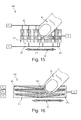
- Fig. 15 represents an implementation of the one-dimensional sensor of Fig. 14 with three weighted sensor elements 411, 412 and 413 wherein the weighted sensor capacitors 421 and 422 may be created from unit capacitors that are evenly distributed over each sensor element area according to the required weights.
- the purpose of this embodiment is to determine the position of a human finger 50 during a horizontal movement 52 in close proximity with the sensor.
- Fig. 16 indicates a one-dimensional sensor structure comprising three parallel sensor arrays, each comprising three triangular shaped sensor capacitors 421, 422 and 423 connected to the signal lines X1, X2 and X3.
- This sensor structure may provide an economic implementation of a one-dimensional position sensor. The position of a human finger 50 during a horizontal movement 52 is calculated as mentioned above.
- Fig. 17 represents an embodiment 400 of a two-dimensional position sensor, based on three interleaved sensor capacitors in x-direction and three interleaved sensor capacitors in y-direction.
- the six capacitors are formed by unit sensor capacitors 421.
- a complementary sampling unit according to Fig. 21 may be used to measure the six sensing capacitors.
- the position of a human finger 50 may be detected in a two dimensional plane 52.
- Fig. 18 represents an embodiment 400 of a two-dimensional position sensor, based on nine sensor elements with four weighted sensor capacitors each wherein the weights are applied by in total 16 unit capacitors each. Weights are applied as indicated, using the exemplary weighting factors 0.25, 0.50 and 0.75 repeatedly in x- and y- direction. Node Z is the summing node. According to the herein described method and system, the four sensing capacitors Cx1, Cx2, Cy1 and Cy2 are measured utilizing a complementary sampling unit according to Fig. 20 . As a result, 75% of all weighted sensor capacitors may be evaluated in one measurement.
- the position components x and y may be calculated as:
- Fig. 19 indicates an embodiment representing a keypad.
- the keypad 450 comprises a sensor array comprising 12 weighted sensor elements 411 meant to identify key presses by a human finger 50 at certain predefined locations.
- the keypad according to the herein described method and system may be configured as a meandered one-dimensional position sensor with unique weights assigned to each keypad location. Weighting may be assigned by using unit capacitors as indicated to assign unique weights.
- Fig. 20 illustrates an embodiment of a complementary sampling unit with four sensor capacitors.
- the GPIOs 301-304, 310 and 311 are configured to implement one-dimensional and two-dimensional position detectors.
- Fig. 21 illustrates the GPIO structure required to implement the two-dimensional position detector of Fig. 17 .
- Fig. 22 is an embodiment of a sampling unit utilizing a software programmable comparator 101 that may be used to speed up the measurement process.
- the reference voltage is provided by an internal digital to analog converter (DAC) 350. Normally, it takes some time to switch the GPIO 310 from output to input mode. Skipping the measurement step for a certain amount of cycles may speed up the integration.
- the programmable comparator may be used to detect the voltage level at which the measurement has to be enabled.
- Another purpose of the programmable comparator according to the herein described method and system is to implement an adaptable reference level that is set sufficiently below the maximum voltage across the integration capacitor Cint.
- the herein described method and system may enable the creation of a low power, low complexity touch based user interfaces for a variety of applications.
- a one-dimensional touch sensor interface may be embedded into a contactless smartcard.
- a one-dimensional position sensor according to Fig. 15 may be used to identify a horizontal sweep of a human finger on the surface of the smartcard. The smartcards communication interface stays deactivated until it gets deliberately activated with a horizontal finger movement over the sensing area by the card holder.
- a two-dimensional position sensor may be used to provide a touch interface on a smartcards surface.
- An electronic ID-Card may be equipped with a two-dimensional position sensor according to Figs. 17 or 18 .
- the sensor may be used to enter a Personal Identification Number (PIN) directly on the smartcard's surface by drawing the PIN with a finger or a stylus.
- PIN Personal Identification Number
- the two-dimensional position sensor provides a stream of position data to an online-handwriting recognition that retrieves the entered digits. This approach may make external keypads obsolete and furthermore may avoid skimming the PIN on the way from the keypad to a host application since the PIN never leaves the smart card unencrypted.
- the PIN can either be entered via touch buttons that represent different characters or by gesture recognition where different gestures represent different characters.
- This authentication method is especially beneficial if an external secure keypad for PIN entry cannot be provided.
- the use case is quite common in secure online authentication, e.g., in online payment.
- the keypad according to Fig. 19 can be applied, which is based on a one-dimensional slider implementation.
- This keypad may be implemented on generic MCUs with minimum number of GPIOs.
- the overhead for implementing the touch sensor reduces to a minor increase in the software footprint.
- Fig. 23 is an embodiment that represents several implementations of the capacitive sensor interface.
- the capacitive sensor interface may be integrated into a MCU 80 with a programmable state machine 81.
- the integration of the capacitive sensor interface utilizing a programmable state machine offloads the CPU from timing critical tasks and furthermore reduces the power consumption of the MCU which is crucial for smartcard which are powered by the electromagnetic field of a reader device.
- the capacitive sensor interface 81 may be integrated directly into a Secure Element 81 comprising a cryptographic processor.
- the integration of the capacitive proximity sensor interface into the Secure Element avoids insecure connections between a capacitive sensor device and a secure element.
- the output of the secure element is directly encrypted data.
Landscapes
- Engineering & Computer Science (AREA)
- General Engineering & Computer Science (AREA)
- Theoretical Computer Science (AREA)
- Physics & Mathematics (AREA)
- General Physics & Mathematics (AREA)
- Human Computer Interaction (AREA)
- Measurement Of Length, Angles, Or The Like Using Electric Or Magnetic Means (AREA)
- Electronic Switches (AREA)
Priority Applications (3)
| Application Number | Priority Date | Filing Date | Title |
|---|---|---|---|
| EP12169581.1A EP2667156B1 (fr) | 2012-05-25 | 2012-05-25 | Système capacitif de capteur de position |
| US13/898,384 US9317164B2 (en) | 2012-05-25 | 2013-05-20 | Capacitive position sensor system |
| CN201310191534.2A CN103425370B (zh) | 2012-05-25 | 2013-05-22 | 电容式位置传感器系统 |
Applications Claiming Priority (1)
| Application Number | Priority Date | Filing Date | Title |
|---|---|---|---|
| EP12169581.1A EP2667156B1 (fr) | 2012-05-25 | 2012-05-25 | Système capacitif de capteur de position |
Publications (2)
| Publication Number | Publication Date |
|---|---|
| EP2667156A1 true EP2667156A1 (fr) | 2013-11-27 |
| EP2667156B1 EP2667156B1 (fr) | 2015-10-21 |
Family
ID=46207866
Family Applications (1)
| Application Number | Title | Priority Date | Filing Date |
|---|---|---|---|
| EP12169581.1A Active EP2667156B1 (fr) | 2012-05-25 | 2012-05-25 | Système capacitif de capteur de position |
Country Status (3)
| Country | Link |
|---|---|
| US (1) | US9317164B2 (fr) |
| EP (1) | EP2667156B1 (fr) |
| CN (1) | CN103425370B (fr) |
Cited By (11)
| Publication number | Priority date | Publication date | Assignee | Title |
|---|---|---|---|---|
| EP2933711A1 (fr) | 2014-04-16 | 2015-10-21 | Nxp B.V. | Unité d'interface utilisateur, carte à puce et procédé de fabrication |
| US9317675B2 (en) | 2013-03-19 | 2016-04-19 | Nxp B.V. | Smartcard, smartcard system and method for configuring a smartcard |
| EP3035173A1 (fr) | 2014-12-15 | 2016-06-22 | Nxp B.V. | Unité d'interface utilisateur, dispositif électronique et procédé de fabrication |
| EP3057235A1 (fr) * | 2015-02-10 | 2016-08-17 | Nxp B.V. | Capteur tactile |
| US20160313830A1 (en) * | 2015-04-24 | 2016-10-27 | Nxp B.V. | Electronic device |
| CN106990861A (zh) * | 2016-01-20 | 2017-07-28 | 丽智科技股份有限公司 | 智能感测触控装置 |
| EP3111817A4 (fr) * | 2014-02-27 | 2017-08-02 | Mitsubishi Electric Corporation | Dispositif de sèche-mains |
| US9826865B2 (en) | 2014-02-27 | 2017-11-28 | Mitsubishi Electric Corporation | Hand dryer apparatus |
| WO2017208068A1 (fr) * | 2016-06-03 | 2017-12-07 | Brandenburg (Uk) Limited | Détection d'objets |
| US10372283B2 (en) | 2017-01-16 | 2019-08-06 | Nxp B.V. | Electronic device |
| US10579851B2 (en) | 2017-02-02 | 2020-03-03 | Nxp B. V. | Fingerprint processing system and method |
Families Citing this family (21)
| Publication number | Priority date | Publication date | Assignee | Title |
|---|---|---|---|---|
| US9612265B1 (en) | 2011-09-23 | 2017-04-04 | Cypress Semiconductor Corporation | Methods and apparatus to detect a conductive object |
| EP2717136B1 (fr) | 2012-10-02 | 2017-07-12 | Nxp B.V. | Système de capteur de position capacitive |
| WO2014057843A1 (fr) * | 2012-10-11 | 2014-04-17 | 株式会社クリエイティブ テクノロジー | Porte-pièce et procédé utilisant celui-ci pour détecter un décalage latéral d'une pièce |
| JP2016189037A (ja) * | 2013-08-26 | 2016-11-04 | パナソニックIpマネジメント株式会社 | センサ構造体およびその検出方法 |
| US8872526B1 (en) * | 2013-09-10 | 2014-10-28 | Cypress Semiconductor Corporation | Interleaving sense elements of a capacitive-sense array |
| CN106488729B (zh) * | 2014-06-27 | 2019-12-13 | 皇家飞利浦有限公司 | 具有功率控制的家用器具 |
| DE102015008485A1 (de) * | 2015-07-01 | 2017-01-05 | Leopold Kostal Gmbh & Co. Kg | Verfahren zum Messen eines Kapazitätswertes |
| US10444892B2 (en) * | 2015-10-07 | 2019-10-15 | Microchip Technology Incorporated | Capacitance measurement device with reduced noise |
| EP3156947B1 (fr) | 2015-10-12 | 2020-01-01 | Nxp B.V. | Dispositif électronique |
| US10365775B2 (en) * | 2016-01-21 | 2019-07-30 | Microchip Technology Incorporated | Method and system for sensing impedance change in the local space between electrodes |
| US11542692B2 (en) | 2016-06-08 | 2023-01-03 | Bradley Fixtures Corporation | Multi-function fixture with soap refill system |
| US11015329B2 (en) | 2016-06-08 | 2021-05-25 | Bradley Corporation | Lavatory drain system |
| US11083340B2 (en) | 2016-06-08 | 2021-08-10 | Bradley Fixtures Corporation | Multi-function fixture for a lavatory system |
| EP3505032B1 (fr) * | 2016-08-26 | 2022-07-06 | Mitsubishi Electric Corporation | Sèche-main |
| CN106580359B (zh) * | 2016-12-02 | 2020-04-14 | 中国科学院深圳先进技术研究院 | 探测器信号处理方法及装置 |
| US10444916B2 (en) * | 2017-03-10 | 2019-10-15 | Cypress Semiconductor Corporation | Combined inductive sensing and capacitive sensing |
| EP3385825B1 (fr) * | 2017-04-04 | 2021-06-30 | Nxp B.V. | Système de capteur et procédé de détection |
| TWI685782B (zh) * | 2017-10-11 | 2020-02-21 | 瑞鼎科技股份有限公司 | 電容式觸控感測電路及其電荷補償方法 |
| US10585539B2 (en) * | 2017-10-26 | 2020-03-10 | Novatek Microelectronics Corp. | High sensitivity readout circuit for touch panel |
| CN110380715B (zh) * | 2018-04-12 | 2021-11-23 | 深圳市赛元微电子有限公司 | 一种电容式触控按键的检测方法和检测装置 |
| EP3805974A1 (fr) | 2019-10-11 | 2021-04-14 | Nxp B.V. | Dispositif, système et procédé de détection de fraudes |
Citations (3)
| Publication number | Priority date | Publication date | Assignee | Title |
|---|---|---|---|---|
| US4894620A (en) | 1988-04-11 | 1990-01-16 | At&T Bell Laboratories | Switched-capacitor circuit with large time constant |
| US20030132764A1 (en) * | 2002-01-11 | 2003-07-17 | Fasen Donald J. | Capacitance-based position sensor with integrating demodulator |
| WO2004040240A1 (fr) * | 2002-10-31 | 2004-05-13 | Harald Philipp | Capteur de position capacitif a transfert de charge |
Family Cites Families (9)
| Publication number | Priority date | Publication date | Assignee | Title |
|---|---|---|---|---|
| US4441082A (en) * | 1981-10-09 | 1984-04-03 | American Microsystems, Inc. | Switched capacitor automatic gain control loop |
| US5730165A (en) | 1995-12-26 | 1998-03-24 | Philipp; Harald | Time domain capacitive field detector |
| US6466036B1 (en) | 1998-11-25 | 2002-10-15 | Harald Philipp | Charge transfer capacitance measurement circuit |
| US8095091B1 (en) * | 2007-05-18 | 2012-01-10 | Marvell International Ltd. | Transmit power amplification control for wireless device |
| US8786575B2 (en) * | 2009-05-18 | 2014-07-22 | Empire Technology Development LLP | Touch-sensitive device and method |
| US20110082390A1 (en) * | 2009-10-06 | 2011-04-07 | Krieter Marcus | Compliant pressure actuated surface sensor for on body detection |
| KR20110091380A (ko) * | 2010-02-05 | 2011-08-11 | 삼성전자주식회사 | 터치 패널의 노이즈 보상 방법 및 장치 |
| US8854107B2 (en) * | 2010-05-04 | 2014-10-07 | Zinitix Co., Ltd. | Integrator circuit with inverting integrator and non-inverting integrator |
| EP2575084A1 (fr) | 2011-09-30 | 2013-04-03 | Nxp B.V. | Jeton de sécurité et système d'authentification |
-
2012
- 2012-05-25 EP EP12169581.1A patent/EP2667156B1/fr active Active
-
2013
- 2013-05-20 US US13/898,384 patent/US9317164B2/en active Active
- 2013-05-22 CN CN201310191534.2A patent/CN103425370B/zh active Active
Patent Citations (3)
| Publication number | Priority date | Publication date | Assignee | Title |
|---|---|---|---|---|
| US4894620A (en) | 1988-04-11 | 1990-01-16 | At&T Bell Laboratories | Switched-capacitor circuit with large time constant |
| US20030132764A1 (en) * | 2002-01-11 | 2003-07-17 | Fasen Donald J. | Capacitance-based position sensor with integrating demodulator |
| WO2004040240A1 (fr) * | 2002-10-31 | 2004-05-13 | Harald Philipp | Capteur de position capacitif a transfert de charge |
Non-Patent Citations (1)
| Title |
|---|
| GREGORIAN ET AL.: "Switched-Capacitor Circuit Design", PROCEEDINGS OF THE IEEE, vol. 71, no. 8, August 1983 (1983-08-01), XP002603925 |
Cited By (25)
| Publication number | Priority date | Publication date | Assignee | Title |
|---|---|---|---|---|
| US9317675B2 (en) | 2013-03-19 | 2016-04-19 | Nxp B.V. | Smartcard, smartcard system and method for configuring a smartcard |
| EP3111817A4 (fr) * | 2014-02-27 | 2017-08-02 | Mitsubishi Electric Corporation | Dispositif de sèche-mains |
| US9826865B2 (en) | 2014-02-27 | 2017-11-28 | Mitsubishi Electric Corporation | Hand dryer apparatus |
| CN105045441A (zh) * | 2014-04-16 | 2015-11-11 | 恩智浦有限公司 | 用户接口单元、智能卡和制造方法 |
| US9406013B2 (en) | 2014-04-16 | 2016-08-02 | Nxp B.V. | User interface unit, smart card and manufacturing method |
| CN105045441B (zh) * | 2014-04-16 | 2018-07-20 | 恩智浦有限公司 | 用户接口单元、智能卡和制造方法 |
| EP2933711A1 (fr) | 2014-04-16 | 2015-10-21 | Nxp B.V. | Unité d'interface utilisateur, carte à puce et procédé de fabrication |
| EP3035173A1 (fr) | 2014-12-15 | 2016-06-22 | Nxp B.V. | Unité d'interface utilisateur, dispositif électronique et procédé de fabrication |
| US9916053B2 (en) | 2014-12-15 | 2018-03-13 | Nxp B.V. | User interface unit, electronic device and manufacturing method |
| CN105868821A (zh) * | 2015-02-10 | 2016-08-17 | 恩智浦有限公司 | 触摸传感器 |
| EP3057235A1 (fr) * | 2015-02-10 | 2016-08-17 | Nxp B.V. | Capteur tactile |
| CN105868821B (zh) * | 2015-02-10 | 2019-01-18 | 恩智浦有限公司 | 触摸传感器 |
| US10198110B2 (en) | 2015-02-10 | 2019-02-05 | Nxp B.V. | Touch sensor that utilizes a touch area with a single conductive path |
| US11100380B2 (en) * | 2015-04-24 | 2021-08-24 | Nxp B.V. | Electronic device |
| US20160313830A1 (en) * | 2015-04-24 | 2016-10-27 | Nxp B.V. | Electronic device |
| CN106990861A (zh) * | 2016-01-20 | 2017-07-28 | 丽智科技股份有限公司 | 智能感测触控装置 |
| KR20190016520A (ko) * | 2016-06-03 | 2019-02-18 | 브랜덴버그 (유케이) 리미티드 | 물체의 감지 |
| CN109690256A (zh) * | 2016-06-03 | 2019-04-26 | 勃兰登堡(英国)有限公司 | 物体的感测 |
| US10932459B2 (en) | 2016-06-03 | 2021-03-02 | Brandenburg (Uk) Limited | Sensing of objects |
| WO2017208068A1 (fr) * | 2016-06-03 | 2017-12-07 | Brandenburg (Uk) Limited | Détection d'objets |
| US11477975B2 (en) | 2016-06-03 | 2022-10-25 | Bradenburg UK Limited | Sensing of objects |
| KR102462191B1 (ko) * | 2016-06-03 | 2022-11-02 | 브랜덴버그 (유케이) 리미티드 | 물체의 감지 |
| US11959779B2 (en) | 2016-06-03 | 2024-04-16 | Brandenburg (Uk) Limited | Sensing of objects |
| US10372283B2 (en) | 2017-01-16 | 2019-08-06 | Nxp B.V. | Electronic device |
| US10579851B2 (en) | 2017-02-02 | 2020-03-03 | Nxp B. V. | Fingerprint processing system and method |
Also Published As
| Publication number | Publication date |
|---|---|
| CN103425370A (zh) | 2013-12-04 |
| US9317164B2 (en) | 2016-04-19 |
| CN103425370B (zh) | 2016-05-11 |
| US20140152610A1 (en) | 2014-06-05 |
| EP2667156B1 (fr) | 2015-10-21 |
Similar Documents
| Publication | Publication Date | Title |
|---|---|---|
| EP2667156B1 (fr) | Système capacitif de capteur de position | |
| US9977061B2 (en) | Capacitive position sensor system | |
| US11481066B2 (en) | Providing a baseline capacitance for a capacitance sensing channel | |
| US10133432B2 (en) | Technique for increasing the sensitivity of capacitive sense arrays | |
| JP5285423B2 (ja) | 近接度の検出のために電荷移動静電容量センサを保護するための方法およびシステム | |
| US9007342B2 (en) | Dynamic mode switching for fast touch response | |
| US8624870B2 (en) | System for and method of transferring charge to convert capacitance to voltage for touchscreen controllers | |
| US9013195B2 (en) | Mutual capacitance sensing circuits, methods and systems | |
| CN105531654B (zh) | 注入触摸噪声分析 | |
| US8258986B2 (en) | Capacitive-matrix keyboard with multiple touch detection | |
| KR20110121590A (ko) | 멀티-칩 터치 스크린 | |
| KR20190015436A (ko) | 다단 증분 스위칭 체계 | |
| US9507454B1 (en) | Enhanced linearity of gestures on a touch-sensitive surface | |
| US9285932B1 (en) | Negative touch recovery for mutual capacitance scanning systems | |
| CN114487784A (zh) | 电容检测电路、触控芯片及电子设备 |
Legal Events
| Date | Code | Title | Description |
|---|---|---|---|
| PUAI | Public reference made under article 153(3) epc to a published international application that has entered the european phase |
Free format text: ORIGINAL CODE: 0009012 |
|
| AK | Designated contracting states |
Kind code of ref document: A1 Designated state(s): AL AT BE BG CH CY CZ DE DK EE ES FI FR GB GR HR HU IE IS IT LI LT LU LV MC MK MT NL NO PL PT RO RS SE SI SK SM TR |
|
| AX | Request for extension of the european patent |
Extension state: BA ME |
|
| 17P | Request for examination filed |
Effective date: 20131031 |
|
| RBV | Designated contracting states (corrected) |
Designated state(s): AL AT BE BG CH CY CZ DE DK EE ES FI FR GB GR HR HU IE IS IT LI LT LU LV MC MK MT NL NO PL PT RO RS SE SI SK SM TR |
|
| GRAP | Despatch of communication of intention to grant a patent |
Free format text: ORIGINAL CODE: EPIDOSNIGR1 |
|
| INTG | Intention to grant announced |
Effective date: 20150430 |
|
| GRAP | Despatch of communication of intention to grant a patent |
Free format text: ORIGINAL CODE: EPIDOSNIGR1 |
|
| GRAS | Grant fee paid |
Free format text: ORIGINAL CODE: EPIDOSNIGR3 |
|
| GRAA | (expected) grant |
Free format text: ORIGINAL CODE: 0009210 |
|
| INTG | Intention to grant announced |
Effective date: 20150904 |
|
| AK | Designated contracting states |
Kind code of ref document: B1 Designated state(s): AL AT BE BG CH CY CZ DE DK EE ES FI FR GB GR HR HU IE IS IT LI LT LU LV MC MK MT NL NO PL PT RO RS SE SI SK SM TR |
|
| REG | Reference to a national code |
Ref country code: GB Ref legal event code: FG4D Ref country code: NL Ref legal event code: MP Effective date: 20151021 |
|
| REG | Reference to a national code |
Ref country code: CH Ref legal event code: EP |
|
| REG | Reference to a national code |
Ref country code: AT Ref legal event code: REF Ref document number: 756886 Country of ref document: AT Kind code of ref document: T Effective date: 20151115 |
|
| REG | Reference to a national code |
Ref country code: IE Ref legal event code: FG4D |
|
| REG | Reference to a national code |
Ref country code: DE Ref legal event code: R096 Ref document number: 602012011724 Country of ref document: DE |
|
| REG | Reference to a national code |
Ref country code: LT Ref legal event code: MG4D |
|
| REG | Reference to a national code |
Ref country code: AT Ref legal event code: MK05 Ref document number: 756886 Country of ref document: AT Kind code of ref document: T Effective date: 20151021 |
|
| REG | Reference to a national code |
Ref country code: FR Ref legal event code: PLFP Year of fee payment: 5 |
|
| PG25 | Lapsed in a contracting state [announced via postgrant information from national office to epo] |
Ref country code: NO Free format text: LAPSE BECAUSE OF FAILURE TO SUBMIT A TRANSLATION OF THE DESCRIPTION OR TO PAY THE FEE WITHIN THE PRESCRIBED TIME-LIMIT Effective date: 20160121 Ref country code: IT Free format text: LAPSE BECAUSE OF FAILURE TO SUBMIT A TRANSLATION OF THE DESCRIPTION OR TO PAY THE FEE WITHIN THE PRESCRIBED TIME-LIMIT Effective date: 20151021 Ref country code: ES Free format text: LAPSE BECAUSE OF FAILURE TO SUBMIT A TRANSLATION OF THE DESCRIPTION OR TO PAY THE FEE WITHIN THE PRESCRIBED TIME-LIMIT Effective date: 20151021 Ref country code: HR Free format text: LAPSE BECAUSE OF FAILURE TO SUBMIT A TRANSLATION OF THE DESCRIPTION OR TO PAY THE FEE WITHIN THE PRESCRIBED TIME-LIMIT Effective date: 20151021 Ref country code: IS Free format text: LAPSE BECAUSE OF FAILURE TO SUBMIT A TRANSLATION OF THE DESCRIPTION OR TO PAY THE FEE WITHIN THE PRESCRIBED TIME-LIMIT Effective date: 20160221 Ref country code: LT Free format text: LAPSE BECAUSE OF FAILURE TO SUBMIT A TRANSLATION OF THE DESCRIPTION OR TO PAY THE FEE WITHIN THE PRESCRIBED TIME-LIMIT Effective date: 20151021 Ref country code: NL Free format text: LAPSE BECAUSE OF FAILURE TO SUBMIT A TRANSLATION OF THE DESCRIPTION OR TO PAY THE FEE WITHIN THE PRESCRIBED TIME-LIMIT Effective date: 20151021 |
|
| PG25 | Lapsed in a contracting state [announced via postgrant information from national office to epo] |
Ref country code: AT Free format text: LAPSE BECAUSE OF FAILURE TO SUBMIT A TRANSLATION OF THE DESCRIPTION OR TO PAY THE FEE WITHIN THE PRESCRIBED TIME-LIMIT Effective date: 20151021 Ref country code: PT Free format text: LAPSE BECAUSE OF FAILURE TO SUBMIT A TRANSLATION OF THE DESCRIPTION OR TO PAY THE FEE WITHIN THE PRESCRIBED TIME-LIMIT Effective date: 20160222 Ref country code: PL Free format text: LAPSE BECAUSE OF FAILURE TO SUBMIT A TRANSLATION OF THE DESCRIPTION OR TO PAY THE FEE WITHIN THE PRESCRIBED TIME-LIMIT Effective date: 20151021 Ref country code: RS Free format text: LAPSE BECAUSE OF FAILURE TO SUBMIT A TRANSLATION OF THE DESCRIPTION OR TO PAY THE FEE WITHIN THE PRESCRIBED TIME-LIMIT Effective date: 20151021 Ref country code: GR Free format text: LAPSE BECAUSE OF FAILURE TO SUBMIT A TRANSLATION OF THE DESCRIPTION OR TO PAY THE FEE WITHIN THE PRESCRIBED TIME-LIMIT Effective date: 20160122 Ref country code: FI Free format text: LAPSE BECAUSE OF FAILURE TO SUBMIT A TRANSLATION OF THE DESCRIPTION OR TO PAY THE FEE WITHIN THE PRESCRIBED TIME-LIMIT Effective date: 20151021 Ref country code: SE Free format text: LAPSE BECAUSE OF FAILURE TO SUBMIT A TRANSLATION OF THE DESCRIPTION OR TO PAY THE FEE WITHIN THE PRESCRIBED TIME-LIMIT Effective date: 20151021 Ref country code: LV Free format text: LAPSE BECAUSE OF FAILURE TO SUBMIT A TRANSLATION OF THE DESCRIPTION OR TO PAY THE FEE WITHIN THE PRESCRIBED TIME-LIMIT Effective date: 20151021 |
|
| REG | Reference to a national code |
Ref country code: DE Ref legal event code: R097 Ref document number: 602012011724 Country of ref document: DE |
|
| PG25 | Lapsed in a contracting state [announced via postgrant information from national office to epo] |
Ref country code: CZ Free format text: LAPSE BECAUSE OF FAILURE TO SUBMIT A TRANSLATION OF THE DESCRIPTION OR TO PAY THE FEE WITHIN THE PRESCRIBED TIME-LIMIT Effective date: 20151021 |
|
| PLBE | No opposition filed within time limit |
Free format text: ORIGINAL CODE: 0009261 |
|
| STAA | Information on the status of an ep patent application or granted ep patent |
Free format text: STATUS: NO OPPOSITION FILED WITHIN TIME LIMIT |
|
| PG25 | Lapsed in a contracting state [announced via postgrant information from national office to epo] |
Ref country code: BE Free format text: LAPSE BECAUSE OF NON-PAYMENT OF DUE FEES Effective date: 20160531 Ref country code: EE Free format text: LAPSE BECAUSE OF FAILURE TO SUBMIT A TRANSLATION OF THE DESCRIPTION OR TO PAY THE FEE WITHIN THE PRESCRIBED TIME-LIMIT Effective date: 20151021 Ref country code: SK Free format text: LAPSE BECAUSE OF FAILURE TO SUBMIT A TRANSLATION OF THE DESCRIPTION OR TO PAY THE FEE WITHIN THE PRESCRIBED TIME-LIMIT Effective date: 20151021 Ref country code: DK Free format text: LAPSE BECAUSE OF FAILURE TO SUBMIT A TRANSLATION OF THE DESCRIPTION OR TO PAY THE FEE WITHIN THE PRESCRIBED TIME-LIMIT Effective date: 20151021 Ref country code: RO Free format text: LAPSE BECAUSE OF FAILURE TO SUBMIT A TRANSLATION OF THE DESCRIPTION OR TO PAY THE FEE WITHIN THE PRESCRIBED TIME-LIMIT Effective date: 20151021 Ref country code: SM Free format text: LAPSE BECAUSE OF FAILURE TO SUBMIT A TRANSLATION OF THE DESCRIPTION OR TO PAY THE FEE WITHIN THE PRESCRIBED TIME-LIMIT Effective date: 20151021 |
|
| 26N | No opposition filed |
Effective date: 20160722 |
|
| PG25 | Lapsed in a contracting state [announced via postgrant information from national office to epo] |
Ref country code: SI Free format text: LAPSE BECAUSE OF FAILURE TO SUBMIT A TRANSLATION OF THE DESCRIPTION OR TO PAY THE FEE WITHIN THE PRESCRIBED TIME-LIMIT Effective date: 20151021 |
|
| PG25 | Lapsed in a contracting state [announced via postgrant information from national office to epo] |
Ref country code: LU Free format text: LAPSE BECAUSE OF FAILURE TO SUBMIT A TRANSLATION OF THE DESCRIPTION OR TO PAY THE FEE WITHIN THE PRESCRIBED TIME-LIMIT Effective date: 20160525 Ref country code: BE Free format text: LAPSE BECAUSE OF FAILURE TO SUBMIT A TRANSLATION OF THE DESCRIPTION OR TO PAY THE FEE WITHIN THE PRESCRIBED TIME-LIMIT Effective date: 20151021 |
|
| REG | Reference to a national code |
Ref country code: CH Ref legal event code: PL |
|
| PG25 | Lapsed in a contracting state [announced via postgrant information from national office to epo] |
Ref country code: CH Free format text: LAPSE BECAUSE OF NON-PAYMENT OF DUE FEES Effective date: 20160531 Ref country code: LI Free format text: LAPSE BECAUSE OF NON-PAYMENT OF DUE FEES Effective date: 20160531 |
|
| REG | Reference to a national code |
Ref country code: IE Ref legal event code: MM4A |
|
| REG | Reference to a national code |
Ref country code: FR Ref legal event code: PLFP Year of fee payment: 6 |
|
| PG25 | Lapsed in a contracting state [announced via postgrant information from national office to epo] |
Ref country code: IE Free format text: LAPSE BECAUSE OF NON-PAYMENT OF DUE FEES Effective date: 20160525 |
|
| REG | Reference to a national code |
Ref country code: FR Ref legal event code: PLFP Year of fee payment: 7 |
|
| PG25 | Lapsed in a contracting state [announced via postgrant information from national office to epo] |
Ref country code: CY Free format text: LAPSE BECAUSE OF FAILURE TO SUBMIT A TRANSLATION OF THE DESCRIPTION OR TO PAY THE FEE WITHIN THE PRESCRIBED TIME-LIMIT Effective date: 20151021 Ref country code: HU Free format text: LAPSE BECAUSE OF FAILURE TO SUBMIT A TRANSLATION OF THE DESCRIPTION OR TO PAY THE FEE WITHIN THE PRESCRIBED TIME-LIMIT; INVALID AB INITIO Effective date: 20120525 |
|
| PG25 | Lapsed in a contracting state [announced via postgrant information from national office to epo] |
Ref country code: MK Free format text: LAPSE BECAUSE OF FAILURE TO SUBMIT A TRANSLATION OF THE DESCRIPTION OR TO PAY THE FEE WITHIN THE PRESCRIBED TIME-LIMIT Effective date: 20151021 Ref country code: MC Free format text: LAPSE BECAUSE OF FAILURE TO SUBMIT A TRANSLATION OF THE DESCRIPTION OR TO PAY THE FEE WITHIN THE PRESCRIBED TIME-LIMIT Effective date: 20151021 Ref country code: TR Free format text: LAPSE BECAUSE OF FAILURE TO SUBMIT A TRANSLATION OF THE DESCRIPTION OR TO PAY THE FEE WITHIN THE PRESCRIBED TIME-LIMIT Effective date: 20151021 Ref country code: MT Free format text: LAPSE BECAUSE OF NON-PAYMENT OF DUE FEES Effective date: 20160531 |
|
| PG25 | Lapsed in a contracting state [announced via postgrant information from national office to epo] |
Ref country code: BG Free format text: LAPSE BECAUSE OF FAILURE TO SUBMIT A TRANSLATION OF THE DESCRIPTION OR TO PAY THE FEE WITHIN THE PRESCRIBED TIME-LIMIT Effective date: 20151021 |
|
| PG25 | Lapsed in a contracting state [announced via postgrant information from national office to epo] |
Ref country code: AL Free format text: LAPSE BECAUSE OF FAILURE TO SUBMIT A TRANSLATION OF THE DESCRIPTION OR TO PAY THE FEE WITHIN THE PRESCRIBED TIME-LIMIT Effective date: 20151021 |
|
| PGFP | Annual fee paid to national office [announced via postgrant information from national office to epo] |
Ref country code: FR Payment date: 20230420 Year of fee payment: 12 Ref country code: DE Payment date: 20230419 Year of fee payment: 12 |
|
| P01 | Opt-out of the competence of the unified patent court (upc) registered |
Effective date: 20230725 |
|
| PGFP | Annual fee paid to national office [announced via postgrant information from national office to epo] |
Ref country code: GB Payment date: 20230420 Year of fee payment: 12 |