EP2667084A1 - Tragbare elektrische Lampe mit Strombegrenzungsvorrichtung - Google Patents
Tragbare elektrische Lampe mit Strombegrenzungsvorrichtung Download PDFInfo
- Publication number
- EP2667084A1 EP2667084A1 EP20130354019 EP13354019A EP2667084A1 EP 2667084 A1 EP2667084 A1 EP 2667084A1 EP 20130354019 EP20130354019 EP 20130354019 EP 13354019 A EP13354019 A EP 13354019A EP 2667084 A1 EP2667084 A1 EP 2667084A1
- Authority
- EP
- European Patent Office
- Prior art keywords
- voltage
- transistor
- limiting
- additional
- coupled
- Prior art date
- Legal status (The legal status is an assumption and is not a legal conclusion. Google has not performed a legal analysis and makes no representation as to the accuracy of the status listed.)
- Withdrawn
Links
- 230000001681 protective effect Effects 0.000 claims description 15
- 229910044991 metal oxide Inorganic materials 0.000 abstract 1
- 150000004706 metal oxides Chemical class 0.000 abstract 1
- 238000010438 heat treatment Methods 0.000 description 14
- 239000003990 capacitor Substances 0.000 description 8
- 239000002360 explosive Substances 0.000 description 4
- 230000015556 catabolic process Effects 0.000 description 1
- 230000006378 damage Effects 0.000 description 1
- 230000007547 defect Effects 0.000 description 1
- 238000007654 immersion Methods 0.000 description 1
- 239000011810 insulating material Substances 0.000 description 1
- 239000007769 metal material Substances 0.000 description 1
- 229920006395 saturated elastomer Polymers 0.000 description 1
- 238000011144 upstream manufacturing Methods 0.000 description 1
Images

Classifications
-
- H—ELECTRICITY
- H05—ELECTRIC TECHNIQUES NOT OTHERWISE PROVIDED FOR
- H05B—ELECTRIC HEATING; ELECTRIC LIGHT SOURCES NOT OTHERWISE PROVIDED FOR; CIRCUIT ARRANGEMENTS FOR ELECTRIC LIGHT SOURCES, IN GENERAL
- H05B47/00—Circuit arrangements for operating light sources in general, i.e. where the type of light source is not relevant
- H05B47/20—Responsive to malfunctions or to light source life; for protection
- H05B47/28—Circuit arrangements for protecting against abnormal temperature
-
- F—MECHANICAL ENGINEERING; LIGHTING; HEATING; WEAPONS; BLASTING
- F21—LIGHTING
- F21L—LIGHTING DEVICES OR SYSTEMS THEREOF, BEING PORTABLE OR SPECIALLY ADAPTED FOR TRANSPORTATION
- F21L4/00—Electric lighting devices with self-contained electric batteries or cells
-
- F—MECHANICAL ENGINEERING; LIGHTING; HEATING; WEAPONS; BLASTING
- F21—LIGHTING
- F21V—FUNCTIONAL FEATURES OR DETAILS OF LIGHTING DEVICES OR SYSTEMS THEREOF; STRUCTURAL COMBINATIONS OF LIGHTING DEVICES WITH OTHER ARTICLES, NOT OTHERWISE PROVIDED FOR
- F21V25/00—Safety devices structurally associated with lighting devices
- F21V25/10—Safety devices structurally associated with lighting devices coming into action when lighting device is overloaded, e.g. thermal switch
-
- H—ELECTRICITY
- H02—GENERATION; CONVERSION OR DISTRIBUTION OF ELECTRIC POWER
- H02H—EMERGENCY PROTECTIVE CIRCUIT ARRANGEMENTS
- H02H9/00—Emergency protective circuit arrangements for limiting excess current or voltage without disconnection
- H02H9/008—Intrinsically safe circuits
Definitions
- the invention relates to a portable electric lamp with current limiting device, and in particular to a portable electric lamp used in explosive environment, including a frontal electric lamp compact housing.
- small space-saving portable electric lamps comprising a lighting module housed in a housing having a compact body.
- the lamp comprises a support provided with a strap for carrying the lamp on the head.
- Such lamps can be used in an explosive environment and must comply with stringent safety standards.
- ATEX Exlosive Atmospheres
- the current standards impose a limitation of the supply current of the lamp modules of lamps, to a value such that a defect of the lamp can not cause a heating or a spark that can cause ignition.
- Some lamps are equipped with a current limiting device comprising a resistor connected in series with a fuse.
- this limitation device has the disadvantage of consuming energy for lamps having a powerful lighting.
- this device imposes a nominal operation about 1.7 times lower than the thermal limit imposed by the standard, because according to the general specifications, the breakdown current of a fuse is about 1.7 times higher than the rated current.
- this limitation device requires the replacement of the fuse at each mishandling of the user, for example during a short circuit with a tool, immersion of the lamp, etc. This necessarily requires disassembly of the lamp, or scrapping.
- the maximum allowed current is approximately equal to 35% of the maximum heating current, to ensure the non-destruction of the fuse and to comply with heating conditions of the lamps fixed by the standards.
- the constraints imposed on the maximum current do not allow to use lamps with high lighting power.
- the object of the invention is to overcome these disadvantages, and in particular to produce a sufficiently compact portable electric lamp having means for limiting the current delivered by the power source.
- Another object of the invention is to provide a portable electric lamp that maintains a high level of performance in lighting power, autonomy and performance.
- a portable electric lamp comprising a lighting module, and a compact housing enclosing a power source for powering the lighting module and a device for limiting a current delivered by the power source.
- the limiting device comprises a control device and a limiting transistor whose drain is coupled to an output terminal of the lighting module and the gate is coupled to an output terminal of the control device, the limiting device comprising a resistive element coupled between a reference terminal of the power source and the source of the limiting transistor, the control device being configured to determine a supply voltage across the resistive element and to control the resistor transistor. so that it is in a closed state when the supply voltage is less than or equal to a voltage setpoint.
- the limiting device further comprises a thermal protection device configured to maintain the limiting transistor in an open state when the voltage between the drain and the source of the limiting transistor is greater than a reference voltage.
- the limitation device ensures a minimum of energy losses, and is particularly suitable for powerful lighting.
- such a limitation device makes it possible to control the limitation in current to the nearest of the nominal value of the use of the lamp. It is thus possible to achieve a thermal limit in nominal operation without exceeding that imposed by the standard in the event of lamp failure.
- a limiting device which limits the current delivered to the lighting module, while limiting the heating of the lamp. Furthermore, it is possible to use a maximum delivered current corresponding to about 95% of the maximum heating current set by the standards.
- the limiting transistor may be an NMOS type transistor.
- the thermal protection device may comprise a controlled protective switch coupled between the output of the control device and the reference terminal, the thermal protection device being configured to hold the protection switch in a closed state when the voltage between the drain and the source of the limiting transistor is greater than the reference voltage.
- the protection switch is a bipolar type protection transistor whose base is coupled to the output terminal of the lighting module, the reference voltage being equal to the threshold voltage of the protection transistor.
- the thermal protection device comprises a temperature sensor, and controls the protection switch in the closed state when the temperature of the limiting transistor is greater than a reference temperature.
- the controller may further include a voltage comparator having an output coupled to the output terminal of the controller, and two inputs respectively coupled to both terminals of the resistive element for determining the supply voltage.
- the lamp may also include an additional limiting device for limiting the supply current delivered by the power source, the additional limiting device comprising an additional control device and an additional controlled switch coupled between said limiting transistor and the terminal output of the lighting module, the additional controlled switch comprising a controller coupled to an output terminal of the additional controller, the additional controller being configured to determine the supply voltage and to control the switch further so that it is in a closed state when the supply voltage is less than or equal to the voltage setpoint.
- the additional controlled switch may be an additional limiting transistor and the additional limiting device further comprises an additional thermal protection device comprising an additional protection transistor of the bipolar type, the additional thermal protection device being configured to hold the transistors of limitation in the open state when the base-emitter voltage of the protection transistors is greater than their threshold voltage.
- the additional protective transistor can be coupled between the reference terminal, and the output terminal of the control device, and the output terminal of the additional control device, the base of the additional protection transistor. being coupled to the output terminal of the lighting module.
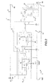
- FIG. 1 schematically shows a portable electric lamp 1 comprising a lighting module 2 and a compact housing 3 enclosing a power source 4, such as a battery or a battery, for supplying a supply current In to the module d 2, and a current limiting device 5 for limiting the supply current In.
- the lighting module 2 preferably comprises a light-emitting diode (LED) and lighting controls.
- the lighting module 2 may also include several LEDs, in particular LEDs with high lighting power.
- the portable electric lamp 1 may be a headlamp, or a flashlight, and the compact housing 3 may be made of insulating or metallic material.
- the lighting module 2 is separated from the compact housing 3, and the power source 4 is coupled to the lighting module 2 via electrical son 6, 7 each included in an insulating sheath.
- the lighting module 2 is included in the compact housing 3.
- the power source 4 comprises a short reference terminal and an output terminal B1 for delivering the current In.
- Lighting module 2 comprises, meanwhile, an input terminal B2 and an output terminal B3 respectively coupled to the electrical son 6, 7 to power the LED.
- the limitation device 5 comprises a control device 8, a controlled electronic switch Q1, referred to as a limiting switch, and a resistive element RSH, preferably a resistor.
- the limiting switch Q1 is coupled between the reference terminal Bref, via the resistive element RSH, and the output terminal B3 of the lighting module 2.
- the limitation switch Q1 comprises a control member coupled to an output terminal VG1 of the control device 8.
- the control device 8 further comprises two inputs e1, e2, respectively coupled across the resistive element RSH so as to be able to determine a voltage d VRSH power supply between an output terminal of the switch Q1 and the short reference terminal.
- the limitation switch Q1 may be a MEMS type switch (Micro Electro Mechanical System in English) or a transistor, preferably an NMOS type transistor.
- the control device 8 is configured to control the state of the limiting switch Q1, opening and closing.
- the control device 8 controls the limiting switch Q1 so that it is in a closed state when the supply voltage VRSH is less than or equal to a voltage setpoint Vpont, and in an otherwise open state .
- the supply voltage VRSH is lower than Vpont and the switch Q1 is in the closed state to supply the LED.
- the control device 8 commands the switch Q1 to open and the value of the supply current In drops.
- the supply voltage VRSH also drops to less than Vpont, and the control device 8 again controls the closing of the switch Q1 to power the LED.
- the voltage setpoint Vpont is adjusted to be equal to the voltage across the resistive element RSH when it is traversed by a desired maximum current Imax.
- the maximum current Imax is determined so that the lamp 1 does not show any heating that can cause ignition, even if the control device 8 and / or the limitation device 5 is in default.
- the limiting switch Q1 is an NMOS type transistor whose gate is coupled to the output VG1, via a resistor R13, the source is coupled to a terminal of the resistor RSH and the drain is coupled. at the output terminal B3 of the lighting module 2, either directly or via an additional electronic switch Q2 whose role will be described later.
- the control device 8 comprises an operational amplifier U3 mounted as a voltage comparator. The amplifier U3 comprises first and second inputs +, - respectively coupled to the inputs e1, e2 of the control device 8, and an output coupled to the output VG1, via a resistor R4.
- the output of the amplifier U3 is coupled to the second input e2 via a decoupling capacitor C1
- the first input e1 of the control device 8 is coupled to the reference terminal Bref, via a resistor R8 and a decoupling capacitor C12 connected in parallel
- the second input e2 is coupled to the source of Q1 via a resistor R6.
- the control device 8 further comprises a resistor R9 coupled between the first input e1 and the positive supply pin of the amplifier U3.
- the control device 8 also comprises a voltage regulator U1 and other capacitors C4 to C6 decoupling so as to provide a voltage setpoint Vpont stable.
- the regulator U1 makes it possible to supply a stable voltage for supplying the operational amplifier U3.
- the limiting device 5 may comprise a resistor R10 coupled between the voltage regulator U1 and the output terminal B1 of the power supply.
- the resistor R10 makes it possible to limit the power available for the control device 8.
- the resistor RSH makes it possible to create a VRSH voltage drop image of the current flowing through it, that is to say of the supply current In delivered to the LED.
- the operational amplifier U3 controls the supply current In by comparing the supply voltage VRSH with the voltage setpoint Vpont.
- the amplifier U3 provides a control voltage Vout on the gate of the transistor Q1 to control the latter.
- the LED When the LED is powered, it consumes an In current less than Imax and the VRSH supply voltage is lower than Vpont. In this case, the difference between the voltage setpoint and the supply voltage Vpont-VRSH is positive, and the output voltage Vout of the amplifier U3 is saturated in the high state and is equal to Vref.
- the limiting transistor Q1 is then controlled with a gate voltage VGS equal to Vref, it is in an on state, and the supply current In flows in the LED.
- the supply current In increases and becomes greater than Imax.
- the supply voltage VRSH becomes greater than Vpont
- the inputs +, - of the amplifier U3 are reversed and the output voltage Vout drops.
- the limiting transistor Q1 no longer flows because the gate voltage VGS no longer makes it possible to control the limiting transistor Q1 and the supply current In fall. It is therefore in linear operation in which the amplifier U3 controls the transistor Q1 at a stable operating point for passing the supply current In whose value is equal to Imax.
- the limiting device 5 may further comprise a thermal protection device 9 to prevent inadvertent heating of the limiting transistor Q1.
- the thermal protection device 9 prevents the power dissipated within the limiting transistor Q1 from exceeding a certain threshold corresponding to inadvertent heating.
- the thermal protection device 9 is configured to maintain the limiting switch Q1 in the open state when the temperature rise of the limiting switch Q1 is greater than a reference threshold. Thus, it limits the supply current of the LED while preventing the limiting switch Q1 to heat. Indeed, in case of short circuit, the switch Q1 is in the closed state and allows a maximum current Imax for a certain time, which creates a heating of the switch Q1.
- the thermal protection device 9 makes it possible, in particular, to reduce the size of the limiting transistor Q1 used and thus make the lamp 1 more compact.
- the supply current In is less than Imax
- VRSH is lower than Vpont
- the voltage VQ1 is zero.
- the base-emitter voltage Vbe of the protection transistor Q4 is therefore equal to VRSH. Consequently, the base-emitter voltage Vbe of the protection transistor Q4 is lower than its threshold voltage and the transistor Q4 does not conduct.
- a current Imax flows through the limiting transistor Q1 and the voltage VQ1 increases until it reaches a value equal to the difference Vref-VRSH between the voltage across the series-connected resistors R8 and R9 and the voltage at the terminals of the resistor RSH, with Vref having a value greater than the threshold voltage of the protective transistor Q4.
- Vref having a value greater than the threshold voltage of the protective transistor Q4.
- the base-emitter voltage Vbe of the protection transistor Q4 also increases and becomes greater than its threshold voltage, and the protective transistor Q4 conducts.
- the diode D2 brings the output voltage Vout of the amplifier U3 to the value of the voltage of the reference terminal Brief.
- the gate voltage of the limiting transistor Q1 is equal to that of the short reference terminal and the limiting transistor Q1 is then in the off state where it does not conduct.
- the limiting device 5 is electrically isolated, the voltage VRSH drops and the supply current In becomes zero, which prevents the heating of the limiting transistor Q1.
- a value is preferably chosen for the voltage setpoint Vpont which is lower than the threshold voltage of the protection transistor Q4.
- the thermal protection device 9 may comprise a voltage comparator configured to control the protective transistor Q4 in the closed state when the voltage across the limiting transistor Q1 is greater than a reference voltage for which it is considered that transistor Q1 heats up.
- the reference voltage is equal to the threshold voltage of the protective transistor Q4.
- the thermal protection device 9 comprises a temperature sensor, and is further configured to control the protection switch Q4 in the closed state when the temperature of the limiting switch Q1 is greater than a temperature for which it is considered that the limiting transistor Q1 has reached a heating limit.
- the portable electric lamp 1 may comprise an additional limitation device 10 to ensure redundancy of the limitation of the supply current In.
- the limitation device additional 10 comprises an additional control device 11 for controlling the additional electronic switch Q2, referred to additional limitation switch.
- the additional limitation switch Q2 may be a MEMS type switch.
- the additional limitation switch Q2 is an NMOS type transistor whose source is coupled with the drain of the limiting transistor Q1, the drain is coupled to the output terminal B3 of the lighting module 2 and the gate is coupled to an output terminal VG2 of the additional controller 11 via a resistor R14.
- the additional control device 11 has two inputs e3, e4 respectively coupled across the resistive element RSH so as to determine the supply voltage VRSH.
- the additional control device 11 comprises an operational amplifier U4 mounted as a voltage comparator.
- the amplifier U4 comprises first and second inputs +, - respectively coupled to the inputs e3, e4 of the additional control device 11, and an output coupled to the output terminal VG2, via a resistor R5.
- the output of the amplifier U4 is coupled to the second input e4 via a decoupling capacitor C2
- the first input e3 of the additional control device 11 is coupled to the reference terminal Brief, via a resistor R11 and a decoupling capacitor C13 connected in parallel
- the second input e4 is further coupled to the source of the limiting transistor Q1 via a resistor R7.
- the additional control device 11 further comprises a resistor R12 coupled between the first input e3 and the positive supply pin of the amplifier U4.
- the additional control device 11 also comprises a voltage regulator U2 and other decoupling capacitors C7 to C9 so as to provide a second stable voltage setpoint Vpont2 to the amplifier U4.
- the second voltage setpoint Vpont2 is equal to the first Vpont.
- the additional control device 11 is configured to control the additional limiting switch Q2 so that it is in a closed state when the supply voltage VRSH is less than or equal to the second voltage setpoint Vpont2, and in a state open otherwise.
- the protective transistor Q4 has its emitter coupled to the output VG2 of the additional control device 11 via an additional diode D4.
- the thermal protection device 9 simultaneously prevents the heating of the two limiting transistors Q1, Q2.
- the additional limiting device 10 may further comprise an additional thermal protection device 12 configured to maintain the limiting switches Q1, Q2 in the open state when the heating of at least one limiting switch Q1, Q2 is above a reference threshold.
- the additional thermal protection device 12 comprises an additional controlled electronic protection switch Q5, preferably a bipolar transistor NPN, coupled between the reference terminal Bref, and on the one hand the output VG1 of the control device 8 , via a diode D1, and secondly the VG2 output of the additional control device 11, through another diode D3.
- the base of the additional protection transistor Q5 is coupled to the output terminal B3 of the lighting module 2 via a resistor R2.
- the additional thermal protection device 12 comprises a decoupling capacitor C11 connected in parallel with the resistor R2.
- the supply voltage VRSH is lower than the voltage setpoints Vpont and Vpont2, and the limiting transistors Q1 and Q2 are in a conducting state to supply the LED.
- the supply voltage VRSH is higher than the voltage setpoints Vpont, Vpont2 and the control devices 8, 11 control respectively the limiting transistors Q1, Q2 in the off state.
- the supply voltage VRSH drops to be lower than the voltage setpoints Vpont, Vpont2 and the control devices 8, 11 again control the closing of the limiting transistors Q1, Q2 to power the LED.
- the supply current In is limited to the maximum value Imax.
- the limiting transistors Q1, Q2 when the voltage across the limiting transistors Q1, Q2 increases and the transistors Q1, Q2 heat up, the base-emitter voltage Vbe of the protection transistors Q4, Q5 then exceeds their threshold voltage and the transistors of protection Q4, Q5 become passing. Thus, the limiting transistors Q1, Q2 are maintained in the off state in which they no longer heat up.
- Such a lamp with both a current limiting device and a thermal protection device is particularly suitable for use in explosive environment.
Landscapes
- Engineering & Computer Science (AREA)
- General Engineering & Computer Science (AREA)
- Circuit Arrangement For Electric Light Sources In General (AREA)
Applications Claiming Priority (1)
| Application Number | Priority Date | Filing Date | Title |
|---|---|---|---|
| FR1201511A FR2991027A1 (fr) | 2012-05-25 | 2012-05-25 | Lampe electrique portative a dispositif de limitation en courant |
Publications (1)
| Publication Number | Publication Date |
|---|---|
| EP2667084A1 true EP2667084A1 (de) | 2013-11-27 |
Family
ID=48613549
Family Applications (1)
| Application Number | Title | Priority Date | Filing Date |
|---|---|---|---|
| EP20130354019 Withdrawn EP2667084A1 (de) | 2012-05-25 | 2013-05-27 | Tragbare elektrische Lampe mit Strombegrenzungsvorrichtung |
Country Status (3)
| Country | Link |
|---|---|
| US (1) | US9271378B2 (de) |
| EP (1) | EP2667084A1 (de) |
| FR (1) | FR2991027A1 (de) |
Cited By (1)
| Publication number | Priority date | Publication date | Assignee | Title |
|---|---|---|---|---|
| WO2017178470A3 (de) * | 2016-04-13 | 2017-12-14 | R. Stahl Schaltgeräte GmbH | Modul zur bereitstellung einer eigensicheren elektrischen ausgangsleistung sowie explosionsgeschützte leuchte |
Families Citing this family (1)
| Publication number | Priority date | Publication date | Assignee | Title |
|---|---|---|---|---|
| US10797482B2 (en) * | 2017-07-31 | 2020-10-06 | National Oilwell Varco, L.P. | Active limiting circuit for intrinsically safe equipment |
Citations (4)
| Publication number | Priority date | Publication date | Assignee | Title |
|---|---|---|---|---|
| US5107180A (en) * | 1989-11-04 | 1992-04-21 | Ruhrkohle Aktiengesellschaft | System for operating a portable lamp |
| JPH04280310A (ja) * | 1991-03-08 | 1992-10-06 | Sharp Corp | 定電圧電源回路 |
| US7081722B1 (en) | 2005-02-04 | 2006-07-25 | Kimlong Huynh | Light emitting diode multiphase driver circuit and method |
| US20070109773A1 (en) | 2005-11-16 | 2007-05-17 | Ellenberger & Poensgen Gmbh | Portable electric lighting fixture |
Family Cites Families (1)
| Publication number | Priority date | Publication date | Assignee | Title |
|---|---|---|---|---|
| US7038399B2 (en) * | 2001-03-13 | 2006-05-02 | Color Kinetics Incorporated | Methods and apparatus for providing power to lighting devices |
-
2012
- 2012-05-25 FR FR1201511A patent/FR2991027A1/fr not_active Withdrawn
-
2013
- 2013-05-24 US US13/902,232 patent/US9271378B2/en not_active Expired - Fee Related
- 2013-05-27 EP EP20130354019 patent/EP2667084A1/de not_active Withdrawn
Patent Citations (4)
| Publication number | Priority date | Publication date | Assignee | Title |
|---|---|---|---|---|
| US5107180A (en) * | 1989-11-04 | 1992-04-21 | Ruhrkohle Aktiengesellschaft | System for operating a portable lamp |
| JPH04280310A (ja) * | 1991-03-08 | 1992-10-06 | Sharp Corp | 定電圧電源回路 |
| US7081722B1 (en) | 2005-02-04 | 2006-07-25 | Kimlong Huynh | Light emitting diode multiphase driver circuit and method |
| US20070109773A1 (en) | 2005-11-16 | 2007-05-17 | Ellenberger & Poensgen Gmbh | Portable electric lighting fixture |
Cited By (1)
| Publication number | Priority date | Publication date | Assignee | Title |
|---|---|---|---|---|
| WO2017178470A3 (de) * | 2016-04-13 | 2017-12-14 | R. Stahl Schaltgeräte GmbH | Modul zur bereitstellung einer eigensicheren elektrischen ausgangsleistung sowie explosionsgeschützte leuchte |
Also Published As
| Publication number | Publication date |
|---|---|
| US20130313975A1 (en) | 2013-11-28 |
| FR2991027A1 (fr) | 2013-11-29 |
| US9271378B2 (en) | 2016-02-23 |
Similar Documents
| Publication | Publication Date | Title |
|---|---|---|
| EP2053741B1 (de) | Selbstschützende elektrische Schaltvorrichtung | |
| FR2957386B1 (fr) | Systeme de demarrage d'un moteur a combustion interne avec fonctionnement d'un moteur electrique en modes vitesse elevee et faible | |
| FR2998108A1 (fr) | Systeme de pre-charge d'une capacite par une batterie | |
| FR2915180A1 (fr) | Groupe d'alimentation electrique destine a servir avec un reseau electrique d'avion | |
| EP2667084A1 (de) | Tragbare elektrische Lampe mit Strombegrenzungsvorrichtung | |
| FR3006515A1 (fr) | Protection electrique a l'aide d'un interrupteur a semi-conducteur. | |
| EP0183597A1 (de) | Schutzschaltung gegen den Ausfall der elektrischen Versorgung | |
| EP3051101B1 (de) | Hochenergie-zündunganlage, insbesondere für gasturbine | |
| EP3694068A1 (de) | Statisches schaltsystem und system zur begrenzung eines gleichstroms | |
| EP1750343A1 (de) | Elektronischer Auslöser mit einer Stromversorgungsschaltung einschliesslich Spannungserhöhungsmittel und Leistungschalter mit solchem Auslöser | |
| FR2966657A1 (fr) | Systeme de commande d'alimentation electrique | |
| EP2209211B1 (de) | Statischer Hochspannungsschalter | |
| FR2984514A1 (fr) | Dispositif de signalisation de tension a diode electroluminescente | |
| EP1560474A2 (de) | Schutzschaltung für ein Schaltnetzteil und Beleuchtungseinrichtung für ein Fahrzeug | |
| EP4070455B1 (de) | Aktive entladevorrichtung und -verfahren | |
| EP2991225A1 (de) | Statisches steuerrelais eines elektrischen anlassers eines kraftfahrzeugs, und entsprechender elektrischer anlasser eines kraftfahrzeugs | |
| EP2198507B1 (de) | Variable steuerung | |
| FR2720558A1 (fr) | Système d'alimentation sécurisé. | |
| FR2922077A1 (fr) | Lampe electrique portative a diodes electroluminescentes, protegees en temperature par une resistance a coefficient thermique variable | |
| EP1406374B1 (de) | Elektrische Speisevorrichtung, insbesondere zur Speisung eines Stromschalters | |
| EP3041102A1 (de) | Kapazitive einspeisevorrichtung zur steuerung eines elektrischen abschaltungsgeräts | |
| FR3106447B1 (fr) | Element de stockage d’energie electrique et alimentation sauvegardee associee | |
| FR3019396A1 (fr) | Systeme de stabilisation de tension | |
| FR2999353B1 (fr) | Dispositif d'eclairage de securite a autonomie amelioree | |
| EP4496176A1 (de) | Vorrichtung zur regelung eines ladestroms für eine batterie und batterieverwaltungssystem mit einer solchen vorrichtung |
Legal Events
| Date | Code | Title | Description |
|---|---|---|---|
| PUAI | Public reference made under article 153(3) epc to a published international application that has entered the european phase |
Free format text: ORIGINAL CODE: 0009012 |
|
| AK | Designated contracting states |
Kind code of ref document: A1 Designated state(s): AL AT BE BG CH CY CZ DE DK EE ES FI FR GB GR HR HU IE IS IT LI LT LU LV MC MK MT NL NO PL PT RO RS SE SI SK SM TR |
|
| AX | Request for extension of the european patent |
Extension state: BA ME |
|
| 17P | Request for examination filed |
Effective date: 20140527 |
|
| RBV | Designated contracting states (corrected) |
Designated state(s): AL AT BE BG CH CY CZ DE DK EE ES FI FR GB GR HR HU IE IS IT LI LT LU LV MC MK MT NL NO PL PT RO RS SE SI SK SM TR |
|
| 17Q | First examination report despatched |
Effective date: 20161108 |
|
| STAA | Information on the status of an ep patent application or granted ep patent |
Free format text: STATUS: THE APPLICATION IS DEEMED TO BE WITHDRAWN |
|
| 18D | Application deemed to be withdrawn |
Effective date: 20170519 |