EP1406374B1 - Elektrische Speisevorrichtung, insbesondere zur Speisung eines Stromschalters - Google Patents
Elektrische Speisevorrichtung, insbesondere zur Speisung eines Stromschalters Download PDFInfo
- Publication number
- EP1406374B1 EP1406374B1 EP03292445A EP03292445A EP1406374B1 EP 1406374 B1 EP1406374 B1 EP 1406374B1 EP 03292445 A EP03292445 A EP 03292445A EP 03292445 A EP03292445 A EP 03292445A EP 1406374 B1 EP1406374 B1 EP 1406374B1
- Authority
- EP
- European Patent Office
- Prior art keywords
- winding
- transformer
- mode
- load
- fact
- Prior art date
- Legal status (The legal status is an assumption and is not a legal conclusion. Google has not performed a legal analysis and makes no representation as to the accuracy of the status listed.)
- Expired - Lifetime
Links
- 238000004804 winding Methods 0.000 claims abstract description 79
- 238000010438 heat treatment Methods 0.000 claims abstract description 13
- 230000009466 transformation Effects 0.000 claims abstract description 9
- 238000009413 insulation Methods 0.000 claims 1
- 238000002955 isolation Methods 0.000 description 8
- 239000003990 capacitor Substances 0.000 description 4
- 238000005485 electric heating Methods 0.000 description 2
- 230000002618 waking effect Effects 0.000 description 2
- 239000004743 Polypropylene Substances 0.000 description 1
- 230000033228 biological regulation Effects 0.000 description 1
- 238000009529 body temperature measurement Methods 0.000 description 1
- 238000010276 construction Methods 0.000 description 1
- 230000005347 demagnetization Effects 0.000 description 1
- 230000000694 effects Effects 0.000 description 1
- 238000011156 evaluation Methods 0.000 description 1
- 238000009499 grossing Methods 0.000 description 1
- 230000017525 heat dissipation Effects 0.000 description 1
- 238000004519 manufacturing process Methods 0.000 description 1
- 238000005259 measurement Methods 0.000 description 1
- 230000004048 modification Effects 0.000 description 1
- 238000012986 modification Methods 0.000 description 1
- 230000007935 neutral effect Effects 0.000 description 1
- -1 polypropylene Polymers 0.000 description 1
- 229920001155 polypropylene Polymers 0.000 description 1
Images

Classifications
-
- H—ELECTRICITY
- H02—GENERATION; CONVERSION OR DISTRIBUTION OF ELECTRIC POWER
- H02M—APPARATUS FOR CONVERSION BETWEEN AC AND AC, BETWEEN AC AND DC, OR BETWEEN DC AND DC, AND FOR USE WITH MAINS OR SIMILAR POWER SUPPLY SYSTEMS; CONVERSION OF DC OR AC INPUT POWER INTO SURGE OUTPUT POWER; CONTROL OR REGULATION THEREOF
- H02M5/00—Conversion of AC power input into AC power output, e.g. for change of voltage, for change of frequency, for change of number of phases
- H02M5/02—Conversion of AC power input into AC power output, e.g. for change of voltage, for change of frequency, for change of number of phases without intermediate conversion into DC
- H02M5/04—Conversion of AC power input into AC power output, e.g. for change of voltage, for change of frequency, for change of number of phases without intermediate conversion into DC by static converters
- H02M5/22—Conversion of AC power input into AC power output, e.g. for change of voltage, for change of frequency, for change of number of phases without intermediate conversion into DC by static converters using discharge tubes with control electrode or semiconductor devices with control electrode
- H02M5/25—Conversion of AC power input into AC power output, e.g. for change of voltage, for change of frequency, for change of number of phases without intermediate conversion into DC by static converters using discharge tubes with control electrode or semiconductor devices with control electrode using devices of a thyratron or thyristor type requiring extinguishing means
- H02M5/257—Conversion of AC power input into AC power output, e.g. for change of voltage, for change of frequency, for change of number of phases without intermediate conversion into DC by static converters using discharge tubes with control electrode or semiconductor devices with control electrode using devices of a thyratron or thyristor type requiring extinguishing means using semiconductor devices only
Definitions
- the invention relates to a power supply device, including power supply of a power switch.
- the invention is particularly useful for powering a thermostat or similar system for controlling the operation of an electric heater.
- thermostats for controlling or controlling the operation of an electrical resistance from a general AC power supply are known.
- Devices of known type generally supply the thermostat or control system with at least two wires, and these thermostats or control systems supply a load such as an electrical heating resistor with at least two wires.
- Devices of known type also have a high consumption in the absence of operation of the electric heating resistor, which leads to undesirable costs and constant heating of the device even in the waking state.
- a first object of the invention is to supply a thermostat or similar system for controlling a load by limiting the number of necessary son, preferably by a series connection.
- a second object of the invention is to significantly reduce the consumption and heating of electrical circuits in the waking state.
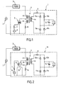
- a device 1 shown inside the dashed frame is powered by an alternating current source, for example by the alternating voltage of an electrical energy network.
- the device 1 is connected in series with a receiver load 3, for example an electrical heating resistor.
- the device comprises a transformer 4 with three windings 4a, 4b, 4c.
- the winding 4a made of small diameter wire has a low impedance compared to the circuit connected downstream.
- the winding 4b made in a small number of turns of large diameter wire, has a very low impedance compared to the receiving load 3, so as to avoid heating.
- the winding 4c made of a large number of small diameter wire turns has a high impedance with respect to the receiving load 3 and with respect to the AC supply voltage 2.
- the transformer 4 with three windings 4a, 4b, 4c has two modes of operation: a voltage transformation mode between the windings 4a, 4c in small diameter wire, and a current transformation mode between the winding 4a in wire of small diameter and the winding 4b in wire of large diameter, intended to feed the receiving load 3.
- the switching between the two operating modes of the transformer 4 is controlled for example by a triac 5 whose trigger is connected to a pulse generator 6, for example a microcontroller 6, with the interposition in series of a resistor 7.
- a relatively large current of between 1 and 20 amperes passes through the winding 4b which magnetizes the circuit and which supplies the receiver load 3, for example an electric heating resistor, to operate the receiver load 3 under conditions nominal, for example to deliver a heating power of between 500 watts and 5 kilowatts.
- the windings 4a and 4c demagnetize the circuit, the winding 4c being fed via a resistor 8 connected in series with the winding 4c to avoid placing this winding 4c in short circuit and to limit a demagnetizing effect of the winding 4c may reduce the demagnetization produced by the winding 4a.
- the three windings 4a, 4b and 4c of the transformer 4 are adjusted by construction to obtain, at the terminals of the winding 4a, neighboring voltages for the two operating modes of the transformer.
- the winding 4a supplies a full-wave rectifier bridge downstream via a smoothing resistor 9.
- the full-wave rectifier bridge with voltage limiter comprises two diodes 10a and 10b and two Zener diodes 11a, 11b.
- the DC voltage supplied by the four-diode rectifier bridge 10a, 10b, 11a, 11b is stabilized by means of a capacitor 12 and supplies a thermostat T or similar load control system 3.
- the switching means of the operation of the transformer 4 are constituted on the Figure 2 by a relay 13 whose contact 14 is controlled by a coil 15 controlled in turn by a pulse generator 6 connected in series with the resistor 7 and the control coil 15.
- the transformer 4 can also switch in this embodiment between two modes of operation: a mode of operation of the supply of the receiver 3 and a standby mode, in which the receiver load 3 is supplied with a low power.
- the power consumption of the circuit represented at Figure 2 is less than one-tenth of the power consumption of the circuit in the operating mode of supply of the load 3 by the transformer 4.
- a third embodiment 1b of the device is connected in series with an AC power supply 2 and a receiver load 3.
- the device of the Figure 3 contains elements that are identical or functionally equivalent to the elements of Figures 1 and 2 and marked with identical reference numbers.
- the device 1b of the Figure 3 differs from device 1 of the Figure 1 by the additional presence of a pulse generator 16 connected in series with a resistor 17 for controlling a triac 18 connected to the resistor 8 in series with the winding 4c of the transformer 4.
- This arrangement allows an increase in the electrical efficiency of the circuit, due to the fact that the triac 18 switches in inverse relation to the triac 5, so as to isolate the winding 4c of the transformer 4 in full power supply operation mode. the receiver load 3.
- the pulse generators 6 and 16 can be obtained by means of inverted outputs of a single microcontroller controlled or forming part of the thermostat T.
- a first device embodiment 1c according to the invention is connected in series with the receiver load 3 and the power supply 2.
- the device 1c of the Figure 4 contains elements that are identical or functionally equivalent to the elements of Figures 1 to 3 and marked with identical reference numbers.
- the device 1c of the Figure 4 differs from the device 1b of the Figure 3 by the presence of an inverter contact 19 controlled by a coil 19a so as to selectively supplying the terminal 20 connected to the common terminal to the windings 4b and 4c, or the terminal 21 connected to the resistor 8 in series with the winding 4c made of a large number of small diameter wire turns.
- the control of the changeover contact 19 is carried out by the pulse generator 6 in series with the resistor 7 and with the coil 19a able to switch the element 19b between the terminal 20 and the terminal 21.
- This arrangement also makes it possible to isolate the winding 4c in the operating mode of power supply at full power of the receiver load 3.
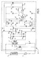
- a second embodiment 1d of the device according to the invention is connected in series with the AC power supply 2 and the receiver load 3.
- the device of the Figure 5 contains elements that are identical or functionally equivalent to the elements of Figures 1 to 4 and marked with identical reference numbers.
- the device of the Figure 5 provides between terminals A and B a simplified thermostat circuit connected to the gate of the triac 5, so as to switch the operation of the transformer 4 between the two modes of operation at full power of the receiving load 3 and the standby mode.
- the thermostat circuit connected downstream of the terminals A and B comprises two transistors 30 and 31, an electric resistor 32, a zener diode 33, a capacitor 34, and resistors 35, 36, 37, 38, a resistor 39 CTN intended by example to indicate the ambient temperature, an adjustable resistor 40 for setting a set temperature, capacitors 41 and 42 and two operational amplifiers 43 and 44.
- the operational amplifier 43 has a positive input connected between the resistors 45 and 46 and a negative input connected to the resistor 47 whose other end is connected to a midpoint between the resistance 39 of temperature measurement and the potentiometer 40 of temperature setpoint.
- the operational amplifier 43 summed these positive and negative inputs and provided an amplified signal depending on the value of the gain resistor 48.
- the amplified signal transmitted by the operational amplifier 43 is connected to a negative input of the hysteresis operational amplifier 44.
- the positive input of the hysteresis amplifier 44 is connected to the midpoint of the resistors 49 and 50 and also receives the loop feedback of the current flowing through the hysteresis resistor 51.
- the hysteresis amplifier 44 thus provides an amplified signal when the difference between the measured temperature and the set temperature is greater than a certain value, so as to avoid the appearance of continuous switching of the power supply in the case a low temperature difference.
- Resistors 52 and 53 are provided downstream of the hysteresis amplifier 44, for supplying the indicator light-emitting diode 54 and for triggering the trigger of the triac 5.
- the ignition of the light-emitting diode 54 thus indicates the operation of the triac 5 and the passage of a large current through the winding 4b made in a small number of turns of large diameter to supply full power to the receiver load 3.
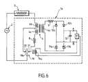
- a third device embodiment 1e according to the invention is connected in series with the receiver load 3 and the power supply 2.
- the device 1e of the figure 6 comprises an inverter contact 19 controlled by a coil 19a so as to selectively supply the terminal 20 connected to the common terminal to the windings 4b and 4c or the terminal 21 connected to the resistor 8 in series with the winding 4c made in a large number of turns of wire of small diameter.
- the control of the changeover contact 19 is effected by a thermostat output T or analogous control system.
- the thermostat T or analog control system may have a very low isolation voltage, without presenting specific protection.
- a receiver load 3 between a full power mode and a low power sleep mode.
- the advantages of the invention obtained for the various embodiments make it possible to reduce the wiring due to the series connection of the device according to the invention with the power supply 2 and the receiver load 3, make it possible to use the magnetic circuit of the device.
- transformer to improve the transfer and the heat dissipation of the power element which provides the switching, allow to improve the speed of establishment of the continuous supply, offer the possibility of connecting the mass of a microcontroller to neutral switching triac and use a full-wave rectification through the galvanic isolation between the primary windings 4b, 4c and the secondary winding 4a.
- the manufacture of the device according to the invention is greatly facilitated by the absence of a bulky polypropylene capacitor, thanks to the possibility of using an internal digital analog converter to a microcontroller to measure a representative value of the AC voltage of the power supply 2 and a value representative of the supply current of the receiver load 3, by measuring the voltage induced on the secondary winding 4a of the device according to the invention.
- These measurements allow a self-adaptability of the regulation coefficients related to the power actually emitted by a receiving charge 3 or a heating body of an electric heater.
- This provision also allows a continuous evaluation of the energy consumed and a power supply without cutting the receiver load or heater 3, while enjoying a steady DC voltage over a wide range of supply voltage 2 and load receiver 3.
- relay 19 allows the power supply 2 to be completely disconnected from the thermostat circuit connected between terminals A and B and thus to use a thermostat having a very low isolation voltage that does not require specific protection
Landscapes
- Engineering & Computer Science (AREA)
- Power Engineering (AREA)
- Control Of Resistance Heating (AREA)
- Control Of Electrical Variables (AREA)
- Emergency Protection Circuit Devices (AREA)
- Push-Button Switches (AREA)
- Relay Circuits (AREA)
- Keying Circuit Devices (AREA)
- Stand-By Power Supply Arrangements (AREA)
Claims (6)
- Vorrichtung zur Stromversorgung einer empfangenden Stelle (3), vor allem eines Heizwiderstands, die einen Transformator (4) mit drei Wicklungen umfasst:eine erste Wicklung (4a) zur Versorgung eines Steuermittels (T), zum Beispiel ein Thermostat (T), wobei die Wicklung im Verhältnis zum nachgeschalteten Kreis eine schwache Impedanz aufweist,eine zweite Wicklung (4b) und eine dritte Wicklung (4c), die mit der empfangenden Stelle und der Quelle zur Versorgung mit Wechselspannung in Reihe geschaltet sind, wobei die zweite Wicklung im Verhältnis zu der empfangenden Stelle (3) eine schwache Impedanz aufweist und die dritte Wicklung im Verhältnis zu der empfangenden Stelle und zu der Versorgungs-Wechselspannung eine starke Impedanz aufweist,wobei die zweite Wicklung (4b) mit einem Umschaltmittel (5, 13, 19) in Reihe geschaltet ist, das imstande ist, die Vorrichtung zwischen einem ersten Funktionsmodus und einem Überwachungsmodus umzuschalten, wobei die Vorrichtung einen Stromumwandlungsmodus zwischen der ersten Wicklung und der zweiten Wicklung im ersten Funktionsmodus und einen Spannungsumwandlungsmodus zwischen der ersten Wicklung und der dritten Wicklung im Überwachungsmodus durchführt,dadurch gekennzeichnet, dass die Vorrichtung ein Isolationsmittel (18, 19) umfasst, das in Reihe mit der dritten Wicklung geschaltet ist und die Isolierung der dritten Wicklung im ersten Funktionsmodus durchführt.
- Vorrichtung nach Anspruch 1, dadurch gekennzeichnet dass das Umschaltmittel am Verbindungspunkt zwischen der zweiten Wicklung (4b) und der dritten Wicklung (4c) des Transformators (4) angeschlossen ist.
- Vorrichtung nach Anspruch 2, dadurch gekennzeichnet, dass das Umschaltmittel (5, 13, 19) einen Triac (5) umfasst.
- Vorrichtung nach Anspruch 2, dadurch gekennzeichnet, dass das Umschaltmittel (5, 13, 19) ein durch Spule (7) gesteuertes Relais (13) mit Kontakt (14) umfasst.
- Vorrichtung nach Anspruch 2, dadurch gekennzeichnet, dass das Isolationsmittel (19) ein Umschaltrelais (19) umfasst.
- Vorrichtung nach Anspruch 2, dadurch gekennzeichnet, dass das Isolationsmittel (18, 19) ein zweites Umschaltmittel (18) umfasst, das imstande ist, die dritte Wicklung (4c) des Transformators (4) im ersten Funktionsmodus derart zu isolieren, dass die empfangende Stelle (3) mit einem hohen Strom versorgt wird, der die zweite Wicklung (4b) des Transformators (4) durchfließt.
Applications Claiming Priority (2)
| Application Number | Priority Date | Filing Date | Title |
|---|---|---|---|
| FR0212220A FR2845532B1 (fr) | 2002-10-03 | 2002-10-03 | Dispositif d'alimentation electrique, notamment d'alimentation d'un commutateur de puissance |
| FR0212220 | 2002-10-03 |
Publications (2)
| Publication Number | Publication Date |
|---|---|
| EP1406374A1 EP1406374A1 (de) | 2004-04-07 |
| EP1406374B1 true EP1406374B1 (de) | 2010-09-22 |
Family
ID=31985410
Family Applications (1)
| Application Number | Title | Priority Date | Filing Date |
|---|---|---|---|
| EP03292445A Expired - Lifetime EP1406374B1 (de) | 2002-10-03 | 2003-10-03 | Elektrische Speisevorrichtung, insbesondere zur Speisung eines Stromschalters |
Country Status (5)
| Country | Link |
|---|---|
| EP (1) | EP1406374B1 (de) |
| AT (1) | ATE482512T1 (de) |
| DE (1) | DE60334270D1 (de) |
| ES (1) | ES2351959T3 (de) |
| FR (1) | FR2845532B1 (de) |
Families Citing this family (2)
| Publication number | Priority date | Publication date | Assignee | Title |
|---|---|---|---|---|
| FR2929020B1 (fr) * | 2008-03-21 | 2010-11-05 | Atlantic Industrie Sas | Dispositif formant thermostat de regulation |
| US9608507B2 (en) | 2013-06-14 | 2017-03-28 | Sinope Technologies Inc. | Low power and low EMI power stealing circuit for a control device |
Family Cites Families (1)
| Publication number | Priority date | Publication date | Assignee | Title |
|---|---|---|---|---|
| US5687068A (en) * | 1995-12-22 | 1997-11-11 | Micro Weiss Electronics, Inc. | Power supply for in-line power controllers and two-terminal electronic thermostat employing same |
-
2002
- 2002-10-03 FR FR0212220A patent/FR2845532B1/fr not_active Expired - Fee Related
-
2003
- 2003-10-03 AT AT03292445T patent/ATE482512T1/de not_active IP Right Cessation
- 2003-10-03 ES ES03292445T patent/ES2351959T3/es not_active Expired - Lifetime
- 2003-10-03 EP EP03292445A patent/EP1406374B1/de not_active Expired - Lifetime
- 2003-10-03 DE DE60334270T patent/DE60334270D1/de not_active Expired - Lifetime
Also Published As
| Publication number | Publication date |
|---|---|
| FR2845532A1 (fr) | 2004-04-09 |
| EP1406374A1 (de) | 2004-04-07 |
| ATE482512T1 (de) | 2010-10-15 |
| ES2351959T3 (es) | 2011-02-14 |
| FR2845532B1 (fr) | 2005-06-24 |
| DE60334270D1 (de) | 2010-11-04 |
Similar Documents
| Publication | Publication Date | Title |
|---|---|---|
| EP0344065A1 (de) | Während der inaktiven Netzschaltungsperiode gespeister elektronischen Regler | |
| FR2568715A1 (fr) | Dispositif de commande d'une bobine d'electroaimant et appareil electrique de commutation equipe d'un tel dispositif | |
| FR2584248A1 (fr) | Circuit de limitation du courant d'appel | |
| FR2746981A1 (fr) | Commande d'un pont mixte au zero de tension | |
| FR2891418A1 (fr) | Dispositif de commande d'alternateur de vehicule | |
| EP1406374B1 (de) | Elektrische Speisevorrichtung, insbesondere zur Speisung eines Stromschalters | |
| EP2742585B1 (de) | Ac/dc-wandler mit galvanischer isolierung und signalkorrektor | |
| FR2613896A1 (fr) | Generateur de fluide chaud a thermo-induction | |
| EP2073367A1 (de) | Wechselspannungsgenerator ausgestattet mit einem Strombegrenzer | |
| EP1750343A1 (de) | Elektronischer Auslöser mit einer Stromversorgungsschaltung einschliesslich Spannungserhöhungsmittel und Leistungschalter mit solchem Auslöser | |
| EP0895443B1 (de) | Einschaltstrombegrenzungsschaltung | |
| FR3092444A1 (fr) | Dispositif domotique de commande électronique à deux fils | |
| EP0843412B1 (de) | Anwesenheitsdetektor mit einer stabilisierten Stromquelle | |
| FR2787648A1 (fr) | Convertisseur d'une haute tension alternative en une basse tension continue | |
| EP1131683B1 (de) | Thermisch verlustarme und spannungsanpassbare logische eingangsschaltung | |
| FR2634601A1 (fr) | Circuit electronique de protection contre les surtensions et les surintensites | |
| FR2467441A1 (fr) | Circuit de commande d'une source lumineuse | |
| EP2198507B1 (de) | Variable steuerung | |
| EP4070455A1 (de) | Aktive entladevorrichtung und -verfahren | |
| FR2825849A1 (fr) | Circuit de commande utilisable avec un convertisseur de puissance a commutation | |
| EP2704303B1 (de) | Kondensatorladeschaltung fuer Phasenanschnittsteuerung | |
| FR2782206A1 (fr) | Convertisseur de tension continu-continu, susceptible d'une protection contre les courts-circuits | |
| FR2849554A1 (fr) | Circuit de commande d'un triac sans isolement galvanique | |
| FR2709890A3 (fr) | Circuit de stabilisation. | |
| FR3155666A1 (fr) | Systeme de conversion d’une premiere tension electrique en une deuxieme tension electrique comprenant au moins un composant passif limiteur de tension |
Legal Events
| Date | Code | Title | Description |
|---|---|---|---|
| PUAI | Public reference made under article 153(3) epc to a published international application that has entered the european phase |
Free format text: ORIGINAL CODE: 0009012 |
|
| AK | Designated contracting states |
Kind code of ref document: A1 Designated state(s): AT BE BG CH CY CZ DE DK EE ES FI FR GB GR HU IE IT LI LU MC NL PT RO SE SI SK TR |
|
| AX | Request for extension of the european patent |
Extension state: AL LT LV MK |
|
| 17P | Request for examination filed |
Effective date: 20040930 |
|
| AKX | Designation fees paid |
Designated state(s): AT BE BG CH CY CZ DE DK EE ES FI FR GB GR HU IE IT LI LU MC NL PT RO SE SI SK TR |
|
| 17Q | First examination report despatched |
Effective date: 20091116 |
|
| GRAP | Despatch of communication of intention to grant a patent |
Free format text: ORIGINAL CODE: EPIDOSNIGR1 |
|
| GRAS | Grant fee paid |
Free format text: ORIGINAL CODE: EPIDOSNIGR3 |
|
| GRAA | (expected) grant |
Free format text: ORIGINAL CODE: 0009210 |
|
| AK | Designated contracting states |
Kind code of ref document: B1 Designated state(s): AT BE BG CH CY CZ DE DK EE ES FI FR GB GR HU IE IT LI LU MC NL PT RO SE SI SK TR |
|
| REG | Reference to a national code |
Ref country code: GB Ref legal event code: FG4D Free format text: NOT ENGLISH |
|
| REG | Reference to a national code |
Ref country code: CH Ref legal event code: EP |
|
| REG | Reference to a national code |
Ref country code: IE Ref legal event code: FG4D Free format text: LANGUAGE OF EP DOCUMENT: FRENCH |
|
| REF | Corresponds to: |
Ref document number: 60334270 Country of ref document: DE Date of ref document: 20101104 Kind code of ref document: P |
|
| PG25 | Lapsed in a contracting state [announced via postgrant information from national office to epo] |
Ref country code: FI Free format text: LAPSE BECAUSE OF FAILURE TO SUBMIT A TRANSLATION OF THE DESCRIPTION OR TO PAY THE FEE WITHIN THE PRESCRIBED TIME-LIMIT Effective date: 20100922 Ref country code: AT Free format text: LAPSE BECAUSE OF FAILURE TO SUBMIT A TRANSLATION OF THE DESCRIPTION OR TO PAY THE FEE WITHIN THE PRESCRIBED TIME-LIMIT Effective date: 20100922 |
|
| REG | Reference to a national code |
Ref country code: NL Ref legal event code: VDEP Effective date: 20100922 |
|
| REG | Reference to a national code |
Ref country code: ES Ref legal event code: FG2A Effective date: 20110202 |
|
| PG25 | Lapsed in a contracting state [announced via postgrant information from national office to epo] |
Ref country code: SI Free format text: LAPSE BECAUSE OF FAILURE TO SUBMIT A TRANSLATION OF THE DESCRIPTION OR TO PAY THE FEE WITHIN THE PRESCRIBED TIME-LIMIT Effective date: 20100922 |
|
| PG25 | Lapsed in a contracting state [announced via postgrant information from national office to epo] |
Ref country code: GR Free format text: LAPSE BECAUSE OF FAILURE TO SUBMIT A TRANSLATION OF THE DESCRIPTION OR TO PAY THE FEE WITHIN THE PRESCRIBED TIME-LIMIT Effective date: 20101223 Ref country code: SE Free format text: LAPSE BECAUSE OF FAILURE TO SUBMIT A TRANSLATION OF THE DESCRIPTION OR TO PAY THE FEE WITHIN THE PRESCRIBED TIME-LIMIT Effective date: 20100922 |
|
| REG | Reference to a national code |
Ref country code: IE Ref legal event code: FD4D |
|
| PG25 | Lapsed in a contracting state [announced via postgrant information from national office to epo] |
Ref country code: IE Free format text: LAPSE BECAUSE OF FAILURE TO SUBMIT A TRANSLATION OF THE DESCRIPTION OR TO PAY THE FEE WITHIN THE PRESCRIBED TIME-LIMIT Effective date: 20100922 |
|
| PG25 | Lapsed in a contracting state [announced via postgrant information from national office to epo] |
Ref country code: CZ Free format text: LAPSE BECAUSE OF FAILURE TO SUBMIT A TRANSLATION OF THE DESCRIPTION OR TO PAY THE FEE WITHIN THE PRESCRIBED TIME-LIMIT Effective date: 20100922 Ref country code: IT Free format text: LAPSE BECAUSE OF FAILURE TO SUBMIT A TRANSLATION OF THE DESCRIPTION OR TO PAY THE FEE WITHIN THE PRESCRIBED TIME-LIMIT Effective date: 20100922 Ref country code: MC Free format text: LAPSE BECAUSE OF NON-PAYMENT OF DUE FEES Effective date: 20101031 Ref country code: PT Free format text: LAPSE BECAUSE OF FAILURE TO SUBMIT A TRANSLATION OF THE DESCRIPTION OR TO PAY THE FEE WITHIN THE PRESCRIBED TIME-LIMIT Effective date: 20110124 Ref country code: SK Free format text: LAPSE BECAUSE OF FAILURE TO SUBMIT A TRANSLATION OF THE DESCRIPTION OR TO PAY THE FEE WITHIN THE PRESCRIBED TIME-LIMIT Effective date: 20100922 Ref country code: EE Free format text: LAPSE BECAUSE OF FAILURE TO SUBMIT A TRANSLATION OF THE DESCRIPTION OR TO PAY THE FEE WITHIN THE PRESCRIBED TIME-LIMIT Effective date: 20100922 Ref country code: RO Free format text: LAPSE BECAUSE OF FAILURE TO SUBMIT A TRANSLATION OF THE DESCRIPTION OR TO PAY THE FEE WITHIN THE PRESCRIBED TIME-LIMIT Effective date: 20100922 Ref country code: NL Free format text: LAPSE BECAUSE OF FAILURE TO SUBMIT A TRANSLATION OF THE DESCRIPTION OR TO PAY THE FEE WITHIN THE PRESCRIBED TIME-LIMIT Effective date: 20100922 |
|
| REG | Reference to a national code |
Ref country code: CH Ref legal event code: PL |
|
| PG25 | Lapsed in a contracting state [announced via postgrant information from national office to epo] |
Ref country code: LI Free format text: LAPSE BECAUSE OF NON-PAYMENT OF DUE FEES Effective date: 20101031 Ref country code: CH Free format text: LAPSE BECAUSE OF NON-PAYMENT OF DUE FEES Effective date: 20101031 |
|
| PLBE | No opposition filed within time limit |
Free format text: ORIGINAL CODE: 0009261 |
|
| STAA | Information on the status of an ep patent application or granted ep patent |
Free format text: STATUS: NO OPPOSITION FILED WITHIN TIME LIMIT |
|
| GBPC | Gb: european patent ceased through non-payment of renewal fee |
Effective date: 20101222 |
|
| 26N | No opposition filed |
Effective date: 20110623 |
|
| PG25 | Lapsed in a contracting state [announced via postgrant information from national office to epo] |
Ref country code: DK Free format text: LAPSE BECAUSE OF FAILURE TO SUBMIT A TRANSLATION OF THE DESCRIPTION OR TO PAY THE FEE WITHIN THE PRESCRIBED TIME-LIMIT Effective date: 20100922 |
|
| REG | Reference to a national code |
Ref country code: DE Ref legal event code: R119 Ref document number: 60334270 Country of ref document: DE Effective date: 20110502 |
|
| PG25 | Lapsed in a contracting state [announced via postgrant information from national office to epo] |
Ref country code: GB Free format text: LAPSE BECAUSE OF NON-PAYMENT OF DUE FEES Effective date: 20101222 |
|
| PG25 | Lapsed in a contracting state [announced via postgrant information from national office to epo] |
Ref country code: CY Free format text: LAPSE BECAUSE OF FAILURE TO SUBMIT A TRANSLATION OF THE DESCRIPTION OR TO PAY THE FEE WITHIN THE PRESCRIBED TIME-LIMIT Effective date: 20100922 |
|
| PG25 | Lapsed in a contracting state [announced via postgrant information from national office to epo] |
Ref country code: LU Free format text: LAPSE BECAUSE OF NON-PAYMENT OF DUE FEES Effective date: 20101003 Ref country code: HU Free format text: LAPSE BECAUSE OF FAILURE TO SUBMIT A TRANSLATION OF THE DESCRIPTION OR TO PAY THE FEE WITHIN THE PRESCRIBED TIME-LIMIT Effective date: 20110323 Ref country code: BG Free format text: LAPSE BECAUSE OF FAILURE TO SUBMIT A TRANSLATION OF THE DESCRIPTION OR TO PAY THE FEE WITHIN THE PRESCRIBED TIME-LIMIT Effective date: 20100922 |
|
| PG25 | Lapsed in a contracting state [announced via postgrant information from national office to epo] |
Ref country code: TR Free format text: LAPSE BECAUSE OF FAILURE TO SUBMIT A TRANSLATION OF THE DESCRIPTION OR TO PAY THE FEE WITHIN THE PRESCRIBED TIME-LIMIT Effective date: 20100922 |
|
| PGFP | Annual fee paid to national office [announced via postgrant information from national office to epo] |
Ref country code: FR Payment date: 20121031 Year of fee payment: 10 Ref country code: BE Payment date: 20121022 Year of fee payment: 10 |
|
| PGFP | Annual fee paid to national office [announced via postgrant information from national office to epo] |
Ref country code: ES Payment date: 20121026 Year of fee payment: 10 |
|
| PG25 | Lapsed in a contracting state [announced via postgrant information from national office to epo] |
Ref country code: DE Free format text: LAPSE BECAUSE OF NON-PAYMENT OF DUE FEES Effective date: 20110502 |
|
| PG25 | Lapsed in a contracting state [announced via postgrant information from national office to epo] |
Ref country code: BG Free format text: LAPSE BECAUSE OF FAILURE TO SUBMIT A TRANSLATION OF THE DESCRIPTION OR TO PAY THE FEE WITHIN THE PRESCRIBED TIME-LIMIT Effective date: 20101222 |
|
| BERE | Be: lapsed |
Owner name: ATLANTIC INDUSTRIE Effective date: 20131031 |
|
| REG | Reference to a national code |
Ref country code: FR Ref legal event code: ST Effective date: 20140630 |
|
| PG25 | Lapsed in a contracting state [announced via postgrant information from national office to epo] |
Ref country code: FR Free format text: LAPSE BECAUSE OF NON-PAYMENT OF DUE FEES Effective date: 20131031 |
|
| PG25 | Lapsed in a contracting state [announced via postgrant information from national office to epo] |
Ref country code: BE Free format text: LAPSE BECAUSE OF NON-PAYMENT OF DUE FEES Effective date: 20131031 |
|
| REG | Reference to a national code |
Ref country code: ES Ref legal event code: FD2A Effective date: 20150709 |
|
| PG25 | Lapsed in a contracting state [announced via postgrant information from national office to epo] |
Ref country code: ES Free format text: LAPSE BECAUSE OF NON-PAYMENT OF DUE FEES Effective date: 20131004 |