EP2667017A1 - An aligning tool in the field of wind turbines for aligning a hole with a fastener - Google Patents
An aligning tool in the field of wind turbines for aligning a hole with a fastener Download PDFInfo
- Publication number
- EP2667017A1 EP2667017A1 EP12168844.4A EP12168844A EP2667017A1 EP 2667017 A1 EP2667017 A1 EP 2667017A1 EP 12168844 A EP12168844 A EP 12168844A EP 2667017 A1 EP2667017 A1 EP 2667017A1
- Authority
- EP
- European Patent Office
- Prior art keywords
- fastener
- section
- hole
- aligning tool
- aligning
- Prior art date
- Legal status (The legal status is an assumption and is not a legal conclusion. Google has not performed a legal analysis and makes no representation as to the accuracy of the status listed.)
- Granted
Links
- 238000000034 method Methods 0.000 claims abstract description 5
- 238000003780 insertion Methods 0.000 claims description 9
- 230000037431 insertion Effects 0.000 claims description 9
- 238000009434 installation Methods 0.000 description 3
- 229920002430 Fibre-reinforced plastic Polymers 0.000 description 1
- 229910000831 Steel Inorganic materials 0.000 description 1
- 239000011151 fibre-reinforced plastic Substances 0.000 description 1
- 238000012986 modification Methods 0.000 description 1
- 230000004048 modification Effects 0.000 description 1
- 239000004033 plastic Substances 0.000 description 1
- 229920003023 plastic Polymers 0.000 description 1
- 239000010959 steel Substances 0.000 description 1
Images
Classifications
-
- B—PERFORMING OPERATIONS; TRANSPORTING
- B23—MACHINE TOOLS; METAL-WORKING NOT OTHERWISE PROVIDED FOR
- B23P—METAL-WORKING NOT OTHERWISE PROVIDED FOR; COMBINED OPERATIONS; UNIVERSAL MACHINE TOOLS
- B23P19/00—Machines for simply fitting together or separating metal parts or objects, or metal and non-metal parts, whether or not involving some deformation; Tools or devices therefor so far as not provided for in other classes
- B23P19/10—Aligning parts to be fitted together
- B23P19/12—Alignment of parts for insertion into bores
-
- F—MECHANICAL ENGINEERING; LIGHTING; HEATING; WEAPONS; BLASTING
- F03—MACHINES OR ENGINES FOR LIQUIDS; WIND, SPRING, OR WEIGHT MOTORS; PRODUCING MECHANICAL POWER OR A REACTIVE PROPULSIVE THRUST, NOT OTHERWISE PROVIDED FOR
- F03D—WIND MOTORS
- F03D13/00—Assembly, mounting or commissioning of wind motors; Arrangements specially adapted for transporting wind motor components
- F03D13/10—Assembly of wind motors; Arrangements for erecting wind motors
-
- F—MECHANICAL ENGINEERING; LIGHTING; HEATING; WEAPONS; BLASTING
- F03—MACHINES OR ENGINES FOR LIQUIDS; WIND, SPRING, OR WEIGHT MOTORS; PRODUCING MECHANICAL POWER OR A REACTIVE PROPULSIVE THRUST, NOT OTHERWISE PROVIDED FOR
- F03D—WIND MOTORS
- F03D13/00—Assembly, mounting or commissioning of wind motors; Arrangements specially adapted for transporting wind motor components
- F03D13/20—Arrangements for mounting or supporting wind motors; Masts or towers for wind motors
- F03D13/22—Foundations specially adapted for wind motors
-
- F—MECHANICAL ENGINEERING; LIGHTING; HEATING; WEAPONS; BLASTING
- F05—INDEXING SCHEMES RELATING TO ENGINES OR PUMPS IN VARIOUS SUBCLASSES OF CLASSES F01-F04
- F05B—INDEXING SCHEME RELATING TO WIND, SPRING, WEIGHT, INERTIA OR LIKE MOTORS, TO MACHINES OR ENGINES FOR LIQUIDS COVERED BY SUBCLASSES F03B, F03D AND F03G
- F05B2230/00—Manufacture
- F05B2230/60—Assembly methods
- F05B2230/604—Assembly methods using positioning or alignment devices for aligning or centering, e.g. pins
-
- F—MECHANICAL ENGINEERING; LIGHTING; HEATING; WEAPONS; BLASTING
- F16—ENGINEERING ELEMENTS AND UNITS; GENERAL MEASURES FOR PRODUCING AND MAINTAINING EFFECTIVE FUNCTIONING OF MACHINES OR INSTALLATIONS; THERMAL INSULATION IN GENERAL
- F16B—DEVICES FOR FASTENING OR SECURING CONSTRUCTIONAL ELEMENTS OR MACHINE PARTS TOGETHER, e.g. NAILS, BOLTS, CIRCLIPS, CLAMPS, CLIPS OR WEDGES; JOINTS OR JOINTING
- F16B19/00—Bolts without screw-thread; Pins, including deformable elements; Rivets
- F16B19/02—Bolts or sleeves for positioning of machine parts, e.g. notched taper pins, fitting pins, sleeves, eccentric positioning rings
-
- F—MECHANICAL ENGINEERING; LIGHTING; HEATING; WEAPONS; BLASTING
- F16—ENGINEERING ELEMENTS AND UNITS; GENERAL MEASURES FOR PRODUCING AND MAINTAINING EFFECTIVE FUNCTIONING OF MACHINES OR INSTALLATIONS; THERMAL INSULATION IN GENERAL
- F16B—DEVICES FOR FASTENING OR SECURING CONSTRUCTIONAL ELEMENTS OR MACHINE PARTS TOGETHER, e.g. NAILS, BOLTS, CIRCLIPS, CLAMPS, CLIPS OR WEDGES; JOINTS OR JOINTING
- F16B37/00—Nuts or like thread-engaging members
- F16B37/14—Cap nuts; Nut caps or bolt caps
-
- Y—GENERAL TAGGING OF NEW TECHNOLOGICAL DEVELOPMENTS; GENERAL TAGGING OF CROSS-SECTIONAL TECHNOLOGIES SPANNING OVER SEVERAL SECTIONS OF THE IPC; TECHNICAL SUBJECTS COVERED BY FORMER USPC CROSS-REFERENCE ART COLLECTIONS [XRACs] AND DIGESTS
- Y02—TECHNOLOGIES OR APPLICATIONS FOR MITIGATION OR ADAPTATION AGAINST CLIMATE CHANGE
- Y02E—REDUCTION OF GREENHOUSE GAS [GHG] EMISSIONS, RELATED TO ENERGY GENERATION, TRANSMISSION OR DISTRIBUTION
- Y02E10/00—Energy generation through renewable energy sources
- Y02E10/70—Wind energy
- Y02E10/72—Wind turbines with rotation axis in wind direction
-
- Y—GENERAL TAGGING OF NEW TECHNOLOGICAL DEVELOPMENTS; GENERAL TAGGING OF CROSS-SECTIONAL TECHNOLOGIES SPANNING OVER SEVERAL SECTIONS OF THE IPC; TECHNICAL SUBJECTS COVERED BY FORMER USPC CROSS-REFERENCE ART COLLECTIONS [XRACs] AND DIGESTS
- Y02—TECHNOLOGIES OR APPLICATIONS FOR MITIGATION OR ADAPTATION AGAINST CLIMATE CHANGE
- Y02E—REDUCTION OF GREENHOUSE GAS [GHG] EMISSIONS, RELATED TO ENERGY GENERATION, TRANSMISSION OR DISTRIBUTION
- Y02E10/00—Energy generation through renewable energy sources
- Y02E10/70—Wind energy
- Y02E10/728—Onshore wind turbines
-
- Y—GENERAL TAGGING OF NEW TECHNOLOGICAL DEVELOPMENTS; GENERAL TAGGING OF CROSS-SECTIONAL TECHNOLOGIES SPANNING OVER SEVERAL SECTIONS OF THE IPC; TECHNICAL SUBJECTS COVERED BY FORMER USPC CROSS-REFERENCE ART COLLECTIONS [XRACs] AND DIGESTS
- Y02—TECHNOLOGIES OR APPLICATIONS FOR MITIGATION OR ADAPTATION AGAINST CLIMATE CHANGE
- Y02P—CLIMATE CHANGE MITIGATION TECHNOLOGIES IN THE PRODUCTION OR PROCESSING OF GOODS
- Y02P70/00—Climate change mitigation technologies in the production process for final industrial or consumer products
- Y02P70/50—Manufacturing or production processes characterised by the final manufactured product
-
- Y—GENERAL TAGGING OF NEW TECHNOLOGICAL DEVELOPMENTS; GENERAL TAGGING OF CROSS-SECTIONAL TECHNOLOGIES SPANNING OVER SEVERAL SECTIONS OF THE IPC; TECHNICAL SUBJECTS COVERED BY FORMER USPC CROSS-REFERENCE ART COLLECTIONS [XRACs] AND DIGESTS
- Y10—TECHNICAL SUBJECTS COVERED BY FORMER USPC
- Y10T—TECHNICAL SUBJECTS COVERED BY FORMER US CLASSIFICATION
- Y10T29/00—Metal working
- Y10T29/49—Method of mechanical manufacture
- Y10T29/49826—Assembling or joining
- Y10T29/49895—Associating parts by use of aligning means [e.g., use of a drift pin or a "fixture"]
-
- Y—GENERAL TAGGING OF NEW TECHNOLOGICAL DEVELOPMENTS; GENERAL TAGGING OF CROSS-SECTIONAL TECHNOLOGIES SPANNING OVER SEVERAL SECTIONS OF THE IPC; TECHNICAL SUBJECTS COVERED BY FORMER USPC CROSS-REFERENCE ART COLLECTIONS [XRACs] AND DIGESTS
- Y10—TECHNICAL SUBJECTS COVERED BY FORMER USPC
- Y10T—TECHNICAL SUBJECTS COVERED BY FORMER US CLASSIFICATION
- Y10T29/00—Metal working
- Y10T29/53—Means to assemble or disassemble
- Y10T29/53909—Means comprising hand manipulatable tool
- Y10T29/53913—Aligner or center
Definitions
- the present invention relates to an aligning tool in the field of wind turbines for aligning a hole with a fastener for insertion of the fastener into the hole.
- a wind turbine comprises a tower which is installed on a foundation.
- the foundation comprises a large number of bolts protruding upwards. These bolts have to fit through the same number of through-holes in one or more flanges of the tower. Due to the large number of bolts that need to be aligned with their corresponding through-holes, the installation of the tower on the foundation can be difficult and time-consuming. In the past, the installation required many small turns of the tower with respect to the foundation in order to align the bolts and the through-holes.
- an aligning tool in the field of wind turbines for aligning a hole with a fastener for insertion of the fastener into the hole.
- the aligning tool comprises a first section adapted for connecting to the fastener and a second section having an outside diameter tapering down in a direction away from the first section.
- the second section thus has one end having a smaller outside diameter than the other end.
- diameter refers to the largest chord of a cross-section of the corresponding element (hole, fastener or aligning tool).
- the cross-section of the element may be circular, rectangular or square, for example.
- the smaller outside diameter is smaller than the inside diameter of the hole which the aligning tool aligns with the fastener. The end with the smaller outside diameter will thus easily catch the corresponding hole.
- one or more of the bolts mentioned in the introductory section may each be fitted with an aligning tool in accordance with the invention in a first step.
- the tower is installed, wherein one or more of the corresponding holes in the flange of the tower are caught by a corresponding aligning tool.
- each aligning tool forces the corresponding holes to become more and more aligned with each corresponding bolt. As one or more of the holes become aligned with their corresponding bolts, the rest of the holes will then follow to fit the rest of the bolts.
- the first section comprises a receptacle to receive the fastener.
- the receptacle may be formed as a plain sleeve.
- the receptacle is configured so as to receive the fastener in a snug manner.
- the first section comprises an inner thread adapted to be screwed onto the fastener.
- the aligning tool can be connected to the fastener in an easy manner.
- the first section will be screwed only onto an end portion of the fastener.
- the inner thread may be formed on the inside of the receptacle to receive the fastener.
- the aligning tool comprises a geometry adapted to apply a torque for screwing the first section onto the fastener. This simplifies the mounting of the aligning tool on a corresponding fastener.
- the geometry is adapted to come into engagement with a wrench or screwdriver.
- the geometry may be adapted to fit with a socket wrench, a single-ended wrench, a flat-tip screwdriver or a Phillips screwdriver.
- the geometry is formed as a hexagon head.
- a socket wrench with a hexagon-shaped socket may be used for applying a torque to the hexagon head.
- the hexagon head forms an end of the second section pointing away from the first section.
- the hexagon head forms a tip of the aligning tool.
- a set in the field of wind turbines comprises a first part comprising at least one fastener, a second part comprising at least one hole and an aligning tool in accordance with the present invention, the aligning tool being adapted to align the at least one hole and the at least one fastener for insertion of the at least one fastener into the at least one hole.
- the "field of wind turbines” presently also covers foundations of wind turbines as well as other objects attached to wind turbines.
- the second section of the aligning tool has a first outside diameter corresponding to the inside diameter of the hole, and a second outside diameter smaller than the first outside diameter, the second section tapering down from the first to the second diameter.
- the second outside diameter of the second section is much smaller than the inside diameter of the hole.
- the second outside diameter of the second section may be half or a third of the diameter of the hole, or smaller.
- the first part is a foundation of a wind turbine and the second part is a section of a tower of the wind turbine.
- the one or more aligning tools are used to connect the foundation to the tower.
- the first part is a first section of a tower of a wind turbine and the second part is a second section of the tower.
- the one or more aligning tools are used to connect two sections of a tower to each other.
- the fastener is a bolt, a screw, a stud or a pin.
- the fastener may or may not have an outer thread in that portion that the aligning tool is connected to for the alignment process.
- the first section may comprise a sleeve which fits snugly onto the portion of the fastener not having an outer thread.
- the fastener has a first and second portion, the second portion having a smaller diameter than the first portion and, in one embodiment, an outer thread. The first section of the aligning tool is connected to the second portion.
- the foundation has at least one row of circularly arranged bolts and the first section of the tower has at least one row of circularly arranged holes, wherein at least one aligning tool is screwed onto a bolt.
- the first section will have an inside and an outside flange, each flange comprising a row of circularly arranged holes.
- the foundation is also provided with two rows of circularly arranged bolts fitting to the first and the second row of holes, respectively. Two or more aligning tools may typically be used.
- an aligning tool for aligning a hole and a fastener for insertion of the fastener into the hole in the field of wind turbines.
- a method for assembling a wind turbine wherein a hole and a fastener are aligned for insertion of the fastener into the hole using an aligning tool in accordance with the invention.
- a tower of a wind turbine may be connected to a foundation of the wind turbine using the method.
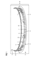
- Fig. 1 shows in a perspective, partial view a wind turbine 1 being assembled.
- Fig. 1 shows a first step.
- the wind turbine 1 comprises a first part in the form of a foundation 2 and a second part in the form of a tower 3.
- the foundation 2 comprises an inner row 4 and an outer row 5 of fasteners in the form of bolts 6.
- Fig. 1 only shows a threaded shank 7 of each bolt 6 sticking out upwards from a concrete body 11 of the foundation 2.
- a number of aligning tools 12 are provided. Each aligning tool 12 is attached to a respective bolt 6. For example, an aligning tool 12 may be attached to every tenth bolt of the outer row 5.
- the foundation 2, the tower 3 and the aligning tools 12 form together a set 10.
- the tower 3 comprises an outer flange 13 at its lower end. Also, the tower 3 comprises an inner flange which is however not shown in Fig. 1 .
- the outer flange 13 has a row 14 of holes 15, each hole 15 corresponding to a bolt 6 in the outer row 5 of the foundation 2.
- the holes 15 are formed as through-holes.
- the inner flange (not shown) comprises a row of holes, each hole corresponding to a bolt 6 in the inner row 4 of the foundation 2.
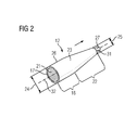
- Fig. 2 is a perspective view of one of the aligning tools 12 from Fig. 1 .
- the aligning tool 12 comprises a first section 16 adapted for connecting to a threaded shank 7 of a bolt 6.
- the first section 16 has a sleeve-shaped receptacle 17, comprising an inner thread 21.
- the inner thread 21 corresponds to the outer thread of the shank 7 of a bolt 6.
- the aligning tool 12 comprises a second section 22 adjoining the first section 16.
- the second section 22 tapers down in a direction (indicated with an arrow in Fig. 2 ) away from the first section 16.
- the section 22 has a first end 23 having an outer diameter 24.
- the outer diameter 24 is the same as the outer diameter of the first section 16 and is configured to provide a clearance fit with a hole 15 in the flange 13 of the tower 3.
- the second section 22 tapers down from the outer diameter 24 to an outer diameter 25.
- the outer diameter 25 is much smaller than the outer diameter 24, and thus much smaller than the diameter of the hole 15.
- the outer diameter 25 can be a third of the outer diameter 24.
- the first and second section 16, 22 are formed in one piece and have an outer rocket-shaped surface 26.
- the aligning tool 12 comprises a geometry 27 adapted to apply a torque to the aligning tool 12 for screwing the inner thread 21 onto the shank 7 of a bolt 6.
- the geometry 27 is formed as a hexagon head, for example.
- the hexagon head 27 is adapted to come into engagement with a socket wrench, in particular.
- the hexagon head 27 may attach to a second end 31 of the second section 22 facing away from the first section 16.
- the hexagon head 27 has an outer diameter smaller or equal to the outer diameter 25.
- the hexagon head 27 may be formed in one piece with the section 22.
- the aligning tool 12 can be made of steel or plastic, in particular fiber-reinforced plastic.
- the aligning tools 12 are screwed onto the shank 7 of a respective bolt 6 using a socket wrench (not shown), for example.
- each hole 15 is centered with respect to a center line 32 of each aligning tool 12 as the tower 3 is lowered more and more towards the foundation 2.
- each hole 15 is centered with respect to each bolt 6.
- the aligning tools 12 may also or instead be attached to bolts 6 of the inner row 4 (see Fig. 1 ). Further, the aligning tools 12 may be used in connection with other fasteners, for example pins, which do not have an outer thread. In this case, the receptacle 17 of each aligning tool 12 may be formed without the inner thread 21.
Abstract
Description
- An aligning tool in the field of wind turbines for aligning a hole with a fastener
- The present invention relates to an aligning tool in the field of wind turbines for aligning a hole with a fastener for insertion of the fastener into the hole.
- Generally, a wind turbine comprises a tower which is installed on a foundation. The foundation comprises a large number of bolts protruding upwards. These bolts have to fit through the same number of through-holes in one or more flanges of the tower. Due to the large number of bolts that need to be aligned with their corresponding through-holes, the installation of the tower on the foundation can be difficult and time-consuming. In the past, the installation required many small turns of the tower with respect to the foundation in order to align the bolts and the through-holes.
- It is one objective of the present invention to provide an approach for easy alignment of a hole and a fastener in the field of wind turbines.
- Accordingly, an aligning tool in the field of wind turbines for aligning a hole with a fastener for insertion of the fastener into the hole is provided. The aligning tool comprises a first section adapted for connecting to the fastener and a second section having an outside diameter tapering down in a direction away from the first section.
- The second section thus has one end having a smaller outside diameter than the other end. Herein, "diameter" refers to the largest chord of a cross-section of the corresponding element (hole, fastener or aligning tool). The cross-section of the element may be circular, rectangular or square, for example. The smaller outside diameter is smaller than the inside diameter of the hole which the aligning tool aligns with the fastener. The end with the smaller outside diameter will thus easily catch the corresponding hole. For example, one or more of the bolts mentioned in the introductory section may each be fitted with an aligning tool in accordance with the invention in a first step. In a second step, the tower is installed, wherein one or more of the corresponding holes in the flange of the tower are caught by a corresponding aligning tool. When the tower is lowered in a third step, the increasing outside diameter of each aligning tool forces the corresponding holes to become more and more aligned with each corresponding bolt. As one or more of the holes become aligned with their corresponding bolts, the rest of the holes will then follow to fit the rest of the bolts.
- According to an embodiment, the first section comprises a receptacle to receive the fastener. The receptacle may be formed as a plain sleeve. Preferably, the receptacle is configured so as to receive the fastener in a snug manner.
- According to a further embodiment, the first section comprises an inner thread adapted to be screwed onto the fastener. Thus, the aligning tool can be connected to the fastener in an easy manner. Typically, the first section will be screwed only onto an end portion of the fastener. The inner thread may be formed on the inside of the receptacle to receive the fastener.
- According to a further embodiment, the aligning tool comprises a geometry adapted to apply a torque for screwing the first section onto the fastener. This simplifies the mounting of the aligning tool on a corresponding fastener.
- According to a further embodiment, the geometry is adapted to come into engagement with a wrench or screwdriver. In particular, the geometry may be adapted to fit with a socket wrench, a single-ended wrench, a flat-tip screwdriver or a Phillips screwdriver.
- According to a further embodiment, the geometry is formed as a hexagon head. Thus, for example a socket wrench with a hexagon-shaped socket may be used for applying a torque to the hexagon head.
- According to a further embodiment, the hexagon head forms an end of the second section pointing away from the first section. Thus, the hexagon head forms a tip of the aligning tool.
- Further, a set in the field of wind turbines is provided. The set comprises a first part comprising at least one fastener, a second part comprising at least one hole and an aligning tool in accordance with the present invention, the aligning tool being adapted to align the at least one hole and the at least one fastener for insertion of the at least one fastener into the at least one hole.
- The "field of wind turbines" presently also covers foundations of wind turbines as well as other objects attached to wind turbines.
- According to an embodiment, the second section of the aligning tool has a first outside diameter corresponding to the inside diameter of the hole, and a second outside diameter smaller than the first outside diameter, the second section tapering down from the first to the second diameter. Typically, the second outside diameter of the second section is much smaller than the inside diameter of the hole. For example, the second outside diameter of the second section may be half or a third of the diameter of the hole, or smaller.
- According to a further embodiment, the first part is a foundation of a wind turbine and the second part is a section of a tower of the wind turbine. Thus, the one or more aligning tools are used to connect the foundation to the tower. According to a further embodiment, the first part is a first section of a tower of a wind turbine and the second part is a second section of the tower. Thus, in this embodiment, the one or more aligning tools are used to connect two sections of a tower to each other.
- According to a further embodiment, the fastener is a bolt, a screw, a stud or a pin. Generally speaking, the fastener may or may not have an outer thread in that portion that the aligning tool is connected to for the alignment process. In the case where the fastener does not have an outside thread, the first section may comprise a sleeve which fits snugly onto the portion of the fastener not having an outer thread. According to another embodiment, the fastener has a first and second portion, the second portion having a smaller diameter than the first portion and, in one embodiment, an outer thread. The first section of the aligning tool is connected to the second portion.
- According to a further embodiment, the foundation has at least one row of circularly arranged bolts and the first section of the tower has at least one row of circularly arranged holes, wherein at least one aligning tool is screwed onto a bolt. Typically, the first section will have an inside and an outside flange, each flange comprising a row of circularly arranged holes. In this case, the foundation is also provided with two rows of circularly arranged bolts fitting to the first and the second row of holes, respectively. Two or more aligning tools may typically be used.
- Further, a use of an aligning tool according to the present invention is provided for aligning a hole and a fastener for insertion of the fastener into the hole in the field of wind turbines.
- Also, a method for assembling a wind turbine is provided, wherein a hole and a fastener are aligned for insertion of the fastener into the hole using an aligning tool in accordance with the invention.
- For example, a tower of a wind turbine may be connected to a foundation of the wind turbine using the method.
- Further objects, features and advantages of the present invention will become apparent from the subsequent description and depending claims, taken in conjunction with the accompanying drawings, in which:
-
Fig. 1 is a perspective, partial view of a wind turbine tower being mounted to a foundation according to a first step in one embodiment; -
Fig. 2 illustrates in a perspective view an aligning tool fromFig. 1 ; -
Figs. 3 and4 are perspective views of the tower and foundation fromFig. 1 according to a second and third step. - In the Figures, like reference numerals designate like or functionally equivalents elements, unless otherwise indicated.
-
Fig. 1 shows in a perspective, partial view awind turbine 1 being assembled.Fig. 1 shows a first step. - The
wind turbine 1 comprises a first part in the form of afoundation 2 and a second part in the form of atower 3. - The
foundation 2 comprises aninner row 4 and an outer row 5 of fasteners in the form ofbolts 6. In fact,Fig. 1 only shows a threaded shank 7 of eachbolt 6 sticking out upwards from aconcrete body 11 of thefoundation 2. - A number of aligning
tools 12 are provided. Each aligningtool 12 is attached to arespective bolt 6. For example, an aligningtool 12 may be attached to every tenth bolt of the outer row 5. Thefoundation 2, thetower 3 and the aligningtools 12 form together a set 10. - The
tower 3 comprises anouter flange 13 at its lower end. Also, thetower 3 comprises an inner flange which is however not shown inFig. 1 . - The
outer flange 13 has arow 14 ofholes 15, eachhole 15 corresponding to abolt 6 in the outer row 5 of thefoundation 2. Theholes 15 are formed as through-holes. Likewise, the inner flange (not shown) comprises a row of holes, each hole corresponding to abolt 6 in theinner row 4 of thefoundation 2. -
Fig. 2 is a perspective view of one of the aligningtools 12 fromFig. 1 . - The aligning
tool 12 comprises afirst section 16 adapted for connecting to a threaded shank 7 of abolt 6. To this end, thefirst section 16 has a sleeve-shapedreceptacle 17, comprising aninner thread 21. Theinner thread 21 corresponds to the outer thread of the shank 7 of abolt 6. - Further, the aligning
tool 12 comprises asecond section 22 adjoining thefirst section 16. Thesecond section 22 tapers down in a direction (indicated with an arrow inFig. 2 ) away from thefirst section 16. Thesection 22 has afirst end 23 having anouter diameter 24. Theouter diameter 24 is the same as the outer diameter of thefirst section 16 and is configured to provide a clearance fit with ahole 15 in theflange 13 of thetower 3. Thesecond section 22 tapers down from theouter diameter 24 to anouter diameter 25. Theouter diameter 25 is much smaller than theouter diameter 24, and thus much smaller than the diameter of thehole 15. For example, theouter diameter 25 can be a third of theouter diameter 24. - Preferably, the first and
second section surface 26. - Further, the aligning
tool 12 comprises ageometry 27 adapted to apply a torque to the aligningtool 12 for screwing theinner thread 21 onto the shank 7 of abolt 6. Thegeometry 27 is formed as a hexagon head, for example. Thehexagon head 27 is adapted to come into engagement with a socket wrench, in particular. Thehexagon head 27 may attach to asecond end 31 of thesecond section 22 facing away from thefirst section 16. Thehexagon head 27 has an outer diameter smaller or equal to theouter diameter 25. Also, thehexagon head 27 may be formed in one piece with thesection 22. - The aligning
tool 12 can be made of steel or plastic, in particular fiber-reinforced plastic. - Returning to
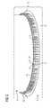
Fig. 1 , it can be seen that, first, the aligningtools 12 are screwed onto the shank 7 of arespective bolt 6 using a socket wrench (not shown), for example. - Thereafter, the
tower 3 is lowered towards thefoundation 2. Since theend 31 of each aligning tool 12 (as well as thehexagon head 27, if provided) has the smallouter diameter 25, the end 31 (or the hexagon head 27) easily catches a correspondinghole 15 in theflange 13 of thetower 3, as shown inFig. 3 . Due to the increasing outer diameter of thesecond section 22, eachhole 15 is centered with respect to acenter line 32 of each aligningtool 12 as thetower 3 is lowered more and more towards thefoundation 2. Of course, at the same time, eachhole 15 is centered with respect to eachbolt 6. - Thus, as shown in
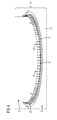
Fig. 4 , all theholes 15 of the flange 13 (and also the holes of the inner flange, which are not shown) come into engagement with the shank 7 of arespective bolt 6. Once thetower 3 has been fully lowered, theflange 13 lies against theconcrete body 11 as seen inFig. 4 . Then, the aligningtools 12 are unscrewed, for example using a socket wrench, from thebolts 6. The aligningtools 12 can be reused hereafter for a further aligning task at another tower installation. Hereafter, nuts (not shown) are screwed onto a shank 7 of eachbolt 6 so as to fixedly connect thefoundation 2 and thetower 3 to each other. - Although the present invention has been described in accordance with preferred embodiments, it is obvious for a person skilled in the art that modifications are possible in all embodiments.
- For example, the aligning
tools 12 may also or instead be attached tobolts 6 of the inner row 4 (seeFig. 1 ). Further, the aligningtools 12 may be used in connection with other fasteners, for example pins, which do not have an outer thread. In this case, thereceptacle 17 of each aligningtool 12 may be formed without theinner thread 21.
Claims (15)
- An aligning tool (12) in the field of wind turbines (1) for aligning a hole (15) with a fastener (6) for insertion of the fastener (6) into the hole (15), the aligning tool (12) comprising:a first section (16) adapted for connecting to the fastener (6) anda second section (22) having an outside diameter (24, 25) tapering down in a direction away from the first section (16).
- The aligning tool according to claim 1, wherein the first section (16) comprises a receptacle (17) to receive the fastener (6).
- The aligning tool according to claim 1 or claim 2, wherein the first section (16) comprises an inner thread (21) adapted to be screwed onto the fastener (6).
- The aligning tool according to claim 3, comprising a geometry (27) adapted to apply a torque for screwing the first section (16) onto the fastener (6).
- The aligning tool according to claim 4, wherein the geometry (27) is adapted to come into engagement with a wrench or screwdriver.
- The aligning tool according to claim 5, wherein the geometry (27) is formed as a hexagon head.
- The aligning tool according to claim 6, wherein the hexagon head (27) adjoins an end (31) of the second section (22) pointing away from the first section (16).
- The aligning tool according to one of claims 1 to 7, wherein the first and second section (16, 22) comprise an outer rocket-shaped surface (26).
- A set (10) in the field of wind turbines (1), comprising:a first part (2) comprising at least one fastener (6),a second part (3) comprising at least one hole (15) andan aligning tool (12) according to one of claims 1 to 8, the aligning tool (12) being adapted to align the at least one hole (15) and the at least one fastener (6) for insertion of the at least one fastener (6) into the at least one hole (15).
- The set according to claim 9, wherein the second section (22) of the aligning tool (12) has a first outside diameter (24) corresponding to the inside diameter of the hole (15) and a second outside diameter (25) smaller than the first outside diameter (24), the second section (22) tapering down from the first and the second diameter (24, 25).
- The set according to claim 9 or claim 10, wherein the first part (2) is a foundation of a wind turbine (1), and the second part (3) is a tower of the wind turbine (1).
- The set according to one of claims 9 to 11, wherein the fastener (6) is a bolt, a screw, a stud or a pin.
- The set according to claim 12, wherein the foundation (2) has at least one row (4, 5) of circularly arranged bolts (6) and the tower (3) has at least one row (14) of circularly arranged holes (15), wherein at least one aligning tool (12) is screwed onto a bolt (6).
- A use of an aligning tool (12) according to one of claims 1 to 8 for aligning a hole (15) and a fastener (6) for insertion of the fastener (6) into the hole (15) in the field of wind turbines (1).
- A method for assembling a wind turbine (1), wherein a hole (15) and a fastener (6) are aligned for insertion of the fastener (6) into the hole (15) using an aligning tool according to one of claims 1 to 8.
Priority Applications (4)
| Application Number | Priority Date | Filing Date | Title |
|---|---|---|---|
| DK12168844.4T DK2667017T3 (en) | 2012-05-22 | 2012-05-22 | Set of a plurality of alignment tools in the field of wind turbines for tower and bottom alignment |
| EP12168844.4A EP2667017B1 (en) | 2012-05-22 | 2012-05-22 | A set of multiple aligning tools in the field of wind turbines for aligning tower and base |
| US13/896,536 US9579757B2 (en) | 2012-05-22 | 2013-05-17 | Aligning tool in the field of wind turbines for aligning a hole with a fastener |
| CN201310191635.XA CN103423278B (en) | 2012-05-22 | 2013-05-22 | Field of wind turbines for alignment tool that hole is alignd with securing member |
Applications Claiming Priority (1)
| Application Number | Priority Date | Filing Date | Title |
|---|---|---|---|
| EP12168844.4A EP2667017B1 (en) | 2012-05-22 | 2012-05-22 | A set of multiple aligning tools in the field of wind turbines for aligning tower and base |
Publications (2)
| Publication Number | Publication Date |
|---|---|
| EP2667017A1 true EP2667017A1 (en) | 2013-11-27 |
| EP2667017B1 EP2667017B1 (en) | 2015-02-25 |
Family
ID=46168180
Family Applications (1)
| Application Number | Title | Priority Date | Filing Date |
|---|---|---|---|
| EP12168844.4A Active EP2667017B1 (en) | 2012-05-22 | 2012-05-22 | A set of multiple aligning tools in the field of wind turbines for aligning tower and base |
Country Status (4)
| Country | Link |
|---|---|
| US (1) | US9579757B2 (en) |
| EP (1) | EP2667017B1 (en) |
| CN (1) | CN103423278B (en) |
| DK (1) | DK2667017T3 (en) |
Cited By (4)
| Publication number | Priority date | Publication date | Assignee | Title |
|---|---|---|---|---|
| EP2927485A1 (en) * | 2014-03-31 | 2015-10-07 | Alstom Renovables España, S.L. | Aligning wind turbine components |
| EP2998569A1 (en) | 2014-09-22 | 2016-03-23 | Siemens Aktiengesellschaft | Arrangement to align a part of a wind turbine |
| EP2998570A1 (en) | 2014-09-22 | 2016-03-23 | Siemens Aktiengesellschaft | Arrangement to align a part of a wind turbine |
| CN109322793A (en) * | 2018-12-03 | 2019-02-12 | 重庆大学 | A kind of full assembled concrete-filled double skin steel tube combination tower and node |
Families Citing this family (3)
| Publication number | Priority date | Publication date | Assignee | Title |
|---|---|---|---|---|
| CA2987405A1 (en) * | 2015-05-29 | 2016-12-08 | Tindall Corporation | Method and apparatus for constructing a concrete tower |
| BE1025747B1 (en) * | 2018-09-13 | 2019-06-27 | GeoSea N.V. | Auxiliary device and method for establishing a bolt connection between connecting flanges of a first and a second construction |
| CN113386079B (en) * | 2020-03-11 | 2022-11-25 | 中国航发商用航空发动机有限责任公司 | Mounting method, tool and fastening kit for special-shaped lock ring |
Citations (6)
| Publication number | Priority date | Publication date | Assignee | Title |
|---|---|---|---|---|
| FR1338898A (en) * | 1962-07-16 | 1963-10-04 | Expl Des Etablissements Boilot | Protective spindle for mounting assembly bolts, especially frames |
| US4005629A (en) * | 1974-04-04 | 1977-02-01 | Franklin James W | Truss bolt drift pin |
| JPH05332334A (en) * | 1992-06-03 | 1993-12-14 | Mutsuo Goto | Anchor bolt protector |
| US20100080667A1 (en) * | 2008-09-26 | 2010-04-01 | Larry Reed | Protective cover for fasteners |
| US20100077696A1 (en) * | 2008-09-29 | 2010-04-01 | Siemens Aktiengesellschaft | Method and Tool for Aligning Wind Turbine Tower Fasteners |
| WO2011109658A2 (en) * | 2010-03-04 | 2011-09-09 | Kop-Flex, Inc. | Fastener for flexible element couplings |
Family Cites Families (16)
| Publication number | Priority date | Publication date | Assignee | Title |
|---|---|---|---|---|
| US4883399A (en) * | 1988-12-05 | 1989-11-28 | Maclean-Fogg Company | Plastic encapsulated nut and washer assembly |
| DE4215635C2 (en) * | 1992-05-12 | 1998-09-03 | Kleinhuis Hermann Gmbh | Plastic screw connection for the insertion and implementation, sealing and strain relief of cables, lines or hoses |
| US5442133A (en) * | 1993-09-08 | 1995-08-15 | Emhart Inc. | Grounding stud/nut |
| US6135509A (en) * | 1999-02-22 | 2000-10-24 | Billington Welding & Manufacturing, Inc. | Safety collar and tendon assembly for threaded connections |
| US7788802B2 (en) * | 2001-01-10 | 2010-09-07 | Newfrey Llc | Method of fastening an electrical contact |
| EP1676675A4 (en) * | 2003-09-24 | 2009-03-04 | Koyokizai Co Ltd | Tool for tightening security nut, tool for releasing security nut, tool for both tightening and releasing security nut, and security nut for exclusive use of these tools |
| US7581913B2 (en) * | 2005-01-25 | 2009-09-01 | Honda Motor Company, Ltd. | Seal nut assembly and method of manufacture |
| JP5332334B2 (en) | 2008-06-19 | 2013-11-06 | 株式会社リコー | Image forming apparatus and image forming system |
| US8245603B2 (en) * | 2008-12-09 | 2012-08-21 | Textron Innovations Inc. | Driver with tapered hex socket |
| ES2388807T3 (en) | 2008-12-16 | 2012-10-18 | Vestas Wind Systems A/S | Foundation to allow the anchoring of a wind turbine tower to it by means of replaceable through bolts |
| US7892049B1 (en) * | 2009-08-18 | 2011-02-22 | GM Global Technology Operations LLC | Electrical connector assemblies |
| US20110138706A1 (en) | 2010-08-13 | 2011-06-16 | Stefan Voss | Wind turbine anchor element |
| GB2483678B (en) | 2010-09-15 | 2013-09-18 | Vestas Wind Sys As | An apparatus for and method of mounting wind turbine blades on a wind turbine tower |
| DE102010047239A1 (en) * | 2010-10-04 | 2012-04-05 | Lumberg Connect Gmbh | Device for tension-relieving fixing of cables |
| ES2396087B1 (en) * | 2011-06-30 | 2014-05-19 | Acciona Windpower, S.A. | ASSEMBLY PROCEDURE OF A MOUNTAINER AND AEROGENERATOR ASSEMBLED ACCORDING TO THIS PROCEDURE |
| US9156147B2 (en) * | 2012-02-15 | 2015-10-13 | Black & Decker Inc. | Quick change bit holder with ring magnet |
-
2012
- 2012-05-22 DK DK12168844.4T patent/DK2667017T3/en active
- 2012-05-22 EP EP12168844.4A patent/EP2667017B1/en active Active
-
2013
- 2013-05-17 US US13/896,536 patent/US9579757B2/en active Active
- 2013-05-22 CN CN201310191635.XA patent/CN103423278B/en active Active
Patent Citations (6)
| Publication number | Priority date | Publication date | Assignee | Title |
|---|---|---|---|---|
| FR1338898A (en) * | 1962-07-16 | 1963-10-04 | Expl Des Etablissements Boilot | Protective spindle for mounting assembly bolts, especially frames |
| US4005629A (en) * | 1974-04-04 | 1977-02-01 | Franklin James W | Truss bolt drift pin |
| JPH05332334A (en) * | 1992-06-03 | 1993-12-14 | Mutsuo Goto | Anchor bolt protector |
| US20100080667A1 (en) * | 2008-09-26 | 2010-04-01 | Larry Reed | Protective cover for fasteners |
| US20100077696A1 (en) * | 2008-09-29 | 2010-04-01 | Siemens Aktiengesellschaft | Method and Tool for Aligning Wind Turbine Tower Fasteners |
| WO2011109658A2 (en) * | 2010-03-04 | 2011-09-09 | Kop-Flex, Inc. | Fastener for flexible element couplings |
Cited By (9)
| Publication number | Priority date | Publication date | Assignee | Title |
|---|---|---|---|---|
| EP2927485A1 (en) * | 2014-03-31 | 2015-10-07 | Alstom Renovables España, S.L. | Aligning wind turbine components |
| WO2015150316A1 (en) * | 2014-03-31 | 2015-10-08 | Alstom Renewable Technologies | Aligning wind turbine components |
| EP2998569A1 (en) | 2014-09-22 | 2016-03-23 | Siemens Aktiengesellschaft | Arrangement to align a part of a wind turbine |
| EP2998570A1 (en) | 2014-09-22 | 2016-03-23 | Siemens Aktiengesellschaft | Arrangement to align a part of a wind turbine |
| CN105443321A (en) * | 2014-09-22 | 2016-03-30 | 西门子公司 | Arrangement to align a part of a wind turbine |
| US9651019B2 (en) | 2014-09-22 | 2017-05-16 | Siemens Aktiengesellschaft | Arrangement to align a part of a wind turbine |
| US9784239B2 (en) | 2014-09-22 | 2017-10-10 | Siemens Aktiengesellschaft | Arrangement to align a part of a wind turbine |
| CN105443321B (en) * | 2014-09-22 | 2019-10-15 | 西门子歌美飒可再生能源公司 | Structure for aligning a part of a wind turbine |
| CN109322793A (en) * | 2018-12-03 | 2019-02-12 | 重庆大学 | A kind of full assembled concrete-filled double skin steel tube combination tower and node |
Also Published As
| Publication number | Publication date |
|---|---|
| DK2667017T3 (en) | 2015-03-09 |
| CN103423278A (en) | 2013-12-04 |
| EP2667017B1 (en) | 2015-02-25 |
| US20130312241A1 (en) | 2013-11-28 |
| CN103423278B (en) | 2017-03-08 |
| US9579757B2 (en) | 2017-02-28 |
Similar Documents
| Publication | Publication Date | Title |
|---|---|---|
| US9579757B2 (en) | Aligning tool in the field of wind turbines for aligning a hole with a fastener | |
| JP5985607B2 (en) | Blind rivet bolt | |
| US10711814B2 (en) | Tapered lead-in for interference fit fasteners | |
| CN111287386B (en) | Mechanical connection device and steel bar connection method for steel bar part commercialized construction | |
| KR20110120832A (en) | Concave-convex shapes on bolts and nuts to minimize bending | |
| EP2522862A1 (en) | Fastening assembly | |
| EP2305908A1 (en) | After application anchor bolt | |
| JP2015036586A (en) | Shaft coupling assembly and method for coupling shafts | |
| US20150104269A1 (en) | Self-Drilling Bolt and Nut Assembly | |
| US8641344B1 (en) | Panel fastener | |
| CN204512120U (en) | Connect bearing pin | |
| US8579567B2 (en) | Device for blind fixation | |
| JP6791943B2 (en) | Fasteners and Fastener Systems for Soft Materials | |
| US20080078083A1 (en) | Drive pin system for a wind turbine structural tower | |
| JP4949180B2 (en) | Fastener | |
| US20130047434A1 (en) | Tool for mounting stud bolts | |
| US20160123368A1 (en) | Fastener for blind hole | |
| US20230175544A1 (en) | Offset attachment device | |
| JP2007298155A (en) | Clamp-connection device, and clamp-connection method | |
| JP2013087946A (en) | Insert nut and mounting method thereof | |
| CN213808408U (en) | Standardized anti-loose bolt and nut assembly for railway large-scale assembly | |
| CN212407269U (en) | High-strength bolt connecting pair for connecting large-scale multilayer structure of wind generating set | |
| US11833648B2 (en) | Functional unit with fastening element and fixing element | |
| CN105952754A (en) | Lock bolt convenient to disassemble | |
| CN114060386A (en) | Standardized anti-loose bolt and nut assembly for railway large-scale assembly |
Legal Events
| Date | Code | Title | Description |
|---|---|---|---|
| PUAI | Public reference made under article 153(3) epc to a published international application that has entered the european phase |
Free format text: ORIGINAL CODE: 0009012 |
|
| AK | Designated contracting states |
Kind code of ref document: A1 Designated state(s): AL AT BE BG CH CY CZ DE DK EE ES FI FR GB GR HR HU IE IS IT LI LT LU LV MC MK MT NL NO PL PT RO RS SE SI SK SM TR |
|
| AX | Request for extension of the european patent |
Extension state: BA ME |
|
| 17P | Request for examination filed |
Effective date: 20140527 |
|
| RBV | Designated contracting states (corrected) |
Designated state(s): AL AT BE BG CH CY CZ DE DK EE ES FI FR GB GR HR HU IE IS IT LI LT LU LV MC MK MT NL NO PL PT RO RS SE SI SK SM TR |
|
| GRAP | Despatch of communication of intention to grant a patent |
Free format text: ORIGINAL CODE: EPIDOSNIGR1 |
|
| RIC1 | Information provided on ipc code assigned before grant |
Ipc: F03D 11/04 20060101ALI20140818BHEP Ipc: F03D 1/00 20060101AFI20140818BHEP Ipc: E02D 27/42 20060101ALI20140818BHEP Ipc: F16B 37/14 20060101ALI20140818BHEP Ipc: E04H 1/00 20060101ALI20140818BHEP |
|
| INTG | Intention to grant announced |
Effective date: 20140916 |
|
| GRAS | Grant fee paid |
Free format text: ORIGINAL CODE: EPIDOSNIGR3 |
|
| GRAA | (expected) grant |
Free format text: ORIGINAL CODE: 0009210 |
|
| AK | Designated contracting states |
Kind code of ref document: B1 Designated state(s): AL AT BE BG CH CY CZ DE DK EE ES FI FR GB GR HR HU IE IS IT LI LT LU LV MC MK MT NL NO PL PT RO RS SE SI SK SM TR |
|
| REG | Reference to a national code |
Ref country code: GB Ref legal event code: FG4D |
|
| REG | Reference to a national code |
Ref country code: CH Ref legal event code: EP |
|
| REG | Reference to a national code |
Ref country code: DK Ref legal event code: T3 Effective date: 20150305 |
|
| REG | Reference to a national code |
Ref country code: IE Ref legal event code: FG4D |
|
| REG | Reference to a national code |
Ref country code: DE Ref legal event code: R096 Ref document number: 602012005372 Country of ref document: DE Effective date: 20150409 |
|
| REG | Reference to a national code |
Ref country code: AT Ref legal event code: REF Ref document number: 712226 Country of ref document: AT Kind code of ref document: T Effective date: 20150415 |
|
| REG | Reference to a national code |
Ref country code: NL Ref legal event code: VDEP Effective date: 20150225 |
|
| REG | Reference to a national code |
Ref country code: AT Ref legal event code: MK05 Ref document number: 712226 Country of ref document: AT Kind code of ref document: T Effective date: 20150225 |
|
| REG | Reference to a national code |
Ref country code: LT Ref legal event code: MG4D |
|
| PG25 | Lapsed in a contracting state [announced via postgrant information from national office to epo] |
Ref country code: NO Free format text: LAPSE BECAUSE OF FAILURE TO SUBMIT A TRANSLATION OF THE DESCRIPTION OR TO PAY THE FEE WITHIN THE PRESCRIBED TIME-LIMIT Effective date: 20150525 Ref country code: ES Free format text: LAPSE BECAUSE OF FAILURE TO SUBMIT A TRANSLATION OF THE DESCRIPTION OR TO PAY THE FEE WITHIN THE PRESCRIBED TIME-LIMIT Effective date: 20150225 Ref country code: LT Free format text: LAPSE BECAUSE OF FAILURE TO SUBMIT A TRANSLATION OF THE DESCRIPTION OR TO PAY THE FEE WITHIN THE PRESCRIBED TIME-LIMIT Effective date: 20150225 Ref country code: SE Free format text: LAPSE BECAUSE OF FAILURE TO SUBMIT A TRANSLATION OF THE DESCRIPTION OR TO PAY THE FEE WITHIN THE PRESCRIBED TIME-LIMIT Effective date: 20150225 Ref country code: HR Free format text: LAPSE BECAUSE OF FAILURE TO SUBMIT A TRANSLATION OF THE DESCRIPTION OR TO PAY THE FEE WITHIN THE PRESCRIBED TIME-LIMIT Effective date: 20150225 Ref country code: FI Free format text: LAPSE BECAUSE OF FAILURE TO SUBMIT A TRANSLATION OF THE DESCRIPTION OR TO PAY THE FEE WITHIN THE PRESCRIBED TIME-LIMIT Effective date: 20150225 |
|
| PG25 | Lapsed in a contracting state [announced via postgrant information from national office to epo] |
Ref country code: GR Free format text: LAPSE BECAUSE OF FAILURE TO SUBMIT A TRANSLATION OF THE DESCRIPTION OR TO PAY THE FEE WITHIN THE PRESCRIBED TIME-LIMIT Effective date: 20150526 Ref country code: IS Free format text: LAPSE BECAUSE OF FAILURE TO SUBMIT A TRANSLATION OF THE DESCRIPTION OR TO PAY THE FEE WITHIN THE PRESCRIBED TIME-LIMIT Effective date: 20150625 Ref country code: AT Free format text: LAPSE BECAUSE OF FAILURE TO SUBMIT A TRANSLATION OF THE DESCRIPTION OR TO PAY THE FEE WITHIN THE PRESCRIBED TIME-LIMIT Effective date: 20150225 Ref country code: LV Free format text: LAPSE BECAUSE OF FAILURE TO SUBMIT A TRANSLATION OF THE DESCRIPTION OR TO PAY THE FEE WITHIN THE PRESCRIBED TIME-LIMIT Effective date: 20150225 Ref country code: RS Free format text: LAPSE BECAUSE OF FAILURE TO SUBMIT A TRANSLATION OF THE DESCRIPTION OR TO PAY THE FEE WITHIN THE PRESCRIBED TIME-LIMIT Effective date: 20150225 |
|
| PG25 | Lapsed in a contracting state [announced via postgrant information from national office to epo] |
Ref country code: NL Free format text: LAPSE BECAUSE OF FAILURE TO SUBMIT A TRANSLATION OF THE DESCRIPTION OR TO PAY THE FEE WITHIN THE PRESCRIBED TIME-LIMIT Effective date: 20150225 |
|
| PG25 | Lapsed in a contracting state [announced via postgrant information from national office to epo] |
Ref country code: RO Free format text: LAPSE BECAUSE OF FAILURE TO SUBMIT A TRANSLATION OF THE DESCRIPTION OR TO PAY THE FEE WITHIN THE PRESCRIBED TIME-LIMIT Effective date: 20150225 Ref country code: CZ Free format text: LAPSE BECAUSE OF FAILURE TO SUBMIT A TRANSLATION OF THE DESCRIPTION OR TO PAY THE FEE WITHIN THE PRESCRIBED TIME-LIMIT Effective date: 20150225 Ref country code: EE Free format text: LAPSE BECAUSE OF FAILURE TO SUBMIT A TRANSLATION OF THE DESCRIPTION OR TO PAY THE FEE WITHIN THE PRESCRIBED TIME-LIMIT Effective date: 20150225 Ref country code: SK Free format text: LAPSE BECAUSE OF FAILURE TO SUBMIT A TRANSLATION OF THE DESCRIPTION OR TO PAY THE FEE WITHIN THE PRESCRIBED TIME-LIMIT Effective date: 20150225 |
|
| REG | Reference to a national code |
Ref country code: DE Ref legal event code: R097 Ref document number: 602012005372 Country of ref document: DE |
|
| PG25 | Lapsed in a contracting state [announced via postgrant information from national office to epo] |
Ref country code: PL Free format text: LAPSE BECAUSE OF FAILURE TO SUBMIT A TRANSLATION OF THE DESCRIPTION OR TO PAY THE FEE WITHIN THE PRESCRIBED TIME-LIMIT Effective date: 20150225 |
|
| PG25 | Lapsed in a contracting state [announced via postgrant information from national office to epo] |
Ref country code: IT Free format text: LAPSE BECAUSE OF FAILURE TO SUBMIT A TRANSLATION OF THE DESCRIPTION OR TO PAY THE FEE WITHIN THE PRESCRIBED TIME-LIMIT Effective date: 20150225 |
|
| REG | Reference to a national code |
Ref country code: CH Ref legal event code: PL |
|
| PLBE | No opposition filed within time limit |
Free format text: ORIGINAL CODE: 0009261 |
|
| STAA | Information on the status of an ep patent application or granted ep patent |
Free format text: STATUS: NO OPPOSITION FILED WITHIN TIME LIMIT |
|
| PG25 | Lapsed in a contracting state [announced via postgrant information from national office to epo] |
Ref country code: CH Free format text: LAPSE BECAUSE OF NON-PAYMENT OF DUE FEES Effective date: 20150531 Ref country code: LU Free format text: LAPSE BECAUSE OF FAILURE TO SUBMIT A TRANSLATION OF THE DESCRIPTION OR TO PAY THE FEE WITHIN THE PRESCRIBED TIME-LIMIT Effective date: 20150522 Ref country code: LI Free format text: LAPSE BECAUSE OF NON-PAYMENT OF DUE FEES Effective date: 20150531 Ref country code: MC Free format text: LAPSE BECAUSE OF FAILURE TO SUBMIT A TRANSLATION OF THE DESCRIPTION OR TO PAY THE FEE WITHIN THE PRESCRIBED TIME-LIMIT Effective date: 20150225 |
|
| 26N | No opposition filed |
Effective date: 20151126 |
|
| REG | Reference to a national code |
Ref country code: IE Ref legal event code: MM4A |
|
| REG | Reference to a national code |
Ref country code: FR Ref legal event code: ST Effective date: 20160129 |
|
| PG25 | Lapsed in a contracting state [announced via postgrant information from national office to epo] |
Ref country code: SI Free format text: LAPSE BECAUSE OF FAILURE TO SUBMIT A TRANSLATION OF THE DESCRIPTION OR TO PAY THE FEE WITHIN THE PRESCRIBED TIME-LIMIT Effective date: 20150225 |
|
| PG25 | Lapsed in a contracting state [announced via postgrant information from national office to epo] |
Ref country code: IE Free format text: LAPSE BECAUSE OF NON-PAYMENT OF DUE FEES Effective date: 20150522 |
|
| PG25 | Lapsed in a contracting state [announced via postgrant information from national office to epo] |
Ref country code: FR Free format text: LAPSE BECAUSE OF NON-PAYMENT OF DUE FEES Effective date: 20150601 Ref country code: BE Free format text: LAPSE BECAUSE OF FAILURE TO SUBMIT A TRANSLATION OF THE DESCRIPTION OR TO PAY THE FEE WITHIN THE PRESCRIBED TIME-LIMIT Effective date: 20150225 |
|
| PG25 | Lapsed in a contracting state [announced via postgrant information from national office to epo] |
Ref country code: MT Free format text: LAPSE BECAUSE OF FAILURE TO SUBMIT A TRANSLATION OF THE DESCRIPTION OR TO PAY THE FEE WITHIN THE PRESCRIBED TIME-LIMIT Effective date: 20150225 |
|
| PG25 | Lapsed in a contracting state [announced via postgrant information from national office to epo] |
Ref country code: HU Free format text: LAPSE BECAUSE OF FAILURE TO SUBMIT A TRANSLATION OF THE DESCRIPTION OR TO PAY THE FEE WITHIN THE PRESCRIBED TIME-LIMIT; INVALID AB INITIO Effective date: 20120522 Ref country code: SM Free format text: LAPSE BECAUSE OF FAILURE TO SUBMIT A TRANSLATION OF THE DESCRIPTION OR TO PAY THE FEE WITHIN THE PRESCRIBED TIME-LIMIT Effective date: 20150225 Ref country code: BG Free format text: LAPSE BECAUSE OF FAILURE TO SUBMIT A TRANSLATION OF THE DESCRIPTION OR TO PAY THE FEE WITHIN THE PRESCRIBED TIME-LIMIT Effective date: 20150225 |
|
| PG25 | Lapsed in a contracting state [announced via postgrant information from national office to epo] |
Ref country code: CY Free format text: LAPSE BECAUSE OF FAILURE TO SUBMIT A TRANSLATION OF THE DESCRIPTION OR TO PAY THE FEE WITHIN THE PRESCRIBED TIME-LIMIT Effective date: 20150225 |
|
| PG25 | Lapsed in a contracting state [announced via postgrant information from national office to epo] |
Ref country code: TR Free format text: LAPSE BECAUSE OF FAILURE TO SUBMIT A TRANSLATION OF THE DESCRIPTION OR TO PAY THE FEE WITHIN THE PRESCRIBED TIME-LIMIT Effective date: 20150225 |
|
| PG25 | Lapsed in a contracting state [announced via postgrant information from national office to epo] |
Ref country code: MK Free format text: LAPSE BECAUSE OF FAILURE TO SUBMIT A TRANSLATION OF THE DESCRIPTION OR TO PAY THE FEE WITHIN THE PRESCRIBED TIME-LIMIT Effective date: 20150225 Ref country code: PT Free format text: LAPSE BECAUSE OF FAILURE TO SUBMIT A TRANSLATION OF THE DESCRIPTION OR TO PAY THE FEE WITHIN THE PRESCRIBED TIME-LIMIT Effective date: 20150225 |
|
| PG25 | Lapsed in a contracting state [announced via postgrant information from national office to epo] |
Ref country code: AL Free format text: LAPSE BECAUSE OF FAILURE TO SUBMIT A TRANSLATION OF THE DESCRIPTION OR TO PAY THE FEE WITHIN THE PRESCRIBED TIME-LIMIT Effective date: 20150225 |
|
| REG | Reference to a national code |
Ref country code: DE Ref legal event code: R081 Ref document number: 602012005372 Country of ref document: DE Owner name: SIEMENS GAMESA RENEWABLE ENERGY A/S, DK Free format text: FORMER OWNER: SIEMENS AKTIENGESELLSCHAFT, 80333 MUENCHEN, DE |
|
| REG | Reference to a national code |
Ref country code: GB Ref legal event code: 732E Free format text: REGISTERED BETWEEN 20191128 AND 20191204 |
|
| PGFP | Annual fee paid to national office [announced via postgrant information from national office to epo] |
Ref country code: DK Payment date: 20230522 Year of fee payment: 12 Ref country code: DE Payment date: 20230519 Year of fee payment: 12 |
|
| PGFP | Annual fee paid to national office [announced via postgrant information from national office to epo] |
Ref country code: GB Payment date: 20230522 Year of fee payment: 12 |