EP2666979A2 - Valve timing control apparatus - Google Patents
Valve timing control apparatus Download PDFInfo
- Publication number
- EP2666979A2 EP2666979A2 EP13168589.3A EP13168589A EP2666979A2 EP 2666979 A2 EP2666979 A2 EP 2666979A2 EP 13168589 A EP13168589 A EP 13168589A EP 2666979 A2 EP2666979 A2 EP 2666979A2
- Authority
- EP
- European Patent Office
- Prior art keywords
- communication
- lock
- fluid passage
- fluid
- rotation member
- Prior art date
- Legal status (The legal status is an assumption and is not a legal conclusion. Google has not performed a legal analysis and makes no representation as to the accuracy of the status listed.)
- Granted
Links
Images


Classifications
-
- F—MECHANICAL ENGINEERING; LIGHTING; HEATING; WEAPONS; BLASTING
- F01—MACHINES OR ENGINES IN GENERAL; ENGINE PLANTS IN GENERAL; STEAM ENGINES
- F01L—CYCLICALLY OPERATING VALVES FOR MACHINES OR ENGINES
- F01L1/00—Valve-gear or valve arrangements, e.g. lift-valve gear
- F01L1/34—Valve-gear or valve arrangements, e.g. lift-valve gear characterised by the provision of means for changing the timing of the valves without changing the duration of opening and without affecting the magnitude of the valve lift
- F01L1/344—Valve-gear or valve arrangements, e.g. lift-valve gear characterised by the provision of means for changing the timing of the valves without changing the duration of opening and without affecting the magnitude of the valve lift changing the angular relationship between crankshaft and camshaft, e.g. using helicoidal gear
- F01L1/3442—Valve-gear or valve arrangements, e.g. lift-valve gear characterised by the provision of means for changing the timing of the valves without changing the duration of opening and without affecting the magnitude of the valve lift changing the angular relationship between crankshaft and camshaft, e.g. using helicoidal gear using hydraulic chambers with variable volume to transmit the rotating force
- F01L2001/34423—Details relating to the hydraulic feeding circuit
-
- F—MECHANICAL ENGINEERING; LIGHTING; HEATING; WEAPONS; BLASTING
- F01—MACHINES OR ENGINES IN GENERAL; ENGINE PLANTS IN GENERAL; STEAM ENGINES
- F01L—CYCLICALLY OPERATING VALVES FOR MACHINES OR ENGINES
- F01L1/00—Valve-gear or valve arrangements, e.g. lift-valve gear
- F01L1/34—Valve-gear or valve arrangements, e.g. lift-valve gear characterised by the provision of means for changing the timing of the valves without changing the duration of opening and without affecting the magnitude of the valve lift
- F01L1/344—Valve-gear or valve arrangements, e.g. lift-valve gear characterised by the provision of means for changing the timing of the valves without changing the duration of opening and without affecting the magnitude of the valve lift changing the angular relationship between crankshaft and camshaft, e.g. using helicoidal gear
- F01L1/3442—Valve-gear or valve arrangements, e.g. lift-valve gear characterised by the provision of means for changing the timing of the valves without changing the duration of opening and without affecting the magnitude of the valve lift changing the angular relationship between crankshaft and camshaft, e.g. using helicoidal gear using hydraulic chambers with variable volume to transmit the rotating force
- F01L2001/3445—Details relating to the hydraulic means for changing the angular relationship
- F01L2001/34453—Locking means between driving and driven members
- F01L2001/34466—Locking means between driving and driven members with multiple locking devices
-
- F—MECHANICAL ENGINEERING; LIGHTING; HEATING; WEAPONS; BLASTING
- F01—MACHINES OR ENGINES IN GENERAL; ENGINE PLANTS IN GENERAL; STEAM ENGINES
- F01L—CYCLICALLY OPERATING VALVES FOR MACHINES OR ENGINES
- F01L1/00—Valve-gear or valve arrangements, e.g. lift-valve gear
- F01L1/34—Valve-gear or valve arrangements, e.g. lift-valve gear characterised by the provision of means for changing the timing of the valves without changing the duration of opening and without affecting the magnitude of the valve lift
- F01L1/344—Valve-gear or valve arrangements, e.g. lift-valve gear characterised by the provision of means for changing the timing of the valves without changing the duration of opening and without affecting the magnitude of the valve lift changing the angular relationship between crankshaft and camshaft, e.g. using helicoidal gear
- F01L1/3442—Valve-gear or valve arrangements, e.g. lift-valve gear characterised by the provision of means for changing the timing of the valves without changing the duration of opening and without affecting the magnitude of the valve lift changing the angular relationship between crankshaft and camshaft, e.g. using helicoidal gear using hydraulic chambers with variable volume to transmit the rotating force
- F01L2001/3445—Details relating to the hydraulic means for changing the angular relationship
- F01L2001/34453—Locking means between driving and driven members
- F01L2001/34473—Lock movement perpendicular to camshaft axis
-
- F—MECHANICAL ENGINEERING; LIGHTING; HEATING; WEAPONS; BLASTING
- F01—MACHINES OR ENGINES IN GENERAL; ENGINE PLANTS IN GENERAL; STEAM ENGINES
- F01L—CYCLICALLY OPERATING VALVES FOR MACHINES OR ENGINES
- F01L1/00—Valve-gear or valve arrangements, e.g. lift-valve gear
- F01L1/34—Valve-gear or valve arrangements, e.g. lift-valve gear characterised by the provision of means for changing the timing of the valves without changing the duration of opening and without affecting the magnitude of the valve lift
- F01L1/344—Valve-gear or valve arrangements, e.g. lift-valve gear characterised by the provision of means for changing the timing of the valves without changing the duration of opening and without affecting the magnitude of the valve lift changing the angular relationship between crankshaft and camshaft, e.g. using helicoidal gear
- F01L1/3442—Valve-gear or valve arrangements, e.g. lift-valve gear characterised by the provision of means for changing the timing of the valves without changing the duration of opening and without affecting the magnitude of the valve lift changing the angular relationship between crankshaft and camshaft, e.g. using helicoidal gear using hydraulic chambers with variable volume to transmit the rotating force
- F01L2001/3445—Details relating to the hydraulic means for changing the angular relationship
- F01L2001/34453—Locking means between driving and driven members
- F01L2001/34476—Restrict range locking means
Definitions
- This disclosure generally relates to a variable valve timing control apparatus.
- a rotational phase of a driven side rotation member relative to a driving side rotation member can be varied towards an advancing angle side by draining a fluid in a retarded angle chamber while incrementing a volume of an advanced angle chamber by a pressurized fluid supplied to an advanced angle fluid passage, and the rotational phase can be varied towards a retarded angle side by draining the fluid in the advanced angle chamber while incrementing a volume of the retarded angle chamber by the pressurized fluid supplied to a retarded angle fluid passage.
- the rotational phase of the driven side rotation member relative to the driving side rotation member can be locked at an intermediate phase between a most retarded angle phase and a most advanced angle phase so that an opening and closing timing of an intake valve or an exhaust valve is assumed to be an optimum timing for starting an engine.
- JP2010-223172A discloses a known variable valve timing control apparatus in which three fluid passages each supplying a pressurized fluid to an advanced angle fluid passage, a retarded angle fluid passage, and a lock fluid passage provided at a driven side rotation member are open to a fixed peripheral surface of a fixed member sliding relative to a rotational peripheral surface of the driven side rotation member.
- the pressurized fluid supplied from the fluid passages leaks via a sliding surface between the rotational peripheral surface and the fixed peripheral surface, there is a possibility that a switching operation of a lock member and a change in a valve opening-closing timing cannot be performed at an appropriate timing. Accordingly, it is necessary to machine process the rotational peripheral surface and the fixed peripheral surface with high precision so as not to cause leakages of the fluid via the sliding surface, which is likely to increase manufacturing costs.
- JP3986331 B discloses a known variable valve timing control apparatus which includes an advanced angle fluid passage and a retarded angle fluid passage provided at a driven side rotation member and two fluid passages each supplying a pressurized fluid to the advanced angle fluid passage and the retarded angle fluid passage.
- the advanced angle fluid passage and the retarded angle fluid passage are in communication with two fluid passages each supplying the pressurized fluid to the advanced angle fluid passage and the retarded angle fluid passage, respectively, via a communication portion for retarded angle and a communication portion for advanced angle, respectively, which are formed annularly by dividing a void between the rotational peripheral surface of the driven side rotation member and the fixed peripheral surface of the fixed member by means of seal rings.
- the communication portion for lock is positioned between the communication portion for advanced angle and the communication portion for retarded angle
- the sealing dividing, or defining the communication portion for lock and the communication portion for advanced angle, and the seal ring dividing, or defining the communication portion for lock and the communication portion for retarded angle may be deformed and damaged.
- the seal ring when the pressurized fluid is supplied to the advanced angle fluid passage or the retarded angle fluid passage in a state where the pressurized fluid is not supplied to the lock fluid passage, the seal ring is urged to displace towards the communication portion for lock by a fluid pressure in the communication portion for advanced angle or in the communication portion for retarded angle. Further, when the pressurized fluid is supplied to the lock fluid passage in a state where the pressurized fluid is not supplied to the advanced angle fluid passage and the retarded angle fluid passage, the seal ring is urged to displace towards the communication portion for advanced angle or the communication portion for retarded angle by the fluid pressure in the communication portion for lock.
- the displacement of the seal ring is assumed to be uneven in the circumferential direction, and may be increased within a particular range in the circumferential direction. Because the supply of the pressurized fluid to the advanced angle fluid passage or the retarded angle fluid passage and the supply of the pressurized fluid to the lock fluid passage are repeated as necessity arises, the seal ring may eventually be damaged by fatigue because of deformation.
- a variable valve timing control apparatus includes a driving side rotation member synchronously rotating with a crankshaft of an internal combustion engine, a driven side rotation member positioned to be coaxially rotatable relative to the driving side rotation member about a common rotational axis, synchronously rotating with a camshaft for opening and closing a valve of the internal combustion engine, and including a rotation peripheral surface, a fluid pressure chamber formed between the driving side rotation member and the driven side rotation member, an advanced angle chamber and a retarded angle chamber formed by dividing the fluid pressure chamber by a dividing portion provided at least one of the driving side rotation member and the driven side rotation member, a phase control portion for controlling a rotational phase of the driven side rotation member relative to the driving side rotation member by supplying a pressurized fluid to the advanced angle chamber or to the retarded angle chamber, an intermediate lock mechanism including a lock fluid passage allowing an inflow of the pressurized fluid and a lock member allowing a switching of a locked state where the rotational phase of
- the seal ring sandwiched between two of the communication portion for advanced angle, the communication portion for retarded angle, and the communication portion for lock in a direction of the rotational axis among the plural seal rings includes a communication passage which establishes constant communication between both sides thereof in association with the direction of the rotational axis when temperature of the pressurized fluid is within a temperature range which allows a control of the rotational phase of the driven side rotation member.
- the advanced angle fluid passage, the retarded angle fluid passage, and the lock fluid passage are in communication with the corresponding fluid passages via the communication portion for advanced angle, the communication portion for retarded angle, and the communication portion for lock formed by annularly defining a void provided between the rotation peripheral surface and the fixed peripheral surface by the corresponding seal rings, respectively.
- the seal ring sandwiched between two of the communication passage for advanced angle, the communication passage for retarded angle, and the communication passage for lock in a direction of the rotational axis among the plural seal rings includes the communication passage which is constantly in communication with opposite sides, or both sides in association with the direction of the rotational axis when the temperature of the pressurized fluid is within the temperature range which allows a control of the rotational phase of the driven side rotation member.
- the pressurized fluid can be relieved from one of the communication portions to the other of the communication portions via the communication passage which constantly establishes the communication between the opposite end sides, or the both sides in the rotational axis direction so that a pressure difference between two communication portions which sandwich the seal ring is reduced.
- variable valve timing control apparatus because the displacement of the seal ring towards the adjoining communication portion via the seal ring can be reduced, fatigue caused because of deformation of the seal ring to which the fluid pressure is applied from both sides (opposite end sides) in the axial direction is unlikely generated.
- each of the seal rings is formed in a C-shape including end surfaces facing each other at a portion in a circumferential direction, and the communication passage is defined by a clearance between the end surfaces.
- the communication passage can be readily provided using the clearance formed between the end surfaces.
- the communication passage corresponds to a recessed groove formed on a portion of the seal ring at an outer side in a radial direction or at an inner side in a radial direction, and opposite side portions of the recessed groove in the direction of the rotational axis are open.
- the communication passage can be provided at the outer peripheral side or the inner peripheral side of the seal ring.
- the communication passage corresponds to a through hole which is formed on the seal ring penetrating through the seal ring to open to the both sides in the direction of the rotational axis.
- the communication passage is provided at the through hole penetrating through the seal ring to open to the opposite end sides, or both sides in the rotational axis direction, a sealing performance of the seal ring relative to the rotation peripheral surface or the fixed peripheral surface is readily ensured.
- a circumferential length of the seal ring at an outer portion in a radial direction is shorter than a circumferential length of the seal ring at an inner portion in a radial direction, and a void corresponding to a difference in the circumferential length corresponds to the communication passage.
- the communication passage can be formed more readily at the outer portion in the radial direction of the seal ring than at the inner portion of the seal ring.
- the communication passage is formed only at the outer portion in a radial direction of the seal ring.
- the communication passage can be formed more readily at the outer portion in the radial direction of the seal ring than at the inner portion of the seal ring.
- Fig. 1 is a cross-sectional view of a variable valve timing control apparatus in a rotational axis direction at a fluid control valve side according to a first embodiment disclosed here;
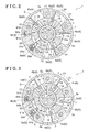
- Fig. 2 is a cross-sectional view taken on line II-II in Fig. 1 ;
- Fig. 3 is a cross-sectional view taken on line III-III in Fig. 1 ;
- Fig. 4 is a cross-sectional view showing a state where a seal ring is attached
- Fig. 5 is a perspective view of the seal ring
- Fig. 6 is a perspective view of a seal ring according to a second embodiment.
- Fig. 7 is a perspective view of a seal ring according to a third embodiment.
- a variable valve timing control apparatus 1 includes an outer rotor 3 and a front plate 4 which serve as a driving side rotation member synchronously rotating with a crankshaft E1 of a vehicle gasoline engine (internal combustion engine) E, and an inner rotor 5 serving as a driven side rotation member.
- the inner rotor 5 is positioned to be coaxially rotatable relative to the outer rotor 3 about a rotational axis X, and synchronously rotates with a camshaft 8 for opening and closing valves for an engine.
- the outer rotor 3 and the inner rotor 5 are formed annularly.
- the inner rotor 5 is integrally mounted to an end portion of the camshaft 8 including a cam for controlling an opening and closing of an intake valve or an exhaust valve of the engine.
- the inner rotor 5 is formed with a recessed portion 14 which includes an inner peripheral surface (i.e., serving as a rotation peripheral surface) 14a formed in a cylindrical configuration to be coaxial to the rotational axis X.
- the inner rotor 5 and the camshaft 8 are integrally fixed by screwing a bolt 13 into a female screw hole 12 formed at a bottom surface of the recessed portion 14.
- the camshaft 8 is rotatably assembled to a cylinder head of the engine.
- the outer rotor 3 is integrally assembled with the front plate 4 to be rotatable relative to the inner rotor 5 within a predetermined angular range.
- a sprocket portion 11 is provided at an outer periphery of the outer rotor 3 coaxially with the outer rotor 3.
- a power transmission member E2 for example, a timing chain or a timing belt is wound around and spanning the sprocket portion 11 and a gear mounted to the crankshaft E1.
- plural protrusion portions 3a protruding inwardly in a radial direction are integrally formed at an inner side of the outer rotor 3 at positions spaced apart from each other in a circumferential direction.
- Four fluid pressure chambers 6 are formed between the outer rotor 3 and the inner rotor 5 and between the protrusion portions 3a which are positioned adjacent to each other in the circumferential direction.
- a groove is formed on the outer peripheral portion of the inner rotor 5 at a portion facing each of the fluid pressure chambers 6, and a vane 7 serving as a dividing portion is provided in each of the grooves.
- the fluid pressure chamber 6 is divided into an advanced angle chamber 6a and a retarded angle chamber 6b positioned in a front-rear arrangement in the circumferential direction (arrowed directions S1, S2 in Figs. 2 and 3 ) by the vane 7.
- the inner rotor 5 is formed with an advanced angle fluid passage 17 for establishing a communication between the recessed portion 14 and the advanced angle chamber 6a, and a retarded angle fluid passage 18 for establishing a communication between the recessed portion 14 and the retarded angle chamber 6b.
- a relative rotational phase of the inner rotor 5 relative to the outer rotor 3 is displaced towards an advanced angle direction S1 or towards a retarded angle direction S2.
- the direction of the advanced angle direction S1 shows a direction indicated with an arrow S1 and the retarded angle direction S2 shows a direction indicated with an arrow S2 shown in Figs. 2 and 3 .
- the operation oil of the retarded angle chamber 6b is drained while incrementing the volume of the advanced angle chamber 6a to displace the relative rotational phase towards the advanced angle direction S1.
- the operation oil in the advanced angle chamber 6a is drained while incrementing the volume of the retarded angle chamber 6b to displace the relative rotational phase towards the retarded angle direction S2.
- An angular range in which the relative rotational phase is displaceable corresponds to a range in which the vane 7 is displaceable inside the fluid pressure chamber 6, and corresponds to an angular range between a most advanced angle phase at which the volume of the retarded angle chamber 6b is maximized and a most advanced angle phase at which the volume of the advanced angle chamber 6a is maximized.
- a fluid control valve mechanism A configures a phase control portion for controlling the relative rotational phase of the inner rotor 5 relative to the outer rotor 3 by supplying the operation oil to the advanced angle chamber 6a or to the retarded angle chamber 6b.
- the fluid control valve mechanism A includes a fluid control valve portion 2. In response to an operation of the fluid control valve portion 2, the supply of the operation oil to the advanced angle chamber 6a or to the retarded angle chamber 6b or the draining of the operation oil from the advanced angle chamber 6a or from the retarded angle chamber 6b is selectively controlled.
- the fluid control valve mechanism A integrally includes a housing 23 provided at the fluid control valve portion 2 and a fixed member 23b formed in a cylindrical shape and coaxially positioned in the recessed portion 14 of the inner rotor 5 to be relatively rotatable.
- the fixed member 23b is formed with a fixed outer peripheral surface 10 coaxially facing the inner peripheral surface 14a of the recessed portion 14 which corresponds to a rotation peripheral surface of the inner rotor 5 in a standstill state.
- the fixed member 23b is fixed to, for example, a front cover of the engine E via the housing 23.
- the fluid control valve portion 2 includes a solenoid 21, a housing 23, and a spool 25.
- the spool 25 is formed in a cylindrical configuration having a bottom, which includes a hollow portion 25a.
- the housing 23 is provided with a first spool housing portion 23a, which includes a hollow portion 24, integrally with the fixed member 23b.
- the spool 25 is housed within the hollow portion 24 of the first spool housing portion 23a to be movable in a spool axial direction which is orthogonal to the rotational axis X of the inner rotor 5.
- a compression spring 26 for biasing the spool 25 towards an opening of the hollow portion 24 is mounted between the spool 25 and a bottom surface of the hollow portion 24.
- the solenoid 21 provided with a rod 22 for reciprocating the spool 25 in an axial direction of the spool 25 is mounted to an end portion of an opening of the first spool housing portion 23a.
- the rod 22 When electrifying the solenoid 21, the rod 22 is moved to protrude to push a bottom portion of the spool 25, and the spool 25 is moved downwardly in Fig. 1 against the biasing force of the compression spring 26.
- the rod 22 When stopping electrifying the solenoid 21, the rod 22 is moved and the spool 25 is moved towards the solenoid 21 by the biasing force of the compression spring 26.
- the solenoid 21, the rod 22, the spool 25, and the compression spring 26 configure the fluid control valve portion 2.
- the advanced angle fluid passage 17, the retarded angle fluid passage 18, and a lock fluid passage 95 described hereinafter are open to the inner peripheral surface 14a of the recessed portion 14.
- the fixed member 23b includes an advanced angle side fluid passage 42, a retarded angle side fluid passage 43, and a passage 99 for lock operation described hereinafter which serve as plural fluid passages (a plurality of fluid passages) for supplying the operation oil to the advanced angle fluid passage 17, the retarded angle fluid passage 18, and the lock fluid passage 95, respectively.
- the advanced angle side fluid passage 42, the retarded angle side fluid passage 43, and the passage 99 for lock operation are open to the fixed outer peripheral surface 10.
- an outer peripheral groove 31 for advanced angle, an outer peripheral groove 32 for retarded angle, and an outer peripheral groove 96 for lock operation each of which are formed in an annular shape are formed on the fixed outer peripheral surface 10 over the entire circumstance to be in parallel to one another, and the outer peripheral groove 96 for lock operation is positioned between the outer peripheral groove 31 for advanced angle and the outer peripheral groove 32 for retarded angle.
- the advanced angle side fluid passage 42 opens to a groove bottom surface of the outer peripheral groove 31 for advanced angle
- the retarded angle side fluid passage 43 opens to a groove bottom surface of the outer peripheral groove 32 for retarded angle
- the passage 99 for lock operation opens to a groove bottom surface of the outer peripheral groove 96.
- Two seal rings 16a, 16b made of resin, or made of rubber and dividing, or defining the adjacent outer peripheral grooves 31, 96, 32, and a seal ring 16c dividing, or defining the outer peripheral groove 32 and an outside of the apparatus are mounted between the inner peripheral surface 14a of the recessed portion 14 and the fixed outer peripheral surface 10.
- Each of the seal rings 16a to 16c is attached to an annular groove 10a formed on the fixed outer peripheral surface 10.
- the advanced angle fluid passage 17, the retarded angle fluid passage 18, and the lock fluid passage 95 which are open to the inner peripheral surface 14a of the recessed portion 14 are in communication with corresponding fluid passages 42, 99, 43, respectively, via a communication portion 19a for advanced angle, a communication portion 19c for retarded angle, and a communication portion 19b for lock positioned between the communication portion 19a for advanced angle side and the communication portion 19c for retarded angle which are divided, or defined by three seal rings 16a to 16c.
- the advanced angle fluid passage 17 is communicated with the advanced angle side fluid passage 42 via the communication portion 19a for advanced angle
- the lock fluid passage 95 is communicated with the fluid passage 99 for lock operation via the communication portion 19b for lock
- the retarded angle fluid passage 18 is communicated with the retarded angle side fluid passage 43 via the communication passage 91c for retarded angle.
- a communication passage 20 formed in a U-shape in cross section is provided at each of the seal ring 16a, which is sandwiched between the communication portion 19a for advanced angle and the communication portion 19b for lock, and the seal ring 16b sandwiched between the communication portion 19b for lock and the communication portion 19c for retarded angle.
- the communication passage 20 is provided at an outer peripheral side and at an inner peripheral side and is constantly in communication with both sides in the rotational axis X direction in a temperature range of the operation oil in which the rotational phase is controllable.
- the seal rings 16a, 16b are positioned between two of the communication portion 19a for advanced angle, the communication portion 19c for retarded angle, and the communication portion 19b for lock in the rotational axis X direction, and the oil pressure affects the seal rings 16a, 16b from the both sides in the rotational axis X direction.
- the seal rings 16a, 16b are formed in a C-shape in a planar view and are formed to have a quadrilateral shape in cross section.
- Each of the seal rings 16a, 16b includes a pair of end surfaces 33 which faces each other to selectively contact each other, that is, to contact each other or separate from each other at a portion in a circumferential direction from a direction orthogonal to the rotational axis X. As shown in Fig.
- each of the end surfaces 33 is formed in a stepwise configuration when viewed from a direction orthogonal to the rotational axis X, where two radial direction end surfaces 33a, 33b arranged along a radial direction of the ring formed at the ring outer peripheral side and the ring inner peripheral side keeping a distance in a ring circumferential direction are connected via a circumferential direction end surface 33c arranged along the ring circumferential direction and formed along an intermediate portion in a ring thickness direction.
- Each of the seal rings 16a, 16b is fitted into the annular groove 10a in a manner that the radial direction end surfaces 33a at the ring inner peripheral side tightly contact each other, the radial direction end surfaces 33b at the ring outer peripheral side are slightly separated from each other in the circumferential direction, and the circumferential direction end surfaces 33c tightly contact each other to provide the communication passage 20 formed by a clearance between the radial direction end surfaces 33b at the ring outer peripheral side.
- a communication passage may be formed by a clearance between the radial direction end surfaces 33a at the ring inner peripheral side by mounting the seal ring 16a, 16b so that the radial direction end surfaces 33a at the ring inner peripheral side are slightly separated from each other in the circumferential direction.
- the operation oil in one of the communication portion 19a for advanced angle, the communication portion 19c for retarded angle, and the communication portion 19b for lock is relieved to the adjoining communication portion via the communication passage 20 to reduce a pressure difference between the communication portion 19a for advanced angle or the communication portion 19c for retarded angle, and the communication portion 19b for lock, and thus the displacement of the seal rings 16a, 16b towards the communication portion 19a for advanced angle and the communication portion 19c for retarded angle, respectively, or towards the communication portion 19b for lock can be reduced.
- the housing 23 is formed with a supply side fluid passage 47 which is in communication with the hollow portion 24 of the first spool housing portion 23a along the direction orthogonal to the spool 25.
- the supply side fluid passage 47 supplies the operation oil from the pump P to the hollow portion 24.
- the advanced angle side fluid passage 42 and the retarded angle side fluid passage 43 are in communication with the hollow portion 24.
- Annular outer peripheral grooves 53a, 53b for draining and an outer peripheral groove 54 for supplying are formed over the entire circumference of the outer peripheral surface of the spool 25.
- the outer peripheral grooves 53a, 53b for draining are in communication with the hollow portion 25a of the spool 25 via through holes 55a, 55b, respectively.
- the outer peripheral groove 54 for supplying is in communication with the supply side fluid passage 47 and the advanced angle side fluid passage 42, and the outer peripheral groove 53b for draining is in communication with the retarded angle side fluid passage 43.
- the outer peripheral groove 54 for supplying is in communication with the supply side fluid passage 47 and the retarded angle side fluid passage 43 and the outer peripheral groove 53a for draining is in communication with the advanced angle side fluid passage 42.
- lock members 92a, 92b which are configured to switch a locked state where the relative rotational phase of the inner rotor 5 relative to the outer rotor 3 are locked at an intermediate phase (see Fig. 3 ) between the most retarded angle phase and the most advanced angle phase and an unlocked state where the locked state is released, are provided between the outer rotor 3 and the inner rotor 5.
- the lock fluid passage 95 allows an inflow of the operation oil into between the recessed portion 14 of the inner rotor 5 and a recessed portion 93 for locking.
- the lock members 92a, 92b are switched to the locked state and to the unlocked state in accordance with a level of the fluid pressure of the operation oil introduced via the lock fluid passage 95.
- An intermediate lock mechanism 9 includes a lock housing portion 91 a, 91 b, a lock member 92a, 92b, the recessed portion 93 for locking which is in communication with the lock fluid passage 95, and a spring 94a, 94b.
- the lock housing portions 91 a, 91 b are formed on the outer rotor 3.
- the lock fluid passage 95 and the recessed portion 93 for locking are formed on the inner rotor 5.
- the lock member 92a, 92b is displaceable between the locked state where the lock member 92a, 92b moves into the recessed portion 93 for locking to lock the rotation of the inner rotor 5 relative to the outer rotor 3 and the unlocked state where the lock member 92a, 92b moves into the lock housing portion 91 a, 91 b from the recessed portion 93 for locking.
- the lock member 92a, 92b is normally biased to protrude towards the recessed portion 93 for locking by the spring 94a, 94b provided at the lock housing portion 91 a, 91 b.
- the operation oil is sent to each of the advanced angle chambers 6a with pressure from the supply side fluid passage 47 via the outer peripheral groove 54 for supplying, the advanced angle side fluid passage 42, the communication portion 19a for advanced angle, and the advanced angle fluid passage 17.
- the vane 7 relatively moves in the advanced angle direction S1 and the operation oil in each of the retarded angle chambers 6b is drained.
- the operation oil is drained to the outside from each of the retarded angle chambers 6b via each of the retarded angle fluid passages 18, the communication portion 19c for retarded angle, the retarded angle side fluid passage 43, the outer peripheral groove 53a for draining, the through hole 55a, and a draining passage.
- the solenoid 21 of the fluid control valve portion 2 is electrified.
- the spool 25 is pushed to move downwardly by the rod 22 of the solenoid 21.
- the operation oil is sent to the retarded angle chamber 6b with pressure from the pump P via the supply side fluid passage 47, the outer peripheral groove 54 for supplying, the retarded angle side fluid passage 43, the communication portion 19c for retarded angle, and the retarded angle fluid passage 18.
- the vane 7 relatively moves in the retarded angle direction S2 to drain the operation fluid in each of the advanced angle chambers 6a.
- the operation fluid is drained to the outside from each of the advanced angle chambers 6a via the advanced angle fluid passage 17, the communication portion 19a for advanced angle, the advanced angle side fluid passage 42, the outer peripheral groove 53b for draining, the through hole 55b, and a draining fluid passage.
- the intermediate lock mechanism 9 is switched to the locked state where the lock member 92a, 92b enters the recessed portion 93 for lock to lock the relative rotational phase of the inner rotor 5 relative to the outer rotor 3 at the intermediate phase.
- the operation oil is supplied to the fluid passage 99 for lock operation from an accumulator, the lock member 92a, 92b retracts from the recessed portion 93 for locking to the lock housing portion 91 a, 91 b, so that the intermediate lock mechanism 9 is switched to the unlocked state.
- variable valve timing control apparatus is particularly effective for an engine having a large fluctuation torque of a cam, for example, a three-cylinder engine or a V-type six cylinder engine.
- FIG. 6 shows seal rings 116a, 116b according to another embodiment of the present invention.
- Each of the seal rings 116a, 116b is formed in a C-shape having a gap 34 formed in a slanting direction relative to the rotational axis X and formed on a portion in the circumferential direction.
- a communication passage 120 which is provided at each of annular seal rings 116a, 116b which define the both sides of the communication portion 19b for lock, a recessed groove formed in a quadrilateral shape in cross section which opens to the both sides in the direction of rotational axis X at a position separated from the gap 34 in the circumferential direction is formed at an outer peripheral side.
- Two communication passages 120 are provided as a series. Other constructions are similar to the first embodiment.
- FIG. 7 shows seal rings 216a, 216b according to another embodiment of the present invention.
- Each of the seal rings 216a, 216b is formed in a C-shape having the gap 34 formed in a slanting direction relative to the rotational axis X and formed on a portion in the circumferential direction.
- a communication passage 220 which is provided at each of annular the seal rings 216a, 216b, a circular through hole which penetrates through the seal ring 16a, 16b to open to the both sides in the direction of rotational axis X is formed at a position separated from the gap 34 in the circumferential direction.
- Two communication passages 220 are provided as a series at a communication portion for lock side. Other constructions are similar to the first embodiment.
- the communication passage 20 which is formed in a recessed and protruding configuration on a surface may be provided at the seal ring 16a, 16b.
- the seal ring 16a, 16b may be formed in a C-shape in cross section including end surfaces 33 which face in a labyrinth manner (i.e., the end surfaces 33 face alternately) each other at a portion in a circumferential direction, and the communication passage 20 may be formed with clearances formed by the end surfaces 33 facing each other in the labyrinth manner (i.e., the end surfaces 33 face alternately).
- a recessed groove which opens to the both side in the direction of the rotational axis X may be formed at the outer peripheral side and at the inner peripheral side of the seal ring 16a, 16b, or may be formed at one of the outer peripheral side and the inner peripheral side of the seal ring 16a, 16b.
- plural recessed grooves which open to the both sides in the rotational axis X direction may be formed with a distance from each other in the circumferential direction of the seal ring.
- variable valve timing control apparatus of the present invention as the communication passage 20 provided at the seal ring 16a, 16b, plural through holes penetrating through the seal ring 16a, 16b to open to the both sides in the rotational axis X direction may be formed with a distance from each other in the circumferential direction of the ring.
- a recessed groove or a through hole serving as the communication passage 20 may be formed on the annular seal rings 16a, 16b which are arranged to continue as a series in the circumferential direction.
- a communication passage which is constantly in communication with the both sides in the rotational axis direction may be formed at the seal ring which is positioned between the communication portion for advanced angle and the communication portion for retarded angle when the temperature of the pressurized fluid is within the temperature region which allows a control of the rotational phase.
- the driven side rotation member may include the advanced angle fluid passage, the retarded angle fluid passage, and the lock fluid passage which open to the rotational outer peripheral surface of the driven side rotation member, and the fixed member which is formed with the fixed inner peripheral surface coaxially facing the rotational outer peripheral surface of the driven side rotation member in a standstill state may include plural fluid passages which separately supply the pressurized fluid to the advanced angle fluid passage, the retarded angle fluid passage, and the lock fluid which open to the fixed inner peripheral surface.
- the present invention is applicable to a variable valve timing control apparatus for various internal combustion engines such as a gasoline engine, diesel engine, or the like, other than an automobile.
Abstract
Description
- This disclosure generally relates to a variable valve timing control apparatus.
- According to a known variable valve timing control apparatus, a rotational phase of a driven side rotation member relative to a driving side rotation member can be varied towards an advancing angle side by draining a fluid in a retarded angle chamber while incrementing a volume of an advanced angle chamber by a pressurized fluid supplied to an advanced angle fluid passage, and the rotational phase can be varied towards a retarded angle side by draining the fluid in the advanced angle chamber while incrementing a volume of the retarded angle chamber by the pressurized fluid supplied to a retarded angle fluid passage. Further, for example, the rotational phase of the driven side rotation member relative to the driving side rotation member can be locked at an intermediate phase between a most retarded angle phase and a most advanced angle phase so that an opening and closing timing of an intake valve or an exhaust valve is assumed to be an optimum timing for starting an engine.
-
JP2010-223172A -
JP3986331 B - Here, it is considered to establish a communication between each of the advanced angle fluid passage, the retarded angle fluid passage, and the lock fluid passage and each of three fluid passages for supplying the pressurized fluid to the advanced angle fluid passage, the retarded angle fluid passage, and the lock fluid passage, respectively, via a communication passage for advanced angle, a communication passage for retarded angle, and a communication passage for lock which are formed by annularly dividing a void provided between a rotational peripheral surface and a fixed peripheral surface by means of seal rings for the variable valve timing control apparatus disclosed in
JP2010-223172A - However, for example, provided that the communication portion for lock is positioned between the communication portion for advanced angle and the communication portion for retarded angle, the sealing dividing, or defining the communication portion for lock and the communication portion for advanced angle, and the seal ring dividing, or defining the communication portion for lock and the communication portion for retarded angle may be deformed and damaged.
- That is, when the pressurized fluid is supplied to the advanced angle fluid passage or the retarded angle fluid passage in a state where the pressurized fluid is not supplied to the lock fluid passage, the seal ring is urged to displace towards the communication portion for lock by a fluid pressure in the communication portion for advanced angle or in the communication portion for retarded angle. Further, when the pressurized fluid is supplied to the lock fluid passage in a state where the pressurized fluid is not supplied to the advanced angle fluid passage and the retarded angle fluid passage, the seal ring is urged to displace towards the communication portion for advanced angle or the communication portion for retarded angle by the fluid pressure in the communication portion for lock. Still further, even when the pressurized fluid is simultaneously supplied to the advanced angle fluid passage or the retarded angle fluid passage, and to the lock fluid passage by a common fluid pump, there is a case that fluid pressure level between the communication portion for advanced angle or the communication portion for the retarded angle and the communication portion for lock slightly differ from each another due to differences in pressure loss, and the seal ring is urged to displace towards the communication portion for advanced angle or the communication portion for retarded angle, or towards the communication portion for lock in response to the pressure difference therebetween.
- Because flexural rigidity of the seal ring in a rotational axis direction is not necessarily even because of slight dispersion of machining precision and an accuracy of dimension along a circumferential direction of the seal ring, the displacement of the seal ring is assumed to be uneven in the circumferential direction, and may be increased within a particular range in the circumferential direction. Because the supply of the pressurized fluid to the advanced angle fluid passage or the retarded angle fluid passage and the supply of the pressurized fluid to the lock fluid passage are repeated as necessity arises, the seal ring may eventually be damaged by fatigue because of deformation.
- A need thus exists for a variable valve timing control apparatus, in which a fatigue because of deformation of a seal ring which is positioned between two of a communication portion for advanced angle, a communication portion for retarded angle, and a communication portion for lock among seal rings unlikely occurs in a construction that an advanced angle fluid passage, a retarded angle fluid passage, and a lock fluid passage are communicated with three fluid passages for separately supplying a pressurized fluid to the advanced angle fluid passage, the retarded angle fluid passage, and the lock fluid passage, respectively, via the communication portion for advanced angle, the communication portion for retarded angle, and the communication portion for lock, respectively, formed by annularly dividing a void provided between a rotational peripheral surface of a driven side rotation member and a fixed peripheral surface of a fixed member.
- According to an aspect of the disclosure, a variable valve timing control apparatus includes a driving side rotation member synchronously rotating with a crankshaft of an internal combustion engine, a driven side rotation member positioned to be coaxially rotatable relative to the driving side rotation member about a common rotational axis, synchronously rotating with a camshaft for opening and closing a valve of the internal combustion engine, and including a rotation peripheral surface, a fluid pressure chamber formed between the driving side rotation member and the driven side rotation member, an advanced angle chamber and a retarded angle chamber formed by dividing the fluid pressure chamber by a dividing portion provided at least one of the driving side rotation member and the driven side rotation member, a phase control portion for controlling a rotational phase of the driven side rotation member relative to the driving side rotation member by supplying a pressurized fluid to the advanced angle chamber or to the retarded angle chamber, an intermediate lock mechanism including a lock fluid passage allowing an inflow of the pressurized fluid and a lock member allowing a switching of a locked state where the rotational phase of the driven side rotation member is locked at an intermediate phase between a most retarded angle phase and a most advanced angle phase and an unlocked state where the locked state is released by a fluid pressure of the pressurized fluid flowing in from the lock fluid passage, the driven side rotation member including an advanced angle fluid passage, which is in communication with the advanced angle chamber, a retarded angle chamber, which is in communication with the retarded angle chamber, and the lock fluid passage, a fixed member formed with a fixed peripheral surface facing the rotation peripheral surface of the driven side rotation member in a standstill state, positioned coaxially to an axis of the driven side rotation member, and including a plurality of fluid passages opening to the fixed peripheral surface to allow a supply of the pressurized fluid to an advanced angle fluid passage, a retarded angle fluid passage, and a lock fluid passage, plural seal rings each formed in an annular shape and positioned between the rotation peripheral surface of the driven side rotation member and the fixed peripheral surface of the fixed member, the seal rings positioned spaced apart from each other by a predetermined distance, the advanced angle fluid passage, the retarded angle fluid passage, and the lock fluid passage are in communication with the corresponding fluid passages via a communication portion for advanced angle, a communication portion for retarded angle, and a communication portion for lock formed by annularly defining a void between the rotation peripheral surface and the fixed peripheral surface by the corresponding seal rings, respectively. The seal ring sandwiched between two of the communication portion for advanced angle, the communication portion for retarded angle, and the communication portion for lock in a direction of the rotational axis among the plural seal rings includes a communication passage which establishes constant communication between both sides thereof in association with the direction of the rotational axis when temperature of the pressurized fluid is within a temperature range which allows a control of the rotational phase of the driven side rotation member.
- According to the variable valve timing control apparatus of the disclosure, the advanced angle fluid passage, the retarded angle fluid passage, and the lock fluid passage are in communication with the corresponding fluid passages via the communication portion for advanced angle, the communication portion for retarded angle, and the communication portion for lock formed by annularly defining a void provided between the rotation peripheral surface and the fixed peripheral surface by the corresponding seal rings, respectively. Further, the seal ring sandwiched between two of the communication passage for advanced angle, the communication passage for retarded angle, and the communication passage for lock in a direction of the rotational axis among the plural seal rings includes the communication passage which is constantly in communication with opposite sides, or both sides in association with the direction of the rotational axis when the temperature of the pressurized fluid is within the temperature range which allows a control of the rotational phase of the driven side rotation member.
- Thus, when the temperature of the pressurized fluid is within the temperature range which allows a control of the rotational phase, that is, when the pressurized fluid is within the temperature range that should be supplied to the advanced angle fluid passage, the retarded angle fluid passage, or to the lock fluid passage as necessity arises, the pressurized fluid can be relieved from one of the communication portions to the other of the communication portions via the communication passage which constantly establishes the communication between the opposite end sides, or the both sides in the rotational axis direction so that a pressure difference between two communication portions which sandwich the seal ring is reduced. Thus, according to the variable valve timing control apparatus of the disclosed construction, because the displacement of the seal ring towards the adjoining communication portion via the seal ring can be reduced, fatigue caused because of deformation of the seal ring to which the fluid pressure is applied from both sides (opposite end sides) in the axial direction is unlikely generated.
- According to another aspect of the disclosure, each of the seal rings is formed in a C-shape including end surfaces facing each other at a portion in a circumferential direction, and the communication passage is defined by a clearance between the end surfaces.
- According to the construction of the disclosure, while readily mounting the seal ring between the rotation peripheral surface and the fixed peripheral surface by deforming the seal ring in a radial-expanding direction or in a radial-compressing direction, the communication passage can be readily provided using the clearance formed between the end surfaces.
- According to still another aspect of the disclosure, the communication passage corresponds to a recessed groove formed on a portion of the seal ring at an outer side in a radial direction or at an inner side in a radial direction, and opposite side portions of the recessed groove in the direction of the rotational axis are open.
- According to the construction of the disclosure, the communication passage can be provided at the outer peripheral side or the inner peripheral side of the seal ring.
- According to further aspect of the disclosure, the communication passage corresponds to a through hole which is formed on the seal ring penetrating through the seal ring to open to the both sides in the direction of the rotational axis.
- According to the construction of the disclosure, because the communication passage is provided at the through hole penetrating through the seal ring to open to the opposite end sides, or both sides in the rotational axis direction, a sealing performance of the seal ring relative to the rotation peripheral surface or the fixed peripheral surface is readily ensured.
- According to another aspect of the disclosure, a circumferential length of the seal ring at an outer portion in a radial direction is shorter than a circumferential length of the seal ring at an inner portion in a radial direction, and a void corresponding to a difference in the circumferential length corresponds to the communication passage.
- The communication passage can be formed more readily at the outer portion in the radial direction of the seal ring than at the inner portion of the seal ring.
- According to still further aspect of the disclosure, the communication passage is formed only at the outer portion in a radial direction of the seal ring.
- The communication passage can be formed more readily at the outer portion in the radial direction of the seal ring than at the inner portion of the seal ring.
- The foregoing and additional features and characteristics of this disclosure will become more apparent from the following detailed description considered with the reference to the accompanying drawings, wherein:
-
Fig. 1 is a cross-sectional view of a variable valve timing control apparatus in a rotational axis direction at a fluid control valve side according to a first embodiment disclosed here; -
Fig. 2 is a cross-sectional view taken on line II-II inFig. 1 ; -
Fig. 3 is a cross-sectional view taken on line III-III inFig. 1 ; -
Fig. 4 is a cross-sectional view showing a state where a seal ring is attached; -
Fig. 5 is a perspective view of the seal ring; -
Fig. 6 is a perspective view of a seal ring according to a second embodiment; and -
Fig. 7 is a perspective view of a seal ring according to a third embodiment. - Embodiments of a variable valve timing control apparatus disclosed here will be explained with reference to Figures.
- [First embodiment] As shown in
Figs. 1 to 3 , a variable valvetiming control apparatus 1 includes anouter rotor 3 and a front plate 4 which serve as a driving side rotation member synchronously rotating with a crankshaft E1 of a vehicle gasoline engine (internal combustion engine) E, and aninner rotor 5 serving as a driven side rotation member. Theinner rotor 5 is positioned to be coaxially rotatable relative to theouter rotor 3 about a rotational axis X, and synchronously rotates with acamshaft 8 for opening and closing valves for an engine. Theouter rotor 3 and theinner rotor 5 are formed annularly. - The
inner rotor 5 is integrally mounted to an end portion of thecamshaft 8 including a cam for controlling an opening and closing of an intake valve or an exhaust valve of the engine. Theinner rotor 5 is formed with arecessed portion 14 which includes an inner peripheral surface (i.e., serving as a rotation peripheral surface) 14a formed in a cylindrical configuration to be coaxial to the rotational axis X. Theinner rotor 5 and thecamshaft 8 are integrally fixed by screwing a bolt 13 into afemale screw hole 12 formed at a bottom surface of therecessed portion 14. Thecamshaft 8 is rotatably assembled to a cylinder head of the engine. - The
outer rotor 3 is integrally assembled with the front plate 4 to be rotatable relative to theinner rotor 5 within a predetermined angular range. Asprocket portion 11 is provided at an outer periphery of theouter rotor 3 coaxially with theouter rotor 3. A power transmission member E2, for example, a timing chain or a timing belt is wound around and spanning thesprocket portion 11 and a gear mounted to the crankshaft E1. - Upon the rotational actuation of the crankshaft E1, a rotational force, or a torque is transmitted to the
sprocket portion 11 via a power transmission member E2 to rotate theouter rotor 3. When thecamshaft 8 is rotated by a driven rotation of theinner rotor 5 in accordance with the rotational actuation of theouter rotor 3, the cam provided at thecamshaft 8 pushes the intake valve or the exhaust valve downward to open. - As illustrated
Figs. 2 and 3 ,plural protrusion portions 3a protruding inwardly in a radial direction are integrally formed at an inner side of theouter rotor 3 at positions spaced apart from each other in a circumferential direction. Fourfluid pressure chambers 6 are formed between theouter rotor 3 and theinner rotor 5 and between theprotrusion portions 3a which are positioned adjacent to each other in the circumferential direction. - A groove is formed on the outer peripheral portion of the
inner rotor 5 at a portion facing each of thefluid pressure chambers 6, and avane 7 serving as a dividing portion is provided in each of the grooves. Thefluid pressure chamber 6 is divided into anadvanced angle chamber 6a and a retardedangle chamber 6b positioned in a front-rear arrangement in the circumferential direction (arrowed directions S1, S2 inFigs. 2 and 3 ) by thevane 7. - The
inner rotor 5 is formed with an advancedangle fluid passage 17 for establishing a communication between therecessed portion 14 and theadvanced angle chamber 6a, and a retardedangle fluid passage 18 for establishing a communication between therecessed portion 14 and the retardedangle chamber 6b. - By supplying operation oil serving as a pressurized fluid outputted from a pump P to the
advanced angle chamber 6a or to the retardedangle chamber 6b, a relative rotational phase of theinner rotor 5 relative to theouter rotor 3 is displaced towards an advanced angle direction S1 or towards a retarded angle direction S2. The direction of the advanced angle direction S1 shows a direction indicated with an arrow S1 and the retarded angle direction S2 shows a direction indicated with an arrow S2 shown inFigs. 2 and 3 . - When the operation oil is supplied to the
advanced angle chamber 6a, the operation oil of theretarded angle chamber 6b is drained while incrementing the volume of theadvanced angle chamber 6a to displace the relative rotational phase towards the advanced angle direction S1. On the other hand, when the operation oil is supplied to theretarded angle chamber 6b, the operation oil in theadvanced angle chamber 6a is drained while incrementing the volume of theretarded angle chamber 6b to displace the relative rotational phase towards the retarded angle direction S2. An angular range in which the relative rotational phase is displaceable corresponds to a range in which thevane 7 is displaceable inside thefluid pressure chamber 6, and corresponds to an angular range between a most advanced angle phase at which the volume of theretarded angle chamber 6b is maximized and a most advanced angle phase at which the volume of theadvanced angle chamber 6a is maximized. - A fluid control valve mechanism A configures a phase control portion for controlling the relative rotational phase of the
inner rotor 5 relative to theouter rotor 3 by supplying the operation oil to theadvanced angle chamber 6a or to theretarded angle chamber 6b. The fluid control valve mechanism A includes a fluidcontrol valve portion 2. In response to an operation of the fluidcontrol valve portion 2, the supply of the operation oil to theadvanced angle chamber 6a or to theretarded angle chamber 6b or the draining of the operation oil from theadvanced angle chamber 6a or from theretarded angle chamber 6b is selectively controlled. - The fluid control valve mechanism A integrally includes a
housing 23 provided at the fluidcontrol valve portion 2 and a fixedmember 23b formed in a cylindrical shape and coaxially positioned in the recessedportion 14 of theinner rotor 5 to be relatively rotatable. The fixedmember 23b is formed with a fixed outerperipheral surface 10 coaxially facing the innerperipheral surface 14a of the recessedportion 14 which corresponds to a rotation peripheral surface of theinner rotor 5 in a standstill state. The fixedmember 23b is fixed to, for example, a front cover of the engine E via thehousing 23. - As shown in
Fig. 1 , the fluidcontrol valve portion 2 includes asolenoid 21, ahousing 23, and aspool 25. Thespool 25 is formed in a cylindrical configuration having a bottom, which includes a hollow portion 25a. Thehousing 23 is provided with a firstspool housing portion 23a, which includes ahollow portion 24, integrally with the fixedmember 23b. Thespool 25 is housed within thehollow portion 24 of the firstspool housing portion 23a to be movable in a spool axial direction which is orthogonal to the rotational axis X of theinner rotor 5. - A
compression spring 26 for biasing thespool 25 towards an opening of thehollow portion 24 is mounted between thespool 25 and a bottom surface of thehollow portion 24. Thesolenoid 21 provided with arod 22 for reciprocating thespool 25 in an axial direction of thespool 25 is mounted to an end portion of an opening of the firstspool housing portion 23a. - When electrifying the
solenoid 21, therod 22 is moved to protrude to push a bottom portion of thespool 25, and thespool 25 is moved downwardly inFig. 1 against the biasing force of thecompression spring 26. When stopping electrifying thesolenoid 21, therod 22 is moved and thespool 25 is moved towards thesolenoid 21 by the biasing force of thecompression spring 26. Thesolenoid 21, therod 22, thespool 25, and thecompression spring 26 configure the fluidcontrol valve portion 2. - The advanced
angle fluid passage 17, the retardedangle fluid passage 18, and alock fluid passage 95 described hereinafter are open to the innerperipheral surface 14a of the recessedportion 14. The fixedmember 23b includes an advanced angleside fluid passage 42, a retarded angleside fluid passage 43, and apassage 99 for lock operation described hereinafter which serve as plural fluid passages (a plurality of fluid passages) for supplying the operation oil to the advancedangle fluid passage 17, the retardedangle fluid passage 18, and thelock fluid passage 95, respectively. The advanced angleside fluid passage 42, the retarded angleside fluid passage 43, and thepassage 99 for lock operation are open to the fixed outerperipheral surface 10. - That is, an outer peripheral groove 31 for advanced angle, an outer peripheral groove 32 for retarded angle, and an outer
peripheral groove 96 for lock operation each of which are formed in an annular shape are formed on the fixed outerperipheral surface 10 over the entire circumstance to be in parallel to one another, and the outerperipheral groove 96 for lock operation is positioned between the outer peripheral groove 31 for advanced angle and the outer peripheral groove 32 for retarded angle. The advanced angleside fluid passage 42 opens to a groove bottom surface of the outer peripheral groove 31 for advanced angle, the retarded angleside fluid passage 43 opens to a groove bottom surface of the outer peripheral groove 32 for retarded angle, and thepassage 99 for lock operation opens to a groove bottom surface of the outerperipheral groove 96. - Two
seal rings peripheral grooves 31, 96, 32, and aseal ring 16c dividing, or defining the outer peripheral groove 32 and an outside of the apparatus are mounted between the innerperipheral surface 14a of the recessedportion 14 and the fixed outerperipheral surface 10. Each of the seal rings 16a to 16c is attached to anannular groove 10a formed on the fixed outerperipheral surface 10. The advancedangle fluid passage 17, the retardedangle fluid passage 18, and thelock fluid passage 95 which are open to the innerperipheral surface 14a of the recessedportion 14 are in communication with correspondingfluid passages communication portion 19a for advanced angle, acommunication portion 19c for retarded angle, and acommunication portion 19b for lock positioned between thecommunication portion 19a for advanced angle side and thecommunication portion 19c for retarded angle which are divided, or defined by threeseal rings 16a to 16c. Particularly, the advancedangle fluid passage 17 is communicated with the advanced angleside fluid passage 42 via thecommunication portion 19a for advanced angle, thelock fluid passage 95 is communicated with thefluid passage 99 for lock operation via thecommunication portion 19b for lock, and the retardedangle fluid passage 18 is communicated with the retarded angleside fluid passage 43 via the communication passage 91c for retarded angle. - As illustrated in
Figs. 4 and 5 , acommunication passage 20 formed in a U-shape in cross section is provided at each of theseal ring 16a, which is sandwiched between thecommunication portion 19a for advanced angle and thecommunication portion 19b for lock, and theseal ring 16b sandwiched between thecommunication portion 19b for lock and thecommunication portion 19c for retarded angle. Thecommunication passage 20 is provided at an outer peripheral side and at an inner peripheral side and is constantly in communication with both sides in the rotational axis X direction in a temperature range of the operation oil in which the rotational phase is controllable. The seal rings 16a, 16b are positioned between two of thecommunication portion 19a for advanced angle, thecommunication portion 19c for retarded angle, and thecommunication portion 19b for lock in the rotational axis X direction, and the oil pressure affects theseal rings - The seal rings 16a, 16b are formed in a C-shape in a planar view and are formed to have a quadrilateral shape in cross section. Each of the
seal rings Fig. 5 , each of the end surfaces 33 is formed in a stepwise configuration when viewed from a direction orthogonal to the rotational axis X, where two radial direction end surfaces 33a, 33b arranged along a radial direction of the ring formed at the ring outer peripheral side and the ring inner peripheral side keeping a distance in a ring circumferential direction are connected via a circumferential direction endsurface 33c arranged along the ring circumferential direction and formed along an intermediate portion in a ring thickness direction. - Each of the
seal rings annular groove 10a in a manner that the radial direction end surfaces 33a at the ring inner peripheral side tightly contact each other, the radial direction end surfaces 33b at the ring outer peripheral side are slightly separated from each other in the circumferential direction, and the circumferential direction end surfaces 33c tightly contact each other to provide thecommunication passage 20 formed by a clearance between the radial direction end surfaces 33b at the ring outer peripheral side. Alternatively, in addition to thecommunication passage 20 formed by the clearance between the radial direction end surfaces 33b of the ring outer peripheral side, a communication passage may be formed by a clearance between the radial direction end surfaces 33a at the ring inner peripheral side by mounting theseal ring - Thus, in the temperature range of the operation oil which allows a control for the rotational phase by the actuation of the variable valve timing control apparatus, for example, in the temperature range from 60°C to 120°C, the operation oil in one of the
communication portion 19a for advanced angle, thecommunication portion 19c for retarded angle, and thecommunication portion 19b for lock is relieved to the adjoining communication portion via thecommunication passage 20 to reduce a pressure difference between thecommunication portion 19a for advanced angle or thecommunication portion 19c for retarded angle, and thecommunication portion 19b for lock, and thus the displacement of theseal rings communication portion 19a for advanced angle and thecommunication portion 19c for retarded angle, respectively, or towards thecommunication portion 19b for lock can be reduced. - As shown in
Fig. 1 , thehousing 23 is formed with a supply side fluid passage 47 which is in communication with thehollow portion 24 of the firstspool housing portion 23a along the direction orthogonal to thespool 25. The supply side fluid passage 47 supplies the operation oil from the pump P to thehollow portion 24. The advanced angleside fluid passage 42 and the retarded angleside fluid passage 43 are in communication with thehollow portion 24. - Annular outer
peripheral grooves spool 25. The outerperipheral grooves spool 25 via throughholes - As shown in
Fig. 1 , in a state where thesolenoid 21 is not electrified, or not energized the outer peripheral groove 54 for supplying is in communication with the supply side fluid passage 47 and the advanced angleside fluid passage 42, and the outerperipheral groove 53b for draining is in communication with the retarded angleside fluid passage 43. On the other hand, when thesolenoid 21 is electrified, or energized, the outer peripheral groove 54 for supplying is in communication with the supply side fluid passage 47 and the retarded angleside fluid passage 43 and the outerperipheral groove 53a for draining is in communication with the advanced angleside fluid passage 42. - As shown in
Figs. 2 and 3 ,lock members inner rotor 5 relative to theouter rotor 3 are locked at an intermediate phase (seeFig. 3 ) between the most retarded angle phase and the most advanced angle phase and an unlocked state where the locked state is released, are provided between theouter rotor 3 and theinner rotor 5. Thelock fluid passage 95 allows an inflow of the operation oil into between the recessedportion 14 of theinner rotor 5 and a recessedportion 93 for locking. Thelock members lock fluid passage 95. - An
intermediate lock mechanism 9 includes alock housing portion lock member portion 93 for locking which is in communication with thelock fluid passage 95, and aspring lock housing portions outer rotor 3. Thelock fluid passage 95 and the recessedportion 93 for locking are formed on theinner rotor 5. Thelock member lock member portion 93 for locking to lock the rotation of theinner rotor 5 relative to theouter rotor 3 and the unlocked state where thelock member lock housing portion portion 93 for locking. Thelock member portion 93 for locking by thespring lock housing portion - [Operation of variable valve timing control apparatus] As shown in
Fig. 1 , when displacing the relative rotational phase in the advanced angle direction S1 by supplying the operation fluid to theadvanced angle chamber 6a, a non-energized state where thesolenoid 21 of the fluidcontrol valve portion 2 is not electrified is established. In those circumstances, by the biasing force of thecompression spring 26, thespool 25 moves towards thesolenoid 21 together with therod 22 of thesolenoid 21. Upon supplying the operation fluid to the supply side fluid passage 47 from the pump P in the non-energized state, as shown inFigs. 1 and2 , the operation oil is sent to each of theadvanced angle chambers 6a with pressure from the supply side fluid passage 47 via the outer peripheral groove 54 for supplying, the advanced angleside fluid passage 42, thecommunication portion 19a for advanced angle, and the advancedangle fluid passage 17. In those circumstances, thevane 7 relatively moves in the advanced angle direction S1 and the operation oil in each of theretarded angle chambers 6b is drained. The operation oil is drained to the outside from each of theretarded angle chambers 6b via each of the retarded anglefluid passages 18, thecommunication portion 19c for retarded angle, the retarded angleside fluid passage 43, the outerperipheral groove 53a for draining, the throughhole 55a, and a draining passage. - On the other hand, in case of displacing the relative rotational phase in the retarded angle direction S2 by supplying the operation oil to the
retarded angle chamber 6b, thesolenoid 21 of the fluidcontrol valve portion 2 is electrified. In those circumstances, thespool 25 is pushed to move downwardly by therod 22 of thesolenoid 21. Upon supplying the operation oil from the pump P to the supply side fluid passage 47 in the energized state, the operation oil is sent to theretarded angle chamber 6b with pressure from the pump P via the supply side fluid passage 47, the outer peripheral groove 54 for supplying, the retarded angleside fluid passage 43, thecommunication portion 19c for retarded angle, and the retardedangle fluid passage 18. In those circumstances, thevane 7 relatively moves in the retarded angle direction S2 to drain the operation fluid in each of theadvanced angle chambers 6a. The operation fluid is drained to the outside from each of theadvanced angle chambers 6a via the advancedangle fluid passage 17, thecommunication portion 19a for advanced angle, the advanced angleside fluid passage 42, the outerperipheral groove 53b for draining, the throughhole 55b, and a draining fluid passage. - The
intermediate lock mechanism 9 is switched to the locked state where thelock member portion 93 for lock to lock the relative rotational phase of theinner rotor 5 relative to theouter rotor 3 at the intermediate phase. When the engine is activated, the operation oil is supplied to thefluid passage 99 for lock operation from an accumulator, thelock member portion 93 for locking to thelock housing portion intermediate lock mechanism 9 is switched to the unlocked state. - The variable valve timing control apparatus disclosed here is particularly effective for an engine having a large fluctuation torque of a cam, for example, a three-cylinder engine or a V-type six cylinder engine.
- [Second embodiment]
Fig. 6 showsseal rings seal rings gap 34 formed in a slanting direction relative to the rotational axis X and formed on a portion in the circumferential direction. As acommunication passage 120 which is provided at each ofannular seal rings communication portion 19b for lock, a recessed groove formed in a quadrilateral shape in cross section which opens to the both sides in the direction of rotational axis X at a position separated from thegap 34 in the circumferential direction is formed at an outer peripheral side. Twocommunication passages 120 are provided as a series. Other constructions are similar to the first embodiment. - [Third embodiment]
Fig. 7 showsseal rings seal rings gap 34 formed in a slanting direction relative to the rotational axis X and formed on a portion in the circumferential direction. As acommunication passage 220 which is provided at each of annular theseal rings seal ring gap 34 in the circumferential direction. Twocommunication passages 220 are provided as a series at a communication portion for lock side. Other constructions are similar to the first embodiment. - [Other embodiments] According to the variable valve timing control apparatus of the present invention, the
communication passage 20 which is formed in a recessed and protruding configuration on a surface may be provided at theseal ring seal ring communication passage 20 may be formed with clearances formed by the end surfaces 33 facing each other in the labyrinth manner (i.e., the end surfaces 33 face alternately). According to the variable valve timing control apparatus of the present invention, as thecommunication passage 20 provided at theseal ring seal ring seal ring communication passage 20 provided at theseal ring communication passage 20 provided at theseal ring seal ring communication passage 20 may be formed on theannular seal rings - The present invention is applicable to a variable valve timing control apparatus for various internal combustion engines such as a gasoline engine, diesel engine, or the like, other than an automobile.
- The present invention is variable unless departing from the scope.
- It is explicitly stated that all features disclosed in the description and/or the claims are intended to be disclosed separately and independently from each other for the purpose of original disclosure as well as for the purpose of restricting the claimed invention independent of the composition of the features in the embodiments and/or the claims. It is explicitly stated that all value ranges or indications of groups of entities disclose every possible intermediate value or intermediate entity for the purpose of original disclosure as well as for the purpose of restricting the claimed invention, in particular as limits of value ranges.
Claims (6)
- A variable valve timing control apparatus, comprising:a driving side rotation member (3, 4) synchronously rotating with a crankshaft (E1) of an internal combustion engine (E);a driven side rotation member (5) positioned to be coaxially rotatable relative to the driving side rotation member (3, 4) about a common rotational axis, synchronously rotating with a camshaft (8) for opening and closing a valve of the internal combustion engine (E), and including a rotation peripheral surface (14a);a fluid pressure chamber (6) formed between the driving side rotation member (3, 4) and the driven side rotation member (5);an advanced angle chamber (6a) and a retarded angle chamber (6b) formed by dividing the fluid pressure chamber (6) by a dividing portion (7) provided at least one of the driving side rotation member (3, 4) and the driven side rotation member (5);a phase control portion (A) for controlling a rotational phase of the driven side rotation member (5) relative to the driving side rotation member (3, 4) by supplying a pressurized fluid to the advanced angle chamber (6a) or to the retarded angle chamber (6b);an intermediate lock mechanism (9) including a lock fluid passage (95) allowing an inflow of the pressurized fluid and a lock member (92a, 92b) allowing a switching of a locked state where the rotational phase of the driven side rotation member (5) is locked at an intermediate phase between a most retarded angle phase and a most advanced angle phase and an unlocked state where the locked state is released by a fluid pressure of the pressurized fluid flowing in from the lock fluid passage (95);the driven side rotation member (5) including an advanced angle fluid passage (17), which is in communication with the advanced angle chamber (6a), a retarded angle chamber (18), which is in communication with the retarded angle chamber (6b), and the lock fluid passage (95);a fixed member (23b) formed with a fixed peripheral surface (10) facing the rotation peripheral surface (14a) of the driven side rotation member (5) in a standstill state, positioned coaxially to an axis of the driven side rotation member (5), and including a plurality of fluid passages (42, 43, 99) opening to the fixed peripheral surface (10) to allow a supply of the pressurized fluid to an advanced angle fluid passage (17), a retarded angle fluid passage (18), and a lock fluid passage (95);a plurality of seal rings (16a, 16b, 16c) each formed in an annular shape and positioned between the rotation peripheral surface (14a) of the driven side rotation member (5) and the fixed peripheral surface (10) of the fixed member (23b), the seal rings (16a, 16b, 16c) positioned spaced apart from each other by a predetermined distance;the advanced angle fluid passage (17), the retarded angle fluid passage (18), and the lock fluid passage (95) are in communication with the corresponding fluid passages (42, 43, 99) via a communication portion (19a) for advanced angle, a communication portion (19c) for retarded angle, and a communication portion (19b) for lock formed by annularly defining a void between the rotation peripheral surface (14a) and the fixed peripheral surface (10) by the corresponding seal rings, respectively; whereinthe seal ring sandwiched between two of the communication portion (19a) for advanced angle, the communication portion (19c) for retarded angle, and the communication portion (19b) for lock in a direction of the rotational axis (X) among said plurality of seal rings (16a, 16b, 16c) includes a communication passage (20, 120, 220) which establishes constant communication between both sides thereof in association with the direction of the rotational axis when temperature of the pressurized fluid is within a temperature range which allows a control of the rotational phase of the driven side rotation member (5).
- The variable valve timing control apparatus according to claim 1, wherein each of the seal rings (16a, 16b, 16c) is formed in a C-shape including end surfaces (33) facing each other at a portion in a circumferential direction, and the communication passage (20) is defined by a clearance between the end surfaces (33).
- The variable valve timing control apparatus according to claim 1 or 2, wherein the communication passage (120) corresponds to a recessed groove formed on a portion of the seal ring (116a, 116b) at an outer side in a radial direction or at an inner side in a radial direction, and opposite side portions of the recessed groove in the direction of the rotational axis are open.
- The variable valve timing control apparatus according to anyone of claims 1 to 3, wherein the communication passage (220) corresponds to a through hole which is formed on the seal ring (216a, 216b) penetrating through the seal ring (216a, 216b) to open to the both sides in the direction of the rotational axis (X).
- The variable valve timing control apparatus according to anyone of claims 1 to 4, wherein a circumferential length of the seal ring (16a, 16b) at an outer portion in a radial direction is shorter than a circumferential length of the seal ring (16a, 16b) at an inner portion in a radial direction, and a void corresponding to a difference in the circumferential length corresponds to the communication passage (20).
- The variable valve timing control apparatus according to claim 5, wherein the communication passage (20, 120) is formed only at the outer portion in a radial direction of the seal ring (16a. 16b;
116a, 116b).
Applications Claiming Priority (1)
| Application Number | Priority Date | Filing Date | Title |
|---|---|---|---|
| JP2012119958A JP5928158B2 (en) | 2012-05-25 | 2012-05-25 | Valve timing control device |
Publications (3)
| Publication Number | Publication Date |
|---|---|
| EP2666979A2 true EP2666979A2 (en) | 2013-11-27 |
| EP2666979A3 EP2666979A3 (en) | 2016-01-20 |
| EP2666979B1 EP2666979B1 (en) | 2016-11-09 |
Family
ID=48444255
Family Applications (1)
| Application Number | Title | Priority Date | Filing Date |
|---|---|---|---|
| EP13168589.3A Not-in-force EP2666979B1 (en) | 2012-05-25 | 2013-05-21 | Valve timing control apparatus |
Country Status (3)
| Country | Link |
|---|---|
| US (1) | US8800516B2 (en) |
| EP (1) | EP2666979B1 (en) |
| JP (1) | JP5928158B2 (en) |
Cited By (1)
| Publication number | Priority date | Publication date | Assignee | Title |
|---|---|---|---|---|
| EP3199301A1 (en) * | 2016-02-01 | 2017-08-02 | HILTI Aktiengesellschaft | Combustion chamber and driving tool |
Families Citing this family (3)
| Publication number | Priority date | Publication date | Assignee | Title |
|---|---|---|---|---|
| JP2013245612A (en) * | 2012-05-25 | 2013-12-09 | Aisin Seiki Co Ltd | Valve opening and closing timing control apparatus |
| JP6260263B2 (en) * | 2013-12-25 | 2018-01-17 | アイシン精機株式会社 | Phase control valve |
| US20190338771A1 (en) * | 2018-05-02 | 2019-11-07 | GM Global Technology Operations LLC | Variable displacement pump |
Citations (2)
| Publication number | Priority date | Publication date | Assignee | Title |
|---|---|---|---|---|
| JP3986331B2 (en) | 2002-03-07 | 2007-10-03 | 株式会社日立製作所 | Valve timing control device for internal combustion engine |
| JP2010223172A (en) | 2009-03-25 | 2010-10-07 | Aisin Seiki Co Ltd | Valve opening-closing timing control device |
Family Cites Families (10)
| Publication number | Priority date | Publication date | Assignee | Title |
|---|---|---|---|---|
| JPS4926018Y1 (en) * | 1970-12-23 | 1974-07-15 | ||
| JPS58175262U (en) * | 1982-05-19 | 1983-11-24 | 日本ピラ−工業株式会社 | Self-sealing seal ring for hydraulic rotating equipment |
| JPH0720457U (en) * | 1993-09-17 | 1995-04-11 | ジャトコ株式会社 | Seal structure with air suction means |
| JP3828322B2 (en) * | 1999-09-17 | 2006-10-04 | 株式会社日立製作所 | Valve timing changing device for internal combustion engine |
| JP2007278470A (en) * | 2006-04-11 | 2007-10-25 | Aisin Aw Co Ltd | Seal ring, sealing device, and automatic transmission |
| JP4484843B2 (en) * | 2006-04-28 | 2010-06-16 | 日立オートモティブシステムズ株式会社 | Valve timing control device for internal combustion engine |
| US8322317B2 (en) * | 2009-01-28 | 2012-12-04 | Aisin Seiki Kabushiki Kaisha | Valve timing control apparatus |
| JP5403341B2 (en) * | 2009-06-17 | 2014-01-29 | アイシン精機株式会社 | Valve timing control device |
| JP5382440B2 (en) * | 2009-09-25 | 2014-01-08 | アイシン精機株式会社 | Valve timing control device |
| JP5516937B2 (en) * | 2009-09-28 | 2014-06-11 | アイシン精機株式会社 | Valve timing control device |
-
2012
- 2012-05-25 JP JP2012119958A patent/JP5928158B2/en not_active Expired - Fee Related
-
2013
- 2013-03-14 US US13/829,079 patent/US8800516B2/en not_active Expired - Fee Related
- 2013-05-21 EP EP13168589.3A patent/EP2666979B1/en not_active Not-in-force
Patent Citations (2)
| Publication number | Priority date | Publication date | Assignee | Title |
|---|---|---|---|---|
| JP3986331B2 (en) | 2002-03-07 | 2007-10-03 | 株式会社日立製作所 | Valve timing control device for internal combustion engine |
| JP2010223172A (en) | 2009-03-25 | 2010-10-07 | Aisin Seiki Co Ltd | Valve opening-closing timing control device |
Cited By (2)
| Publication number | Priority date | Publication date | Assignee | Title |
|---|---|---|---|---|
| EP3199301A1 (en) * | 2016-02-01 | 2017-08-02 | HILTI Aktiengesellschaft | Combustion chamber and driving tool |
| WO2017134021A1 (en) * | 2016-02-01 | 2017-08-10 | Hilti Aktiengesellschaft | Combustion chamber and drive-in device |
Also Published As
| Publication number | Publication date |
|---|---|
| EP2666979B1 (en) | 2016-11-09 |
| US8800516B2 (en) | 2014-08-12 |
| US20130312680A1 (en) | 2013-11-28 |
| JP5928158B2 (en) | 2016-06-01 |
| EP2666979A3 (en) | 2016-01-20 |
| JP2013245613A (en) | 2013-12-09 |
Similar Documents
| Publication | Publication Date | Title |
|---|---|---|
| EP3296529B1 (en) | Valve opening and closing timing control apparatus | |
| JP5182326B2 (en) | Flow control valve | |
| EP2428656B1 (en) | Variable valve timing control apparatus | |
| JP5500350B2 (en) | Valve timing control device | |
| JP6043463B2 (en) | Valve timing adjustment device for internal combustion engine | |
| US8863709B2 (en) | Valve timing adjuster | |
| JP6410742B2 (en) | Valve timing control device | |
| EP2278130A1 (en) | Variable valve timing control apparatus | |
| EP2666979B1 (en) | Valve timing control apparatus | |
| US20170218797A1 (en) | Hydraulic control valve and valve-timing control device for internal-combustion engine using hydraulic control valve | |
| CN113614334A (en) | Working oil control valve and valve timing adjusting device | |
| US6591799B1 (en) | Valve timing adjusting device | |
| EP2708706B1 (en) | Valve timing control apparatus | |
| US8220425B2 (en) | Valve operation control system for internal combustion engine | |
| JP2018080591A (en) | Valve opening/closing timing control device | |
| JP5850280B2 (en) | Valve timing adjustment device | |
| WO2015079961A1 (en) | Valve opening/closing timing control device | |
| JP2010190159A (en) | Cam phase varying device | |
| JP6369253B2 (en) | Valve timing control device | |
| US20200025044A1 (en) | Hydrostatic camshaft phaser | |
| US9995185B2 (en) | Valve timing control device for internal combustion engine | |
| JP2010248976A (en) | Cam phase variable device | |
| JP2003113702A (en) | Valve timing control device | |
| WO2018168302A1 (en) | Variable valve device for internal combustion engine | |
| JP2010223100A (en) | Cam phase variable device |
Legal Events
| Date | Code | Title | Description |
|---|---|---|---|
| PUAI | Public reference made under article 153(3) epc to a published international application that has entered the european phase |
Free format text: ORIGINAL CODE: 0009012 |
|
| AK | Designated contracting states |
Kind code of ref document: A2 Designated state(s): AL AT BE BG CH CY CZ DE DK EE ES FI FR GB GR HR HU IE IS IT LI LT LU LV MC MK MT NL NO PL PT RO RS SE SI SK SM TR |
|
| AX | Request for extension of the european patent |
Extension state: BA ME |
|
| PUAL | Search report despatched |
Free format text: ORIGINAL CODE: 0009013 |
|
| AK | Designated contracting states |
Kind code of ref document: A3 Designated state(s): AL AT BE BG CH CY CZ DE DK EE ES FI FR GB GR HR HU IE IS IT LI LT LU LV MC MK MT NL NO PL PT RO RS SE SI SK SM TR |
|
| AX | Request for extension of the european patent |
Extension state: BA ME |
|
| RIC1 | Information provided on ipc code assigned before grant |
Ipc: F01L 1/344 20060101AFI20151211BHEP |
|
| 17P | Request for examination filed |
Effective date: 20160219 |
|
| RBV | Designated contracting states (corrected) |
Designated state(s): AL AT BE BG CH CY CZ DE DK EE ES FI FR GB GR HR HU IE IS IT LI LT LU LV MC MK MT NL NO PL PT RO RS SE SI SK SM TR |
|
| GRAP | Despatch of communication of intention to grant a patent |
Free format text: ORIGINAL CODE: EPIDOSNIGR1 |
|
| INTG | Intention to grant announced |
Effective date: 20160513 |
|
| GRAJ | Information related to disapproval of communication of intention to grant by the applicant or resumption of examination proceedings by the epo deleted |
Free format text: ORIGINAL CODE: EPIDOSDIGR1 |
|
| GRAR | Information related to intention to grant a patent recorded |
Free format text: ORIGINAL CODE: EPIDOSNIGR71 |
|
| GRAS | Grant fee paid |
Free format text: ORIGINAL CODE: EPIDOSNIGR3 |
|
| GRAA | (expected) grant |
Free format text: ORIGINAL CODE: 0009210 |
|
| INTC | Intention to grant announced (deleted) | ||
| AK | Designated contracting states |
Kind code of ref document: B1 Designated state(s): AL AT BE BG CH CY CZ DE DK EE ES FI FR GB GR HR HU IE IS IT LI LT LU LV MC MK MT NL NO PL PT RO RS SE SI SK SM TR |
|
| INTG | Intention to grant announced |
Effective date: 20160930 |
|
| REG | Reference to a national code |
Ref country code: GB Ref legal event code: FG4D |
|
| REG | Reference to a national code |
Ref country code: AT Ref legal event code: REF Ref document number: 844123 Country of ref document: AT Kind code of ref document: T Effective date: 20161115 Ref country code: CH Ref legal event code: EP |
|
| REG | Reference to a national code |
Ref country code: IE Ref legal event code: FG4D |
|
| REG | Reference to a national code |
Ref country code: DE Ref legal event code: R096 Ref document number: 602013013715 Country of ref document: DE |
|
| PG25 | Lapsed in a contracting state [announced via postgrant information from national office to epo] |
Ref country code: LV Free format text: LAPSE BECAUSE OF FAILURE TO SUBMIT A TRANSLATION OF THE DESCRIPTION OR TO PAY THE FEE WITHIN THE PRESCRIBED TIME-LIMIT Effective date: 20161109 |
|
| REG | Reference to a national code |
Ref country code: LT Ref legal event code: MG4D |
|
| REG | Reference to a national code |
Ref country code: NL Ref legal event code: MP Effective date: 20161109 |
|
| REG | Reference to a national code |
Ref country code: FR Ref legal event code: PLFP Year of fee payment: 5 |
|
| REG | Reference to a national code |
Ref country code: AT Ref legal event code: MK05 Ref document number: 844123 Country of ref document: AT Kind code of ref document: T Effective date: 20161109 |
|
| PG25 | Lapsed in a contracting state [announced via postgrant information from national office to epo] |
Ref country code: NO Free format text: LAPSE BECAUSE OF FAILURE TO SUBMIT A TRANSLATION OF THE DESCRIPTION OR TO PAY THE FEE WITHIN THE PRESCRIBED TIME-LIMIT Effective date: 20170209 Ref country code: NL Free format text: LAPSE BECAUSE OF FAILURE TO SUBMIT A TRANSLATION OF THE DESCRIPTION OR TO PAY THE FEE WITHIN THE PRESCRIBED TIME-LIMIT Effective date: 20161109 Ref country code: GR Free format text: LAPSE BECAUSE OF FAILURE TO SUBMIT A TRANSLATION OF THE DESCRIPTION OR TO PAY THE FEE WITHIN THE PRESCRIBED TIME-LIMIT Effective date: 20170210 Ref country code: SE Free format text: LAPSE BECAUSE OF FAILURE TO SUBMIT A TRANSLATION OF THE DESCRIPTION OR TO PAY THE FEE WITHIN THE PRESCRIBED TIME-LIMIT Effective date: 20161109 Ref country code: LT Free format text: LAPSE BECAUSE OF FAILURE TO SUBMIT A TRANSLATION OF THE DESCRIPTION OR TO PAY THE FEE WITHIN THE PRESCRIBED TIME-LIMIT Effective date: 20161109 |
|
| PG25 | Lapsed in a contracting state [announced via postgrant information from national office to epo] |
Ref country code: IS Free format text: LAPSE BECAUSE OF FAILURE TO SUBMIT A TRANSLATION OF THE DESCRIPTION OR TO PAY THE FEE WITHIN THE PRESCRIBED TIME-LIMIT Effective date: 20170309 Ref country code: PL Free format text: LAPSE BECAUSE OF FAILURE TO SUBMIT A TRANSLATION OF THE DESCRIPTION OR TO PAY THE FEE WITHIN THE PRESCRIBED TIME-LIMIT Effective date: 20161109 Ref country code: AT Free format text: LAPSE BECAUSE OF FAILURE TO SUBMIT A TRANSLATION OF THE DESCRIPTION OR TO PAY THE FEE WITHIN THE PRESCRIBED TIME-LIMIT Effective date: 20161109 Ref country code: RS Free format text: LAPSE BECAUSE OF FAILURE TO SUBMIT A TRANSLATION OF THE DESCRIPTION OR TO PAY THE FEE WITHIN THE PRESCRIBED TIME-LIMIT Effective date: 20161109 Ref country code: PT Free format text: LAPSE BECAUSE OF FAILURE TO SUBMIT A TRANSLATION OF THE DESCRIPTION OR TO PAY THE FEE WITHIN THE PRESCRIBED TIME-LIMIT Effective date: 20170309 Ref country code: FI Free format text: LAPSE BECAUSE OF FAILURE TO SUBMIT A TRANSLATION OF THE DESCRIPTION OR TO PAY THE FEE WITHIN THE PRESCRIBED TIME-LIMIT Effective date: 20161109 Ref country code: HR Free format text: LAPSE BECAUSE OF FAILURE TO SUBMIT A TRANSLATION OF THE DESCRIPTION OR TO PAY THE FEE WITHIN THE PRESCRIBED TIME-LIMIT Effective date: 20161109 Ref country code: ES Free format text: LAPSE BECAUSE OF FAILURE TO SUBMIT A TRANSLATION OF THE DESCRIPTION OR TO PAY THE FEE WITHIN THE PRESCRIBED TIME-LIMIT Effective date: 20161109 |
|
| PG25 | Lapsed in a contracting state [announced via postgrant information from national office to epo] |
Ref country code: SK Free format text: LAPSE BECAUSE OF FAILURE TO SUBMIT A TRANSLATION OF THE DESCRIPTION OR TO PAY THE FEE WITHIN THE PRESCRIBED TIME-LIMIT Effective date: 20161109 Ref country code: CZ Free format text: LAPSE BECAUSE OF FAILURE TO SUBMIT A TRANSLATION OF THE DESCRIPTION OR TO PAY THE FEE WITHIN THE PRESCRIBED TIME-LIMIT Effective date: 20161109 Ref country code: DK Free format text: LAPSE BECAUSE OF FAILURE TO SUBMIT A TRANSLATION OF THE DESCRIPTION OR TO PAY THE FEE WITHIN THE PRESCRIBED TIME-LIMIT Effective date: 20161109 Ref country code: RO Free format text: LAPSE BECAUSE OF FAILURE TO SUBMIT A TRANSLATION OF THE DESCRIPTION OR TO PAY THE FEE WITHIN THE PRESCRIBED TIME-LIMIT Effective date: 20161109 Ref country code: EE Free format text: LAPSE BECAUSE OF FAILURE TO SUBMIT A TRANSLATION OF THE DESCRIPTION OR TO PAY THE FEE WITHIN THE PRESCRIBED TIME-LIMIT Effective date: 20161109 |
|
| REG | Reference to a national code |
Ref country code: DE Ref legal event code: R097 Ref document number: 602013013715 Country of ref document: DE |
|
| PG25 | Lapsed in a contracting state [announced via postgrant information from national office to epo] |
Ref country code: SM Free format text: LAPSE BECAUSE OF FAILURE TO SUBMIT A TRANSLATION OF THE DESCRIPTION OR TO PAY THE FEE WITHIN THE PRESCRIBED TIME-LIMIT Effective date: 20161109 Ref country code: LU Free format text: LAPSE BECAUSE OF NON-PAYMENT OF DUE FEES Effective date: 20170531 Ref country code: BE Free format text: LAPSE BECAUSE OF FAILURE TO SUBMIT A TRANSLATION OF THE DESCRIPTION OR TO PAY THE FEE WITHIN THE PRESCRIBED TIME-LIMIT Effective date: 20161109 Ref country code: BG Free format text: LAPSE BECAUSE OF FAILURE TO SUBMIT A TRANSLATION OF THE DESCRIPTION OR TO PAY THE FEE WITHIN THE PRESCRIBED TIME-LIMIT Effective date: 20170209 Ref country code: IT Free format text: LAPSE BECAUSE OF FAILURE TO SUBMIT A TRANSLATION OF THE DESCRIPTION OR TO PAY THE FEE WITHIN THE PRESCRIBED TIME-LIMIT Effective date: 20161109 |
|
| PLBE | No opposition filed within time limit |
Free format text: ORIGINAL CODE: 0009261 |
|
| STAA | Information on the status of an ep patent application or granted ep patent |
Free format text: STATUS: NO OPPOSITION FILED WITHIN TIME LIMIT |
|
| 26N | No opposition filed |
Effective date: 20170810 |
|
| PG25 | Lapsed in a contracting state [announced via postgrant information from national office to epo] |
Ref country code: SI Free format text: LAPSE BECAUSE OF FAILURE TO SUBMIT A TRANSLATION OF THE DESCRIPTION OR TO PAY THE FEE WITHIN THE PRESCRIBED TIME-LIMIT Effective date: 20161109 |
|
| REG | Reference to a national code |
Ref country code: CH Ref legal event code: PL |
|
| GBPC | Gb: european patent ceased through non-payment of renewal fee |
Effective date: 20170521 |
|
| PG25 | Lapsed in a contracting state [announced via postgrant information from national office to epo] |
Ref country code: MC Free format text: LAPSE BECAUSE OF FAILURE TO SUBMIT A TRANSLATION OF THE DESCRIPTION OR TO PAY THE FEE WITHIN THE PRESCRIBED TIME-LIMIT Effective date: 20161109 |
|
| REG | Reference to a national code |
Ref country code: IE Ref legal event code: MM4A |
|
| PG25 | Lapsed in a contracting state [announced via postgrant information from national office to epo] |
Ref country code: CH Free format text: LAPSE BECAUSE OF NON-PAYMENT OF DUE FEES Effective date: 20170531 Ref country code: LI Free format text: LAPSE BECAUSE OF NON-PAYMENT OF DUE FEES Effective date: 20170531 |
|
| PG25 | Lapsed in a contracting state [announced via postgrant information from national office to epo] |
Ref country code: LU Free format text: LAPSE BECAUSE OF NON-PAYMENT OF DUE FEES Effective date: 20170521 |
|
| REG | Reference to a national code |
Ref country code: FR Ref legal event code: PLFP Year of fee payment: 6 |
|
| PG25 | Lapsed in a contracting state [announced via postgrant information from national office to epo] |
Ref country code: IE Free format text: LAPSE BECAUSE OF NON-PAYMENT OF DUE FEES Effective date: 20170521 Ref country code: GB Free format text: LAPSE BECAUSE OF NON-PAYMENT OF DUE FEES Effective date: 20170521 |
|
| PG25 | Lapsed in a contracting state [announced via postgrant information from national office to epo] |
Ref country code: MT Free format text: LAPSE BECAUSE OF NON-PAYMENT OF DUE FEES Effective date: 20170521 |
|
| PG25 | Lapsed in a contracting state [announced via postgrant information from national office to epo] |
Ref country code: HU Free format text: LAPSE BECAUSE OF FAILURE TO SUBMIT A TRANSLATION OF THE DESCRIPTION OR TO PAY THE FEE WITHIN THE PRESCRIBED TIME-LIMIT; INVALID AB INITIO Effective date: 20130521 |
|
| PG25 | Lapsed in a contracting state [announced via postgrant information from national office to epo] |
Ref country code: CY Free format text: LAPSE BECAUSE OF NON-PAYMENT OF DUE FEES Effective date: 20161109 |
|
| PG25 | Lapsed in a contracting state [announced via postgrant information from national office to epo] |
Ref country code: MK Free format text: LAPSE BECAUSE OF FAILURE TO SUBMIT A TRANSLATION OF THE DESCRIPTION OR TO PAY THE FEE WITHIN THE PRESCRIBED TIME-LIMIT Effective date: 20161109 |
|
| PG25 | Lapsed in a contracting state [announced via postgrant information from national office to epo] |
Ref country code: TR Free format text: LAPSE BECAUSE OF FAILURE TO SUBMIT A TRANSLATION OF THE DESCRIPTION OR TO PAY THE FEE WITHIN THE PRESCRIBED TIME-LIMIT Effective date: 20161109 |
|
| PG25 | Lapsed in a contracting state [announced via postgrant information from national office to epo] |
Ref country code: AL Free format text: LAPSE BECAUSE OF FAILURE TO SUBMIT A TRANSLATION OF THE DESCRIPTION OR TO PAY THE FEE WITHIN THE PRESCRIBED TIME-LIMIT Effective date: 20161109 |
|
| PGFP | Annual fee paid to national office [announced via postgrant information from national office to epo] |
Ref country code: DE Payment date: 20200506 Year of fee payment: 8 Ref country code: FR Payment date: 20200414 Year of fee payment: 8 |
|
| REG | Reference to a national code |
Ref country code: DE Ref legal event code: R119 Ref document number: 602013013715 Country of ref document: DE |
|
| PG25 | Lapsed in a contracting state [announced via postgrant information from national office to epo] |
Ref country code: DE Free format text: LAPSE BECAUSE OF NON-PAYMENT OF DUE FEES Effective date: 20211201 |
|
| PG25 | Lapsed in a contracting state [announced via postgrant information from national office to epo] |
Ref country code: FR Free format text: LAPSE BECAUSE OF NON-PAYMENT OF DUE FEES Effective date: 20210531 |