EP2666910A2 - Device for the descent of eels at hydraulic structures - Google Patents
Device for the descent of eels at hydraulic structures Download PDFInfo
- Publication number
- EP2666910A2 EP2666910A2 EP13181367.7A EP13181367A EP2666910A2 EP 2666910 A2 EP2666910 A2 EP 2666910A2 EP 13181367 A EP13181367 A EP 13181367A EP 2666910 A2 EP2666910 A2 EP 2666910A2
- Authority
- EP
- European Patent Office
- Prior art keywords
- flow
- manifold
- eels
- openings
- water
- Prior art date
- Legal status (The legal status is an assumption and is not a legal conclusion. Google has not performed a legal analysis and makes no representation as to the accuracy of the status listed.)
- Granted
Links
- 241000252073 Anguilliformes Species 0.000 title claims abstract description 63
- XLYOFNOQVPJJNP-UHFFFAOYSA-N water Substances O XLYOFNOQVPJJNP-UHFFFAOYSA-N 0.000 claims abstract description 55
- 241000251468 Actinopterygii Species 0.000 claims abstract description 46
- 238000011144 upstream manufacturing Methods 0.000 abstract description 13
- 235000019688 fish Nutrition 0.000 description 42
- 238000011010 flushing procedure Methods 0.000 description 11
- 241001465754 Metazoa Species 0.000 description 9
- 238000005086 pumping Methods 0.000 description 8
- 230000001174 ascending effect Effects 0.000 description 6
- 238000004140 cleaning Methods 0.000 description 6
- 230000008901 benefit Effects 0.000 description 5
- 230000000630 rising effect Effects 0.000 description 4
- 238000010276 construction Methods 0.000 description 3
- 230000000694 effects Effects 0.000 description 3
- 238000007667 floating Methods 0.000 description 3
- 229920003023 plastic Polymers 0.000 description 3
- 230000002349 favourable effect Effects 0.000 description 2
- 239000003205 fragrance Substances 0.000 description 2
- 238000007689 inspection Methods 0.000 description 2
- 230000001617 migratory effect Effects 0.000 description 2
- 238000003860 storage Methods 0.000 description 2
- 238000009423 ventilation Methods 0.000 description 2
- 241000252071 Anguillidae Species 0.000 description 1
- 206010061217 Infestation Diseases 0.000 description 1
- 241000277269 Oncorhynchus masou Species 0.000 description 1
- 241000316146 Salmo trutta trutta Species 0.000 description 1
- 230000002238 attenuated effect Effects 0.000 description 1
- 239000005667 attractant Substances 0.000 description 1
- 238000011001 backwashing Methods 0.000 description 1
- 238000005452 bending Methods 0.000 description 1
- 230000009286 beneficial effect Effects 0.000 description 1
- 230000015572 biosynthetic process Effects 0.000 description 1
- 239000011449 brick Substances 0.000 description 1
- 230000008859 change Effects 0.000 description 1
- 230000008878 coupling Effects 0.000 description 1
- 238000010168 coupling process Methods 0.000 description 1
- 238000005859 coupling reaction Methods 0.000 description 1
- 238000007599 discharging Methods 0.000 description 1
- 230000003670 easy-to-clean Effects 0.000 description 1
- 229920002457 flexible plastic Polymers 0.000 description 1
- 239000013505 freshwater Substances 0.000 description 1
- 239000011521 glass Substances 0.000 description 1
- 230000004941 influx Effects 0.000 description 1
- 238000012423 maintenance Methods 0.000 description 1
- 238000004519 manufacturing process Methods 0.000 description 1
- 239000000463 material Substances 0.000 description 1
- 239000002184 metal Substances 0.000 description 1
- 238000000034 method Methods 0.000 description 1
- 230000005012 migration Effects 0.000 description 1
- 238000013508 migration Methods 0.000 description 1
- 230000003071 parasitic effect Effects 0.000 description 1
- 230000008635 plant growth Effects 0.000 description 1
- 238000004321 preservation Methods 0.000 description 1
- 230000008439 repair process Effects 0.000 description 1
- 235000019515 salmon Nutrition 0.000 description 1
- 241000894007 species Species 0.000 description 1
- 230000001502 supplementing effect Effects 0.000 description 1
- 230000009182 swimming Effects 0.000 description 1
- 239000003643 water by type Substances 0.000 description 1
- 230000003313 weakening effect Effects 0.000 description 1
Images

Classifications
-
- E—FIXED CONSTRUCTIONS
- E02—HYDRAULIC ENGINEERING; FOUNDATIONS; SOIL SHIFTING
- E02B—HYDRAULIC ENGINEERING
- E02B8/00—Details of barrages or weirs ; Energy dissipating devices carried by lock or dry-dock gates
- E02B8/08—Fish passes or other means providing for migration of fish; Passages for rafts or boats
- E02B8/085—Devices allowing fish migration, e.g. fish traps
-
- Y—GENERAL TAGGING OF NEW TECHNOLOGICAL DEVELOPMENTS; GENERAL TAGGING OF CROSS-SECTIONAL TECHNOLOGIES SPANNING OVER SEVERAL SECTIONS OF THE IPC; TECHNICAL SUBJECTS COVERED BY FORMER USPC CROSS-REFERENCE ART COLLECTIONS [XRACs] AND DIGESTS
- Y02—TECHNOLOGIES OR APPLICATIONS FOR MITIGATION OR ADAPTATION AGAINST CLIMATE CHANGE
- Y02A—TECHNOLOGIES FOR ADAPTATION TO CLIMATE CHANGE
- Y02A40/00—Adaptation technologies in agriculture, forestry, livestock or agroalimentary production
- Y02A40/60—Ecological corridors or buffer zones
Definitions
- the invention relates to a device for the descent of eels on hydraulic structures according to the preamble of claim 1 and a diversion system according to claim 13 and a device for the descent of eels to hydraulic structures according to claim 15.
- Eels are renowned edible fish, but are threatened worldwide. A particular problem with this is that it has so far been impossible to breed eels - for example for consumption - in culture until they reach the adult stage. As catadromous migratory fish, they also have another special feature. They spawn in the sea, migrate as larvae or glass eels long distances to estuaries and finally as so-called. Steigaale in fresh water upstream. Years later, in the upper reaches of the river, they reach the adult stage and begin the return migration to the spawning grounds in the Sargasso Sea.
- EP 1 123 524 A discloses a collecting line for eels, which is arranged in the upper water transversely in front of the obstacle. It has at least one inlet opening in the upper water and an outlet opening in the underwater, wherein the inlet opening is opposite to the flow, ie to the underwater side. Furthermore, a bypass line is provided with a ventilation nozzle for cleaning the line.
- the problem here is that the inlets for the eels are difficult to find against the flow. Although eels traversing the obstacle may accidentally hit one of the openings, if they reach the sole upstream of the manifold, the openings on their opposite side are hidden from them.
- any lure flow from the ports may be difficult or impossible for the eels to locate as it is normally masked by the magnitude of the general flow that is directed towards the obstacle.
- the bypass system can be vented and ventilated, it is only possible to clean the lines with additional means, so that the lines can clog quickly.
- the manifold leads directly into the underwater, which can usually lead to several meters fall height to high pressure differences. This can be very damaging to eels that have found the redirect. If the bypass line connects the upper water directly to the underwater, also due to the large pressure difference creates a very strong flow, which leads to large inflow velocities in the holes in the manifold. There, the eels may be damaged by sharp edges, high turbulence and fittings in the pipe.
- the aim of the invention is therefore to eliminate these and other disadvantages of the prior art and to provide a device for the descent of eels on hydraulic structures, which allows the eels but also other descending creatures living in rivers to safely bypass a hydraulic structure.
- the invention is intended to provide a solution that actually ensures finding the diversion system through the eels.
- the device should also be constructed inexpensively by simple means.
- the aim is also a simple handling that works even after years of operation and is easy to clean.
- the object of the invention is also to provide a diversion system for eels for bypassing a hydraulic structure available, which is constructed inexpensively by simple means and which facilitates the finding by the eels in the upper water of the hydraulic structure. In addition, it should be used in a device for the descent of eels to hydraulic structures.
- the invention provides that upstream of the opening or the openings of the manifold a flow shadow generating element is arranged.
- the flow shadow caused by the flow shadow element is of particular importance. This preferably prevails in the region of the collecting line at the bottom of the river between its generating element and the fish protection system. Particularly preferred are the openings of the manifold in the flow shadow. It is further contemplated that a flow in the manifold directs the eels directly into the diversion system. This flow creates a suction which is perceptible through the openings of the manifold. It is further provided that by means of a targeted hydraulic dimensioning is ensured that at all openings, the flow conditions are approximately equal.
- the eels After a collision with the fish protection system, the eels automatically fall into the area of the flow shadow during their downward flight. This allows the eels to move in front of the fish protection system a short distance in the transverse direction to the actual flow and to seek a descent possibility. Next, the eels can now perceive in the flow shadow the weak in relation to the flow of the flowing water suction of the manifold. In this way, the collection line for the eel is always easy to find and they can follow the lure flow in the safe bypass system for them.
- the flow shadow generating element is arranged at the bottom of the watercourse and formed bar-shaped or bar-shaped, because so it is possible to create a flow shadow that extends over the entire width of the obstruction to be obstructed and arranged upstream of the fish protection system or the manifold.
- the flow shadow-generating element has slip-through openings. These are also beneficial if eels from the fish protection system in a too far upstream region of the sole dive and so possibly hit the flow shadow generating element itself as an obstacle.
- the slip-through openings should be arranged at an angle to the flow, which on the one hand reduces the force of the flow when flowing through the slip-through opening.
- the flow shadow generating element in the form of bristle elements can initially serve as a hiding place for the eels.
- the bristle elements are then relatively similar to a natural environment common to eels and other inhabitants of the riverbed. This also minimizes the risk that the animals will shy away from the shadowing element and not pass it.
- bristle elements can be at least partially flowed through by the incoming flow weak and thus do not constitute massive, possibly for disturbing turbulence worrying blockage. Instead, it simply comes to a weakening but not to a significant change in direction of the flow. This can be realized in other embodiments by means of flow openings.
- the bristles of the bristle elements are elastic. They can then be vibrated, for example, by the flow. This in turn can lead to a certain self-cleaning effect by smaller debris and detritus is conveyed by means of the vibration of the bristles through the bristle elements.
- the manifold is arranged transversely to the flow.
- the manifold is a pipe. This is positive, especially with regard to a simple and material-favorable design.
- the manifold has at least 5 to 10 times the diameter of an adult eel diameter, but also significantly larger manifolds are conceivable.
- the manifold is formed zig-zag-shaped. In this case, the manifold may preferably lie flat over the bottom of the watercourse.
- openings of the manifold are distributed approximately uniformly over the length of the manifold and that, for example, by hydraulic means is ensured that flows through all the holes approximately the same flow, so that out approximately the same suction effect.
- the openings of the manifold lie in the area of the flow shadows generated by the flow shadow generating element. This ensures that the lint, which is intended to guide the eels into the openings, is not covered by the main stream of the watercourse.
- the collecting line is zig-zag, it is particularly favorable if the openings are arranged in the concave corner points of the collecting line.
- the eels can be guided in this way not only by the flow of lures to the openings, but also by the funnel-like on the openings feeding geometry of the manifold.
- further openings may be present in each case in a corner between one end of the manifold and a side wall of the watercourse. It is also conceivable that it is the side wall is a natural embankment, as well as that an artificial side wall is inserted during assembly of the device or during construction of the hydraulic structure.
- At least one, preferably two guide aprons are additionally mounted below the collecting line. These prevent underflow of the manifold.
- the diversion system has a bypass line. It is expedient if the manifold into the bypass line and this in turn opens at the appropriate height in a gutter system that leads the descending eels safely into the underwater.
- the fish pass is best suited for this purpose.
- a harmful pressure drop can be prevented for the eels and also for other animals using the diversion, which could otherwise result if the collecting tube led directly into the underwater.
- an overflow is formed at the fish pass downstream of the mouth of the bypass. In this way, the increased flow rate due to the entry of the eel down can be restored to normal without posing a risk to both the bypass and the fish pass.
- the addition of the flow of the eel downpipe into the fishway can also have the advantage, with appropriate design of the fishway, that the lure of the fishway is significantly increased, so that the fish pass for ascending fish is easier to find.
- bypass line is formed with an upstream ascending part and a downstream descending part. In between, a high point can be formed.
- the bypass line then works as a siphon line, where it is possible to first lift the animals out of the manifold above the river level and then let them slide down into the fish pass in a controlled manner.
- a slider arranged in the high point or in the descending branch is also advantageous. This makes it possible to close the bypass line eg for maintenance and cleaning purposes.
- a connected via a side port with the bypass system pumping and flushing system is appropriate.
- the side connection formed on the diversion system is preferably arranged in the high point of the bypass line in front of the slide, whereby the diversion system is connected to the pumping and flushing system.
- the pumping and flushing system is formed with a reservoir.
- the bypass passage is arranged as a lift line
- the pumping and flushing system is equipped with a vacuum pump.
- this serves to suck the air out of the bypass line when the slide is open and to let this lift start.
- the vacuum pump serves to fill the reservoir via the side port with water from the bypass system.
- the vacuum pump is arranged or connected to the reservoir.
- the formation of the pumping and flushing system with an air valve is advantageous. This can also be arranged on the reservoir. In this way, a very simple flushing for cleaning the bypass line is conceivable.
- the slide valve and air valve are closed, the reservoir is first filled with water from the bypass line by means of the vacuum pump. Then the air valve is opened. As a result, the previously pumped up water from the reservoir flows back through the bypass line in the manifold and through the openings to the outside. This flow effectively cleans the conduit, manifold, openings, and the area outside the openings.
- the fish protection system serves as an obstacle to prevent the entry of the flow arriving eels into the hydraulic structure.
- it is arranged in the upper water and that before a possible entry into the hydraulic engineering, for example in front of the pipe leading a turbine of a hydroelectric power plant.
- the fish protection system is mechanically formed, for example in the form of a rake. This always reliably prevents accidental passing of the fish protection system.
- the invention provides that the manifold is formed zigzag and that at least one guide apron is disposed below the manifold.
- At least one opening of the manifold is formed in a concave corner of the manifold.
- the eels can be guided in this way not only by the lure flow to the openings, but also - as described above - by the funnel-like on the openings feeding geometry of the manifold.
- a sub-floating of the manifold is effectively prevented by means of the guide skirt.
- two guide vanes are present, each having a slight curvature and facing each other with the convex side.
- the concave side of the guide aprons points in each case in the direction from which it is to be expected that the eel will swim, thus in or against the flow direction of the river.
- the invention further provides a device for the descent of eels at hydraulic structures with a fish protection system arranged in the upper water and with a diversion system for bypassing the hydraulic structure, wherein the diversion system has a collecting line arranged in the upper water, which is arranged in the region of the sole of the flowing in the flow direction watercourse is at least one opening for receiving the eels and opens into a bypass line, wherein the manifold is formed zigzag and wherein below the manifold at least one guide apron is arranged.
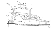
- FIG. 1 shows a device 10 for the descent of eels at hydraulic structures.
- a watercourse F in its flow direction S is subdivided by a hydraulic structure W into an upstream upper water O and downstream of the hydraulic structure W underwater U flowing.
- a fish protection system in the form of a rake 20 is arranged in the upper water O. It obstructs the living beings that follow the flow direction S in the flowing water F, the entry E into the hydraulic structure W, which may contain, for example, a turbine or the like.
- the fish protection system 20 is preferably formed mechanically as a rake. It is for example a bar screen.
- a fish pass 60 For living creatures arriving in upper water layers of the upper water, a fish pass 60 is provided for bypassing the hydraulic structure, with an entrance P, which can be found, for example, near the embankment in the upper water area.
- a manifold 30 arranged on the sole side is provided. This leads to a diversion system 50. The latter in turn empties into the fish pass 60.
- the collecting line 30 for eels is always easy to find, is located in front of this in the area of the sole B a bar-shaped or bar-shaped element 40, which generates a flow shadow D between itself and the fish protection systems 20.
- This will the inflow L to the openings of the manifold 30 for the eels clearly visible.
- the eels can now follow these flows L in the protection of the flow shadow, after they have been prevented by the fish protection system 20, for example, from following the flow direction S into the hydraulic structure W.
- this is formed with a bypass line 51, wherein the collecting line 30 opens directly into an ascending part 52 of the bypass line 51 serving as a lifting line. It is important that the upstream side entry into the diversion system 50 deep under water in the upper water O and the underwater side outlet is under water in the fishway 60. The underwater outlet is so over-inflated that in no case air can penetrate.
- the eel follows the flow L in the bypass line 51 further into the descending part 53 of the bypass line 51 before it enters the fish passage 60 at the mouth M of the bypass line 51.
- the embodiment shown with a bypass line 51 of the diversion system 50 has the advantage that, even with difficult water levels (extreme high or low water), a sudden pressure drop at the openings of the manifold 30, at which the animals recoil and do not immigrate, is avoided. This could otherwise lead to damage to the animals transported by the stream. With the aid of the bypass solution shown, however, the eel and other organisms using the device are safely guided into the fishway 60 and thus around the hydraulic structure W under physiological pressure conditions and with a controlled flow rate.
- an overflow 61 is arranged on the fish pass 60 in the area of the bypass opening M. This relieves possibly through the Bypasseinmündung become too large flows harmless into the underwater.
- the Supplementing the flow into the fishway whose entrainment in the underwater significantly strengthen and thus improve the findability for ascending fish.
- FIG Fig. 1 a pumping and flushing system 70 and at the high point 54 of the bypass line 51 a slide 55. With this slide 55, the bypass line 51 can be closed. Furthermore, the pumping and flushing system 70 has an air valve 73, which is arranged on a storage container 71, and a vacuum pump 72. It is advantageous if the storage container 71 is connected to the bypass line 51 via a side connection 56 at the high point 54. Suitably, the vacuum pump 72 and the air valve 73 are arranged at the high point of the reservoir 71. This pumping and flushing system 70 is advantageous not only for cleaning, but also with regard to the start-up of the bypass line 51 functioning as a lift line.
- the siphon pipe 51 assumes its function and a suction flow L arises between the upper water O and the underwater U, along which the eels can be transported.
- the vacuum pump 72 can then be turned off.
- the vacuum pump 72 is restarted. It then sucks the air out of the reservoir 71 so that it fills with water through the side port 56 from the bypass line 51.
- the slider 55 is closed when the lift line is running.
- the water columns in the rising in the sloping branch (52, 53) are initially held by the prevailing negative pressure in the bypass line 51.
- the air valve 73 is opened on the reservoir 71, it comes to pressure equalization.
- the pumped up water flows abruptly in the rising part of the line 52 back and flushes the manifold 30, the openings 31 of the manifold 30 and the area in front of the openings.
- the slider 55 is initially closed.
- the vacuum pump 72 is started and runs until the bypass line 51 at the high point 54 is evacuated. If then the slider 55 is opened, the suction flow L between upper water O and underwater U is restored. The eels can now be transported back to the flow L through the bypass line 51 from the upper water O into the underwater U.
- the manifold 30 is formed as a tube, which is a simple construction of the device to the good.
- the manifold is arranged on a base 32 on the bottom B of the watercourse.
- the openings 31, 33 of the manifold 30 remain free. These are in the embodiment shown to the sole B out and that predominantly on the incoming flow of the watercourse side facing the manifold 30. This makes them particularly good for both the eels, which have retreated into the flow shadows, as well as for at Sole B to reach incoming eels A.
- These pass through the flow shadow generating element 40, for example in the region of one of the slip openings 42 and can swim directly through one of the openings 31 in the manifold 30.
- Eels that are in the area of the flow shadow D can sense the suction flow and are either also lured through the openings 31 in the manifold. Or they can use an opening 33 arranged in the flow direction S for entry into the collecting line 30.
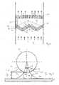
- the flow shadow generating element 40 is, as in the embodiment of Fig. 2 shown, made of bristle elements 41.
- the bristles 44 are made of flexible plastic, which has the advantage that a vegetation of the sole is imitated. Other embodiments are conceivable.
- the bristle elements 41 as in the embodiment have a trapezoidal base and be arranged so that the bases of the successive bristle elements 41 are arranged alternately mirror-inverted. In this way, through openings 41 in the flow shadow-generating element 40 can be created without further means alone by the arrangement of the bristle elements 41 (see Fig. 3 ).
- These are advantageously not arranged directly in the flow direction S, but at an angle ⁇ thereto. As a result, the flow is already weakened in the slip-through opening 42 and it is prevented that in the area of the orifice 43 of the slip-through openings 42 in the area of the flow shadow D, turbulence to be irritated occurs.
- the bristle elements 41 are not massively opposite the flow of the flowing water arriving in the direction of flow S, but they are permeable to a certain extent for the flow. This also prevents an abrupt flow stop and the emergence of irritating turbulence behind the element 40. It is advantageous if the bristles 44 are formed elastically. They can be vibrated by the flow. As a result, the bristle elements 41 purify themselves to a certain extent.
- FIG. 4 and FIG. 5 show a further embodiment of the manifold 30 for a device according to the invention and for a diversion system according to the invention.
- the collecting line 30 is arranged in a zigzag fashion over the sole B of the watercourse F.
- the bending angle ⁇ of the collecting line can be between 0 ° and 90 °, preferably between 45 ° and 80 °, particularly preferably 60 °.
- the openings 31 are arranged in the concave corners K of the manifold 30 and thus opened alternately in and against the flow direction S. In this way, the legs 36 of the manifold 30, which include one of the concave corners K act like a funnel, which feeds the eels on the opening 31.
- At least one, preferably two guide plates 34 are arranged below the manifold 30.
- This may be, for example, a bent sheet metal or a sawn plastic pipe which is arranged at a certain angle ⁇ to the bottom B of the flowing water F.
- the angle ⁇ describes how much the pipe sections or the bent sheet is tilted relative to the sole, preferably angles between 0 and 45 °, more preferably between 0 and 22 °, most preferably 15 °.
- the end 341 of the guide apron 34 facing the manifold 30 terminates immediately at the lower opening edge 311 in the region of the openings 31.
- eels floating along the guide apron 34 can easily enter the openings 31, following the lock stream L.
- the lower end 311 of the openings 31 is not arranged directly at the vertex HP of the manifold 30, but it is at an angle ⁇ / 2 thereof.
- ⁇ may be between 0 and 180 °, preferably between 0 and 90 °, particularly preferably 30 °.
- the distance H between the lower end of the opening 311 and the sole B is thus preferably greater than the distance h between the vertex HP of the manifold 30 and the sole B.
- the manifold 30 and, if present, the shadow creating member 40 may be lifted out of the water for inspection and cleaning on side skids.
- the connection to the bypass line 51 can be realized for example by an automatic clutch.
- the diversion system 50 is equipped not only with one, but also with two slides 55. In this case, one can be arranged in front of and one after the side connection 56. In this case, it would be possible for flushing the rising part 52 of the bypass line 51 to close the arranged after the side port 56 slide 55, for flushing the descending part 53 of the bypass line 51, however, arranged in front of the side port 56.
- the fish deflector 20 does not necessarily have to be a rake, it is also conceivable to roll netting or the like. Also, the fish deflector 20 does not necessarily have to be designed purely mechanically, because it is too Combinations of, for example, mechanical and electrical fish protection devices conceivable. Also conceivable is the support of the mechanical fish deflector 20 by light signals or deliberately generated water turbulence, for example by means of air bubble flows. Other variations are conceivable, for example the introduction of fragrance attractants.
- the manifold 30 may instead of a pipe, which is made of plastic, for example, be a brick or cast concrete channel. Although this is more expensive to manufacture, it may mean a more stable and less prone to repair.
- the manifold 30 and the flow shadow generating element 40 could also be mounted on a common base plate that can be lifted out of the water with a crane or with the appropriately equipped rake cleaner for inspection purposes. For this purpose, a detachable pipe coupling can be attached to the ascending branch 53 of the bypass line 51.
- the sidewall FB of the watercourse F can be either a natural embankment or other river bed boundary as well as an artificially mounted sidewall for enclosing the hydraulic structure W.
- the flow shadow generating element 40 also offers many possibilities for the design.
- sail-like surface elements arranged offset to one another are also conceivable. These may be elastic, for example, and so, similar to the bristle elements 41 simulating plant growth of the riverbed. It is also conceivable that the flow shadow D is generated with the help of natural stones, which are arranged upstream of the manifold 30.
- through-flow openings formed in the element 40 can avoid undesired turbulence in the flow shadow D.
- a block of soft plastic material with through-flow and through-flow openings is drilled through, or that such a block can be cut in various directions or cut to size.
Abstract
Description
Die Erfindung betrifft eine Vorrichtung für den Abstieg von Aalen an Wasserbauwerken gemäß dem Oberbegriff von Anspruch 1 sowie ein Umleitungssystem nach Anspruch 13 und eine Vorrichtung für den Abstieg von Aalen an Wasserbauwerken nach Anspruch 15.The invention relates to a device for the descent of eels on hydraulic structures according to the preamble of claim 1 and a diversion system according to claim 13 and a device for the descent of eels to hydraulic structures according to claim 15.
Aale (Anguillidae) sind begehrte Speisefische, jedoch in ihrem Bestand weltweit stark bedroht. Ein besonderes Problem dabei ist, dass es bisher unmöglich ist, Aale - beispielsweise zum Verzehr - in Kultur bis zum Erwachsenenstadium zu züchten. Als katadrome Wanderfische weisen sie außerdem eine weitere Besonderheit auf. Sie laichen im Meer, wandern als Larven bzw. Glasaale weite Strecken zu Flussmündungen und schließlich als sogen. Steigaale im Süßwasser flussaufwärts. Nachdem sie Jahre später in den oberen Flussregionen das Adultstadium erreicht haben, treten sie die Rückwanderung zu den Laichplätzen in der Sargassosee an. Dabei legen sie in stetigen Fliessgewässern häufig ein für sie spezielles und typisches, energiesparendes Wanderverhalten an den Tag: Sie lassen sich einfach im Mittelwasser oder sogar dicht über der Sohle mit nur wenigen Schwimmbewegungen in Strömungsrichtung treiben. Treffen sie dabei auf ein Hindernis, wird sofort ein nahezu 180° der Strömung entgegensetztes Fluchtverhalten gezeigt. Dabei versucht der Aal zur Flusssohle abzutauchen und dort Schutz zu finden. Eine Quersuchbewegung entlang des Hindernisses, wie sie andere Fische zeigen, wird in der Regel nicht ausgeführt. Vielmehr orientieren sich die Aale einerseits an der Strömungsrichtung selbst, was sie zwangsweise immer wieder zu dem Hindernis führt. Andererseits spielt die olfaktorische Orientierung eine große Rolle, was aber ebenfalls häufig durch natürlich auch in der Hauptströmungsrichtung verteilte Duftstoffe einen erneuten Zusammenstoss mit dem Hindernis hervorruft.Eels ( Anguillidae ) are coveted edible fish, but are threatened worldwide. A particular problem with this is that it has so far been impossible to breed eels - for example for consumption - in culture until they reach the adult stage. As catadromous migratory fish, they also have another special feature. They spawn in the sea, migrate as larvae or glass eels long distances to estuaries and finally as so-called. Steigaale in fresh water upstream. Years later, in the upper reaches of the river, they reach the adult stage and begin the return migration to the spawning grounds in the Sargasso Sea. In continuous flowing waters, they often display a specific and typical, energy-saving hiking behavior that is unique to them: they can be easily installed in the water Drive medium water or even just above the sole with only a few floating movements in the direction of flow. If they encounter an obstacle, an escape behavior of almost 180 ° is immediately demonstrated. The eel tries to dive to the river bottom and find protection there. A cross-search along the obstacle, as shown by other fish, is usually not carried out. Rather, the eels are oriented on the one hand to the flow direction itself, which inevitably leads them repeatedly to the obstacle. On the other hand, the olfactory orientation plays an important role, but this also often causes a renewed collision with the obstacle by naturally distributed also in the main flow direction fragrances.
Unter den bekannten Wasserbauwerken stellen Wasserkraftanlagen eine besondere Gefahr für die flussabwärts wandernden Aale dar. Zwar sind diese häufig mit Fischabweisern versehen, die einen Einstieg von Fischen in die Anlage verhindern sollen. Umgehende Fischpässe, die beispielsweise junge Lachse oder Meerforellen beim Absteigen nutzen, sind jedoch aufgrund ihres besonderen Verhaltens für die Aale meistens nicht auffindbar. Da aber für die Aale als katadrome Wanderfischart ein großer biologischer Drang zum Absteigen herrscht, versuchen sie mit allen Mitteln das Hindernis zu überwinden und geraten dabei häufig in die Turbinen der Wasserkraftanlagen. Dies stellt, neben der im großen Stil betriebenen Glasaal-Fischerei und parasitärem Befall, eine der großen Bedrohungen für den Erhalt der Arten dar. Es ist daher dringend geboten, eine für Aale auffindbare Umgehungsmöglichkeit solcher Wasserbauwerke zu schaffen.Among the well-known hydraulic structures, hydropower plants pose a particular danger to eels migrating downstream. These are often provided with fish deflectors to prevent fish from entering the system. However, due to their special behavior for the eels, it is usually impossible to find outgoing fish passes that use young salmon or sea trout when descending, for example. But since the eels, as a catadromous migratory fish species, have a great biological urge to descend, they try by all means to overcome the obstacle and often fall into the turbines of the hydroelectric power plants. This is one of the major threats to the preservation of species in addition to the large-scale Glasaal fishery and parasitic infestation. It is therefore imperative to create an ecosystem-like bypass for such structures.
Auch andere, z.B.
Ziel der Erfindung ist es daher, diese und weitere Nachteile des Standes der Technik zu beseitigen und eine Vorrichtung für den Abstieg von Aalen an Wasserbauwerken zu schaffen, die es den Aalen aber auch anderen im Fliessgewässer absteigenden Lebewesen ermöglicht, ein Wasserbauwerk sicher zu umgehen. Vor allem soll die Erfindung eine Lösung bereitstellen, die ein Auffinden des Umleitungssystems durch die Aale auch tatsächlich sicherstellt. Die Vorrichtung soll ferner mit einfachen Mitteln kostengünstig aufgebaut sein. Angestrebt wird zudem eine einfache Handhabung, die auch nach Jahren im Betrieb funktioniert und einfach zu reinigen ist.The aim of the invention is therefore to eliminate these and other disadvantages of the prior art and to provide a device for the descent of eels on hydraulic structures, which allows the eels but also other descending creatures living in rivers to safely bypass a hydraulic structure. Above all, the invention is intended to provide a solution that actually ensures finding the diversion system through the eels. The device should also be constructed inexpensively by simple means. The aim is also a simple handling that works even after years of operation and is easy to clean.
Aufgabe der Erfindung ist es außerdem ein Umleitungssystem für Aale zur Umgehung eines Wasserbauwerkes zur Verfügung zu stellen, das mit einfachen Mitteln kostengünstig aufgebaut ist und welches das Auffinden durch die Aale im Oberwasser des Wasserbauwerkes erleichtert. Außerdem soll es bei einer Vorrichtung für den Abstieg von Aalen an Wasserbauwerken einsetzbar sein.The object of the invention is also to provide a diversion system for eels for bypassing a hydraulic structure available, which is constructed inexpensively by simple means and which facilitates the finding by the eels in the upper water of the hydraulic structure. In addition, it should be used in a device for the descent of eels to hydraulic structures.
Bei einer Vorrichtung für den Abstieg von Aalen an Wasserbauwerken vor einem im Oberwasser angeordneten Fischschutz mit einem Umleitungssystem zur Umgehung des Wasserbauwerkes, das zur Aufnahme der Aale im Oberwasser wenigstens eine Sammelleitung mit wenigstens einer Öffnung, die im Bereich der Sohle des in Strömungsrichtung fließenden Fliessgewässers angeordnet ist, sieht die Erfindung vor, dass stromaufwärts der Öffnung oder der Öffnungen der Sammelleitung ein Strömungsschatten erzeugendes Element angeordnet ist.In a device for the descent of eel to hydraulic structures in front of a arranged in the upper water fish protection with a diversion system to bypass the hydraulic structure, for receiving the eels in the upper water at least one manifold with at least one opening in the region of the sole of in Flow direction is arranged flowing flow, the invention provides that upstream of the opening or the openings of the manifold a flow shadow generating element is arranged.
Dabei ist der durch das Strömungsschatten erzeugende Element hervorgerufene Strömungsschatten von besonderer Bedeutung. Dieser herrscht vorzugsweise im Bereich der Sammelleitung an der Sohle des Fließgewässers zwischen seinem erzeugenden Element und dem Fischschutzsystem. Besonders bevorzugt liegen dabei die Öffnungen der Sammelleitung im Strömungsschatten. Es ist weiter vorgesehen, dass eine Strömung in der Sammelleitung die Aale direkt in das Umleitungssystem leitet. Diese Strömung erzeugt einen Sog, der durch die Öffnungen der Sammelleitung wahrnehmbar ist. Es ist weiterhin vorgesehen, dass mittels einer zielgerichteten hydraulischen Dimensionierung dafür gesorgt wird, dass an allen Öffnungen die Strömungsverhältnisse annähernd gleich sind.In this case, the flow shadow caused by the flow shadow element is of particular importance. This preferably prevails in the region of the collecting line at the bottom of the river between its generating element and the fish protection system. Particularly preferred are the openings of the manifold in the flow shadow. It is further contemplated that a flow in the manifold directs the eels directly into the diversion system. This flow creates a suction which is perceptible through the openings of the manifold. It is further provided that by means of a targeted hydraulic dimensioning is ensured that at all openings, the flow conditions are approximately equal.
Nach einer Kollision mit dem Fischschutzsystem geraten die Aale bei ihrer nach unten gerichteten Flucht automatisch in den Bereich des Strömungsschattens. Dieser ermöglicht es den Aalen, sich vor dem Fischschutzsystem eine kurze Strecke in Querrichtung zur eigentlichen Strömung zu bewegen und eine Abstiegsmöglichkeit zu suchen. Weiter können die Aale nun im Strömungsschatten die im Verhältnis zur Strömung des Fließgewässers schwache Sogwirkung der Sammelleitung wahrnehmen. Auf diese Weise ist die Sammelleitung für die Aale stets gut auffindbar und sie können dem Lockstrom in das für sie sichere Umleitungssystem folgen.After a collision with the fish protection system, the eels automatically fall into the area of the flow shadow during their downward flight. This allows the eels to move in front of the fish protection system a short distance in the transverse direction to the actual flow and to seek a descent possibility. Next, the eels can now perceive in the flow shadow the weak in relation to the flow of the flowing water suction of the manifold. In this way, the collection line for the eel is always easy to find and they can follow the lure flow in the safe bypass system for them.
Sinnvollerweise ist das Strömungsschatten erzeugende Element an der Sohle des Fließgewässers angeordnet und riegelförmig oder balkenförmig ausgebildet, denn so ist es möglich, einen Strömungsschatten zu erzeugen, der sich über die gesamte Breite des zu versperrenden Hindernisses und des davor angeordneten Fischschutzsystems bzw. der Sammelleitung erstreckt.It makes sense that the flow shadow generating element is arranged at the bottom of the watercourse and formed bar-shaped or bar-shaped, because so it is possible to create a flow shadow that extends over the entire width of the obstruction to be obstructed and arranged upstream of the fish protection system or the manifold.
Um nicht nur Aalen, die im Mittelwasser angetrieben kommen und von dem Fischschutzsystem aus in den Bereich des Strömungsschatten abtauchen, sondern auch Aalen und anderen Fischen, die bereits an der Sohle des Fließgewässers ankommen, das Passieren des Strömungsschatten erzeugenden Elementes zu ermöglichen, ist vorgesehen, dass das Strömungsschatten erzeugende Element Durchschlupföffnungen aufweist. Diese sind darüber hinaus von Vorteil, wenn Aale vom Fischschutzsystem aus in einen zu weit stromaufwärts gelegenen Bereich der Sohle abtauchen und so gegebenenfalls auf das Strömungsschatten erzeugende Element selbst als Hindernis treffen würden.In order to enable not only eels that are driven in the middle water and from the fish protection system in the area of the flow shadow, but also eels and other fish that arrive at the bottom of the running water to allow the passage of the flow shadow generating element is provided the flow shadow-generating element has slip-through openings. These are also beneficial if eels from the fish protection system in a too far upstream region of the sole dive and so possibly hit the flow shadow generating element itself as an obstacle.
Die Durchschlupföffnungen sollten in einem Winkel zur Strömung angeordnet sein, was einerseits die Wucht der Strömung beim Durchströmen der Durchschlupföffnung mindert.The slip-through openings should be arranged at an angle to the flow, which on the one hand reduces the force of the flow when flowing through the slip-through opening.
Bei einer vorteilhaften Ausgestaltung des Strömungsschatten erzeugenden Elements in Form von Borstenelementen können diese zunächst auch als Versteckmöglichkeit für die Aale dienen. Die Borstenelemente sind dann einer für die Aale und für andere Bewohner von der Flusssohle nahen Bereichen gewohnten, natürlichen Umgebung relativ ähnlich. Dadurch wird auch das Risiko, dass die Tiere vor dem Strömungsschatten erzeugenden Element zurückschrecken und es nicht passieren, minimiert. Auch können Borstenelemente zumindest teilweise von der ankommenden Strömung schwach durchströmt werden und stellen so keine massive, möglicherweise für störende Turbulenzen sorgende Blockade dar. Stattdessen kommt es einfach zu einer Abschwächung aber nicht zu einer deutlichen Richtungsänderung der Strömung. Dies kann bei anderen Ausführungsvarianten mit Hilfe von Durchstromöffnungen realisiert werden. Insgesamt bliebt so zunächst die für die Aale und andere absteigende Organismen wichtige Hauptrichtung der Strömung erhalten, sie führt sie jedoch in den Strömungsschatten zwischen dem Strömungsschatten erzeugenden Element und dem Fischschutzsystem. Dort ist die Hauptströmung dann so sehr abgeschwächt, dass die Tiere die in die Sammelleitung und das Umleitungssystem führenden Senkenströmung gut wahrnehmen und dieser in die Öffnungen der Sammelleitung folgen können.In an advantageous embodiment of the flow shadow generating element in the form of bristle elements, these can initially serve as a hiding place for the eels. The bristle elements are then relatively similar to a natural environment common to eels and other inhabitants of the riverbed. This also minimizes the risk that the animals will shy away from the shadowing element and not pass it. Also bristle elements can be at least partially flowed through by the incoming flow weak and thus do not constitute massive, possibly for disturbing turbulence worrying blockage. Instead, it simply comes to a weakening but not to a significant change in direction of the flow. This can be realized in other embodiments by means of flow openings. Overall, the main direction of the flow, which is important for the eels and other descending organisms, initially remains, but it leads them into the flow shadows between the flow shadow-generating element and the fish protection system. There, the mainstream is then so much attenuated that the animals are well aware of the sink flow leading into the manifold and diversion system and can follow it into the openings of the manifold.
Besonders vorteilhaft ist es außerdem, wenn die Borsten der Borstenelemente elastisch sind. Sie können dann beispielsweise durch die Strömung in Vibration versetzt werden. Dies kann wiederum zu einem gewissen Selbstreinigungseffekt führen, indem kleineres Treibgut und Detritus mit Hilfe der Schwingung der Borsten durch die Borstenelemente hindurch befördert wird.It is also particularly advantageous if the bristles of the bristle elements are elastic. They can then be vibrated, for example, by the flow. This in turn can lead to a certain self-cleaning effect by smaller debris and detritus is conveyed by means of the vibration of the bristles through the bristle elements.
Zweckmäßig ist vorgesehen, dass die Sammelleitung quer zur Strömung angeordnet ist. Konstruktiv ist es günstig, wenn die Sammelleitung ein Rohr ist. Dies ist vor allem in Hinblick auf eine einfache und materialgünstige Bauweise positiv. Weiterhin ist es von Vorteil, wenn die Sammelleitung mindestens den 5 bis 10fachen Durchmesser des Durchmessers eines adulten Aales hat, aber es sind auch deutlich größere Sammelleitungen vorstellbar. Besonders günstig ist es dabei, wenn die Sammelleitung zick-zack-förmig ausgebildet ist. Dabei kann die Sammelleitung bevorzugt flach über der Sohle des Fließgewässers liegen.Suitably, it is provided that the manifold is arranged transversely to the flow. Constructively, it is advantageous if the manifold is a pipe. This is positive, especially with regard to a simple and material-favorable design. Furthermore, it is advantageous if the manifold has at least 5 to 10 times the diameter of an adult eel diameter, but also significantly larger manifolds are conceivable. It is particularly advantageous if the manifold is formed zig-zag-shaped. In this case, the manifold may preferably lie flat over the bottom of the watercourse.
Verschiedene Ausführungsvarianten sind in Bezug auf die Anordnung der Öffnungen der Sammelleitung vorstellbar. So ist es einerseits möglich alle Öffnungen entgegen der Strömungsrichtung des Fließgewässers auszurichten. Vorstellbar ist auch, dass die Öffnungen abwechselnd in und entgegen der Strömungsrichtung oder auch dass die meisten Öffnungen entgegen der Strömungsrichtung und einige gelegentlich in Strömungsrichtung ausgerichtet sind. Wichtig ist, dass eine ausreichende Anzahl der Öffnungen dorthin ausgerichtet ist, wo der Strömungsschatten sich befindet, denn es ist zu erwarten, dass die meisten Tiere nachdem sie vom Fischschutzsystem zurückgeschreckt sind bzw. wenn sie an der Sohle ankommen, im Strömungsschatten des Strömungsschatten erzeugenden Elements nach dem Weg suchen.Various embodiments are conceivable with respect to the arrangement of the openings of the manifold. So it is on the one hand possible to align all openings against the flow direction of the watercourse. It is also conceivable that the openings are alternately in and against the flow direction or that most openings are oriented counter to the flow direction and some occasionally in the flow direction. It is important that a sufficient number of the openings are aligned to where the flow shadow is located, because it is expected that most animals, after they have recoiled from the fish protection system or when they arrive at the sole, in the flow shadow of the flow shadow generating element looking for the way.
Wichtig ist, dass die Öffnungen der Sammelleitung annähernd gleichmäßig über die Länge der Sammelleitung verteilt sind und dass beispielsweise mit hydraulischen Mitteln dafür gesorgt wird, dass durch alle Löcher annähernd der gleiche Durchfluss fließt, so dass davon annähernd die gleiche Sogwirkung ausgeht. Durch möglichst nicht zu große und regelmäßige Abstände zwischen den Öffnungen wird die Chance für die nur im geringen Maß Quersuchbewegungen ausführenden Tiere erhöht, eine der Öffnungen auch tatsächlich zu finden.It is important that the openings of the manifold are distributed approximately uniformly over the length of the manifold and that, for example, by hydraulic means is ensured that flows through all the holes approximately the same flow, so that out approximately the same suction effect. By not too large and regular distances between the openings, the chance for the animals performing only a small amount of cross-search movements is increased to actually find one of the openings.
Weiterhin ist es wichtig, dass die Öffnungen der Sammelleitung im Bereich des von dem Strömungsschatten erzeugenden Elements erzeugten Strömungsschatten liegen. Dadurch ist gewährleistet, dass der Lockstrom, der die Aale in die Öffnungen führen soll, nicht von der Hauptströmung des Fließgewässers überdeckt wird.Furthermore, it is important that the openings of the manifold lie in the area of the flow shadows generated by the flow shadow generating element. This ensures that the lint, which is intended to guide the eels into the openings, is not covered by the main stream of the watercourse.
Ist die Sammelleitung zick-zackförmig, so ist es besonders günstig, wenn die Öffnungen in den konkaven Eckpunkten der Sammelleitung angeordnet sind. Die Aale können auf diese Weise nicht nur durch den Lockstrom zu den Öffnungen geführt werden, sondern auch durch die trichterartig auf die Öffnungen zuführende Geometrie der Sammelleitung. Ebenfalls bei einer zick-zackförmigen Sammelleitung aber auch bei einer geraden Leitung können weitere Öffnungen jeweils in einer Ecke zwischen einem Ende der Sammelleitung und einer Seitenwand des Fließgewässers vorhanden sein. Dabei ist es sowohl denkbar, dass es sich bei der Seitenwand um eine natürliche Böschung handelt, als auch dass eine künstliche Seitenwand bei der Montage der Vorrichtung oder beim Bau des Wasserbauwerkes eingefügt wird.If the collecting line is zig-zag, it is particularly favorable if the openings are arranged in the concave corner points of the collecting line. The eels can be guided in this way not only by the flow of lures to the openings, but also by the funnel-like on the openings feeding geometry of the manifold. Also in a zigzag-shaped manifold but also in a straight line further openings may be present in each case in a corner between one end of the manifold and a side wall of the watercourse. It is also conceivable that it is the side wall is a natural embankment, as well as that an artificial side wall is inserted during assembly of the device or during construction of the hydraulic structure.
Von besonderem Vorteil ist es dabei, wenn zusätzlich unterhalb der Sammelleitung wenigstens eine, bevorzugt zwei Leitschürzen angebracht sind. Diese verhindern ein Unterschwimmen der Sammelleitung.It is particularly advantageous if at least one, preferably two guide aprons are additionally mounted below the collecting line. These prevent underflow of the manifold.
Bei der Ausgestaltung des Umleitungssystems ist es von Vorteil, wenn das Umleitungssystem eine Bypassleitung aufweist. Dabei ist es zweckmäßig, wenn die Sammelleitung in die Bypassleitung und diese wiederum in passender Höhe in ein Rinnensystem mündet, das die absteigenden Aale sicher in das Unterwasser führt. Hierzu eignet sich am besten der Fischpass. Durch diese Bypassleitung kann ein für die Aale und auch für andere die Umleitung nutzende Tiere schädlicher Druckabfall verhindert werden, der ansonsten entstehen könnte, wenn das Sammelrohr direkt in das Unterwasser mündete. In diesem Zusammenhang ist es auch von Vorteil, wenn an dem Fischpass stromabwärts der Mündung des Bypasses ein Überlauf ausgebildet ist. So kann der durch die infolge der Einnmündung des Aalabstiegs erhöhte Durchfluss wieder auf das normale Maß zurückgeführt werden ohne eine Gefahr sowohl für die über den Bypass in den Fischpass gelangenden als auch für andere den Fischpass nutzenden Tiere. Die Beileitung des Durchflusses der Aalabstiegsanlage in den Fischpass kann bei entsprechender Auslegung des Fischpasses darüber hinaus den Vorteil haben, dass der Lockstrom des Fischpasses deutlich verstärkt wird, so dass der Fischpass für aufsteigende Fische besser auffindbar wird.In the embodiment of the diversion system, it is advantageous if the diversion system has a bypass line. It is expedient if the manifold into the bypass line and this in turn opens at the appropriate height in a gutter system that leads the descending eels safely into the underwater. The fish pass is best suited for this purpose. By means of this bypass line, a harmful pressure drop can be prevented for the eels and also for other animals using the diversion, which could otherwise result if the collecting tube led directly into the underwater. In this context, it is also advantageous if an overflow is formed at the fish pass downstream of the mouth of the bypass. In this way, the increased flow rate due to the entry of the eel down can be restored to normal without posing a risk to both the bypass and the fish pass. The addition of the flow of the eel downpipe into the fishway can also have the advantage, with appropriate design of the fishway, that the lure of the fishway is significantly increased, so that the fish pass for ascending fish is easier to find.
Weiterführende Ausgestaltungsvarianten sehen vor, dass die Bypassleitung mit einem stromaufwärts liegenden aufsteigenden Teil und einem stromabwärts liegenden abfallenden Teil ausgebildet ist. Dazwischen kann ein Hochpunkt ausgebildet sein. Die Bypassleitung funktioniert dann als Heberleitung, bei der es möglich ist, die Tiere zunächst aus der Sammelleitung über das Flussniveau zu heben und dann kontrolliert hinab in den Fischpass gleiten zu lassen.Further embodiment variants provide that the bypass line is formed with an upstream ascending part and a downstream descending part. In between, a high point can be formed. The bypass line then works as a siphon line, where it is possible to first lift the animals out of the manifold above the river level and then let them slide down into the fish pass in a controlled manner.
Ein im Hochpunkt oder im abfallenden Ast angeordneter Schieber ist ebenfalls von Vorteil. Dieser ermöglicht, die Bypassleitung z.B. zu Wartungs- und Reinigungszwecken zu verschließen. Dazu ist auch ein über einen Seitenanschluss mit dem Umleitungssystem verbundenes Pump- und Spülsystem zweckmäßig. Der am Umleitungssystem ausgebildete Seitenanschluss ist bevorzugt im Hochpunkt der Bypassleitung vor dem Schieber angeordnet, wodurch das Umleitungssystem mit dem Pump- und Spülsystem verbunden wird.A slider arranged in the high point or in the descending branch is also advantageous. This makes it possible to close the bypass line eg for maintenance and cleaning purposes. For this purpose, a connected via a side port with the bypass system pumping and flushing system is appropriate. The side connection formed on the diversion system is preferably arranged in the high point of the bypass line in front of the slide, whereby the diversion system is connected to the pumping and flushing system.
Zweckdienlich ist das Pump- und Spülsystem mit einem Vorratsbehälter ausgebildet. Auch ist in dem Fall, dass die Bypassleitung als Heberleitung angeordnet ist, vorgesehen, dass das Pump- und Spülsystem mit einer Vakuumpumpe ausgestattet wird. Diese dient beispielsweise dazu, bei offenem Schieber die Luft aus der Bypassleitung zu saugen und diesen Heber damit anspringen zu lassen. Bei geschlossenem Schieber dient die Vakuumpumpe dazu, den Vorratsbehälter über den Seitenanschluss mit Wasser aus dem Umleitungssystem zu füllen. Dazu ist es von Vorteil, wenn die Vakuumpumpe am Vorratsbehälter angeordnet bzw. angeschlossen ist.Conveniently, the pumping and flushing system is formed with a reservoir. Also, in the case that the bypass passage is arranged as a lift line, it is provided that the pumping and flushing system is equipped with a vacuum pump. For example, this serves to suck the air out of the bypass line when the slide is open and to let this lift start. When the slide is closed, the vacuum pump serves to fill the reservoir via the side port with water from the bypass system. For this purpose, it is advantageous if the vacuum pump is arranged or connected to the reservoir.
Zur Belüftung des Vorratsbehälters und zum Ablassen des Wassers aus dem gefüllten Vorratsbehälters oder zum Unterbrechen der Strömung in der Bypassleitung ist die Ausbildung des Pump- und Spülsystems mit einem Luftventil vorteilhaft. Dieses kann ebenfalls am Vorratsbehälter angeordnet sein. Auf diese Weise ist ein sehr einfaches Durchspülen zur Reinigung der Bypassleitung vorstellbar. Bei geschlossenem Schieber und Luftventil wird zunächst mit Hilfe der Vakuumpumpe der Vorratsbehälter mit Wasser aus der Bypassleitung gefüllt. Anschließend wird das Luftventil geöffnet. Dadurch strömt das zuvor hochgepumpte Wasser aus dem Vorratsbehälter zurück durch die Bypassleitung in die Sammelleitung und durch die Öffnungen nach außen. Durch diese Strömung werden die Leitung, die Sammelleitung, die Öffnungen und der Bereich außen vor den Öffnungen effektiv gereinigt.For ventilation of the reservoir and for discharging the water from the filled reservoir or to interrupt the flow in the bypass line, the formation of the pumping and flushing system with an air valve is advantageous. This can also be arranged on the reservoir. In this way, a very simple flushing for cleaning the bypass line is conceivable. When the slide valve and air valve are closed, the reservoir is first filled with water from the bypass line by means of the vacuum pump. Then the air valve is opened. As a result, the previously pumped up water from the reservoir flows back through the bypass line in the manifold and through the openings to the outside. This flow effectively cleans the conduit, manifold, openings, and the area outside the openings.
Neben der Spülung durch das Auslaufen eines Vakuumbehälters sind auch Spülungen aus einem über ein Pumpe gefüllten, unterdruckfreien Behälter denkbar und möglich. Darüber hinaus ist auch die Rückspülung des Systems direkt über eine große Pumpe möglich.In addition to the rinse by the leakage of a vacuum container and rinses from a pump-filled, vacuum-free container are conceivable and possible. In addition, the backwashing of the system is possible directly via a large pump.
Das Fischschutzsystem dient als Hindernis, um den Einstieg der mit der Strömung ankommenden Aale in das Wasserbauwerk zu verhindern. Zweckmäßig ist es dazu im Oberwasser angeordnet und zwar vor einem möglichen Einstieg in das Wasserbauwerk, beispielsweise vor dem zuleitenden Rohr einer Turbine eines Wasserkraftwerkes. Vorteilhaft ist auch, wenn das Fischschutzsystem mechanisch ausgebildet ist, beispielsweise in Form eines Rechens. Dadurch wird ein versehentliches Passieren des Fischschutzsystems stets zuverlässig verhindert.The fish protection system serves as an obstacle to prevent the entry of the flow arriving eels into the hydraulic structure. Appropriately, it is arranged in the upper water and that before a possible entry into the hydraulic engineering, for example in front of the pipe leading a turbine of a hydroelectric power plant. It is also advantageous if the fish protection system is mechanically formed, for example in the form of a rake. This always reliably prevents accidental passing of the fish protection system.
Bei einem Umleitungssystem für Aale zur Umgehung eines Wasserbauwerkes, mit einer im Oberwasser angeordneten Sammelleitung, die im Bereich der Sohle des in Strömungsrichtung fließenden Fliessgewässers angeordnet ist, wenigstens eine Öffnung zur Aufnahme der Aale aufweist und in einer Bypassleitung mündet, sieht die Erfindung vor, dass die Sammelleitung zick-zackförmig ausgebildet ist und dass unterhalb der Sammelleitung wenigstens eine Leitschürze angeordnet ist.In a diversion system for eels for bypassing a hydraulic structure, with a collecting line arranged in the upper water, which is arranged in the region of the sole of the flowing in the flow direction flowing water, at least one opening has for receiving the eels and opens into a bypass line, the invention provides that the manifold is formed zigzag and that at least one guide apron is disposed below the manifold.
Vorteilhaft ist es dabei, wenn mindestens eine Öffnung der Sammelleitung in einer konkaven Ecke der Sammelleitung ausgebildet ist. Die Aale können auf diese Weise nicht nur durch den Lockstrom zu den Öffnungen geführt werden, sondern auch - wie oben beschrieben - durch die trichterartig auf die Öffnungen zuführende Geometrie der Sammelleitung. Gleichzeitig wird mit Hilfe der Leitschürze ein Unterschwimmen der Sammelleitung wirksam verhindert. Man erkennt, dass es besonders vorteilhaft ist, wenn zwei Leitschürzen vorhanden sind, die jeweils eine leichte Krümmung aufweisen und einander mit der konvexen Seite gegenüberliegen. Die konkave Seite der Leitschürzen weist jeweils in die Richtung aus der ein Heranschwimmen der Aale zu erwarten ist, mithin also in oder gegen die Strömungsrichtung des Fließgewässers.It is advantageous if at least one opening of the manifold is formed in a concave corner of the manifold. The eels can be guided in this way not only by the lure flow to the openings, but also - as described above - by the funnel-like on the openings feeding geometry of the manifold. At the same time a sub-floating of the manifold is effectively prevented by means of the guide skirt. It will be appreciated that it is particularly advantageous if two guide vanes are present, each having a slight curvature and facing each other with the convex side. The concave side of the guide aprons points in each case in the direction from which it is to be expected that the eel will swim, thus in or against the flow direction of the river.
Die Erfindung sieht weiterhin eine Vorrichtung für den Abstieg von Aalen an Wasserbauwerken mit einem im Oberwasser angeordneten Fischschutzsystem und mit einem Umleitungssystem zur Umgehung des Wasserbauwerkes vor, wobei das Umleitungssystem eine im Oberwasser angeordneten Sammelleitung aufweist, die im Bereich der Sohle des in Strömungsrichtung fließenden Fliessgewässers angeordnet ist, wenigstens eine Öffnung zur Aufnahme der Aale aufweist und in einer Bypassleitung mündet, wobei die Sammelleitung zick-zackförmig ausgebildet ist und wobei unterhalb der Sammelleitung wenigstens eine Leitschürze angeordnet ist.The invention further provides a device for the descent of eels at hydraulic structures with a fish protection system arranged in the upper water and with a diversion system for bypassing the hydraulic structure, wherein the diversion system has a collecting line arranged in the upper water, which is arranged in the region of the sole of the flowing in the flow direction watercourse is at least one opening for receiving the eels and opens into a bypass line, wherein the manifold is formed zigzag and wherein below the manifold at least one guide apron is arranged.
Man erkennt auch hier, dass es besonders vorteilhaft ist, wenn mindestens eine Öffnung der Sammelleitung in einer konkaven Ecke der Sammelleitung ausgebildet ist.It can also be seen here that it is particularly advantageous if at least one opening of the collecting line is formed in a concave corner of the collecting line.
Im Oberwasser einer solchen Vorrichtung heranschwimmende Aale suchen entsprechend ihrem natürlichen Verhalten zumeist stromaufwärts im Bereich der Sohle des Fließgewässers Schutz, wenn sie auf ein Fischschutzsystem treffen. In diesem unteren Bereich des Fließgewässers gelangen sie dann weiter stromabwärts und treffen dort auf das erfindungsgemäße Umleitungssystem. Dabei können sie beispielsweise versuchen, sich unter der Sammelleitung zu verstecken, was jedoch aufgrund der dort vorhandenen Leitschürzen nicht gelingt. Den Leitschürzen und der zick-zackförmigen Geometrie der Sammelleitung folgend werden sie stattdessen zu einer der konkaven Ecken geführt, in denen sich vorteilhaft die Öffnungen der Sammelleitung befinden. Dabei wirken die zickzackförmige Geometrie der Sammelleitung gemeinsam mit den Leitschürzen wie eine Art Trichter.In the headwaters of such a device eel swimming eel look for their natural behavior mostly upstream in the area of the bottom of the river protection when they encounter a fish protection system. In this lower region of the watercourse, they then continue downstream and meet the diversion system according to the invention. They can, for example, try to hide under the bus, but this is not possible due to the existing aprons there. Following the guide vanes and the zigzag geometry of the manifold, they are instead guided to one of the concave corners, in which the openings of the manifold are advantageously located. The zigzag-like effect Geometry of the manifold together with the guide aprons like a kind of funnel.
Weitere Merkmale, Einzelheiten und Vorteile der Erfindung ergeben sich aus dem Wortlaut der Ansprüche sowie aus der folgenden Beschreibung von Ausführungsbeispielen anhand der Zeichnungen. Es zeigen:
- Fig. 1
- einen schematischen Längsschnitt durch eine Vorrichtung für den Abstieg von Aalen an Wasserbauwerken
- Fig. 2
- einen schematischen Längsschnitt durch den im Oberwasser angeordneten Teil einer Ausführungsform
- Fig. 3
- einen schematischen Grundriss des im Oberwasser angeordneten Teils einer Ausführungsform
- Fig.4
- einen schematischen Grundriss des im Oberwasser angeordneten Teils einer weiteren Ausführungsform
- Fig. 5
- eine Querschnitt durch eine Ausführungsform der Sammelleitung.
- Fig. 1
- a schematic longitudinal section through a device for the descent of eels on hydraulic structures
- Fig. 2
- a schematic longitudinal section through the disposed in the upper part of an embodiment
- Fig. 3
- a schematic plan view of the arranged in the upper part of an embodiment
- Figure 4
- a schematic plan view of the arranged in the upper part of a further embodiment
- Fig. 5
- a cross section through an embodiment of the manifold.
Für in oberen Wasserschichten des Oberwassers ankommende Lebewesen ist ein Fischpass 60 zur Umgehung des Wasserbauwerkes vorgesehen, mit einem Eingang P, der beispielsweise im der Nähe der Uferböschung im oberen Wasserbereich zu finden ist. Für im Mittelwasser oder dicht über der Sohle B ankommende Aale ist dagegen eine sohleseitig angeordnete Sammelleitung 30 vorgesehen. Diese mündet in ein Umleitungssystem 50. Letzteres wiederum mündet in den Fischpass 60.For living creatures arriving in upper water layers of the upper water, a fish pass 60 is provided for bypassing the hydraulic structure, with an entrance P, which can be found, for example, near the embankment in the upper water area. For eels arriving in the middle water or close above the sole B, on the other hand, a manifold 30 arranged on the sole side is provided. This leads to a
Damit die Sammelleitung 30 für Aale jederzeit gut auffindbar ist, liegt vor dieser im Bereich der Sohle B ein balkenförmiges oder riegelförmiges Element 40, das zwischen sich und dem Fischschutzsysteme 20 einen Strömungsschatten D erzeugt. Dadurch wird die Zuströmung L zu den Öffnungen der Sammelleitung 30 für die Aale deutlich erkennbar. Die Aale können im Schutz des Strömungsschattens nun diesen Zuströmungen L folgen, nachdem sie beispielsweise durch das Fischschutzsystem 20 daran gehindert wurden, der Strömungsrichtung S folgend in das Wasserbauwerk W zu schwimmen.So that the collecting
Sobald ein Aal, der sich beispielsweise in Strömungsrichtung S im Fließgewässer F treiben lässt, vor das Fischschutzsystem 20 gerät, führt er eine nahezu 180° gegenüber der Strömungsrichtung S orientiere Fluchtbewegung aus. Dabei versucht er abzutauchen und im Bereich der Flusssohle B Schutz zu finden. Diesen findet er nun im Strömungsschatten D des vor dem Fischschutzsystem 20 und vor der Sammelleitung 30 liegenden Elements 40. Dort kann er den Zustrom L zu den Öffnungen der Sammelleitung 30 wahrnehmen und diesem in die Sammelleitung folgen. Von der Sammelleitung 30 aus gelangt er zwangsläufig in das für ihn sichere Umleitungssystem 50. Dieses ist in der gezeigten Ausführungsvariante mit einer Bypassleitung 51 ausgebildet, wobei die Sammelleitung 30 direkt in einen als Heberleitung dienenden aufsteigenden Teil 52 der Bypassleitung 51 mündet. Wichtig ist hierbei, dass der oberwasserseitige Einstieg in das Umleitungssystems 50 tief unter Wasser im Oberwasser O und der unterwasserseitige Austritt unter Wasser im Fischpass 60 liegt. Dabei ist der unterwasserseitige Austritt so überstaut, dass in keinem Fall Luft eindringen kann. Der Aal folgt der Strömung L in der Bypassleitung 51 weiter in den absteigenden Teil 53 der Bypassleitung 51 bevor er an der Mündung M der Bypassleitung 51 in den Fischpass 60 gelangt.As soon as an eel, which can be driven, for example, in the direction of flow S in the flowing water F, gets in front of the
Die gezeigte Ausführung mit einer Bypassleitung 51 des Umleitungssystems 50 hat den Vorteil, dass auch bei schwierigen Wasserständen (extremes Hoch- oder Niedrigwasser) ein plötzlicher Druckabfall an den Öffnungen der Sammelleitung 30, bei dem die Tiere zurückschrecken und nicht einwandern, vermieden wird. Dieser könnte ansonsten auch zu Schäden für die mit dem Strom transportierten Tiere führen. Mit Hilfe der gezeigten Bypasslösung werden die Aale und andere die Vorrichtung nutzenden Lebewesen jedoch sicher bei physiologischen Druckverhältnissen und mit kontrollierter Strömungsgeschwindigkeit in den Fischpass 60 und so um das Wasserbauwerk W herum geleitet.The embodiment shown with a bypass line 51 of the
Für kontrollierte und bemessungsgemäße Strömungsverhältnisse im Fischpass ist es außerdem von Vorteil, wenn im Bereich der Bypassmündung M ein Überlauf 61 am Fischpass 60 angeordnet ist. Dieser entlastet eventuell durch die Bypasseinmündung zu groß gewordene Durchflüsse unschädlich in das Unterwasser. Darüber hinaus kann die Beileitung des Durchflusses in den Fischpass dessen Lockstrom im Unterwasser nicht unerheblich verstärken und damit die Auffindbarkeit für aufsteigende Fische verbessern.For controlled and dimensioned flow conditions in the fishway, it is also advantageous if an
Da das Umleitungssystem 50 von Zeit zu Zeit gereinigt werden sollte, um ein Verstopfen zu verhindern, hat das gezeigte Ausführungsbeispiel in
Zur Inbetriebnahme ist es zunächst nötig, einen Wasserstrom vom Oberwasser O in das Unterwasser U durch die Bypassleitung 51 herzustellen. Die als Heberleitung ausgebildete Bypassleitung 51 ist dabei am Anfang leer. Der Schieber 55 ist offen, das Luftventil 73 geschlossen. Die Vakuumpumpe 72 saugt dann, sobald sie gestartet wird, die Luft aus der Heberleitung. Dabei steigt durch den erzeugten Unterdruck sowohl im aufsteigenden Ast 52 als auch im abfallenden Ast 53 das Wasser empor. Wenn die Wassersäule im aufsteigenden Ast 52 den Hochpunkt 54 erreicht, beginnt das Wasser durch den abfallenden Ast 53 abzufließen. In dem Moment, wenn dieser Abfluss so groß wird, dass die noch im abfallenden Ast 53 vorhandene Luft durch das Wasser mitgerissen wird, nimmt die Heberleitung 51 ihre Funktion auf und es entsteht eine Sogströmung L zwischen dem Oberwasser O und dem Unterwasser U, entlang derer die Aale transportiert werden können. Die Vakuumpumpe 72 kann dann abgeschaltet werden.To start up, it is first necessary to produce a flow of water from the upper water O in the underwater U through the bypass line 51. Trained as a lift line bypass line 51 is empty at the beginning. The
Zur Spülung des Systems wird die Vakuumpumpe 72 wieder gestartet. Sie saugt dann die Luft aus dem Vorratsbehälter 71, so dass dieser sich durch den Seitenanschluss 56 aus der Bypassleitung 51 mit Wasser füllt. Wenn der Vorratsbehälter 71 gefüllt ist, wird bei laufender Heberleitung der Schieber 55 geschlossen. Die Wassersäulen im ansteigenden im abfallenden Ast (52, 53) werden zunächst durch den herrschenden Unterdruck in der Bypassleitung 51 gehalten. Wird nun das Luftventil 73 am Vorratsbehälter 71 geöffnet, so kommt es zum Druckausgleich. Dadurch strömt das hochgepumpte Wasser schlagartig im aufsteigenden Teil der Leitung 52 zurück und spült das Sammelrohr 30, die Öffnungen 31 des Sammelrohres 30 und den Bereich vor den Öffnungen.To flush the system, the
Zur anschließenden Wiederinbetriebnahme der als Heberleitung ausgebildeten Bypassleitung 51 bleibt der Schieber 55 zunächst geschlossen. Die Vakuumpumpe 72 wird gestartet und läuft, bis die Bypassleitung 51 im Hochpunkt 54 luftleer ist. Wird dann der Schieber 55 geöffnet, wird die Sogströmung L zwischen Oberwasser O und Unterwasser U wieder hergestellt. Die Aale können nun wieder der Strömung L folgend durch die Bypassleitung 51 vom Oberwasser O ins Unterwasser U transportiert werden.For subsequent recommissioning of the trained as a lift line bypass line 51, the
Man erkennt in
Das den Strömungsschatten erzeugende Element 40 ist, wie im Ausführungsbeispiel der
Weiterhin stehen die Borstenelemente 41 der in Strömungsrichtung S ankommenden Strömung des Fließgewässers nicht massiv gegenüber, sondern sie sind in einem gewissen Maß für die Strömung durchlässig. Dies verhindert ebenfalls einen abrupten Strömungsstopp und das Entstehen von irritierenden Turbulenzen hinter dem Element 40. Dabei ist es von Vorteil, wenn die Borsten 44 elastisch ausgebildet sind. Sie können so durch die Strömung in Vibration versetzt werden. Das führt dazu, dass sich die Borstenelemente 41 zu einem gewissen Grad selbst reinigen.Furthermore, the bristle
Man erkennt ohne weiteres, dass es auch bei dieser Ausführungsvariante denkbar ist, ein Strömungsschatten erzeugendes Element 40 entsprechend den zuvor dargestellten Ausführungsbeispielen stromaufwärts der Sammelleitung 30 anzuordnen.It can readily be seen that it is also conceivable in this embodiment variant to arrange a flow shadow-generating
Günstig ist es auch, wenn - wie in
Man erkennt in
Man erkennt weiter, dass das der Sammelleitung 30 zugewandte Ende 341 der Leitschürze 34 im Bereich der Öffnungen 31 unmittelbar am unteren Öffnungsrand 311 abschließt. An der Leitschürze 34 entlang schwimmende Aale können dadurch ohne weiteres Hindernis - dem Lockstrom L folgend - in die Öffnungen 31 gelangen. Günstig ist es dabei, wenn das untere Ende 311 der Öffnungen 31 nicht direkt im Scheitelpunkt HP der Sammelleitung 30 angeordnet ist, sondern um einen Winkel γ/2 davon entfernt ist. γ kann dabei zwischen 0 und 180°, bevorzugt zwischen 0 und 90°, besonders bevorzugt 30° betragen. Man erkennt, dass damit der Abstand H zwischen dem unteren Ende der Öffnung 311 und der Sohle B bevorzugt größer ist als der Abstand h zwischen dem Scheitelpunkt HP der Sammelleitung 30 und der Sohle B.It can further be seen that the
Bei einer weiteren (nicht dargestellten) Ausführungsform können die Sammelleitung 30 und sofern vorhanden das Strömungsschatten erzeugende Element 40 zur Inspektion und Reinigung auf seitlichen Gleitschienen aus dem Wasser gehoben werden. Die Verbindung zur Bypassleitung 51 kann dabei beispielsweise durch eine automatische Kupplung realisiert werden.In another embodiment (not shown), the manifold 30 and, if present, the
Die Erfindung ist nicht auf eine der vorbeschriebenen Ausführungsformen beschränkt, sondern in vielfältiger Weise abwandelbar. So ist vorstellbar, dass das Umleitungssystem 50 nicht nur mit einem, sondern auch mit zwei Schiebern 55 ausgestattet ist. Dabei kann einer vor- und einer nach dem Seitenanschluss 56 angeordnet sein. In diesem Fall wäre es möglich zur Spülung des aufsteigenden Teils 52 der Bypassleitung 51 den nach dem Seitenanschluss 56 angeordneten Schieber 55 zu schließen, zur Spülung des absteigenden Teils 53 der Bypassleitung 51 jedoch den vor dem Seitenanschluss 56 angeordneten.The invention is not limited to one of the above-described embodiments, but can be modified in many ways. Thus, it is conceivable that the
Bei dem Fischabweiser 20 muss es sich nicht zwingend um einen Rechen handeln, auch ein Rollrechen aus Netzgewebe oder ähnliches ist vorstellbar. Auch muss der Fischabweiser 20 nicht zwingend rein mechanisch ausgebildet sein, denn es sind auch Kombinationen von beispielsweise mechanischen und elektrischen Fischschutzeinrichtungen denkbar. Vorstellbar ist auch die Unterstützung des mechanischen Fischabweisers 20 durch Lichtsignale oder gezielt erzeugte Wasserturbulenzen, beispielsweise mit Hilfe von Luftblasenströmen. Weitere Variationen sind denkbar, z.B. das Einbringen von Duftlockstoffen.The
Die Sammelleitung 30 kann anstelle eines Rohres, das beispielsweise aus Kunststoff gefertigt ist, auch ein gemauerter oder aus Beton gegossener Kanal sein. Dies ist zwar aufwändiger in der Fertigung, aber eine unter Umständen beständigere und weniger reparaturanfällige Lösung. Um eine einfache Kontrollmöglichkeit zu haben, könnten die Sammelleitung 30 und das Strömungsschatten erzeugende Element 40 auch auf einer gemeinsamen Grundplatte angebracht sein, die mit einem Kran oder mit dem entsprechend ausgerüsteten Rechenreiniger zu Revisionszwecken aus dem Wasser gehoben werden kann. Dazu kann an dem aufsteigenden Ast 53 der Bypassleitung 51 eine lösbare Rohrkupplung angebracht werden.The manifold 30 may instead of a pipe, which is made of plastic, for example, be a brick or cast concrete channel. Although this is more expensive to manufacture, it may mean a more stable and less prone to repair. To have a simple control option, the manifold 30 and the flow
Bei der Seitenwand FB des Fließgewässers F kann es sich sowohl um eine natürliche Böschung oder sonstige Flussbettbegrenzung als auch um eine künstlich angebrachte Seitenwand zur Einfassung des Wasserbauwerkes W handeln.The sidewall FB of the watercourse F can be either a natural embankment or other river bed boundary as well as an artificially mounted sidewall for enclosing the hydraulic structure W.
Auch das Strömungsschatten erzeugende Element 40 bietet vielfältige Möglichkeiten zur Ausgestaltung. Alternativ zu den im Ausführungsbeispiel gezeigten Borstenelementen 41, sind auch versetzt zu einander angeordnete segelähnliche Flächenelemente denkbar. Diese können beispielsweise elastisch ausgebildet sein und so, ähnlich wie die Borstenelemente 41 Pflanzenbewuchs der Flusssohle simulieren. Auch ist es denkbar, dass der Strömungsschatten D mit Hilfe von Natursteinen, die stromaufwärts vor der Sammelleitung 30 angeordnet sind, erzeugt ist.The flow
Bei vorstellbaren weiteren Ausführungsformen können Durchströmöffnungen, die im Element 40 ausgebildet sind, unerwünschte Turbulenzen im Strömungsschatten D vermeiden. So ist vorstellbar, dass anstelle der Borstenelemente ein Block aus weichem Kunststoffmaterial mit Durchschlupf- und Durchströmöffnungen durchbohrt wird, oder dass solch ein Block in verschiedenen Richtungen eingeschnitten oder zurecht gesägt werden kann.In other conceivable embodiments, through-flow openings formed in the
Sämtliche aus den Ansprüchen, der Beschreibung und der Zeichnung hervorgehenden Merkmale und Vorteile, einschließlich konstruktiver Einzelheiten, räumlicher Anordnungen und Verfahrensschritten, können sowohl für sich als auch in den verschiedensten Kombinationen erfindungswesentlich sein.All of the claims, description and drawings resulting features and advantages, including structural details, spatial arrangements and process steps, can be essential to the invention both for themselves and in the most diverse combinations.


Claims (3)
Applications Claiming Priority (2)
| Application Number | Priority Date | Filing Date | Title |
|---|---|---|---|
| DE102008012718A DE102008012718A1 (en) | 2008-03-05 | 2008-03-05 | Device for the descent of eels at hydraulic structures |
| EP09001149.5A EP2098640B1 (en) | 2008-03-05 | 2009-01-28 | Device for lowering eels to hydraulic structures |
Related Parent Applications (3)
| Application Number | Title | Priority Date | Filing Date |
|---|---|---|---|
| EP09001149.5A Division EP2098640B1 (en) | 2008-03-05 | 2009-01-28 | Device for lowering eels to hydraulic structures |
| EP09001149.5A Division-Into EP2098640B1 (en) | 2008-03-05 | 2009-01-28 | Device for lowering eels to hydraulic structures |
| EP09001149.5 Division | 2009-01-28 |
Publications (3)
| Publication Number | Publication Date |
|---|---|
| EP2666910A2 true EP2666910A2 (en) | 2013-11-27 |
| EP2666910A3 EP2666910A3 (en) | 2014-12-31 |
| EP2666910B1 EP2666910B1 (en) | 2016-01-27 |
Family
ID=40791524
Family Applications (2)
| Application Number | Title | Priority Date | Filing Date |
|---|---|---|---|
| EP09001149.5A Active EP2098640B1 (en) | 2008-03-05 | 2009-01-28 | Device for lowering eels to hydraulic structures |
| EP13181367.7A Active EP2666910B1 (en) | 2008-03-05 | 2009-01-28 | Device for the descent of eels at hydraulic structures |
Family Applications Before (1)
| Application Number | Title | Priority Date | Filing Date |
|---|---|---|---|
| EP09001149.5A Active EP2098640B1 (en) | 2008-03-05 | 2009-01-28 | Device for lowering eels to hydraulic structures |
Country Status (2)
| Country | Link |
|---|---|
| EP (2) | EP2098640B1 (en) |
| DE (1) | DE102008012718A1 (en) |
Cited By (1)
| Publication number | Priority date | Publication date | Assignee | Title |
|---|---|---|---|---|
| CN111691378A (en) * | 2020-07-02 | 2020-09-22 | 中国电建集团贵阳勘测设计研究院有限公司 | Method and structure for reducing frequent opening of flood discharge working gate of radial-flow power station |
Families Citing this family (8)
| Publication number | Priority date | Publication date | Assignee | Title |
|---|---|---|---|---|
| NL2003948C2 (en) * | 2009-12-11 | 2011-06-15 | Hoogheemraadschap De Stichtse Rijnlanden | VISPASSAGE AND METHOD FOR BUSINESSING THEM. |
| NO334734B1 (en) * | 2010-12-13 | 2014-05-19 | Biosort As | Separation device for controlling fish migration in a flowing stream such as a river |
| DE102011000726A1 (en) * | 2011-02-15 | 2012-08-16 | Intelligent Fish Protection System UG | Tool for assisting entrance of fish into water flowing through bypass channel, has flow obstruction element whose two ends are arranged facing away water bypass channel and at downstream of bypass channel |
| DE102012011362A1 (en) * | 2012-06-11 | 2013-12-12 | Universität Kassel | Artificial discharge channel of a barrage in a flowing water |
| EP3239404A1 (en) * | 2016-04-29 | 2017-11-01 | Kalasydän Oy | Migratory fish passage arrangement |
| EP4047135B1 (en) * | 2021-02-19 | 2024-01-31 | Peters Ökofisch GmbH & Co. KG | Fishway for a dam |
| EP4155463A1 (en) * | 2021-09-24 | 2023-03-29 | Guido Becker | Fish ladder iii |
| CN114263152B (en) * | 2022-01-25 | 2023-04-11 | 中国电建集团贵阳勘测设计研究院有限公司 | Embedded fish system of crossing in mobilizable bank slope of import |
Citations (4)
| Publication number | Priority date | Publication date | Assignee | Title |
|---|---|---|---|---|
| FR2736949A1 (en) | 1995-07-17 | 1997-01-24 | Berthelon Bernard Joseph | Fish tunnel for dams and other natural and man-made obstacles - has tube with partitions with holes for fish to pass through and clear panels for light |
| DE29703497U1 (en) | 1997-02-27 | 1997-04-30 | Prousa Winnefred | Device to enable fish to pass water dams, tubular elements being provided which extend from one side of the water dam to the other |
| EP1123524A2 (en) | 1998-09-30 | 2001-08-16 | Trellis Bioinformatics Inc. | High throughput microscopy |
| WO2001077442A1 (en) | 2000-04-08 | 2001-10-18 | Rwe Systems Grundstücks Gmbh U. Co. Kg | Device for diverting fish migrating downstream |
Family Cites Families (3)
| Publication number | Priority date | Publication date | Assignee | Title |
|---|---|---|---|---|
| DE19524908C2 (en) * | 1995-07-08 | 2001-10-18 | Moebius Josef Bau | Method and device for producing a revetment from rubble stones |
| DE10006173C2 (en) * | 2000-02-11 | 2002-06-13 | Beate Adam | Transport device for fish migrating downstream |
| DE10331596B4 (en) * | 2003-07-11 | 2005-10-27 | Hans Wilhelm Peters | fishway |
-
2008
- 2008-03-05 DE DE102008012718A patent/DE102008012718A1/en not_active Ceased
-
2009
- 2009-01-28 EP EP09001149.5A patent/EP2098640B1/en active Active
- 2009-01-28 EP EP13181367.7A patent/EP2666910B1/en active Active
Patent Citations (4)
| Publication number | Priority date | Publication date | Assignee | Title |
|---|---|---|---|---|
| FR2736949A1 (en) | 1995-07-17 | 1997-01-24 | Berthelon Bernard Joseph | Fish tunnel for dams and other natural and man-made obstacles - has tube with partitions with holes for fish to pass through and clear panels for light |
| DE29703497U1 (en) | 1997-02-27 | 1997-04-30 | Prousa Winnefred | Device to enable fish to pass water dams, tubular elements being provided which extend from one side of the water dam to the other |
| EP1123524A2 (en) | 1998-09-30 | 2001-08-16 | Trellis Bioinformatics Inc. | High throughput microscopy |
| WO2001077442A1 (en) | 2000-04-08 | 2001-10-18 | Rwe Systems Grundstücks Gmbh U. Co. Kg | Device for diverting fish migrating downstream |
Cited By (1)
| Publication number | Priority date | Publication date | Assignee | Title |
|---|---|---|---|---|
| CN111691378A (en) * | 2020-07-02 | 2020-09-22 | 中国电建集团贵阳勘测设计研究院有限公司 | Method and structure for reducing frequent opening of flood discharge working gate of radial-flow power station |
Also Published As
| Publication number | Publication date |
|---|---|
| EP2666910B1 (en) | 2016-01-27 |
| EP2098640A3 (en) | 2010-04-28 |
| DE102008012718A1 (en) | 2009-09-10 |
| EP2098640B1 (en) | 2015-06-10 |
| EP2098640A2 (en) | 2009-09-09 |
| EP2666910A3 (en) | 2014-12-31 |
Similar Documents
| Publication | Publication Date | Title |
|---|---|---|
| EP2098640B1 (en) | Device for lowering eels to hydraulic structures | |
| EP2989257B1 (en) | Arrangement on flowing bodies of water | |
| DE602004002593T2 (en) | WATER CIRCULATION UNIT WITH INCREASED PUMP AND THIS FILTER UNIT | |
| EP1132524B1 (en) | Transport device for downstream migrating fish | |
| DE202018102004U1 (en) | Plant for harvesting marine fauna and / or flora | |
| EP1988216B1 (en) | Fish upstream/downstream migration device | |
| DE2016968A1 (en) | Device for washing stones and the like from disordered, specifically lighter materials, in particular from sugar cane | |
| DE102010037926A1 (en) | Hydroelectric power plant for obtaining constantness of running water bodies for fish fauna, has fish ladder device comprising water flowable channel, where channel outlet of ladder device changes into moving passage | |
| DE102013201427A1 (en) | Fish ladder apparatus for fish for overcoming height difference between upper water and sub-water, has closure unit operated in open position such that fish passes through openings, and drive device generating closed flow through reservoir | |
| DE60218026T2 (en) | METHOD FOR FILTERING POOL WITH AMPLIFIER OF WATER FLOW RATE | |
| EP3109363B1 (en) | Device for the transfer of aquatic animals to barriers in bodies of water | |
| DE202007013837U1 (en) | Fish ladder | |
| AT399179B (en) | LIFTER RESISTANT WITH AN INLET OPENING DOWNWARD | |
| DE10237511B4 (en) | Device for diverting animals and objects from a channeled water flow | |
| EP2674531B1 (en) | Weir in a flowing body of water, with an artificial outlet area and a fish pass | |
| AT515291B1 (en) | lifter | |
| AT503065B1 (en) | BECK COMPOSITE | |
| DE10153066B4 (en) | Catching device for downstream migratory fish | |
| DE3047302C2 (en) | Device for aerating flowing water | |
| EP2153718A2 (en) | Jellyfish tank | |
| EP4155463A1 (en) | Fish ladder iii | |
| DE2426286A1 (en) | MECHANICAL REMOVAL OF WATER PLANTS | |
| DE2909971C2 (en) | Device for separating solids from the water in the alluvial channel of a beet sugar factory | |
| DE102020112768A1 (en) | Fish ascent screw | |
| EP1530992B1 (en) | Filtering element for retaining coarse contaminants of a flowing liquid |
Legal Events
| Date | Code | Title | Description |
|---|---|---|---|
| PUAI | Public reference made under article 153(3) epc to a published international application that has entered the european phase |
Free format text: ORIGINAL CODE: 0009012 |
|
| 17P | Request for examination filed |
Effective date: 20130822 |
|
| AC | Divisional application: reference to earlier application |
Ref document number: 2098640 Country of ref document: EP Kind code of ref document: P |
|
| AK | Designated contracting states |
Kind code of ref document: A2 Designated state(s): AT BE BG CH CY CZ DE DK EE ES FI FR GB GR HR HU IE IS IT LI LT LU LV MC MK MT NL NO PL PT RO SE SI SK TR |
|
| PUAL | Search report despatched |
Free format text: ORIGINAL CODE: 0009013 |
|
| AK | Designated contracting states |
Kind code of ref document: A3 Designated state(s): AT BE BG CH CY CZ DE DK EE ES FI FR GB GR HR HU IE IS IT LI LT LU LV MC MK MT NL NO PL PT RO SE SI SK TR |
|
| RIC1 | Information provided on ipc code assigned before grant |
Ipc: E02B 8/08 20060101AFI20141124BHEP |
|
| GRAP | Despatch of communication of intention to grant a patent |
Free format text: ORIGINAL CODE: EPIDOSNIGR1 |
|
| INTG | Intention to grant announced |
Effective date: 20150921 |
|
| GRAS | Grant fee paid |
Free format text: ORIGINAL CODE: EPIDOSNIGR3 |
|
| GRAA | (expected) grant |
Free format text: ORIGINAL CODE: 0009210 |
|
| AC | Divisional application: reference to earlier application |
Ref document number: 2098640 Country of ref document: EP Kind code of ref document: P |
|
| AK | Designated contracting states |
Kind code of ref document: B1 Designated state(s): AT BE BG CH CY CZ DE DK EE ES FI FR GB GR HR HU IE IS IT LI LT LU LV MC MK MT NL NO PL PT RO SE SI SK TR |
|
| REG | Reference to a national code |
Ref country code: GB Ref legal event code: FG4D Free format text: NOT ENGLISH Ref country code: NL Ref legal event code: FP |
|
| REG | Reference to a national code |
Ref country code: CH Ref legal event code: EP |
|
| REG | Reference to a national code |
Ref country code: AT Ref legal event code: REF Ref document number: 772792 Country of ref document: AT Kind code of ref document: T Effective date: 20160215 |
|
| REG | Reference to a national code |
Ref country code: IE Ref legal event code: FG4D Free format text: LANGUAGE OF EP DOCUMENT: GERMAN |
|
| REG | Reference to a national code |
Ref country code: FR Ref legal event code: PLFP Year of fee payment: 8 |
|
| REG | Reference to a national code |
Ref country code: DE Ref legal event code: R096 Ref document number: 502009012107 Country of ref document: DE |
|
| REG | Reference to a national code |
Ref country code: LT Ref legal event code: MG4D |
|
| PG25 | Lapsed in a contracting state [announced via postgrant information from national office to epo] |
Ref country code: BE Free format text: LAPSE BECAUSE OF NON-PAYMENT OF DUE FEES Effective date: 20160131 |
|
| PG25 | Lapsed in a contracting state [announced via postgrant information from national office to epo] |
Ref country code: GR Free format text: LAPSE BECAUSE OF FAILURE TO SUBMIT A TRANSLATION OF THE DESCRIPTION OR TO PAY THE FEE WITHIN THE PRESCRIBED TIME-LIMIT Effective date: 20160428 Ref country code: NO Free format text: LAPSE BECAUSE OF FAILURE TO SUBMIT A TRANSLATION OF THE DESCRIPTION OR TO PAY THE FEE WITHIN THE PRESCRIBED TIME-LIMIT Effective date: 20160427 Ref country code: IT Free format text: LAPSE BECAUSE OF FAILURE TO SUBMIT A TRANSLATION OF THE DESCRIPTION OR TO PAY THE FEE WITHIN THE PRESCRIBED TIME-LIMIT Effective date: 20160127 Ref country code: HR Free format text: LAPSE BECAUSE OF FAILURE TO SUBMIT A TRANSLATION OF THE DESCRIPTION OR TO PAY THE FEE WITHIN THE PRESCRIBED TIME-LIMIT Effective date: 20160127 Ref country code: ES Free format text: LAPSE BECAUSE OF FAILURE TO SUBMIT A TRANSLATION OF THE DESCRIPTION OR TO PAY THE FEE WITHIN THE PRESCRIBED TIME-LIMIT Effective date: 20160127 Ref country code: FI Free format text: LAPSE BECAUSE OF FAILURE TO SUBMIT A TRANSLATION OF THE DESCRIPTION OR TO PAY THE FEE WITHIN THE PRESCRIBED TIME-LIMIT Effective date: 20160127 |
|
| PG25 | Lapsed in a contracting state [announced via postgrant information from national office to epo] |
Ref country code: IS Free format text: LAPSE BECAUSE OF FAILURE TO SUBMIT A TRANSLATION OF THE DESCRIPTION OR TO PAY THE FEE WITHIN THE PRESCRIBED TIME-LIMIT Effective date: 20160527 Ref country code: PT Free format text: LAPSE BECAUSE OF FAILURE TO SUBMIT A TRANSLATION OF THE DESCRIPTION OR TO PAY THE FEE WITHIN THE PRESCRIBED TIME-LIMIT Effective date: 20160527 Ref country code: LT Free format text: LAPSE BECAUSE OF FAILURE TO SUBMIT A TRANSLATION OF THE DESCRIPTION OR TO PAY THE FEE WITHIN THE PRESCRIBED TIME-LIMIT Effective date: 20160127 Ref country code: SE Free format text: LAPSE BECAUSE OF FAILURE TO SUBMIT A TRANSLATION OF THE DESCRIPTION OR TO PAY THE FEE WITHIN THE PRESCRIBED TIME-LIMIT Effective date: 20160127 Ref country code: PL Free format text: LAPSE BECAUSE OF FAILURE TO SUBMIT A TRANSLATION OF THE DESCRIPTION OR TO PAY THE FEE WITHIN THE PRESCRIBED TIME-LIMIT Effective date: 20160127 Ref country code: LV Free format text: LAPSE BECAUSE OF FAILURE TO SUBMIT A TRANSLATION OF THE DESCRIPTION OR TO PAY THE FEE WITHIN THE PRESCRIBED TIME-LIMIT Effective date: 20160127 |
|
| REG | Reference to a national code |
Ref country code: CH Ref legal event code: PL |
|
| REG | Reference to a national code |
Ref country code: DE Ref legal event code: R097 Ref document number: 502009012107 Country of ref document: DE |
|
| PG25 | Lapsed in a contracting state [announced via postgrant information from national office to epo] |
Ref country code: EE Free format text: LAPSE BECAUSE OF FAILURE TO SUBMIT A TRANSLATION OF THE DESCRIPTION OR TO PAY THE FEE WITHIN THE PRESCRIBED TIME-LIMIT Effective date: 20160127 Ref country code: DK Free format text: LAPSE BECAUSE OF FAILURE TO SUBMIT A TRANSLATION OF THE DESCRIPTION OR TO PAY THE FEE WITHIN THE PRESCRIBED TIME-LIMIT Effective date: 20160127 Ref country code: LI Free format text: LAPSE BECAUSE OF NON-PAYMENT OF DUE FEES Effective date: 20160131 Ref country code: CH Free format text: LAPSE BECAUSE OF NON-PAYMENT OF DUE FEES Effective date: 20160131 Ref country code: MC Free format text: LAPSE BECAUSE OF FAILURE TO SUBMIT A TRANSLATION OF THE DESCRIPTION OR TO PAY THE FEE WITHIN THE PRESCRIBED TIME-LIMIT Effective date: 20160127 |
|
| REG | Reference to a national code |
Ref country code: IE Ref legal event code: MM4A |
|
| PG25 | Lapsed in a contracting state [announced via postgrant information from national office to epo] |
Ref country code: RO Free format text: LAPSE BECAUSE OF FAILURE TO SUBMIT A TRANSLATION OF THE DESCRIPTION OR TO PAY THE FEE WITHIN THE PRESCRIBED TIME-LIMIT Effective date: 20160127 Ref country code: CZ Free format text: LAPSE BECAUSE OF FAILURE TO SUBMIT A TRANSLATION OF THE DESCRIPTION OR TO PAY THE FEE WITHIN THE PRESCRIBED TIME-LIMIT Effective date: 20160127 Ref country code: SK Free format text: LAPSE BECAUSE OF FAILURE TO SUBMIT A TRANSLATION OF THE DESCRIPTION OR TO PAY THE FEE WITHIN THE PRESCRIBED TIME-LIMIT Effective date: 20160127 |
|
| PLBE | No opposition filed within time limit |
Free format text: ORIGINAL CODE: 0009261 |
|
| STAA | Information on the status of an ep patent application or granted ep patent |
Free format text: STATUS: NO OPPOSITION FILED WITHIN TIME LIMIT |
|
| 26N | No opposition filed |
Effective date: 20161028 |
|
| REG | Reference to a national code |
Ref country code: FR Ref legal event code: PLFP Year of fee payment: 9 |
|
| PG25 | Lapsed in a contracting state [announced via postgrant information from national office to epo] |
Ref country code: IE Free format text: LAPSE BECAUSE OF NON-PAYMENT OF DUE FEES Effective date: 20160128 |
|
| PG25 | Lapsed in a contracting state [announced via postgrant information from national office to epo] |
Ref country code: BG Free format text: LAPSE BECAUSE OF FAILURE TO SUBMIT A TRANSLATION OF THE DESCRIPTION OR TO PAY THE FEE WITHIN THE PRESCRIBED TIME-LIMIT Effective date: 20160427 Ref country code: SI Free format text: LAPSE BECAUSE OF FAILURE TO SUBMIT A TRANSLATION OF THE DESCRIPTION OR TO PAY THE FEE WITHIN THE PRESCRIBED TIME-LIMIT Effective date: 20160127 |
|
| REG | Reference to a national code |
Ref country code: AT Ref legal event code: MM01 Ref document number: 772792 Country of ref document: AT Kind code of ref document: T Effective date: 20160128 |
|
| PG25 | Lapsed in a contracting state [announced via postgrant information from national office to epo] |
Ref country code: AT Free format text: LAPSE BECAUSE OF NON-PAYMENT OF DUE FEES Effective date: 20160128 |
|
| PG25 | Lapsed in a contracting state [announced via postgrant information from national office to epo] |
Ref country code: MT Free format text: LAPSE BECAUSE OF FAILURE TO SUBMIT A TRANSLATION OF THE DESCRIPTION OR TO PAY THE FEE WITHIN THE PRESCRIBED TIME-LIMIT Effective date: 20160127 |
|
| REG | Reference to a national code |
Ref country code: FR Ref legal event code: PLFP Year of fee payment: 10 |
|
| PGFP | Annual fee paid to national office [announced via postgrant information from national office to epo] |
Ref country code: NL Payment date: 20180119 Year of fee payment: 10 |
|
| PG25 | Lapsed in a contracting state [announced via postgrant information from national office to epo] |
Ref country code: CY Free format text: LAPSE BECAUSE OF FAILURE TO SUBMIT A TRANSLATION OF THE DESCRIPTION OR TO PAY THE FEE WITHIN THE PRESCRIBED TIME-LIMIT Effective date: 20160127 Ref country code: HU Free format text: LAPSE BECAUSE OF FAILURE TO SUBMIT A TRANSLATION OF THE DESCRIPTION OR TO PAY THE FEE WITHIN THE PRESCRIBED TIME-LIMIT; INVALID AB INITIO Effective date: 20090128 |
|
| PGFP | Annual fee paid to national office [announced via postgrant information from national office to epo] |
Ref country code: FR Payment date: 20180119 Year of fee payment: 10 |
|
| PG25 | Lapsed in a contracting state [announced via postgrant information from national office to epo] |
Ref country code: TR Free format text: LAPSE BECAUSE OF FAILURE TO SUBMIT A TRANSLATION OF THE DESCRIPTION OR TO PAY THE FEE WITHIN THE PRESCRIBED TIME-LIMIT Effective date: 20160127 Ref country code: MK Free format text: LAPSE BECAUSE OF FAILURE TO SUBMIT A TRANSLATION OF THE DESCRIPTION OR TO PAY THE FEE WITHIN THE PRESCRIBED TIME-LIMIT Effective date: 20160127 Ref country code: LU Free format text: LAPSE BECAUSE OF NON-PAYMENT OF DUE FEES Effective date: 20160128 |
|
| REG | Reference to a national code |
Ref country code: NL Ref legal event code: MM Effective date: 20190201 |
|
| PG25 | Lapsed in a contracting state [announced via postgrant information from national office to epo] |
Ref country code: NL Free format text: LAPSE BECAUSE OF NON-PAYMENT OF DUE FEES Effective date: 20190201 Ref country code: FR Free format text: LAPSE BECAUSE OF NON-PAYMENT OF DUE FEES Effective date: 20190131 |
|
| P01 | Opt-out of the competence of the unified patent court (upc) registered |
Effective date: 20230630 |
|
| PGFP | Annual fee paid to national office [announced via postgrant information from national office to epo] |
Ref country code: DE Payment date: 20240131 Year of fee payment: 16 Ref country code: GB Payment date: 20240130 Year of fee payment: 16 |