EP2666593A1 - Dispositif comportant une pompe à carburant et un moyen d'indexation - Google Patents
Dispositif comportant une pompe à carburant et un moyen d'indexation Download PDFInfo
- Publication number
- EP2666593A1 EP2666593A1 EP13164589.7A EP13164589A EP2666593A1 EP 2666593 A1 EP2666593 A1 EP 2666593A1 EP 13164589 A EP13164589 A EP 13164589A EP 2666593 A1 EP2666593 A1 EP 2666593A1
- Authority
- EP
- European Patent Office
- Prior art keywords
- pump
- indexing means
- fuel pump
- toothed wheel
- engine
- Prior art date
- Legal status (The legal status is an assumption and is not a legal conclusion. Google has not performed a legal analysis and makes no representation as to the accuracy of the status listed.)
- Granted
Links
Images

Classifications
-
- B—PERFORMING OPERATIONS; TRANSPORTING
- B25—HAND TOOLS; PORTABLE POWER-DRIVEN TOOLS; MANIPULATORS
- B25B—TOOLS OR BENCH DEVICES NOT OTHERWISE PROVIDED FOR, FOR FASTENING, CONNECTING, DISENGAGING, OR HOLDING
- B25B27/00—Hand tools, specially adapted for fitting together or separating parts or objects whether or not involving some deformation, not otherwise provided for
- B25B27/0035—Hand tools, specially adapted for fitting together or separating parts or objects whether or not involving some deformation, not otherwise provided for for motor-vehicles
-
- F—MECHANICAL ENGINEERING; LIGHTING; HEATING; WEAPONS; BLASTING
- F02—COMBUSTION ENGINES; HOT-GAS OR COMBUSTION-PRODUCT ENGINE PLANTS
- F02M—SUPPLYING COMBUSTION ENGINES IN GENERAL WITH COMBUSTIBLE MIXTURES OR CONSTITUENTS THEREOF
- F02M39/00—Arrangements of fuel-injection apparatus with respect to engines; Pump drives adapted to such arrangements
- F02M39/02—Arrangements of fuel-injection apparatus to facilitate the driving of pumps; Arrangements of fuel-injection pumps; Pump drives
-
- F—MECHANICAL ENGINEERING; LIGHTING; HEATING; WEAPONS; BLASTING
- F02—COMBUSTION ENGINES; HOT-GAS OR COMBUSTION-PRODUCT ENGINE PLANTS
- F02M—SUPPLYING COMBUSTION ENGINES IN GENERAL WITH COMBUSTIBLE MIXTURES OR CONSTITUENTS THEREOF
- F02M59/00—Pumps specially adapted for fuel-injection and not provided for in groups F02M39/00 -F02M57/00, e.g. rotary cylinder-block type of pumps
- F02M59/44—Details, components parts, or accessories not provided for in, or of interest apart from, the apparatus of groups F02M59/02 - F02M59/42; Pumps having transducers, e.g. to measure displacement of pump rack or piston
- F02M59/48—Assembling; Disassembling; Replacing
-
- F—MECHANICAL ENGINEERING; LIGHTING; HEATING; WEAPONS; BLASTING
- F02—COMBUSTION ENGINES; HOT-GAS OR COMBUSTION-PRODUCT ENGINE PLANTS
- F02M—SUPPLYING COMBUSTION ENGINES IN GENERAL WITH COMBUSTIBLE MIXTURES OR CONSTITUENTS THEREOF
- F02M2200/00—Details of fuel-injection apparatus, not otherwise provided for
- F02M2200/85—Mounting of fuel injection apparatus
- F02M2200/852—Mounting of fuel injection apparatus provisions for mounting the fuel injection apparatus in a certain orientation, e.g. markings or notches
Definitions
- the invention relates to the field of combustion engines. It relates more specifically to combustion engines comprising a high pressure pump for supplying and pressurizing a fuel injection system.
- the combustion engines and in particular the direct injection engines, that is to say having fuel injectors opening directly into the combustion chambers, comprise a fuel pump called “high pressure pump” to put and maintain pressurizing the fuel in a feed ramp of the injectors.
- high pressure pump a fuel pump
- this technology can also include spark ignition engines (commonly known as gasoline engines).
- the high-pressure pump is mechanically driven by the engine it feeds.
- the high pressure pump has an input shaft, the rotation of which actuates a pumping means, typically a piston movable in a cylinder.
- the pump shaft is equipped with a gear wheel for its drive.
- the rotation of the toothed wheel, and therefore of the input shaft of the pump can be ensured by another gear, or more commonly by a belt or a chain.
- This belt or chain is typically that of engine timing, connecting a crankshaft of the engine to the camshaft (or camshafts) actuating the valves.
- the invention aims to solve this problem by a simple means.
- the invention therefore relates to a device comprising
- a fuel pump for a combustion engine comprising a gear wheel for its drive
- an indexing means immobilizing the toothed wheel in a given position with respect to a body of the pump.
- the invention thus makes it possible to transport and handle a fuel pump in a given position of its operating cycle, which makes it possible to mount it on a motor having itself a predefined position in its cycle in order to guarantee the rigging. desired between the fuel pump and the engine.
- the indexing means comprises an internally shaped plug having at least one tooth meshing with the toothed wheel to lock it in rotation vis-à-vis the indexing means.
- the toothed wheel comprises a mark intended to be placed opposite a reference mark that comprises the indexing means.
- This mapping ensures and ensures a given timing of the pump in its cycle.
- the indexing means comprises a fixing means on the body of the pump.
- the fastening means may comprise one or more extensions inserted into holes in the body of the pump.
- these extensions have a radial elasticity so as to be maintained on the fuel pump under the effect of this elasticity.
- each extension is inserted into an orifice of the fuel pump for receiving a mounting screw of the fuel pump on a motor.
- these last two steps of the method can be interchanged (the removal of the indexing means necessarily preceding the assembly of the pump only if the means of fixing the pump on the engine, typically the bores in which fixing screws are positioned are masked by the indexing means, for example by the fixing means of the indexing means on the body of the pump.
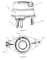
- the figure 1 present in a three-dimensional view a device according to a preferred embodiment of the invention.
- the figure 2 shows a view of a detail of a device according to a preferred embodiment of the invention.
- FIG 3 according to a three-dimensional view of a first point of view, an indexing means as implemented in a preferred variant of the invention.
- the figure 4 presents according to a second point of view an indexing means as implemented in a preferred variant of the invention.
- FIG. 1 there is shown in a three-dimensional view a device according to a preferred embodiment of the invention.
- a device comprises a fuel pump 1.
- the fuel pump 1 is arranged to be rotated by a gear wheel 11.
- the angular position, the "setting" of the pump 1 and therefore of its drive gear 11 must be perfectly controlled to be wedged with respect to the operating cycle of the engine (typically hold the pump in relation to a bottom dead center of the engine).
- an indexing means 2 is arranged so as to immobilize the toothed wheel (and therefore the pump) in a predefined position.
- the indexing means may comprise a tooth 23 meshing with the toothed wheel.
- the indexing means is preferably a plug having an internal shape complementary to the toothed wheel 11, that is to say a shape with respect to which the teeth of the toothed wheel 11 are immobilized in rotation.
- an opening 21 may be provided in the indexing means in order to be able to match a mark 12 carried by the toothed wheel 11 with a mark 22 which the indexing means 2 comprises.
- the indexing means 2 In order to maintain the indexing means 2 on the body of the fuel pump 1, it is preferably provided with one or more extensions 24, 24 '.
- the extensions 24, 24 ' preferably have a radial elasticity, and tend to move away when they are inserted into orifices of the pump body.
- the extensions 24, 24 ' are shaped to be introduced into the bores provided to receive fixing screws of the fuel pump 1 on a motor.
- the fastening means involved can therefore be, as presented in figure 3 , split ends longitudinally to give them a radial elasticity.
- the figure 4 according to a second point of view the indexing means 2 presented in figure 3 .
- the indexing means 2 is here seen “from below”, that is to say showing the cavity in which the toothed wheel of the fuel pump 1 will be inserted.
- the invention thus provides a device for ensuring compliance with the position of the pinion from the end of the assembly at the supplier until the beginning of assembly in engine assembly plant.
- the gear wheel of the pump is properly phased with respect to its synchronous drive structure connected to the crankshaft of the engine, and this to the tooth near. In the end, this ensures, by limiting the torques suffered, a good mechanical strength of the entire drive system, including the belt it may contain.
Landscapes
- Engineering & Computer Science (AREA)
- Mechanical Engineering (AREA)
- Chemical & Material Sciences (AREA)
- Combustion & Propulsion (AREA)
- General Engineering & Computer Science (AREA)
- Rotary Pumps (AREA)
- Fuel-Injection Apparatus (AREA)
Abstract
● une pompe à carburant (1) pour moteur à combustion, comportant une roue dentée (11) pour son entraînement,
● un moyen d'indexation (2), immobilisant la roue dentée (11) dans une position donnée par rapport à un corps de la pompe.
Description
- L'invention porte sur le domaine des moteurs à combustion. Elle porte plus précisément sur les moteurs à combustion comportant une pompe haute pression pour l'alimentation et la mise en pression d'un système d'injection de carburant.
- Les moteurs à combustion, et notamment les moteurs dit à injection directe, c'est-à-dire comportant des injecteurs de carburant débouchant directement dans les chambres de combustion, comportent une pompe à carburant dite « pompe haute pression » permettant de mettre et maintenir en pression le carburant dans une rampe d'alimentation des injecteurs. Bien que plus fréquente sur les moteur de type Diesel, cette technologie peut également concerner les moteurs à allumage commandé (généralement appelés moteurs à essence).
- La pompe à haute pression est entrainée mécaniquement par le moteur qu'elle alimente. En pratique, la pompe à haute pression présente un arbre d'entrée, dont la rotation actionne un moyen de pompage, typiquement un piston mobile dans un cylindre.
- L'arbre de la pompe est doté d'une roue dentée pour son entraînement. La mise en rotation de la roue dentée, et donc de l'arbre d'entrée de la pompe peut être assuré par une autre roue dentée, ou, plus communément par une courroie ou une chaîne. Cette courroie ou chaîne est typiquement celle de distribution du moteur, reliant un vilebrequin du moteur à l'arbre à cames (ou aux arbres à cames) actionnant les soupapes.
- Un mauvais calage de la pompe haute pression par rapport au vilebrequin induit dans l'ensemble du système des efforts fluctuants dans la courroie se traduisant par des couples induits au niveau des poulies, ce qui est néfaste à la fiabilité dans le temps du système. Généralement, aucun dispositif particulier assurant un calage ou une indexation précise de la pompe haute pression par rapport au vilebrequin du moteur n'est nécessaire, car la pompe est bien souvent entrainée directement par le vilebrequin, de sorte qu'il n'y a pas de structure de transmission (courroie, chaîne, etc.) dans laquelle elle génère des fluctuations. Mais, lorsque la pompe est entrainée via une telle structure de transmission, les fluctuations générées peuvent entraîner une rupture de courroie de distribution, potentiellement destructrice du moteur, ou l'endommagement des paliers ou roulement d'arbres (arbre de pompe, vilebrequin, arbre à came) engendrant un risque de défaillance ou la génération de bruits et vibrations.
- En outre, un bon calage entre la pompe haute pression et le moteur est nécessaire pour que les efforts générés par la pompe ne perturbent pas le moteur lors de son démarrage, et, en particulier, il est nécessaire d'avoir un calage optimal pour permettre le démarrage systématique du moteur dans un temps réduit, typiquement en deux points mort hauts du cycle du moteur pour un moteur à 4 cylindres. Cela est fondamental pour les applications automobiles dotées d'un système d'arrêt et redémarrage automatique du moteur (système bien connu sous l'expression anglophone « stop and start »).
- Il convient donc de concevoir un moyen permettant d'assurer que la pompe est montée, typiquement en usine de montage des moteurs, avec un calage adéquat vis-à-vis du moteur qu'elle équipe. L'invention tend à résoudre cette problématique par un moyen simple.
- Plus précisément, l'invention porte donc sur un dispositif comportant
- une pompe à carburant pour moteur à combustion, comportant une roue dentée pour son entraînement,
- un moyen d'indexation, immobilisant la roue dentée dans une position donnée par rapport à un corps de la pompe.
- L'invention permet ainsi le transport et la manutention d'une pompe à carburant dans une position donnée de son cycle de fonctionnement, ce qui permet de la monter sur un moteur présentant lui-même une position prédéfinie dans son cycle afin de garantir le calage souhaité entre la pompe à carburant et le moteur.
- De préférence, le moyen d'indexation comporte un bouchon de forme interne comportant au moins une dent s'engrenant avec la roue dentée pour la bloquer en rotation vis-à-vis du moyen d'indexation.
- De préférence, la roue dentée comporte une marque destinée à être mise en regard d'un repère que comporte le moyen d'indexation. Cette mise en correspondance assure et garantit un calage donné de la pompe dans son cycle.
- De préférence, le moyen d'indexation comporte un moyen de fixation sur le corps de la pompe. Le moyen de fixation peut comporter une ou plusieurs extensions insérées dans des orifices que comporte le corps de la pompe. De préférence, ces extensions présentent une élasticité radiale de sorte à être maintenues sur la pompe à carburant sous l'effet de cette élasticité.
- Selon un mode de réalisation préférentiel de l'invention, chaque extension est insérée dans un orifice de la pompe à carburant destiné à recevoir une vis de montage de la pompe à carburant sur un moteur.
- L'invention porte aussi sur un procédé de montage d'une pompe à carburant sur un moteur à combustion, caractérisé par les étapes de :
- Fourniture d'un dispositif tel que précédemment décrit ;
- Retrait du moyen d'indexation ;
- Assemblage de la pompe à carburant sur le moteur et de moyens d'entrainements synchrones de la roue dentée.
- Selon le mode de réalisation de l'invention, ces deux dernières étapes du procédé peuvent être interverties (le retrait du moyen d'indexation devant précéder nécessairement l'assemblage de la pompe seulement si les moyens de fixation de la pompe sur le moteur, typiquement les alésages dans lesquels on positionne des vis de fixation, sont masqués par le moyen d'indexation, par exemple par les moyens de fixation du moyen d'indexations sur le corps de la pompe.
- L'invention est décrite plus en détail ci-après et en référence aux figures représentant schématiquement le système dans son mode de réalisation préférentiel.
- La
figure 1 présente selon une vue en trois dimensions un dispositif conforme à une variante préférentielle de l'invention. - La
figure 2 présente une vue d'un détail d'un dispositif conforme à une variante préférentielle de l'invention. - La
figure 3 présente selon une vue en trois dimensions d'un premier point de vue un moyen d'indexation tel que mis en jeu dans une variante préférentielle de l'invention. - La
figure 4 présente selon un second point de vue un moyen d'indexation tel que mis en jeu dans une variante préférentielle de l'invention. - A la
figure 1 on a représenté selon une vue en trois dimensions un dispositif conforme à une variante préférentielle de l'invention. Un tel dispositif comprend une pompe à carburant 1. La pompe à carburant 1 est arrangée pour être entrainée en rotation par une roue dentée 11. Lors du montage de pompe sur un moteur, et de sa liaison avec un vilebrequin du moteur à l'aide d'un dispositif d'entrainement synchrone, la position angulaire, le « calage » de la pompe 1 et donc de sa roue dentée 11 d'entraînement doit être parfaitement maîtrisé pour être calé par rapport au cycle de fonctionnement du moteur (typiquement, on cale la pompe par rapport à un point mort bas du moteur). - Dans l'invention, un moyen d'indexation 2 est disposé de sorte à immobiliser la roue dentée (et donc la pompe) dans une position prédéfinie. Pour ce faire, le moyen d'indexation peut comporter une dent 23 s'engrenant avec la roue dentée.
- Pour ce faire, le moyen d'indexation est préférentiellement un bouchon présentant une forme interne complémentaire de la roue dentée 11, c'est-à-dire une forme par rapport à laquelle les dents de la roue dentée 11 sont immobilisées en rotation.
- Tel que présenté en détail à la
figure 2 , une ouverture 21 peut être ménagée dans le moyen d'indexation afin de pouvoir mettre en correspondance une marque 12 portée par la roue dentée 11 avec un repère 22 que comporte le moyen d'indexation 2. - Afin de maintenir le moyen d'indexation 2 sur le corps de la pompe à carburant 1, on le dote préférentiellement d'une ou plusieurs extensions 24, 24'. Les extensions 24, 24' présentent préférentiellement une élasticité radiale, et tendent à s'écarter lorsqu'elles sont insérées dans des orifices du corps de pompe. Préférentiellement, les extensions 24, 24' sont conformées pour être introduites dans les alésages prévus pour recevoir des vis de fixation de la pompe à carburant 1 sur un moteur. Les moyens de fixations mis en jeu peuvent donc être, comme présenté en
figure 3 , des plots fendus longitudinalement pour leur conférer une élasticité radiale. - La
figure 4 présente selon un second point de vue le moyen d'indexation 2 présenté enfigure 3 . Le moyen d'indexation 2 est ici vu « de dessous », c'est-à-dire montrant la cavité dans laquelle la roue dentée de la pompe à carburant 1 sera insérée. - L'invention propose ainsi un dispositif permettant d'assurer le respect de la position du pignon à partir de la fin de l'assemblage chez le fournisseur jusqu'au début de l'assemblage en usine de montage de moteurs. Ainsi, la roue dentée de la pompe est correctement phasée par rapport à sa structure d'entrainement synchrone liée au vilebrequin du moteur, et ce à la dent près. Au final, ceci assure, par la limitation des couples subis, une bonne tenue mécanique de l'ensemble du système d'entrainement, notamment de la courroie qu'il peut comporter.
Claims (8)
- Dispositif comportant• une pompe à carburant (1) pour moteur à combustion, comportant une roue dentée (11) pour son entraînement,• un moyen d'indexation (2), immobilisant la roue dentée (11) dans une position donnée par rapport à un corps de la pompe.
- Dispositif selon la revendication 1, dans lequel le moyen d'indexation (2) comporte un bouchon de forme interne comportant au moins une dent (23) s'engrenant avec la roue dentée (11) pour la bloquer en rotation vis-à-vis du moyen d'indexation (2).
- Dispositif selon la revendication 1 ou la revendication 2, dans lequel la roue dentée (11) comporte une marque (12) destinée à être mise en regard d'un repère (22) que comporte le moyen d'indexation (2).
- Dispositif selon l'une des revendications précédentes, dans lequel le moyen d'indexation (2) comporte un moyen de fixation sur le corps de la pompe.
- Dispositif selon la revendication 4, dans lequel le moyen de fixation comporte une ou plusieurs extensions (24,24') insérées dans des orifices que comporte le corps de la pompe.
- Dispositif selon la revendication 5, les extensions (24, 24') présentant une élasticité radiale de sorte à être maintenues sur la pompe à carburant (1) sous l'effet de cette élasticité.
- Dispositif selon la revendication 5 ou la revendication 6, dans lequel chaque extension (24, 24') est insérée dans un orifice de la pompe à carburant destiné à recevoir une vis de montage de la pompe à carburant (1) sur un moteur.
- Procédé de montage d'une pompe à carburant sur un moteur à combustion, caractérisé par les étapes de :• Fourniture d'un dispositif selon l'une des revendications précédentes ;• Retrait du moyen d'indexation (2) ;• Assemblage de la pompe à carburant (1) sur le moteur et de moyens d'entrainements synchrones de la roue dentée.
Applications Claiming Priority (1)
| Application Number | Priority Date | Filing Date | Title |
|---|---|---|---|
| FR1254748A FR2991000A1 (fr) | 2012-05-24 | 2012-05-24 | Dispositif comportant une pompe a carburant et un moyen d'indexation |
Publications (2)
| Publication Number | Publication Date |
|---|---|
| EP2666593A1 true EP2666593A1 (fr) | 2013-11-27 |
| EP2666593B1 EP2666593B1 (fr) | 2016-04-06 |
Family
ID=48095750
Family Applications (1)
| Application Number | Title | Priority Date | Filing Date |
|---|---|---|---|
| EP13164589.7A Active EP2666593B1 (fr) | 2012-05-24 | 2013-04-19 | Dispositif comportant une pompe à carburant et un moyen d'indexation |
Country Status (2)
| Country | Link |
|---|---|
| EP (1) | EP2666593B1 (fr) |
| FR (1) | FR2991000A1 (fr) |
Families Citing this family (1)
| Publication number | Priority date | Publication date | Assignee | Title |
|---|---|---|---|---|
| FR3072725B1 (fr) * | 2017-10-20 | 2022-05-06 | Renault Sas | Dent longue usinee sur pignon pompe haute pression |
Citations (7)
| Publication number | Priority date | Publication date | Assignee | Title |
|---|---|---|---|---|
| US4123835A (en) * | 1976-08-06 | 1978-11-07 | Nippondenso Co., Ltd. | Method for assembling a fuel pump to an internal combustion engine |
| US4322174A (en) * | 1978-02-24 | 1982-03-30 | Nippondenso Co., Ltd. | Cam shaft locking device for fuel injection pump |
| JPS5781043U (fr) * | 1980-10-31 | 1982-05-19 | ||
| JPH0777134A (ja) * | 1993-09-10 | 1995-03-20 | Nippondenso Co Ltd | 燃料噴射ポンプの駆動軸固定装置 |
| EP1431572A1 (fr) * | 2002-12-18 | 2004-06-23 | Peugeot Citroen Automobiles | Moteur à combustion interne muni d'une pompe et procédé de remplacement de ladite pompe |
| EP2088308A1 (fr) * | 2008-02-08 | 2009-08-12 | Perkins Engines Company Limited | Positionnement de deux éléments rotatifs l'un par rapport à l'autre |
| DE102008021268A1 (de) * | 2008-04-29 | 2009-11-12 | GM Global Technology Operations, Inc., Detroit | Montagehilfe |
-
2012
- 2012-05-24 FR FR1254748A patent/FR2991000A1/fr active Pending
-
2013
- 2013-04-19 EP EP13164589.7A patent/EP2666593B1/fr active Active
Patent Citations (7)
| Publication number | Priority date | Publication date | Assignee | Title |
|---|---|---|---|---|
| US4123835A (en) * | 1976-08-06 | 1978-11-07 | Nippondenso Co., Ltd. | Method for assembling a fuel pump to an internal combustion engine |
| US4322174A (en) * | 1978-02-24 | 1982-03-30 | Nippondenso Co., Ltd. | Cam shaft locking device for fuel injection pump |
| JPS5781043U (fr) * | 1980-10-31 | 1982-05-19 | ||
| JPH0777134A (ja) * | 1993-09-10 | 1995-03-20 | Nippondenso Co Ltd | 燃料噴射ポンプの駆動軸固定装置 |
| EP1431572A1 (fr) * | 2002-12-18 | 2004-06-23 | Peugeot Citroen Automobiles | Moteur à combustion interne muni d'une pompe et procédé de remplacement de ladite pompe |
| EP2088308A1 (fr) * | 2008-02-08 | 2009-08-12 | Perkins Engines Company Limited | Positionnement de deux éléments rotatifs l'un par rapport à l'autre |
| DE102008021268A1 (de) * | 2008-04-29 | 2009-11-12 | GM Global Technology Operations, Inc., Detroit | Montagehilfe |
Also Published As
| Publication number | Publication date |
|---|---|
| FR2991000A1 (fr) | 2013-11-29 |
| EP2666593B1 (fr) | 2016-04-06 |
Similar Documents
| Publication | Publication Date | Title |
|---|---|---|
| EP2666593B1 (fr) | Dispositif comportant une pompe à carburant et un moyen d'indexation | |
| FR2988771A1 (fr) | Dispositif pour la desactivation partielle des cylindres d'un moteur a combustion interne | |
| FR2786819A1 (fr) | Pompe a piston radiaux | |
| EP1886760B1 (fr) | Procédé de positionnement et de montage dans la culasse d'un moteur de véhicule d'au moins un arbre a cames sur roulements, et dispositif pour la mise en oeuvre d'un tel procédé | |
| FR2866059A1 (fr) | Dispositif et procede de reglage angulaire d'un vilebrequin de moteur a combustion interne | |
| US7743749B1 (en) | Fuel pump drive system | |
| FR2989121A1 (fr) | Pompe a carburant comportant un moyen d'indexation entre un arbre d'entree et une roue d'entrainement | |
| WO2019092085A1 (fr) | Procede de calage pompe haute pression / vilebrequin | |
| EP1431572B1 (fr) | Moteur à combustion interne muni d'une pompe et procédé de remplacement de ladite pompe | |
| EP1375861A1 (fr) | Positionnement de vilebrequin | |
| WO2005019634A3 (fr) | Mecanisme de decompression automatique comprenant une fonction empechant toute desactivation involontaire pendant l'arret du moteur | |
| KR200452129Y1 (ko) | 연료펌프의 구동기어부 탈착 보조장치 및 이를 이용한 구동기어부 장착방법 | |
| FR3091915A1 (fr) | « Pièce métallique pour un moteur à combustion interne et ensemble comportant une telle pièce » | |
| FR3042567A1 (fr) | Boucle de transmission avec chaine comportant un maillon distinctif | |
| KR100739444B1 (ko) | 자동차용 엔진의 고압펌프 | |
| EP3332138B1 (fr) | Moteur a combustion, aeronef equipe dudit moteur et procede de fabrication d'un tel moteur | |
| FR3013772A1 (fr) | Carter de distribution integrant une pompe a vide entrainee par une courroie d'entrainement de la facade accessoire d'un carter cylindres | |
| JPH05179997A (ja) | 燃料噴射ポンプの進角調整方法 | |
| WO2025133528A1 (fr) | Turbomachine comprenant plusieurs modules et un dispositif de blocage de ces modules, et procede de montage correspondant | |
| JPH09152016A (ja) | シザースギヤの位相合わせ用治具 | |
| CN102032005B (zh) | 凸轮链轮的连结组件 | |
| FR3001266A1 (fr) | Systeme d'accouplement mecanique | |
| FR3013406A1 (fr) | Agencement d'accouplement mecanique d'une piece d'entrainement a une piece a entrainer, pompe d'essence d'un vehicule automobile ainsi que vehicule automobile, comportant un tel agencement | |
| FR3107306A1 (fr) | Système d’assistance électrique d’un moteur à combustion | |
| FR3072725A1 (fr) | Dent longue usinee sur pignon pompe haute pression |
Legal Events
| Date | Code | Title | Description |
|---|---|---|---|
| PUAI | Public reference made under article 153(3) epc to a published international application that has entered the european phase |
Free format text: ORIGINAL CODE: 0009012 |
|
| AK | Designated contracting states |
Kind code of ref document: A1 Designated state(s): AL AT BE BG CH CY CZ DE DK EE ES FI FR GB GR HR HU IE IS IT LI LT LU LV MC MK MT NL NO PL PT RO RS SE SI SK SM TR |
|
| AX | Request for extension of the european patent |
Extension state: BA ME |
|
| 17P | Request for examination filed |
Effective date: 20140328 |
|
| RBV | Designated contracting states (corrected) |
Designated state(s): AL AT BE BG CH CY CZ DE DK EE ES FI FR GB GR HR HU IE IS IT LI LT LU LV MC MK MT NL NO PL PT RO RS SE SI SK SM TR |
|
| 17Q | First examination report despatched |
Effective date: 20141113 |
|
| REG | Reference to a national code |
Ref country code: DE Ref legal event code: R079 Ref document number: 602013006080 Country of ref document: DE Free format text: PREVIOUS MAIN CLASS: B25B0027000000 Ipc: F02M0059480000 |
|
| GRAP | Despatch of communication of intention to grant a patent |
Free format text: ORIGINAL CODE: EPIDOSNIGR1 |
|
| RIC1 | Information provided on ipc code assigned before grant |
Ipc: F02M 59/44 20060101ALI20151112BHEP Ipc: B25B 27/00 20060101ALI20151112BHEP Ipc: F02M 59/48 20060101AFI20151112BHEP Ipc: F02M 39/00 20060101ALI20151112BHEP |
|
| INTG | Intention to grant announced |
Effective date: 20151209 |
|
| GRAS | Grant fee paid |
Free format text: ORIGINAL CODE: EPIDOSNIGR3 |
|
| GRAA | (expected) grant |
Free format text: ORIGINAL CODE: 0009210 |
|
| AK | Designated contracting states |
Kind code of ref document: B1 Designated state(s): AL AT BE BG CH CY CZ DE DK EE ES FI FR GB GR HR HU IE IS IT LI LT LU LV MC MK MT NL NO PL PT RO RS SE SI SK SM TR |
|
| REG | Reference to a national code |
Ref country code: GB Ref legal event code: FG4D Free format text: NOT ENGLISH |
|
| REG | Reference to a national code |
Ref country code: AT Ref legal event code: REF Ref document number: 788114 Country of ref document: AT Kind code of ref document: T Effective date: 20160415 Ref country code: CH Ref legal event code: EP |
|
| REG | Reference to a national code |
Ref country code: IE Ref legal event code: FG4D Free format text: LANGUAGE OF EP DOCUMENT: FRENCH |
|
| REG | Reference to a national code |
Ref country code: DE Ref legal event code: R096 Ref document number: 602013006080 Country of ref document: DE |
|
| REG | Reference to a national code |
Ref country code: FR Ref legal event code: PLFP Year of fee payment: 4 |
|
| REG | Reference to a national code |
Ref country code: LT Ref legal event code: MG4D Ref country code: NL Ref legal event code: MP Effective date: 20160406 |
|
| REG | Reference to a national code |
Ref country code: AT Ref legal event code: MK05 Ref document number: 788114 Country of ref document: AT Kind code of ref document: T Effective date: 20160406 |
|
| PG25 | Lapsed in a contracting state [announced via postgrant information from national office to epo] |
Ref country code: BE Free format text: LAPSE BECAUSE OF NON-PAYMENT OF DUE FEES Effective date: 20160430 |
|
| PG25 | Lapsed in a contracting state [announced via postgrant information from national office to epo] |
Ref country code: NL Free format text: LAPSE BECAUSE OF FAILURE TO SUBMIT A TRANSLATION OF THE DESCRIPTION OR TO PAY THE FEE WITHIN THE PRESCRIBED TIME-LIMIT Effective date: 20160406 |
|
| REG | Reference to a national code |
Ref country code: DE Ref legal event code: R084 Ref document number: 602013006080 Country of ref document: DE |
|
| PG25 | Lapsed in a contracting state [announced via postgrant information from national office to epo] |
Ref country code: FI Free format text: LAPSE BECAUSE OF FAILURE TO SUBMIT A TRANSLATION OF THE DESCRIPTION OR TO PAY THE FEE WITHIN THE PRESCRIBED TIME-LIMIT Effective date: 20160406 Ref country code: IS Free format text: LAPSE BECAUSE OF FAILURE TO SUBMIT A TRANSLATION OF THE DESCRIPTION OR TO PAY THE FEE WITHIN THE PRESCRIBED TIME-LIMIT Effective date: 20160806 Ref country code: PL Free format text: LAPSE BECAUSE OF FAILURE TO SUBMIT A TRANSLATION OF THE DESCRIPTION OR TO PAY THE FEE WITHIN THE PRESCRIBED TIME-LIMIT Effective date: 20160406 Ref country code: LT Free format text: LAPSE BECAUSE OF FAILURE TO SUBMIT A TRANSLATION OF THE DESCRIPTION OR TO PAY THE FEE WITHIN THE PRESCRIBED TIME-LIMIT Effective date: 20160406 Ref country code: NO Free format text: LAPSE BECAUSE OF FAILURE TO SUBMIT A TRANSLATION OF THE DESCRIPTION OR TO PAY THE FEE WITHIN THE PRESCRIBED TIME-LIMIT Effective date: 20160706 |
|
| REG | Reference to a national code |
Ref country code: GB Ref legal event code: 746 Effective date: 20161012 |
|
| PG25 | Lapsed in a contracting state [announced via postgrant information from national office to epo] |
Ref country code: AT Free format text: LAPSE BECAUSE OF FAILURE TO SUBMIT A TRANSLATION OF THE DESCRIPTION OR TO PAY THE FEE WITHIN THE PRESCRIBED TIME-LIMIT Effective date: 20160406 Ref country code: GR Free format text: LAPSE BECAUSE OF FAILURE TO SUBMIT A TRANSLATION OF THE DESCRIPTION OR TO PAY THE FEE WITHIN THE PRESCRIBED TIME-LIMIT Effective date: 20160707 Ref country code: PT Free format text: LAPSE BECAUSE OF FAILURE TO SUBMIT A TRANSLATION OF THE DESCRIPTION OR TO PAY THE FEE WITHIN THE PRESCRIBED TIME-LIMIT Effective date: 20160808 Ref country code: ES Free format text: LAPSE BECAUSE OF FAILURE TO SUBMIT A TRANSLATION OF THE DESCRIPTION OR TO PAY THE FEE WITHIN THE PRESCRIBED TIME-LIMIT Effective date: 20160406 Ref country code: LV Free format text: LAPSE BECAUSE OF FAILURE TO SUBMIT A TRANSLATION OF THE DESCRIPTION OR TO PAY THE FEE WITHIN THE PRESCRIBED TIME-LIMIT Effective date: 20160406 Ref country code: RS Free format text: LAPSE BECAUSE OF FAILURE TO SUBMIT A TRANSLATION OF THE DESCRIPTION OR TO PAY THE FEE WITHIN THE PRESCRIBED TIME-LIMIT Effective date: 20160406 Ref country code: HR Free format text: LAPSE BECAUSE OF FAILURE TO SUBMIT A TRANSLATION OF THE DESCRIPTION OR TO PAY THE FEE WITHIN THE PRESCRIBED TIME-LIMIT Effective date: 20160406 Ref country code: SE Free format text: LAPSE BECAUSE OF FAILURE TO SUBMIT A TRANSLATION OF THE DESCRIPTION OR TO PAY THE FEE WITHIN THE PRESCRIBED TIME-LIMIT Effective date: 20160406 |
|
| REG | Reference to a national code |
Ref country code: CH Ref legal event code: PL |
|
| PG25 | Lapsed in a contracting state [announced via postgrant information from national office to epo] |
Ref country code: IT Free format text: LAPSE BECAUSE OF FAILURE TO SUBMIT A TRANSLATION OF THE DESCRIPTION OR TO PAY THE FEE WITHIN THE PRESCRIBED TIME-LIMIT Effective date: 20160406 |
|
| REG | Reference to a national code |
Ref country code: DE Ref legal event code: R097 Ref document number: 602013006080 Country of ref document: DE |
|
| REG | Reference to a national code |
Ref country code: IE Ref legal event code: MM4A |
|
| PG25 | Lapsed in a contracting state [announced via postgrant information from national office to epo] |
Ref country code: SK Free format text: LAPSE BECAUSE OF FAILURE TO SUBMIT A TRANSLATION OF THE DESCRIPTION OR TO PAY THE FEE WITHIN THE PRESCRIBED TIME-LIMIT Effective date: 20160406 Ref country code: RO Free format text: LAPSE BECAUSE OF FAILURE TO SUBMIT A TRANSLATION OF THE DESCRIPTION OR TO PAY THE FEE WITHIN THE PRESCRIBED TIME-LIMIT Effective date: 20160406 Ref country code: CZ Free format text: LAPSE BECAUSE OF FAILURE TO SUBMIT A TRANSLATION OF THE DESCRIPTION OR TO PAY THE FEE WITHIN THE PRESCRIBED TIME-LIMIT Effective date: 20160406 Ref country code: LI Free format text: LAPSE BECAUSE OF NON-PAYMENT OF DUE FEES Effective date: 20160430 Ref country code: EE Free format text: LAPSE BECAUSE OF FAILURE TO SUBMIT A TRANSLATION OF THE DESCRIPTION OR TO PAY THE FEE WITHIN THE PRESCRIBED TIME-LIMIT Effective date: 20160406 Ref country code: MC Free format text: LAPSE BECAUSE OF FAILURE TO SUBMIT A TRANSLATION OF THE DESCRIPTION OR TO PAY THE FEE WITHIN THE PRESCRIBED TIME-LIMIT Effective date: 20160406 Ref country code: CH Free format text: LAPSE BECAUSE OF NON-PAYMENT OF DUE FEES Effective date: 20160430 Ref country code: DK Free format text: LAPSE BECAUSE OF FAILURE TO SUBMIT A TRANSLATION OF THE DESCRIPTION OR TO PAY THE FEE WITHIN THE PRESCRIBED TIME-LIMIT Effective date: 20160406 |
|
| PLBE | No opposition filed within time limit |
Free format text: ORIGINAL CODE: 0009261 |
|
| STAA | Information on the status of an ep patent application or granted ep patent |
Free format text: STATUS: NO OPPOSITION FILED WITHIN TIME LIMIT |
|
| PG25 | Lapsed in a contracting state [announced via postgrant information from national office to epo] |
Ref country code: SM Free format text: LAPSE BECAUSE OF FAILURE TO SUBMIT A TRANSLATION OF THE DESCRIPTION OR TO PAY THE FEE WITHIN THE PRESCRIBED TIME-LIMIT Effective date: 20160406 |
|
| 26N | No opposition filed |
Effective date: 20170110 |
|
| REG | Reference to a national code |
Ref country code: FR Ref legal event code: PLFP Year of fee payment: 5 |
|
| PG25 | Lapsed in a contracting state [announced via postgrant information from national office to epo] |
Ref country code: SI Free format text: LAPSE BECAUSE OF FAILURE TO SUBMIT A TRANSLATION OF THE DESCRIPTION OR TO PAY THE FEE WITHIN THE PRESCRIBED TIME-LIMIT Effective date: 20160406 Ref country code: IE Free format text: LAPSE BECAUSE OF NON-PAYMENT OF DUE FEES Effective date: 20160419 |
|
| REG | Reference to a national code |
Ref country code: FR Ref legal event code: PLFP Year of fee payment: 6 |
|
| PG25 | Lapsed in a contracting state [announced via postgrant information from national office to epo] |
Ref country code: CY Free format text: LAPSE BECAUSE OF FAILURE TO SUBMIT A TRANSLATION OF THE DESCRIPTION OR TO PAY THE FEE WITHIN THE PRESCRIBED TIME-LIMIT Effective date: 20160406 Ref country code: HU Free format text: LAPSE BECAUSE OF FAILURE TO SUBMIT A TRANSLATION OF THE DESCRIPTION OR TO PAY THE FEE WITHIN THE PRESCRIBED TIME-LIMIT; INVALID AB INITIO Effective date: 20130419 |
|
| PG25 | Lapsed in a contracting state [announced via postgrant information from national office to epo] |
Ref country code: MK Free format text: LAPSE BECAUSE OF FAILURE TO SUBMIT A TRANSLATION OF THE DESCRIPTION OR TO PAY THE FEE WITHIN THE PRESCRIBED TIME-LIMIT Effective date: 20160406 Ref country code: LU Free format text: LAPSE BECAUSE OF NON-PAYMENT OF DUE FEES Effective date: 20160419 Ref country code: TR Free format text: LAPSE BECAUSE OF FAILURE TO SUBMIT A TRANSLATION OF THE DESCRIPTION OR TO PAY THE FEE WITHIN THE PRESCRIBED TIME-LIMIT Effective date: 20160406 Ref country code: MT Free format text: LAPSE BECAUSE OF FAILURE TO SUBMIT A TRANSLATION OF THE DESCRIPTION OR TO PAY THE FEE WITHIN THE PRESCRIBED TIME-LIMIT Effective date: 20160406 |
|
| REG | Reference to a national code |
Ref country code: FR Ref legal event code: CA Effective date: 20180312 Ref country code: FR Ref legal event code: CD Owner name: PEUGEOT CITROEN AUTOMOBILES SA, FR Effective date: 20180312 |
|
| PG25 | Lapsed in a contracting state [announced via postgrant information from national office to epo] |
Ref country code: BG Free format text: LAPSE BECAUSE OF FAILURE TO SUBMIT A TRANSLATION OF THE DESCRIPTION OR TO PAY THE FEE WITHIN THE PRESCRIBED TIME-LIMIT Effective date: 20160406 |
|
| PG25 | Lapsed in a contracting state [announced via postgrant information from national office to epo] |
Ref country code: AL Free format text: LAPSE BECAUSE OF FAILURE TO SUBMIT A TRANSLATION OF THE DESCRIPTION OR TO PAY THE FEE WITHIN THE PRESCRIBED TIME-LIMIT Effective date: 20160406 |
|
| PGFP | Annual fee paid to national office [announced via postgrant information from national office to epo] |
Ref country code: GB Payment date: 20240320 Year of fee payment: 12 |
|
| PGFP | Annual fee paid to national office [announced via postgrant information from national office to epo] |
Ref country code: DE Payment date: 20240320 Year of fee payment: 12 |
|
| REG | Reference to a national code |
Ref country code: DE Ref legal event code: R119 Ref document number: 602013006080 Country of ref document: DE |
|
| GBPC | Gb: european patent ceased through non-payment of renewal fee |
Effective date: 20250419 |
|
| PG25 | Lapsed in a contracting state [announced via postgrant information from national office to epo] |
Ref country code: DE Free format text: LAPSE BECAUSE OF NON-PAYMENT OF DUE FEES Effective date: 20251104 |
|
| PG25 | Lapsed in a contracting state [announced via postgrant information from national office to epo] |
Ref country code: GB Free format text: LAPSE BECAUSE OF NON-PAYMENT OF DUE FEES Effective date: 20250419 |
|
| PGFP | Annual fee paid to national office [announced via postgrant information from national office to epo] |
Ref country code: FR Payment date: 20260320 Year of fee payment: 14 |