EP2665941B1 - Spanplattenschraube - Google Patents
Spanplattenschraube Download PDFInfo
- Publication number
- EP2665941B1 EP2665941B1 EP12700679.9A EP12700679A EP2665941B1 EP 2665941 B1 EP2665941 B1 EP 2665941B1 EP 12700679 A EP12700679 A EP 12700679A EP 2665941 B1 EP2665941 B1 EP 2665941B1
- Authority
- EP
- European Patent Office
- Prior art keywords
- screw
- scraper
- ribs
- particle board
- scraper ribs
- Prior art date
- Legal status (The legal status is an assumption and is not a legal conclusion. Google has not performed a legal analysis and makes no representation as to the accuracy of the status listed.)
- Revoked
Links
- 239000011093 chipboard Substances 0.000 claims description 7
- 239000002245 particle Substances 0.000 claims 9
- 230000007704 transition Effects 0.000 claims 1
- 238000011161 development Methods 0.000 description 4
- 230000018109 developmental process Effects 0.000 description 4
- 239000002023 wood Substances 0.000 description 3
- 239000000463 material Substances 0.000 description 2
- 230000001419 dependent effect Effects 0.000 description 1
- 230000000694 effects Effects 0.000 description 1
- 238000004804 winding Methods 0.000 description 1
Images
Classifications
-
- F—MECHANICAL ENGINEERING; LIGHTING; HEATING; WEAPONS; BLASTING
- F16—ENGINEERING ELEMENTS AND UNITS; GENERAL MEASURES FOR PRODUCING AND MAINTAINING EFFECTIVE FUNCTIONING OF MACHINES OR INSTALLATIONS; THERMAL INSULATION IN GENERAL
- F16B—DEVICES FOR FASTENING OR SECURING CONSTRUCTIONAL ELEMENTS OR MACHINE PARTS TOGETHER, e.g. NAILS, BOLTS, CIRCLIPS, CLAMPS, CLIPS OR WEDGES; JOINTS OR JOINTING
- F16B25/00—Screws that cut thread in the body into which they are screwed, e.g. wood screws
- F16B25/001—Screws that cut thread in the body into which they are screwed, e.g. wood screws characterised by the material of the body into which the screw is screwed
- F16B25/0015—Screws that cut thread in the body into which they are screwed, e.g. wood screws characterised by the material of the body into which the screw is screwed the material being a soft organic material, e.g. wood or plastic
-
- F—MECHANICAL ENGINEERING; LIGHTING; HEATING; WEAPONS; BLASTING
- F16—ENGINEERING ELEMENTS AND UNITS; GENERAL MEASURES FOR PRODUCING AND MAINTAINING EFFECTIVE FUNCTIONING OF MACHINES OR INSTALLATIONS; THERMAL INSULATION IN GENERAL
- F16B—DEVICES FOR FASTENING OR SECURING CONSTRUCTIONAL ELEMENTS OR MACHINE PARTS TOGETHER, e.g. NAILS, BOLTS, CIRCLIPS, CLAMPS, CLIPS OR WEDGES; JOINTS OR JOINTING
- F16B25/00—Screws that cut thread in the body into which they are screwed, e.g. wood screws
- F16B25/0036—Screws that cut thread in the body into which they are screwed, e.g. wood screws characterised by geometric details of the screw
- F16B25/0078—Screws that cut thread in the body into which they are screwed, e.g. wood screws characterised by geometric details of the screw with a shaft of non-circular cross-section or other special geometric features of the shaft
Definitions
- the invention relates to a chipboard screw.
- chipboard screws have a thread that is adapted to the use of this type of screws for screwing into chipboard. Of course they can also be used for fixing in wood.
- a wood screw which has two radial projections between two adjacent turns.
- the projections either form edges or are rounded ( US 2003/0231940 A1 ).
- the invention is based on the object to provide a chipboard screw, which achieves an improved screwing and a lower splitting effect when used with wood or wood-like material, but which is also suitable for dowel fittings.
- the invention proposes a chipboard screw with the features mentioned in claim 1. Further developments of the invention are the subject of dependent claims.
- the beginning of the scraper ribs is arranged at the point where the conical tip of the screw merges into the cylindrical screw shaft.
- the scraper ribs themselves are then formed only on the cylindrical screw shank.
- the scraper ribs extend in the longitudinal direction of the screw about one to two, a maximum of three turns of the thread. A longer training of the doctoring ribs is not required.
- the radial extent of the scraper ribs ie their projection relative to the surface of the shaft, is between approximately 10% and 20% of the shaft diameter.
- each doctoring rib has proven to be particularly useful that the angle between the two boundary edges of each doctoring rib is about 90 °.
- the scraper ribs are arranged distributed uniformly over the circumference of the screw.
- all scraper ribs have the same length and the same arrangement and design. It may also be provided that all scraper ribs are the same Have cross-sectional size and the same cross-section.
- the scraper ribs can usefully have a symmetrical cross section.
- This distance between the scraper ribs may for example be between 0.1 and 0.3 mm, for screws of nominal size 3.5 or 4.5 mm.
- the circumferential extent of the flat outer side of the doctor ribs, ie the flattened tip, is for example in a range of 0.01 to 0.03 mm.
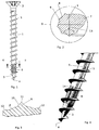
- FIG. 1 shows the side view of a screw according to the invention.
- the screw has a cylindrical screw shaft 1, at one in FIG. 1 upper end of a screw head 2 is formed. It is in this case a countersunk head.
- the screw tip 3 is formed at the countersunk head 2 of the screw opposite end of the shaft 1.
- the screw tip 3 has the shape of a pointed cone. It ends in a punctiform tip 4.
- a thread 5 extends over the entire length of the screw shaft 1. This thread 5 also leads via the screw tip 3 as far as the punctiform tip 4.
- scraper ribs 6 are formed, which extend in the longitudinal direction of the screw and extend in the illustrated embodiment, two windings of the thread 5. All scraper ribs 6 start in the same place and have the same length. You can already do that FIG. 1 can be seen that the radial extent of the doctor ribs 6 is significantly smaller than the outer diameter of the thread fifth
- FIG. 2 shows on an enlarged scale a cross section through the shank of the screw along line II-III in FIG. 1 , The cut is thus also through a turn 7 of the thread 5.
- the scraper ribs are approximately triangular in cross-section, and that their greatest radial extent facing away from the shaft 1 is flattened. Between individual scraper ribs 6, the surface 8 of the shaft 1 is visible.
- the scraper ribs 6 thus have in the circumferential direction at a distance which in the illustrated embodiment is about as large as the extension of the scraper rib 6 in the circumferential direction itself.
- FIG. 3 shows on an enlarged scale a section of the cross section of FIG. 2 .
- Each scraper rib 6 has a cross section in the form of a flattened triangle.
- the two boundary edges 10 of the doctor blade 6 enclose with each other an angle of 90 °, which in FIG. 2 is also marked.
- a flat 11 is present, so that there two edges 12 are formed, but have an obtuse angle.
- the surface 8 of the screw shaft 1 is free.
- FIG. 4 shows again that the scraper ribs 6 start at the point where the screw tip 3 merges into the shaft 1.
- the scraper ribs 6 are chamfered at their beginning and at their end by an inclined surface 14, so there form no sharp point.
Landscapes
- Engineering & Computer Science (AREA)
- General Engineering & Computer Science (AREA)
- Geometry (AREA)
- Physics & Mathematics (AREA)
- Mechanical Engineering (AREA)
- Dispersion Chemistry (AREA)
- Wood Science & Technology (AREA)
- Life Sciences & Earth Sciences (AREA)
- Chemical & Material Sciences (AREA)
- Details Of Spanners, Wrenches, And Screw Drivers And Accessories (AREA)
- Joining Of Building Structures In Genera (AREA)
- Extrusion Moulding Of Plastics Or The Like (AREA)
- Connection Of Plates (AREA)
- Fishing Rods (AREA)
Description
- Die Erfindung betrifft eine Spanplattenschraube. Solche Spanplattenschrauben haben ein Gewinde, das an die Verwendung dieser Art von Schrauben zum Einschrauben in Spanplatten angepasst ist. Sie können natürlich auch zur Befestigung in Holz verwendet werden.
- Es ist bereits eine Schraube dieser Art bekannt, die an dem Schaft zwischen den Gewindegängen in Längsrichtung der Schraube verlaufende vorspringende Rippen aufweist. Diese Rippen sollen eine Sicherung gegen Lockern der Schraube darstellen. Sie verlaufen über die gesamte Länge des Gewindes. Ihr Querschnitt ist rechteckig (
EP 705987 A1 - Weiterhin bekannt ist eine Schraube zur Verwendung bei aus Holz hergestellten Bauteilen (
EP 1411252 A2 ). Diese Schraube weist in einem sich über drei Gewindegänge erstreckenden vorderen Bereich eine Vielzahl von durch Nuten getrennten Vorsprüngen auf, die einen dreieckigen unsymmetrischen Querschnitt enthalten. Die Vorsprünge schließen unmittelbar aneinander an. Der Zweck dieser Rippen besteht darin, beim Einschrauben das Bohrloch durch Verdrängen des Materials aufzuweiten, ohne die Auszugsfestigkeit der Schraube herabzusetzen. - Weiterhin ist eine Holzschraube bekannt, die zwischen zwei benachbarten Windungen zwei radiale Vorsprünge aufweist. Die Vorsprünge bilden entweder Kanten oder sind abgerundet (
US 2003/0231940 A1 ). - Der Erfindung liegt die Aufgabe zu Grunde, eine Spanplattenschraube zu schaffen, die bei der Verwendung mit Holz oder holzähnlichem Material ein verbessertes Einschrauben und eine geringere Spaltwirkung erreicht, die aber auch noch für Dübelverschraubungen geeignet ist.
- Zur Lösung dieser Aufgabe schlägt die Erfindung eine Spanplattenschraube mit den im Anspruch 1 genannten Merkmalen vor. Weiterbildungen der Erfindung sind Gegenstand von Unteransprüchen.
- Es hat sich überraschenderweise herausgestellt, dass die dreieckige Querschnittsform mit der nicht abgerundeten, sondern abgeflachten Spitze diese Möglichkeiten bietet.
- In Weiterbildung der Erfindung kann vorgesehen sein, dass der Beginn der Schaberippen an der Stelle angeordnet ist, wo die konische Spitze der Schraube in den zylindrischen Schraubenschaft übergeht. Die Schaberippen selbst sind dann nur an dem zylindrischen Schraubenschaft ausgebildet.
- In nochmaliger Weiterbildung der Erfindung ist vorgesehen, dass die Schaberippen sich in Längsrichtung der Schraube über etwa eine bis zwei, maximal drei Windungen des Gewindes erstrecken. Eine längere Ausbildung der Schaberippen ist nicht erforderlich.
- Erfindungsgemäß kann in Weiterbildung vorgesehen sein, dass die radiale Erstreckung der Schaberippen, also ihr Überstand gegenüber der Oberfläche des Schafts, zwischen etwa 10% und 20% des Schaftdurchmessers liegt.
- Es hat sich als besonders sinnvoll herausgestellt, dass der Winkel zwischen den beiden Begrenzungsflanken jeder Schaberippe etwa 90° beträgt.
- Erfindungsgemäß kann vorgesehen sein, dass die Schaberippen gleichmäßig über den Umfang der Schraube verteilt angeordnet sind.
- Insbesondere ist vorgesehen, dass alle Schaberippen die gleiche Länge und die gleiche Anordnung und Ausbildung aufweisen. Es kann ebenfalls vorgesehen sein, dass alle Schaberippen die gleiche Querschnittsgröße und den gleichen Querschnitt aufweisen.
- Es hat sich als sinnvoll herausgestellt, je nach Größe der Schraube beispielsweise sieben oder neun Schaberippen vorzusehen. Auch jede andere Zahl von Rippen ist möglich.
- Sinnvollerweise können die Schaberippen einen symmetrischen Querschnitt aufweisen.
- Aufgrund der Größe und der Zahl der Schaberippen ergibt sich, dass zwischen den Schaberippen ein Abstand in Umfangsrichtung vorhanden ist, in dem die glatte Schaftoberfläche zugänglich ist.
- Dieser Abstand zwischen den Schaberippen kann beispielsweise zwischen 0,1 und 0,3 mm liegen, bei Schrauben der Nenngröße 3,5 bzw. 4,5 mm.
- Die Umfangserstreckung der flachen Außenseite der Schaberippen, also die abgeflachten Spitze, liegt beispielsweise in einem Bereich von 0,01 bis 0,03 mm.
- Weitere Merkmale, Einzelheiten und Vorzüge der Erfindung ergeben sich aus den Ansprüchen und der Zusammenfassung, deren beider Wortlaut durch Bezugnahme zum Inhalt der Beschreibung gemacht wird, der folgenden Beschreibung bevorzugter Ausführungsformen der Erfindung sowie anhand der Zeichnung. Hierbei zeigen:
- Figur 1
- eine Seitenansicht einer von der Erfindung vorgeschlagenen Spanplattenschraube;
- Figur 2
- in vergrößertem Maßstab einen Querschnitt durch die Schraube mit eingezeichnetem Gewindespitzendurchmesser;
- Figur 3
- in nochmals vergrößertem Maßstab die Form und Anordnung der Schaberippen;
- Figur 4
- eine perspektivische Ansicht des vorderen die Schaberippen aufweisenden Schraubenendes.
- Die
Figur 1 zeigt die Seitenansicht einer Schraube nach der Erfindung. Die Schraube hat einen zylindrischen Schraubenschaft 1, an dessen einem inFigur 1 oberen Ende ein Schraubenkopf 2 ausgebildet ist. Es handelt sich im vorliegenden Fall um einen Senkkopf. An dem dem Senkkopf 2 der Schraube gegenüberliegenden Ende des Schafts 1 ist die Schraubenspitze 3 ausgebildet. Die Schraubenspitze 3 weist die Form eines spitzen Kegels auf. Sie endet in einer punktförmigen Spitze 4. - Über die gesamte Länge des Schraubenschafts 1 erstreckt sich ein Gewinde 5. Dieses Gewinde 5 führt auch über die Schraubenspitze 3 bis zu der punktförmigen Spitze 4.
- In dem an die Schraubenspitze 3 angrenzenden Bereich des Schraubenschafts 1 sind mehrere Schaberippen 6 ausgebildet, die in Längsrichtung der Schraube verlaufen und sich im dargestellten Ausführungsbeispiel über zwei Windungen des Gewindes 5 erstrecken. Alle Schaberippen 6 beginnen an der gleichen Stelle und haben die gleiche Länge. Man kann schon der
Figur 1 entnehmen, dass die radiale Erstreckung der Schaberippen 6 deutlich kleiner ist als der Außendurchmesser des Gewindes 5. - Die
Figur 2 , auf die jetzt Bezug genommen wird, zeigt in vergrößertem Maßstab einen Querschnitt durch den Schaft der Schraube längs Linie II-III inFigur 1 . Der Schnitt geht also auch durch eine Windung 7 des Gewindes 5. Man kann derFigur 2 entnehmen, dass die Schaberippen im Querschnitt angenähert dreieckig sind, und dass ihre von dem Schaft 1 abgewandte größte radiale Erstreckung abgeflacht ist. Zwischen den einzelnen Schaberippen 6 ist die Oberfläche 8 des Schafts 1 sichtbar. Die Schaberippen 6 weisen also in Umfangsrichtung einen Abstand auf, der im dargestellten Ausführungsbeispiel etwa so groß ist wie die Erstreckung der Schaberippe 6 in Umfangsrichtung selbst. - Man kann ebenfalls sehen, dass die radiale Erstreckung der Schaberippen 6 gegenüber dem Abstand zwischen der Oberfläche 8 des Schraubenschafts 1 und dem Umfang 9 des Gewindes 5 klein ist.
- Die genaue Form der Schaberippen in ihrem Querschnitt geht aus
Figur 3 hervor.Figur 3 zeigt in vergrößertem Maßstab einen Ausschnitt aus dem Querschnitt derFigur 2 . Jeder Schaberippe 6 weist einen Querschnitt in Form eines abgeflachten Dreiecks auf. Die beiden Begrenzungsflanken 10 der Schaberippe 6 schließen miteinander einen Winkel von 90° ein, der inFigur 2 auch eingezeichnet ist. An ihrer gedachten Spitze ist eine Abflachung 11 vorhanden, so dass dort zwei Kanten 12 gebildet sind, die aber einen stumpfen Winkel haben. Zwischen jeweils zwei Schaberippen 6 ist, wie bereits erwähnt, die Oberfläche 8 des Schraubenschafts 1 frei. - Zeichnet man durch die Mitte der Abflachung 11 eine durch die Längsachse der Schraube gehende Linie ein, siehe die Linie 13 in
Figur 2 , so ist die Schaberippe 6 symmetrisch zu dieser Mittellinie. - Die vergrößerte perspektivische Ansicht der
Figur 4 zeigt nochmals, dass die Schaberippen 6 an der Stelle beginnen, wo die Schraubenspitze 3 in den Schaft 1 übergeht. Die Schaberippen 6 sind an ihrem Anfang und an ihrem Ende durch eine Schrägfläche 14 abgeschrägt, bilden also dort keine scharfe Spitze.
Claims (9)
- Spanplattenschraube, mit1.1 einem Schraubenkopf (2),1.2 einem Schraubenschaft (1),1.3 einer Schraubenspitze (3),1.4 einem sich über mindestens einen Teil des Schraubenschafts (1) und/oder die Schraubenspitze (3) erstreckenden Gewinde (5) sowie mit1.5 mehreren in Längsrichtung der Schraube verlaufenden Schaberippen (6), die1.6 einen dreieckigen Querschnitt mit einer abgeflachten Spitze aufweisen,dadurch gekennzeichnet, dass1.7 die Schaberippen (6) sich in Längsrichtung über etwa ein bis zwei Windungen des Gewindes (5) erstrecken,1.8 alle Schaberippen (6) die gleiche Länge und die gleiche Anordnung aufweisen und1.9 zwischen den Schaberippen die Schaftoberfläche zugänglich ist.
- Spanplattenschraube nach Anspruch 1, bei der die Schaberippen (6) im Bereich des Übergangs zwischen dem zylindrischen Schraubenschaft (1) und der konischen Schraubenspitze (3) beginnen und am Schraubenschaft (1) angeordnet sind.
- Spanplattenschraube nach Anspruch 1 oder 2, bei der die radiale Erstreckung der Schaberippen (6) zwischen etwa 10% und etwa 20% des Schaftdurchmessers liegt.
- Spanplattenschraube nach einem der vorhergehenden Ansprüche, bei der der Winkel zwischen den beiden Begrenzungsflanken (10) jeder Schaberippe (6) etwa 90° beträgt.
- Spanplattenschraube nach einem der vorhergehenden Ansprüche, bei der die Schaberippen (6) gleichmäßig über den Umfang der Schraube verteilt sind.
- Spanplattenschraube nach einem der vorhergehenden Ansprüche, bei der alle Schaberippen (6) die gleiche Querschnittsgröße aufweisen.
- Spanplattenschraube nach einem der vorhergehenden Ansprüche, mit zwischen sieben und zehn, vorzugsweise neun, Schaberippen (6).
- Spanplattenschraube nach einem der vorhergehenden Ansprüche, bei der der Querschnitt der Schaberippen (6) symmetrisch ausgebildet ist.
- Spanplattenschraube nach einem der vorhergehenden Ansprüche, bei der die Schaberippen (6) in Umfangsrichtung einen Abstand voneinander aufweisen.
Applications Claiming Priority (2)
| Application Number | Priority Date | Filing Date | Title |
|---|---|---|---|
| DE102011002962A DE102011002962A1 (de) | 2011-01-21 | 2011-01-21 | Spanplattenschraube |
| PCT/EP2012/050679 WO2012098139A1 (de) | 2011-01-21 | 2012-01-18 | Spanplattenschraube |
Publications (2)
| Publication Number | Publication Date |
|---|---|
| EP2665941A1 EP2665941A1 (de) | 2013-11-27 |
| EP2665941B1 true EP2665941B1 (de) | 2016-04-27 |
Family
ID=45509499
Family Applications (1)
| Application Number | Title | Priority Date | Filing Date |
|---|---|---|---|
| EP12700679.9A Revoked EP2665941B1 (de) | 2011-01-21 | 2012-01-18 | Spanplattenschraube |
Country Status (6)
| Country | Link |
|---|---|
| EP (1) | EP2665941B1 (de) |
| DE (1) | DE102011002962A1 (de) |
| DK (1) | DK2665941T3 (de) |
| ES (1) | ES2579316T3 (de) |
| PL (1) | PL2665941T3 (de) |
| WO (1) | WO2012098139A1 (de) |
Cited By (1)
| Publication number | Priority date | Publication date | Assignee | Title |
|---|---|---|---|---|
| US10859107B2 (en) | 2017-04-18 | 2020-12-08 | Würth International Ag | Wood screw having a crescent-shaped protrusion between thread turns |
Families Citing this family (5)
| Publication number | Priority date | Publication date | Assignee | Title |
|---|---|---|---|---|
| DE102014205464B4 (de) | 2014-03-24 | 2020-07-16 | Schmid Schrauben Hainfeld Gmbh | Schraube |
| GB2543515A (en) * | 2015-10-20 | 2017-04-26 | Yang Hui-Ju | Screw |
| CH713769A1 (de) * | 2017-05-12 | 2018-11-15 | Profix Ag | Holzschraube. |
| TWI733584B (zh) * | 2020-09-08 | 2021-07-11 | 甫商有限公司 | 具有切削凸牙的螺絲 |
| AT527323B1 (de) * | 2024-02-08 | 2025-01-15 | Avvio Gmbh & Co Kg | Schraube mit vergrößertem Kerndurchmesser im Ausreibabschnitt |
Citations (7)
| Publication number | Priority date | Publication date | Assignee | Title |
|---|---|---|---|---|
| US2263137A (en) | 1940-03-02 | 1941-11-18 | Parker Kalon Corp | Fastener device |
| EP0703897A1 (de) | 1993-06-15 | 1996-04-03 | Brigham & Women's Hospital | Lipoxinverbindungen |
| DE20216249U1 (de) | 2001-12-21 | 2002-12-19 | Chen, Shiu-Mei, Tu-Cheng, Taipeh | Schrauben für Holzplatten |
| DE69527755T2 (de) | 1994-10-04 | 2003-04-24 | Vynex, S.A. | Selbstschneidende gebohrte Kopfschraube |
| US20030231940A1 (en) | 2002-06-17 | 2003-12-18 | Chao-Wei Lin | Wood screw |
| EP1411252B1 (de) | 2002-08-29 | 2006-06-21 | Schmid Schrauben Hainfeld Gesellschaft m.b.H. | Schraube zur Verwendung bei aus Holz hergestellten Bauteilen |
| JP2010190269A (ja) | 2009-02-17 | 2010-09-02 | Pias Hanbai Kk | 硬質木材用タッピンねじ |
Family Cites Families (4)
| Publication number | Priority date | Publication date | Assignee | Title |
|---|---|---|---|---|
| JPH041371Y2 (de) * | 1987-02-16 | 1992-01-17 | ||
| FR2672091B1 (fr) * | 1991-01-30 | 1993-08-06 | Sigre Sa | Vis d'assemblage. |
| DE19525732A1 (de) * | 1995-07-14 | 1997-01-16 | Gaisbach Schraubenwerk Swg | Schraube |
| DE19532874A1 (de) * | 1995-09-06 | 1997-03-13 | Az Ausruest Zubehoer Gmbh | Gewindeformendes Verbindungselement |
-
2011
- 2011-01-21 DE DE102011002962A patent/DE102011002962A1/de not_active Withdrawn
-
2012
- 2012-01-18 DK DK12700679.9T patent/DK2665941T3/en active
- 2012-01-18 WO PCT/EP2012/050679 patent/WO2012098139A1/de not_active Ceased
- 2012-01-18 ES ES12700679.9T patent/ES2579316T3/es active Active
- 2012-01-18 EP EP12700679.9A patent/EP2665941B1/de not_active Revoked
- 2012-01-18 PL PL12700679.9T patent/PL2665941T3/pl unknown
Patent Citations (7)
| Publication number | Priority date | Publication date | Assignee | Title |
|---|---|---|---|---|
| US2263137A (en) | 1940-03-02 | 1941-11-18 | Parker Kalon Corp | Fastener device |
| EP0703897A1 (de) | 1993-06-15 | 1996-04-03 | Brigham & Women's Hospital | Lipoxinverbindungen |
| DE69527755T2 (de) | 1994-10-04 | 2003-04-24 | Vynex, S.A. | Selbstschneidende gebohrte Kopfschraube |
| DE20216249U1 (de) | 2001-12-21 | 2002-12-19 | Chen, Shiu-Mei, Tu-Cheng, Taipeh | Schrauben für Holzplatten |
| US20030231940A1 (en) | 2002-06-17 | 2003-12-18 | Chao-Wei Lin | Wood screw |
| EP1411252B1 (de) | 2002-08-29 | 2006-06-21 | Schmid Schrauben Hainfeld Gesellschaft m.b.H. | Schraube zur Verwendung bei aus Holz hergestellten Bauteilen |
| JP2010190269A (ja) | 2009-02-17 | 2010-09-02 | Pias Hanbai Kk | 硬質木材用タッピンねじ |
Cited By (1)
| Publication number | Priority date | Publication date | Assignee | Title |
|---|---|---|---|---|
| US10859107B2 (en) | 2017-04-18 | 2020-12-08 | Würth International Ag | Wood screw having a crescent-shaped protrusion between thread turns |
Also Published As
| Publication number | Publication date |
|---|---|
| WO2012098139A1 (de) | 2012-07-26 |
| ES2579316T3 (es) | 2016-08-09 |
| PL2665941T3 (pl) | 2016-11-30 |
| EP2665941A1 (de) | 2013-11-27 |
| DK2665941T3 (en) | 2016-08-15 |
| DE102011002962A1 (de) | 2012-07-26 |
Similar Documents
| Publication | Publication Date | Title |
|---|---|---|
| EP2012026B1 (de) | Schraube | |
| DE102006026176A1 (de) | Selbstbohrende Schraube | |
| EP3004666A1 (de) | Schraube | |
| AT412665B (de) | Schraube zur verwendung bei aus holz hergestellten bauteilen | |
| DE202004002877U1 (de) | Gewindeformende Schraube | |
| DE102006057259A1 (de) | Schraube | |
| DE102014205464B4 (de) | Schraube | |
| WO2012098139A1 (de) | Spanplattenschraube | |
| EP2150709A1 (de) | Spanplattenschraube | |
| DE102019219492A1 (de) | Schraube mit Fräserteil | |
| DE4016724C2 (de) | ||
| DE102015222281A1 (de) | Gewindeformende Schraube | |
| DE202007018179U1 (de) | Schraube | |
| DE202009014561U1 (de) | Schraube insbesondere für zementgebundene Faserplatten | |
| EP2372177B1 (de) | Spanplattenschraube | |
| DE102019205494A1 (de) | Schraube für Holzwerkstoffe | |
| DE102017208284B4 (de) | Holzschraube für den konstruktiven Holzbau | |
| EP2811181B1 (de) | Schraube | |
| DE10252774A1 (de) | Schraube für harte Werkstoffe | |
| EP3943763B1 (de) | Holz- oder kunststoffschraube | |
| EP3426937B1 (de) | Schraube | |
| DE10337250B4 (de) | Schraube mit selbstfurchendem Gewinde zum Eindrehen, insbesondere in Gasbeton, Holz und ähnlichen Werkstoff | |
| EP2470801B1 (de) | Schraube | |
| EP4461975B1 (de) | Selbstschneidende schraube | |
| DE102009025222A1 (de) | Furchschraube |
Legal Events
| Date | Code | Title | Description |
|---|---|---|---|
| PUAI | Public reference made under article 153(3) epc to a published international application that has entered the european phase |
Free format text: ORIGINAL CODE: 0009012 |
|
| 17P | Request for examination filed |
Effective date: 20130723 |
|
| AK | Designated contracting states |
Kind code of ref document: A1 Designated state(s): AL AT BE BG CH CY CZ DE DK EE ES FI FR GB GR HR HU IE IS IT LI LT LU LV MC MK MT NL NO PL PT RO RS SE SI SK SM TR |
|
| DAX | Request for extension of the european patent (deleted) | ||
| GRAP | Despatch of communication of intention to grant a patent |
Free format text: ORIGINAL CODE: EPIDOSNIGR1 |
|
| INTG | Intention to grant announced |
Effective date: 20151030 |
|
| GRAS | Grant fee paid |
Free format text: ORIGINAL CODE: EPIDOSNIGR3 |
|
| GRAA | (expected) grant |
Free format text: ORIGINAL CODE: 0009210 |
|
| AK | Designated contracting states |
Kind code of ref document: B1 Designated state(s): AL AT BE BG CH CY CZ DE DK EE ES FI FR GB GR HR HU IE IS IT LI LT LU LV MC MK MT NL NO PL PT RO RS SE SI SK SM TR |
|
| REG | Reference to a national code |
Ref country code: GB Ref legal event code: FG4D Free format text: NOT ENGLISH |
|
| REG | Reference to a national code |
Ref country code: CH Ref legal event code: EP |
|
| REG | Reference to a national code |
Ref country code: AT Ref legal event code: REF Ref document number: 795147 Country of ref document: AT Kind code of ref document: T Effective date: 20160515 |
|
| REG | Reference to a national code |
Ref country code: IE Ref legal event code: FG4D Free format text: LANGUAGE OF EP DOCUMENT: GERMAN |
|
| REG | Reference to a national code |
Ref country code: CH Ref legal event code: NV Representative=s name: DR. LUSUARDI AG, CH |
|
| REG | Reference to a national code |
Ref country code: DE Ref legal event code: R096 Ref document number: 502012006893 Country of ref document: DE |
|
| REG | Reference to a national code |
Ref country code: ES Ref legal event code: FG2A Ref document number: 2579316 Country of ref document: ES Kind code of ref document: T3 Effective date: 20160809 |
|
| REG | Reference to a national code |
Ref country code: DK Ref legal event code: T3 Effective date: 20160812 |
|
| REG | Reference to a national code |
Ref country code: LT Ref legal event code: MG4D |
|
| REG | Reference to a national code |
Ref country code: NL Ref legal event code: MP Effective date: 20160427 |
|
| REG | Reference to a national code |
Ref country code: NO Ref legal event code: T2 Effective date: 20160427 |
|
| PG25 | Lapsed in a contracting state [announced via postgrant information from national office to epo] |
Ref country code: NL Free format text: LAPSE BECAUSE OF FAILURE TO SUBMIT A TRANSLATION OF THE DESCRIPTION OR TO PAY THE FEE WITHIN THE PRESCRIBED TIME-LIMIT Effective date: 20160427 |
|
| PG25 | Lapsed in a contracting state [announced via postgrant information from national office to epo] |
Ref country code: FI Free format text: LAPSE BECAUSE OF FAILURE TO SUBMIT A TRANSLATION OF THE DESCRIPTION OR TO PAY THE FEE WITHIN THE PRESCRIBED TIME-LIMIT Effective date: 20160427 Ref country code: LT Free format text: LAPSE BECAUSE OF FAILURE TO SUBMIT A TRANSLATION OF THE DESCRIPTION OR TO PAY THE FEE WITHIN THE PRESCRIBED TIME-LIMIT Effective date: 20160427 |
|
| PG25 | Lapsed in a contracting state [announced via postgrant information from national office to epo] |
Ref country code: SE Free format text: LAPSE BECAUSE OF FAILURE TO SUBMIT A TRANSLATION OF THE DESCRIPTION OR TO PAY THE FEE WITHIN THE PRESCRIBED TIME-LIMIT Effective date: 20160427 Ref country code: RS Free format text: LAPSE BECAUSE OF FAILURE TO SUBMIT A TRANSLATION OF THE DESCRIPTION OR TO PAY THE FEE WITHIN THE PRESCRIBED TIME-LIMIT Effective date: 20160427 Ref country code: PT Free format text: LAPSE BECAUSE OF FAILURE TO SUBMIT A TRANSLATION OF THE DESCRIPTION OR TO PAY THE FEE WITHIN THE PRESCRIBED TIME-LIMIT Effective date: 20160829 Ref country code: LV Free format text: LAPSE BECAUSE OF FAILURE TO SUBMIT A TRANSLATION OF THE DESCRIPTION OR TO PAY THE FEE WITHIN THE PRESCRIBED TIME-LIMIT Effective date: 20160427 Ref country code: GR Free format text: LAPSE BECAUSE OF FAILURE TO SUBMIT A TRANSLATION OF THE DESCRIPTION OR TO PAY THE FEE WITHIN THE PRESCRIBED TIME-LIMIT Effective date: 20160728 Ref country code: HR Free format text: LAPSE BECAUSE OF FAILURE TO SUBMIT A TRANSLATION OF THE DESCRIPTION OR TO PAY THE FEE WITHIN THE PRESCRIBED TIME-LIMIT Effective date: 20160427 |
|
| REG | Reference to a national code |
Ref country code: FR Ref legal event code: PLFP Year of fee payment: 6 |
|
| REG | Reference to a national code |
Ref country code: DE Ref legal event code: R026 Ref document number: 502012006893 Country of ref document: DE |
|
| PG25 | Lapsed in a contracting state [announced via postgrant information from national office to epo] |
Ref country code: EE Free format text: LAPSE BECAUSE OF FAILURE TO SUBMIT A TRANSLATION OF THE DESCRIPTION OR TO PAY THE FEE WITHIN THE PRESCRIBED TIME-LIMIT Effective date: 20160427 Ref country code: SK Free format text: LAPSE BECAUSE OF FAILURE TO SUBMIT A TRANSLATION OF THE DESCRIPTION OR TO PAY THE FEE WITHIN THE PRESCRIBED TIME-LIMIT Effective date: 20160427 Ref country code: RO Free format text: LAPSE BECAUSE OF FAILURE TO SUBMIT A TRANSLATION OF THE DESCRIPTION OR TO PAY THE FEE WITHIN THE PRESCRIBED TIME-LIMIT Effective date: 20160427 |
|
| PLBI | Opposition filed |
Free format text: ORIGINAL CODE: 0009260 |
|
| PG25 | Lapsed in a contracting state [announced via postgrant information from national office to epo] |
Ref country code: SM Free format text: LAPSE BECAUSE OF FAILURE TO SUBMIT A TRANSLATION OF THE DESCRIPTION OR TO PAY THE FEE WITHIN THE PRESCRIBED TIME-LIMIT Effective date: 20160427 |
|
| 26 | Opposition filed |
Opponent name: SPAX INTERNATIONAL GMBH & CO. KG Effective date: 20170126 |
|
| PLAX | Notice of opposition and request to file observation + time limit sent |
Free format text: ORIGINAL CODE: EPIDOSNOBS2 |
|
| PG25 | Lapsed in a contracting state [announced via postgrant information from national office to epo] |
Ref country code: BE Free format text: LAPSE BECAUSE OF NON-PAYMENT OF DUE FEES Effective date: 20170131 Ref country code: SI Free format text: LAPSE BECAUSE OF FAILURE TO SUBMIT A TRANSLATION OF THE DESCRIPTION OR TO PAY THE FEE WITHIN THE PRESCRIBED TIME-LIMIT Effective date: 20160427 |
|
| PLBB | Reply of patent proprietor to notice(s) of opposition received |
Free format text: ORIGINAL CODE: EPIDOSNOBS3 |
|
| PG25 | Lapsed in a contracting state [announced via postgrant information from national office to epo] |
Ref country code: MC Free format text: LAPSE BECAUSE OF FAILURE TO SUBMIT A TRANSLATION OF THE DESCRIPTION OR TO PAY THE FEE WITHIN THE PRESCRIBED TIME-LIMIT Effective date: 20160427 |
|
| REG | Reference to a national code |
Ref country code: IE Ref legal event code: MM4A |
|
| PG25 | Lapsed in a contracting state [announced via postgrant information from national office to epo] |
Ref country code: LU Free format text: LAPSE BECAUSE OF NON-PAYMENT OF DUE FEES Effective date: 20170118 |
|
| REG | Reference to a national code |
Ref country code: FR Ref legal event code: PLFP Year of fee payment: 7 |
|
| REG | Reference to a national code |
Ref country code: BE Ref legal event code: MM Effective date: 20170131 |
|
| PG25 | Lapsed in a contracting state [announced via postgrant information from national office to epo] |
Ref country code: IE Free format text: LAPSE BECAUSE OF NON-PAYMENT OF DUE FEES Effective date: 20170118 |
|
| PGFP | Annual fee paid to national office [announced via postgrant information from national office to epo] |
Ref country code: PL Payment date: 20171220 Year of fee payment: 7 |
|
| PLAB | Opposition data, opponent's data or that of the opponent's representative modified |
Free format text: ORIGINAL CODE: 0009299OPPO |
|
| R26 | Opposition filed (corrected) |
Opponent name: SPAX INTERNATIONAL GMBH & CO. KG Effective date: 20170126 |
|
| PGFP | Annual fee paid to national office [announced via postgrant information from national office to epo] |
Ref country code: CH Payment date: 20180119 Year of fee payment: 7 Ref country code: ES Payment date: 20180227 Year of fee payment: 7 Ref country code: CZ Payment date: 20180116 Year of fee payment: 7 Ref country code: DE Payment date: 20180122 Year of fee payment: 7 Ref country code: DK Payment date: 20180119 Year of fee payment: 7 Ref country code: GB Payment date: 20180119 Year of fee payment: 7 Ref country code: NO Payment date: 20180130 Year of fee payment: 7 |
|
| PGFP | Annual fee paid to national office [announced via postgrant information from national office to epo] |
Ref country code: IT Payment date: 20180129 Year of fee payment: 7 Ref country code: FR Payment date: 20180119 Year of fee payment: 7 Ref country code: AT Payment date: 20180122 Year of fee payment: 7 |
|
| REG | Reference to a national code |
Ref country code: DE Ref legal event code: R064 Ref document number: 502012006893 Country of ref document: DE Ref country code: DE Ref legal event code: R103 Ref document number: 502012006893 Country of ref document: DE |
|
| RDAF | Communication despatched that patent is revoked |
Free format text: ORIGINAL CODE: EPIDOSNREV1 |
|
| STAA | Information on the status of an ep patent application or granted ep patent |
Free format text: STATUS: THE PATENT HAS BEEN GRANTED |
|
| PG25 | Lapsed in a contracting state [announced via postgrant information from national office to epo] |
Ref country code: MT Free format text: LAPSE BECAUSE OF FAILURE TO SUBMIT A TRANSLATION OF THE DESCRIPTION OR TO PAY THE FEE WITHIN THE PRESCRIBED TIME-LIMIT Effective date: 20160427 |
|
| RDAG | Patent revoked |
Free format text: ORIGINAL CODE: 0009271 |
|
| STAA | Information on the status of an ep patent application or granted ep patent |
Free format text: STATUS: PATENT REVOKED |
|
| REG | Reference to a national code |
Ref country code: CH Ref legal event code: PL |
|
| 27W | Patent revoked |
Effective date: 20180625 |
|
| GBPR | Gb: patent revoked under art. 102 of the ep convention designating the uk as contracting state |
Effective date: 20180625 |
|
| PG25 | Lapsed in a contracting state [announced via postgrant information from national office to epo] |
Ref country code: AL Free format text: LAPSE BECAUSE OF FAILURE TO SUBMIT A TRANSLATION OF THE DESCRIPTION OR TO PAY THE FEE WITHIN THE PRESCRIBED TIME-LIMIT Effective date: 20160427 |
|
| REG | Reference to a national code |
Ref country code: AT Ref legal event code: MA03 Ref document number: 795147 Country of ref document: AT Kind code of ref document: T Effective date: 20180625 |
|
| PG25 | Lapsed in a contracting state [announced via postgrant information from national office to epo] |
Ref country code: BG Free format text: LAPSE BECAUSE OF FAILURE TO SUBMIT A TRANSLATION OF THE DESCRIPTION OR TO PAY THE FEE WITHIN THE PRESCRIBED TIME-LIMIT Effective date: 20160427 |
|
| PG25 | Lapsed in a contracting state [announced via postgrant information from national office to epo] |
Ref country code: MK Free format text: LAPSE BECAUSE OF FAILURE TO SUBMIT A TRANSLATION OF THE DESCRIPTION OR TO PAY THE FEE WITHIN THE PRESCRIBED TIME-LIMIT Effective date: 20160427 |
|
| PG25 | Lapsed in a contracting state [announced via postgrant information from national office to epo] |
Ref country code: CY Free format text: LAPSE BECAUSE OF FAILURE TO SUBMIT A TRANSLATION OF THE DESCRIPTION OR TO PAY THE FEE WITHIN THE PRESCRIBED TIME-LIMIT Effective date: 20160427 |
|
| PG25 | Lapsed in a contracting state [announced via postgrant information from national office to epo] |
Ref country code: IS Free format text: LAPSE BECAUSE OF FAILURE TO SUBMIT A TRANSLATION OF THE DESCRIPTION OR TO PAY THE FEE WITHIN THE PRESCRIBED TIME-LIMIT Effective date: 20160827 |
|
| PG25 | Lapsed in a contracting state [announced via postgrant information from national office to epo] |
Ref country code: TR Free format text: LAPSE BECAUSE OF FAILURE TO SUBMIT A TRANSLATION OF THE DESCRIPTION OR TO PAY THE FEE WITHIN THE PRESCRIBED TIME-LIMIT Effective date: 20160427 |