EP2665420B1 - X-ray system and method for producing x-ray image data - Google Patents
X-ray system and method for producing x-ray image data Download PDFInfo
- Publication number
- EP2665420B1 EP2665420B1 EP12702115.2A EP12702115A EP2665420B1 EP 2665420 B1 EP2665420 B1 EP 2665420B1 EP 12702115 A EP12702115 A EP 12702115A EP 2665420 B1 EP2665420 B1 EP 2665420B1
- Authority
- EP
- European Patent Office
- Prior art keywords
- detector
- ray
- image data
- exposure
- imaging
- Prior art date
- Legal status (The legal status is an assumption and is not a legal conclusion. Google has not performed a legal analysis and makes no representation as to the accuracy of the status listed.)
- Active
Links
- 238000004519 manufacturing process Methods 0.000 title 1
- 238000003384 imaging method Methods 0.000 claims description 121
- 238000000034 method Methods 0.000 claims description 68
- 238000005070 sampling Methods 0.000 claims description 42
- 230000005855 radiation Effects 0.000 claims description 32
- 238000004891 communication Methods 0.000 claims description 28
- 238000012545 processing Methods 0.000 claims description 15
- 230000000977 initiatory effect Effects 0.000 claims description 9
- 238000004846 x-ray emission Methods 0.000 claims description 3
- 230000008569 process Effects 0.000 description 14
- 238000002360 preparation method Methods 0.000 description 7
- 238000012552 review Methods 0.000 description 7
- 238000010586 diagram Methods 0.000 description 6
- 230000006870 function Effects 0.000 description 6
- 239000011159 matrix material Substances 0.000 description 6
- 230000004044 response Effects 0.000 description 4
- 238000005201 scrubbing Methods 0.000 description 4
- 230000007423 decrease Effects 0.000 description 3
- 230000003993 interaction Effects 0.000 description 3
- 238000002601 radiography Methods 0.000 description 3
- 239000010409 thin film Substances 0.000 description 3
- 239000004020 conductor Substances 0.000 description 2
- 230000005669 field effect Effects 0.000 description 2
- 239000010408 film Substances 0.000 description 2
- 238000005286 illumination Methods 0.000 description 2
- 238000009420 retrofitting Methods 0.000 description 2
- 238000012546 transfer Methods 0.000 description 2
- 230000000007 visual effect Effects 0.000 description 2
- 238000012935 Averaging Methods 0.000 description 1
- 230000002411 adverse Effects 0.000 description 1
- 229910021417 amorphous silicon Inorganic materials 0.000 description 1
- 210000003484 anatomy Anatomy 0.000 description 1
- 238000013170 computed tomography imaging Methods 0.000 description 1
- 230000001419 dependent effect Effects 0.000 description 1
- 238000003745 diagnosis Methods 0.000 description 1
- 238000002059 diagnostic imaging Methods 0.000 description 1
- 230000000694 effects Effects 0.000 description 1
- 238000001914 filtration Methods 0.000 description 1
- 230000003116 impacting effect Effects 0.000 description 1
- 238000007689 inspection Methods 0.000 description 1
- 238000005259 measurement Methods 0.000 description 1
- 239000002184 metal Substances 0.000 description 1
- ORQBXQOJMQIAOY-UHFFFAOYSA-N nobelium Chemical compound [No] ORQBXQOJMQIAOY-UHFFFAOYSA-N 0.000 description 1
- 238000003825 pressing Methods 0.000 description 1
- 238000011084 recovery Methods 0.000 description 1
- 230000009467 reduction Effects 0.000 description 1
- 238000003530 single readout Methods 0.000 description 1
- 230000007704 transition Effects 0.000 description 1
Images


Classifications
-
- A—HUMAN NECESSITIES
- A61—MEDICAL OR VETERINARY SCIENCE; HYGIENE
- A61B—DIAGNOSIS; SURGERY; IDENTIFICATION
- A61B6/00—Apparatus or devices for radiation diagnosis; Apparatus or devices for radiation diagnosis combined with radiation therapy equipment
-
- A—HUMAN NECESSITIES
- A61—MEDICAL OR VETERINARY SCIENCE; HYGIENE
- A61B—DIAGNOSIS; SURGERY; IDENTIFICATION
- A61B6/00—Apparatus or devices for radiation diagnosis; Apparatus or devices for radiation diagnosis combined with radiation therapy equipment
- A61B6/42—Arrangements for detecting radiation specially adapted for radiation diagnosis
- A61B6/4208—Arrangements for detecting radiation specially adapted for radiation diagnosis characterised by using a particular type of detector
- A61B6/4233—Arrangements for detecting radiation specially adapted for radiation diagnosis characterised by using a particular type of detector using matrix detectors
-
- A—HUMAN NECESSITIES
- A61—MEDICAL OR VETERINARY SCIENCE; HYGIENE
- A61B—DIAGNOSIS; SURGERY; IDENTIFICATION
- A61B6/00—Apparatus or devices for radiation diagnosis; Apparatus or devices for radiation diagnosis combined with radiation therapy equipment
- A61B6/42—Arrangements for detecting radiation specially adapted for radiation diagnosis
- A61B6/4283—Arrangements for detecting radiation specially adapted for radiation diagnosis characterised by a detector unit being housed in a cassette
-
- A—HUMAN NECESSITIES
- A61—MEDICAL OR VETERINARY SCIENCE; HYGIENE
- A61B—DIAGNOSIS; SURGERY; IDENTIFICATION
- A61B6/00—Apparatus or devices for radiation diagnosis; Apparatus or devices for radiation diagnosis combined with radiation therapy equipment
- A61B6/44—Constructional features of apparatus for radiation diagnosis
- A61B6/4411—Constructional features of apparatus for radiation diagnosis the apparatus being modular
-
- A—HUMAN NECESSITIES
- A61—MEDICAL OR VETERINARY SCIENCE; HYGIENE
- A61B—DIAGNOSIS; SURGERY; IDENTIFICATION
- A61B6/00—Apparatus or devices for radiation diagnosis; Apparatus or devices for radiation diagnosis combined with radiation therapy equipment
- A61B6/52—Devices using data or image processing specially adapted for radiation diagnosis
- A61B6/5205—Devices using data or image processing specially adapted for radiation diagnosis involving processing of raw data to produce diagnostic data
-
- A—HUMAN NECESSITIES
- A61—MEDICAL OR VETERINARY SCIENCE; HYGIENE
- A61B—DIAGNOSIS; SURGERY; IDENTIFICATION
- A61B6/00—Apparatus or devices for radiation diagnosis; Apparatus or devices for radiation diagnosis combined with radiation therapy equipment
- A61B6/56—Details of data transmission or power supply, e.g. use of slip rings
- A61B6/563—Details of data transmission or power supply, e.g. use of slip rings involving image data transmission via a network
-
- A—HUMAN NECESSITIES
- A61—MEDICAL OR VETERINARY SCIENCE; HYGIENE
- A61B—DIAGNOSIS; SURGERY; IDENTIFICATION
- A61B6/00—Apparatus or devices for radiation diagnosis; Apparatus or devices for radiation diagnosis combined with radiation therapy equipment
- A61B6/56—Details of data transmission or power supply, e.g. use of slip rings
- A61B6/566—Details of data transmission or power supply, e.g. use of slip rings involving communication between diagnostic systems
-
- A—HUMAN NECESSITIES
- A61—MEDICAL OR VETERINARY SCIENCE; HYGIENE
- A61B—DIAGNOSIS; SURGERY; IDENTIFICATION
- A61B6/00—Apparatus or devices for radiation diagnosis; Apparatus or devices for radiation diagnosis combined with radiation therapy equipment
- A61B6/44—Constructional features of apparatus for radiation diagnosis
- A61B6/4405—Constructional features of apparatus for radiation diagnosis the apparatus being movable or portable, e.g. handheld or mounted on a trolley
-
- A—HUMAN NECESSITIES
- A61—MEDICAL OR VETERINARY SCIENCE; HYGIENE
- A61B—DIAGNOSIS; SURGERY; IDENTIFICATION
- A61B6/00—Apparatus or devices for radiation diagnosis; Apparatus or devices for radiation diagnosis combined with radiation therapy equipment
- A61B6/44—Constructional features of apparatus for radiation diagnosis
- A61B6/4429—Constructional features of apparatus for radiation diagnosis related to the mounting of source units and detector units
- A61B6/4464—Constructional features of apparatus for radiation diagnosis related to the mounting of source units and detector units the source unit or the detector unit being mounted to ceiling
-
- A—HUMAN NECESSITIES
- A61—MEDICAL OR VETERINARY SCIENCE; HYGIENE
- A61B—DIAGNOSIS; SURGERY; IDENTIFICATION
- A61B6/00—Apparatus or devices for radiation diagnosis; Apparatus or devices for radiation diagnosis combined with radiation therapy equipment
- A61B6/44—Constructional features of apparatus for radiation diagnosis
- A61B6/4494—Means for identifying the diagnostic device
-
- A—HUMAN NECESSITIES
- A61—MEDICAL OR VETERINARY SCIENCE; HYGIENE
- A61B—DIAGNOSIS; SURGERY; IDENTIFICATION
- A61B6/00—Apparatus or devices for radiation diagnosis; Apparatus or devices for radiation diagnosis combined with radiation therapy equipment
- A61B6/56—Details of data transmission or power supply, e.g. use of slip rings
Definitions
- the subject matter disclosed herein relates to X-ray imaging systems and more particularly to X-ray imaging system using digital detectors.
- an X-ray imaging method includes performing an X-ray exposure via an X-ray radiation source responsive to a source controller.
- the method also includes sampling X-ray image data via a digital detector without communication of timing signals from the source controller.
- the method further includes combining the sampled X-ray image data of at least one imaging frame or two or more imaging frames with at least one of the frames spanning a duration in which the exposure occurred, to produce X-ray image data capable of being reconstructed into a user-viewable image.
- an X-ray imaging method includes performing an X-ray exposure via an X-ray radiation source.
- the method also includes sampling X-ray image data via a digital detector without a priori knowledge of beginning and ending times of the X-ray exposure.
- the method further includes determining beginning and ending frames of the X-ray image data.
- the method yet further includes combining the sampled X-ray image data of at least one imaging frame or two or more imaging frames with at least one of the frames spanning a duration in which the exposure occurred, to produce X-ray image data capable of being reconstructed into a user-viewable image.
- the X-ray imaging system includes an X-ray radiation source, a source controller coupled to the source and configured to command X-ray emission of X-rays for image exposures, and a digital X-ray detector configured to sample X-ray image data without communication from the source controller.
- the system also includes a portable detector control device configured to communicate instructions to the detector for acquisition of the X-ray image data and to receive the X-ray image data from the detector for processing and preview.
- At least one of the detector, the portable detector control device, and a processing system in communication with the detector and/or the portable detector control device is configured to combine the sampled X-ray image data of at least one imaging frame or two or more imaging frames with at least one of the frames spanning a duration in which the exposure occurred, to produce X-ray image data capable of being reconstructed into a user-viewable image.
- an X-ray system is represented, referenced generally by reference numeral 10.
- the X-ray system 10 is a digital X-ray system.
- the X-ray system 10 is designed both to acquire image data and to process the image data for display in accordance with the present technique.
- digital detectors including X-ray detectors, used in different settings (e.g., projection X-ray, computed tomography imaging, tomosynthesis imaging, etc.) and for different purposes (e.g., parcel, baggage, vehicle and part inspection, etc.).
- X-ray detectors used in different settings (e.g., projection X-ray, computed tomography imaging, tomosynthesis imaging, etc.) and for different purposes (e.g., parcel, baggage, vehicle and part inspection, etc.).
- the X-ray system 10 includes an imaging system 12.
- the imaging system 12 may be a conventional analog imaging system, retrofitted for digital image data acquisition and processing as described below.
- the imaging system 12 may be a stationary system disposed in a fixed X-ray imaging room, such as that generally depicted in and described below with respect to FIG. 1 . It will be appreciated, however, that the presently disclosed techniques may also be employed with other imaging systems, including mobile X-ray units and systems in other embodiments.
- the imaging system 12 includes an overhead tube support arm 14 for positioning a radiation source 16, such as an X-ray tube, and a collimator 18 with respect to a patient 20 and a detector 22.
- the detector 22 includes a digital X-ray detector.
- the detector 22 may be selected from a plurality of detectors 22, represented by detector 24, from a dock 26 (e.g., charging dock). Each detector 22 of the plurality of detectors 22 may be labeled and designed for a particular type of imaging (e.g., fluoroscopic and radiographic imaging).
- the detector 22 is configured to acquire X-ray image data without communication from a controller of the X-ray radiation source 16. In other words, the detector 22 is without communication of timing signals from the controller of the source 16 as to an X-ray exposure.
- the detector 22 in preparation for acquiring X-ray image data the detector 22 is configured to continuously sample data prior to and during an X-ray exposure. Also, the detector 22 is configured to combine multiple frames that include imaging data to generate X-ray images.
- the detector 22 is configured to at least partially process X-ray image data.
- the imaging system 12 may be used in consort with one or both of a patient table 28 and a wall stand 30 to facilitate image acquisition.
- the table 28 and the wall stand 30 may be configured to receive detector 22.
- detector 22 may be placed on an upper, lower or intermediate surface of the table 28, and the patient 20 (more specifically, an anatomy of interest of the patient 20) may be positioned on the table 28 between the detector 22 and the radiation source 16.
- the wall stand 30 may include a receiving structure 32 also adapted to receive the detector 22, and the patient 20 may be positioned adjacent the wall stand 30 to enable the image data to be acquired via the detector 22.
- the receiving structure 32 may be moved vertically along the wall stand 30.
- the imaging system 12 includes a workstation 34, display 36, and printer 37.
- the workstation 34 may include or provide the functionality of the imaging system 12 such that a user 38, by interacting with the workstation 34 may control operation of the source 16 and detector 22.
- the functions of the imaging system 12 may be decentralized, such that some functions of the imaging system 12 are performed at the workstation 34 (e.g., controlling operation of the source 16, while other functions (e.g., controlling operation of the detector 22) are performed by another component of the X-ray system 10, such as a portable detector control device 40.
- the portable detector control device 40 may include a personal digital assistant (PDA), palmtop computer, laptop computer, smart telephone, tablet computer such as an iPadTM, or any suitable general purpose or dedicated portable interface device.
- PDA personal digital assistant
- the portable detector control device 40 is configured to be held by the user 38 and to communicate wirelessly with the detector 22.
- the detector 22 and portable detector control device 40 may utilize any suitable wireless communication protocol, such as an IEEE 802.15.4 protocol, an ultra wideband (UWB) communication standard, a Bluetooth communication standard, or any IEEE 802.11 communication standard.
- the portable detector control device may be configured to be tethered or detachably tethered to the detector 22 to communicate via a wired connection.
- the portable detector control device 40 is also configured to communicate instructions (e.g., detector operating mode) to the detector 22 for the acquisition of X-ray image data.
- the detector 22 is configured to prepare for an X-ray exposure in response to instructions from the portable detector control device 40, and to transmit a detector ready signal to the device 40 indicating that the detector 22 is prepared to receive the X-ray exposure.
- the device 40 may also be configured to communicate patient information or X-ray technique information to the detector 22. Similar to the detector 22, the device 40 may be without communication from the controller of the X-ray source16. Further, the portable detector control device 40 is configured to receive X-ray image data from the detector 22 for processing and image reconstruction.
- both the detector 22 and the portable detector control device 40 are configured to at least partially process the X-ray image data.
- the detector 22 and/or the portable detector control device 40 are configured to fully process the X-ray image data.
- the detector 22 and/or the device 40 is configured to generate a DICOM compliant data file based upon the X-ray image data, patient information, and other information.
- the detector 22 and/or the device 40 is configured to wirelessly transmit (or via a wired connection) processed X-ray image data (e.g., partially or fully processed X-ray image data) to an institution image review and storage system over a network 42.
- the institution image review and storage system may include a hospital information system (HIS), a radiology information system (RIS), and/or picture archiving communication system (PACS).
- the institution image review and storage system may process the X-ray image data.
- the workstation 34 may be configured to function as a server of instructions and/or content on a network 42 of the medical facility.
- the detector 22 and/or device 40 are also configured to transmit, via a wired or wireless connection, processed X-ray images to the printer 37 to generate a copy of the image.
- the portable detector control device 40 includes a user-viewable screen 44 and is configured to display patient data and reconstructed X-ray images based upon X-ray image data on the screen 44.
- the screen 44 may include a touch-screen and/or input device (e.g., keyboard) configured to input data (e.g., patient data) and/or commands (e.g., to the detector).
- the device 40 may be used to input patient information and other imaging related information (e.g., type of source 16, imaging parameters, etc.) to form a DICOM image header.
- the patient information may be transferred from a patient database via a wireless or wired connection from the network or the workstation 34 to the device 40.
- the detector 22 and/or device may incorporate the information for the image header with the X-ray image to generate the DICOM compliant data file.
- the device 40 may be used to navigate X-ray images displayed on the screen 44. Further, the device 40 may be used to modify the X-ray images, for example, by adding position markers (e.g., "L”/ "R” for left and right, respectively) onto the image. In one embodiment, metal markers may be placed on the detector 22 to generate position markers.
- the imaging system 12 may be a stationary system disposed in a fixed X-ray imaging room, such as that generally depicted in and described above with respect to FIG. 1 . It will be appreciated, however, that the presently disclosed techniques may also be employed with other imaging systems, including mobile X-ray units and systems, in other embodiments.
- the imaging system 12 may be moved to a patient recovery room, an emergency room, a surgical room, or any other space to enable imaging of the patient 20 without requiring transport of the patient 20 to a dedicated (i.e., fixed) X-ray imaging room.
- the imaging system 12 includes a mobile X-ray base station 39 and detector 22. Similar to above, the imaging system 12 may be a conventional analog imaging system, retrofitted for digital image data acquisition and processing.
- a support arm 41 may be vertically moved along a support column 43 to facilitate positioning of the radiation source 16 and collimator 18 with respect to the patient 20.
- the support arm 41 and support column 43 may also be configured to allow rotation of the radiation source 16 about an axis.
- the X-ray base station 39 has a wheeled base 45 for movement of the station 39.
- Systems electronic circuitry 46 with a base unit 47 both provides and controls power to the X-ray source 16 and the wheeled base 45 in the imaging system 12.
- the base unit 47 also has the operator workstation 34 and display 36 that enables the user 38 to operate the X-ray system 10.
- the operator workstation 34 may include buttons, switches, or the like to facilitate operation of the X-ray source 16. Similar to the X-ray system 10 in FIG. 1 , the system 10 includes the portable control device 40.
- the detector 22 and portable control device 40 are as described above.
- the patient 20 may be located on a bed 49 (or gurney, table or any other support) between the X-ray source 16 and the detector 22 and subjected to X-rays that pass through the patient 20 and are received by the detector 22.
- a bed 49 or gurney, table or any other support
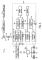
- FIG. 3 is a diagrammatical overview of the X-ray system 10 in FIGS. 1 and 2 illustrating the components of the system 10 in more detail.
- the imaging system 10 includes the X-ray radiation source 16 positioned adjacent to a collimator 18. Collimator 18 permits a stream of radiation 48 to pass into a region in which a subject 20, such as a human patient 20, is positioned. A portion of the radiation 50 passes through or around the subject 20 and impacts the digital X-ray detector 22. As described more fully below, detector 22 converts the X-ray photons received on its surface to lower energy photons, and subsequently to electric signals which are acquired and processed to reconstruct an image of the features within the subject 20.
- the source 16 is coupled to a power supply 52 which furnishes power for examination sequences.
- the source 16 and power supply 52 are coupled to a source controller 54 configured to command X-ray emission of X-rays for image exposures.
- the detector 22 is configured to acquire X-ray image data without communication from the source controller 54. Instead, the detector 22 is responsive to the portable detector control device 40 configured to communicate instructions the detector 22 for acquisition of the X-ray image data.
- the portable detector control device 40 is configured to receive the X-ray image data from the detector 22 for processing and imaging reconstruction.
- the detector 22 includes a wireless communication interface 56 for wireless communication with the device 40, as well as a wired communication interface 58, for communicating with the device 40 when it is tethered to the detector 22.
- the detector 22 and the device may also be in communication with the institution image review and storage system over the network 42 via a wired or wireless connection.
- the institution image review and storage system may include PACS 60, RIS 62, and HIS 64.
- the wireless communication interface 56 may utilize any suitable wireless communication protocol, such as an ultra wideband (UWB) communication standard, a Bluetooth communication standard, or any 802.11 communication standard.
- detector 22 is coupled to a detector controller 66 which coordinates the control of the various detector functions.
- detector controller 66 may execute various signal processing and filtration functions, such as for initial adjustment of dynamic ranges, interleaving of digital image data, and so forth.
- the detector controller 66 is responsive to signals from the device 40.
- the detector controller 66 is linked to a processor 68.
- the processor 68, the detector controller 66, and all of the circuitry receive power from a power supply 70.
- the power supply 70 may include one or more batteries.
- the processor 68 is linked to detector interface circuitry 72.
- the detector 22 converts X-ray photons received on its surface to lower energy photons.
- the detector 22 includes a detector array 74 that includes an array of photodetectors to convert the light photons to electrical signals. Alternatively, the detector 22 may convert the X-ray photons directly to electrical signals. These electrical signals are converted to digital values by the detector interface circuitry 72 which provides the values to the processor 68 to be converted to imaging data and sent to the device 40 to reconstruct an image of the features within the subject 20.
- the detector 22 may at least partially process or fully process the imaging data.
- the imaging data may be sent from the detector 22 to a server to process the imaging data.
- the processor 68 is also linked to an illumination circuit 76.
- the detector controller 66 in response to a signal received from the device 40, may send a signal to the processor 68 to signal the illumination circuit 76 to illuminate a light 78 to indicate the detector 22 is prepared to receive an X-ray exposure in response to the signal. Indeed, in response to a signal from the device 40, the detector 22 may be turned on or awoken from an idle state. Alternatively, the detector 22 may be turned on directly or awoken from an idle state by the user (e.g., pressing an on/off button located on the detector 22).
- the processor is linked to a memory 80.
- the memory 80 may store various configuration parameters, calibration files, and detector identification data.
- the memory 80 may store patient information received from the device 40 to be combined with the image data to generate a DICOM compliant data file.
- the memory 80 may store sampled data gathered during the imaging mode as well as X-ray images.
- the device 40 may conduct the image processing and incorporate a DICOM header to generate a DICOM compliant data file.
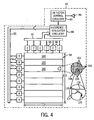
- FIG. 4 is a diagrammatical representation of functional components of digital detector 22.
- detector control circuitry 84 receives DC power from a power source, represented generally at reference numeral 86.
- Detector control circuitry 84 is configured to originate timing and control commands for row and column electronics used to acquire image data during data acquisition phases of operation of the system. Circuitry 84 therefore transmits power and control signals to reference/regulator circuitry 88, and receives digital image pixel data from circuitry 88.
- detector 22 consists of a scintillator that converts X-ray photons received on the detector surface during examinations to lower energy (light) photons.
- An array of photodetectors then converts the light photons to electrical signals which are representative of the number of photons or the intensity of radiation impacting individual pixel regions or picture elements of the detector surface.
- the X-ray photons may be directly converted to electrical signals.
- Readout electronics convert the resulting analog signals to digital values that can be processed, stored, and displayed, such as on device 40 following reconstruction of the image.
- the array of photodetectors is formed of amorphous silicon.
- the array of photodetectors or discrete picture elements is organized in rows and columns, with each discrete picture element consisting of a photodiode and a thin film transistor.
- the cathode of each diode is connected to the source of the transistor, and the anodes of all diodes are connected to a negative bias voltage.
- the gates of the transistors in each row are connected together and the row electrodes are connected to the scanning electronics as described below.
- the drains of the transistors in a column are connected together and the electrode of each column is connected to an individual channel of the readout electronics.
- the detector control circuitry 84 is configured to sample data from the discrete picture elements prior to and during receipt of X-ray radiation. Also, the detector control circuitry 84 is configured to apply a first voltage to transistors of the discrete picture elements prior to receipt of X-ray radiation (e.g., when the detector 22 maintains idle mode). Additionally, the detector control circuitry 84 is configured to sample data from the discrete picture elements in preparation for acquisition of X-ray image data while applying a second voltage, higher than the first voltage, to transistors of the discrete picture elements not then being sampled prior to receipt of X-ray radiation.
- Sampled data collected prior to receipt of the X-ray radiation may be stored by the detector control circuitry 84 for use in reconstruction of a user-viewable image from the X-ray image data. Further, the detector control circuitry 84 is configured to sample data, including X-ray image data, from the discrete picture elements during receipt of X-ray radiation while applying the second voltage to the transistors of the discrete picture elements not then being sampled. Following termination of the receipt of X-ray radiation the detector control circuitry is configured to resume application of the first voltage to the transistors of the discrete picture elements.
- a row bus 90 includes a plurality of conductors for enabling readout from various rows of the detector 22, as well as for disabling rows and applying a charge compensation voltage to selected rows, where desired.
- a column bus 92 includes additional conductors for commanding readout from the columns while the rows are sequentially enabled.
- Row bus 90 is coupled to a series of row drivers 94, each of which commands enabling of a series of rows in the detector 22.
- readout electronics 96 are coupled to column bus 92 for commanding readout of all columns of the detector.
- row drivers 94 and readout electronics 96 are coupled to a detector panel 98 which may be subdivided into a plurality of sections 100. Each section 100 is coupled to one of the row drivers 94, and includes a number of rows. Similarly, each column driver 96 is coupled to a series of columns.
- the photodiode and thin film transistor arrangement mentioned above thereby define a series of pixels or discrete picture elements 102 which are arranged in rows 104 and columns 106.
- the rows and columns define an image matrix 108, having a height 110 and a width 112.
- each picture element 102 is generally defined at a row and column crossing, at which a column electrode 114 crosses a row electrode 116.
- a thin film transistor 118 is provided at each crossing location for each picture element, as is a photodiode 120.
- signals from each photodiode 120 may be accessed via readout electronics 96, and converted to digital signals for subsequent processing and image reconstruction.
- an entire row of picture elements 102 in the array is controlled simultaneously when the scan line attached to the gates of all the transistors 118 of picture elements 102 on that row is activated. Consequently, each of the picture elements 102 in that particular row is connected to a data line, through a switch, which is used by the readout electronics to restore the charge to the photodiode120.
- the readout electronics is converting the measurements from the previous row from an analog voltage to a digital value. Furthermore, the readout electronics may transfer the digital values from rows previous to the acquisition subsystem, which will perform some processing prior to displaying a diagnostic image on a monitor or writing it to film.
- the circuitry used to enable the rows may be referred to in a present context as row enable or field effect transistor (FET) circuitry based upon the use of field effect transistors for such enablement (row driving).
- FET field effect transistor
- the FETs associated with the row enable circuitry described above are placed in an "on” or conducting state for enabling the rows, and are turned “off” or placed in a non-conducting state when the rows are not enabled for readout.
- the particular circuit components used for the row drivers and column readout electronics may vary, and the present invention is not limited to the use of FETs or any particular circuit components.
- the detector 22 is without communication from the source controller 54 and, thus, is without a priori knowledge of the beginning and ending times of an exposure.
- the detector 22 is configured to keep detecting the beginning and ending of the X-ray exposure automatically and form an X-ray image without communication with the detector control device 40.
- the detector 22 is configured to stay in idle power mode and switch to imaging power mode after receiving a command from the detector control device 40. The detector 22 starts detecting the beginning and ending of the X-ray exposure after it is switched into full power mode. This results in a unique workflow dynamic between the X-ray system 12, detector 22, and portable detector controller device 40 as illustrated in FIGS. 5 and 6 .
- FIG. 5 is a perspective view of the two-way interaction between the detector 22 and the portable detector control device 40.
- FIG. 5 illustrates the imaging system 12 with the patient 20 located on the table 28 between the X-ray source 16 and the detector 22.
- imaging system 12 may be a fixed or mobile system.
- FIG. 6 is a flow diagram of a method 124 for workflow between the detector 22 and the portable detector control device 40. To begin, the user turns on the detector 22 (block 126). The detector 22 maintains an idle mode in the on condition. As illustrated in FIG. 5 , the detector 22 is located beneath the subject 20.
- the user Prior to or subsequent to turning on the detector 22, the user inputs patient information or other information (e.g., X-ray technique) related to the imaging (e.g., parameters of the image) into the device 40 (block 128).
- the detector control device 40 may transmit the information to the detector 22, e.g., to form the DICOM compliant data file.
- the DICOM compliant data file is formed in the detector control device 40 so that no need to transfer the patient information to the detector 22.
- the user commands a detector preparation signal from the device 40 to the detector 22 (block 130).
- the detector 22 prepares for the acquisition of X-ray image data. Specifically, the detector 22 switches from the idle mode to imaging power mode and begins scrubbing (i.e., preparing and refreshing the detector circuitry) the panel of the detector 22 to equilibrate the panel. After scrubbing, the detector 22 reads or acquires one or more offset frames prior to exposure. In particular, the detector 22 prepares for exposure by initiating sampling of data from a matrix of detector elements. After preparation, the detector 22 sends to the device 40 the detector ready signal (block 132).
- scrubbing i.e., preparing and refreshing the detector circuitry
- the detector 22 may also provide a visible indication (e.g., flashing light) or an audio indication to indicate the detector is ready.
- the detector control device 40 may provide a visible indication and/or audio indication. The user then commands the X-ray radiation source 16 to perform an X-ray exposure via the source controller 54 coupled to the source 16 (block 134).
- the detector 22 samples data from the matrix of detector elements.
- the detector 22 at least partially processes the X-ray image data (block 136).
- the detector 22 may completely process the X-ray image data. Processing includes determining when the exposure begins and ends based upon comparison of the sampled image data generated by the detector 22. As described in greater detail below, the sampled image data may be collected from one or more frames and combined to generate the reconstructed image. The detector 22 ceases sampling after determining the end of the exposure and after sampling all of the X-ray image data from the frames.
- the detector control device 40 acquires X-ray image data from the detector 22 (block 138) upon which the detector 22 shifts from imaging power mode to idle mode.
- the device 40 at least partially processes the X-ray image data (block 140). In some embodiments, the device 40 completely processes the X-ray image data. Alternatively, the device 40 acquires completely processed X-ray image data from the detector. In other embodiments, neither the detector 22 nor the device 24 completely process the X-ray image data, but send the X-ray image data to the institution image review and storage system for subsequent processing.
- a reconstructed image 122 based upon the X-ray image data is displayed (block 142) on the screen 44 of the device 40.
- the reconstructed image 122 may be displayed on the device 40 while the imaging subject 20 is present in a location wherein the X-ray image data is acquired.
- the user determines whether the image is acceptable (block 144). If the image is not acceptable due to positioning issues, the imaging subject 20 may be repositioned (block 146) for a further exposure. If the image is acceptable, the user may select the interested portion of image, add the "L" and/or "R" position mark, and transmit the processed X-ray image data to the institution image review and storage system (block 148) via the detector 22 and/or device 40.
- the detector 22 Since the detector 22 is without communication of timing signals from the source controller 54 as to performance of the exposure via the source 16, the detector samples data prior to, during, and after the exposure from one or more frames (e.g., offset and imaging frames).
- the length of an X-ray exposure is dependent on numerous factors such as the type of X-ray examination and the size of the imaging subject. In certain instances, the exposure may overlap frames and the sampled X-ray data from at least two imaging frames may need to be combined. However, to do this beginning and ending frames that span at least the duration of the exposure need to be determined.
- FIG. 7 is a diagrammatical representation of sampling and combining X-ray image data when the exposure occurs in a single readout or sampling period.
- FIG. 7 illustrates multiple frames 150 obtained from sampling the matrix of detector elements.
- the frames 150 include offset frames 152 and 154 and imaging frames 156 and 158.
- the offset-corrected X-ray image is generated by combining sampled data from imaging frames 156 and 158 with sampled data (e.g., offset data from offset frame 152) gathered prior to obtaining imaging frame 156.
- Offset frame 152 is acquired prior to the initiation of the exposure.
- Offset frame 154 is acquired after the exposure ends and the frames 150 include no more image data. Neither of the offset frames 152 and 154 includes image data.
- a row average of each frame 150 is obtained.
- the row average reflects the average amount of charge restored to each detector element within a row of detector elements of the detector array to fully charge the detector elements.
- Plot 159 from top to bottom indicates the row average of each row along the frames 150.
- the row average in offset frame 152 and a top portion 160 of imaging frame 156 is negligible, as indicated by portion 162 of the plot 159 since no exposure has occurred and the detector elements remain fully charged.
- the beginning and ending of the exposure is marked by lines 164 and 166, respectively. At line 164, 0 percent of the exposure (i.e., percent of length of total exposure) has occurred, while 100 percent of the exposure has occurred at line 166.
- the row average linearly increases, indicated by portion 168 of the plot 159, as the rows are sequentially read within region 170. More specifically, the row average increases in portion 168 because each subsequent row is exposed to a greater percentage of the exposure and the detector elements within those rows require the restoration of more charge. For example, the first row read after the exposure begins may be subjected to 10 percent of exposure before being read, while the last row read may be subjected to 100 percent of the exposure before being read.
- both imaging frames 156 and 158 include image data indicated by the cross-hatched regions 172 and 174, respectively.
- Flat portion 176 of plot 159 indicates the rows in regions 178 and 180 of imaging frames 156 and 158, respectively, have been exposed to 100 percent of the exposure prior to being read.
- Lines 182 and 184 indicate the beginning and ending of reading rows in region 186 of frame 158 corresponding to region 170 of frame 156.
- the row average linearly decreases as the rows are sequentially read within region 186. More specifically, the row average decreases in region 186 because each subsequent row was exposed to a lesser percent of the exposure after the initial reading of the rows in region 170 of reading frame 156.
- the row average in region 186 reflects image data from residual exposure subsequent to the last reading of the rows.
- the first row read in region 180 of frame 158 may have been subjected to 90 percent of the exposure after the initial reading of the first row in region 170 of frame 156
- the last row read in region 180 may have been subjected to 0 percent of exposure after the initial reading of the last row in region 170 of frame 156.
- Portion 190 of plot 159 indicates the row average 156 in a bottom portion 192 of imaging frame 158 and the offset frame 154 is negligible since the detector elements have been recharged since last being read.
- the beginning and ending of the exposure may be determined as well as the beginning and ending of the imaging data.
- the total number of frames 150 used to make the X-ray image e.g., two, frames 156 and 158 are multiplied time the calculated offset image (e.g., offset frame 152) and subtracted from the X-ray image to form the offset corrected X-ray image.
- FIG. 8 is a diagrammatical representation of sampling and combining X-ray image data when the exposure occurs over two readout or sampling periods. Similar to FIG. 7, FIG. 8 illustrates multiple frames 150 obtained from sampling the matrix of detector elements.
- the frames 150 include offset frames 194 and 196 and imaging frames 198, 200, and 202.
- Offset frame 194 is acquired prior to the initiation of the exposure.
- Offset frame 196 is acquired after the exposure ends and the frames 150 include no more image data. As above, neither of the offset frames 194 and 196 includes image data.
- a row average is obtained for each frame 150 in FIG. 8 .
- Plot 204 from top to bottom indicates the row average of each row along the frames 150.
- the row average in offset frame 194 and a top portion 206 of imaging frame 198 is negligible, as indicated by portion 208 of the plot 204 since no exposure has occurred and the detector elements remain fully charged.
- the beginning and ending of the exposure is marked by lines 210 and 212, respectively. At line 210, 0 percent of the exposure has occurred, while 100 percent of the exposure has occurred at line 212. As illustrated, the exposure spans two sampling periods and, thus, two imaging frames 198 and 200. Similar to FIG. 7, FIG.
- portion 8 includes row averages that linearly increase as indicated by portion 214 of the plot 204 corresponding to regions 216 and 218 of imaging frames 198 and 200.
- flat portion 220 of plot 204 corresponds to region 222 of imaging frame 200 and indicates those rows are exposed to 100 percent of exposure prior to being read.
- Portion 220 is far shorter than portion 176 of FIG. 7 because the exposure in FIG. 8 was longer and spanned more than one imaging frame meaning fewer rows of detector elements were exposed to 100 percent of the exposure prior to being read.
- portion 224 of plot 204 corresponding to regions 226 and 228 of respective imaging frames 200 and 202, includes row averages that linearly decrease.
- Portions 214 and 224 of include lesser slopes than portions 168 and 188 of plot 159 in FIG. 7 due to the longer exposure in FIG. 8 .
- imaging frames 198, 200, and 202 include image data indicated by cross-hatched regions 230, 232, and 234, respectively. As above, by determining the row average, the beginning and ending of the exposure may be determined as well as the beginning and ending of the imaging data.
- the total number of frames 150 used to make the X-ray image e.g., three, frames 198, 200, and 202 are multiplied time the calculated offset image (e.g., offset frame 194) and subtracted from the X-ray image.
- FIG. 9 is a diagrammatical representation of sampling X-ray image data when the exposure occurs after the end of one readout period but before the start of the next readout.
- FIG. 9 illustrates multiple frames 150 obtained from sampling the matrix of detector elements.
- the frames 150 include offset frames 221 and 223 and imaging frame 225.
- Offset frame 221 is acquired prior to the initiation of the exposure.
- Offset frame 223 is acquired after the exposure ends and the frames 150 include no more image data. Neither of the offset frames 221 and 223 includes image data.
- a row average is obtained for each frame in FIG. 9 .
- Plot 227 from top to bottom indicates the row average of each row along the frames 150.
- the row average in offset frame 221 is negligible since no exposure has occurred and the detector elements remain fully charged.
- the beginning and ending of the exposure is marked by lines 229 and 231, respectively.
- portion 233 of plot 227 indicates all of the rows are exposed to 100 percent of the exposure prior to being read.
- the image data indicated by cross-hatched region 235 is located with a single frame 225 and there is no need to combine the imaging frame 225 with any other frame.
- the calculated offset image e.g., offset frame 221 is subtracted from the X-ray image (e.g., frame 225).
- Increases in electronic noise may occur in combining sampled X-ray image data from multiple frames (e.g., at least two imaging frames) to produce X-ray image data capable of being reconstructed into a user-viewable image.
- the X-ray image is obtained by combining three imaging frames with the same offset, for a given pixel p i,j where O i,j represents the offset value
- the electronic noise has zero mean and the 4 values p i , j 1 , p i , j 2 , p i , j 3 , and O i,j are independent of each other
- Another way of reducing the electronic noise is to use different offsets for each of the imaging frames. In that case, the electronic noise of the final image becomes: 2 ⁇ N ⁇ ⁇ .
- a further way to reduce electronic noise is to use the averaged offset for the reading frames. Assume that the offset is obtained by averaging M dark frames (i.e., offset frames). The noise of the offset is 1 M ⁇ ⁇ and the noise of the combined image is N + / M N 2 ⁇ ⁇ .
- Equation (7) is less than equation (5) when M > N.
- the imaging frames combined are greater, then using the same offset or separate offsets may be preferred.
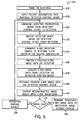
- FIG. 10 is a flow diagram of a method 236 for sampling and combining X-ray image data to produce X-ray image data capable of being reconstructed into a user-viewable image that incorporates the techniques described above.
- the method 236 includes preparing the detector 22 (block 238). Preparation of the detector 22 may include beginning sampling data (e.g., offset data) prior to and independently of initiation of an exposure. Following preparation of the detector 22, the method 236 includes performing an X-ray exposure via the X-ray radiation source 16 (block 240), where the X-ray source is responsive to the source controller 54.
- sampling of X-ray image data occurs via the detector 22 without a priori knowledge of the beginning and ending times of the X-ray exposure (i.e., without communication of timing signals from the source controller 54) (block 242) Indeed, sampling X-ray image data may occur during the X-ray exposure.
- the method 236 further includes determining beginning and ending frames (e.g., imaging frames) of the X-ray image data (block 244). The beginning and ending frames at least span the duration in which the exposure occurred. As mentioned above, the exposure may occur during a single imaging frame, but the X-ray image data may be on multiple imaging frames.
- the beginning and ending frames may contain data sampled during the duration in which the exposure occurred and data sampled outside of the duration in which the exposure occurred.
- the beginning and ending frames are determined by comparison of sampled data of at least the respective and ending frames.
- the beginning and ending frames are determined by identifying a changed in the sampled data values (e.g., row average) indicative of exposure to X-ray radiation.
- the method 236 includes combining the sampled X-ray image data of at least two imaging frames, where at least one of the frames spans the duration in which the exposure occurred, to produce X-ray image data capable of being reconstructed into a user-viewable image (block 246).
- X-ray image data capable of being reconstructed into a user-viewable image may be produced by generating offset corrected image data based upon data sampled from the at least two imaging frames.
- the offset corrected image data is generated by combining sampled data prior to a beginning imaging frame with data sampled from the at least two imaging frames as described above.
- combining the sampled X-ray image data of the at least two imaging frames includes selecting a combination method based upon a noise parameter.
- the calculation of the noise will depend on the number of imaging frames and offset frames (i.e., offset frames) sampled prior to and during the occurrence of the exposure to select the proper equation from those noted above to reduce electronic noise when combining the sampled data from more than one frame.
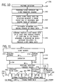
- FIG. 11 a diagrammatical representation of workflow during an acquisition sequence in which both image data and offset data are acquired for producing user-viewable images.
- FIG. 11 includes an acquisition sequence 248 of the detector 22 corresponding to the interaction between the detector 22, portable detector control device 40, the operator or user 38, and the X-ray source 16.
- the detector 22, device 40, and operation of the source 16 are as described above. While the detector 22 is in idle mode, represented by region 250 of the sequence 248, the operator 38 configures the source 16 as indicated by arrow 252. Configuring the source 16 may include setting exposure parameters and the type of exposure. Also, while the detector 22 remains in idle mode, the operator may position the imaging subject and the source 16. Further, the operator 38 enters instructions into device 40, as indicated by arrow 254, and sends instructions 256 to the detector 22 to prepare for exposure.
- the detector 22 Upon receiving the instructions to prepare for acquisition of X-ray image data, the detector 22 enters imaging power mode 258.
- the detector 22 begins by scrubbing the panel, as indicated by region 260 of the acquisition sequence 248, to equilibrate the circuitry on the panel. Then, the detector 22 reads one or more offset frames from the panel (e.g., region 262), upon which the detector 22 sends a detector ready signal 264 to the device 40.
- the device 40 provides a visual indication to indicate the ready state of the detector 22.
- the device 40 provides an audio indication.
- the device 40 provides both video and audio indications.
- the detector 22 provides a visual indication (e.g., flashing LED) to indicate the ready state of the detector 22. In another embodiment, the detector 22 provides an audio indication. Yet in another embodiment, the detector 22 provides both video and audio indications.
- the operator 38 receives the ready signal on the device 40, as indicated by arrow 266. Once the detector 22 is ready, the detector 22 begins continuously sampling or reading frames as indicated by region 268 of the acquisition sequence 248 to detect an exposure. At any time, the operator may initiate the exposure, as indicated by arrow 270, from the source 16. Upon initiation of the exposure, the detector 22 receives the X-ray radiation 272 from the source 16.
- the detector 22 samples the frames to determine the beginning and ending frames that span the exposure (e.g., frames 274 and 276). After termination of the exposure, the detector 22 may process the acquired image data and send a preview of a reconstructed image, indicated by arrow 278, to the device 40 for viewing by the operator 38. Alternatively, the data may be sent to the device 40 for further processing and the generation of the reconstructed image. After the exposure ends, the detector 22 reverts back to idle mode as indicated by region 280 of the acquisition sequence 248.
- the detector 22 shifts from an idle mode to an imaging power mode.
- the detector 22 In the imaging power mode, the detector 22 continuously reads the panel, since the detector 22 lacks a priori knowledge (or data) of when the exposure may occur. Thus, reading or sampling of data from the panel occurs during the exposure.
- Transistors e.g., FETs
- Transistors e.g., FETs
- leakage may occur from those transistors of discrete picture elements not then being sampled (i.e., transistors are in a non-conducting state when the rows are not enabled for readout).
- V off to maintain the transistors not then being sampled in a non-conductive state may reduce FET leakage. However, reduction of the leakage may not persist if the transistors are biased for a while due to bias age.
- FIGS. 12 and 13 illustrate embodiments of techniques to overcome these issues.
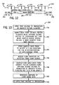
- FIG. 12 is a diagrammatical representation of an acquisition sequence 282 in which different voltages are applied to reduce transistor leakage while sampling image data, particularly during exposure.
- the acquisition signal 282 of FIG. 12 is the same as acquisition signal 248 described in FIG. 11 .
- the acquisition signal 282 includes regions 250 and 280 where the detector 22 maintains an idle mode.
- the acquisition signal 282 includes regions where the detector 22 scrubs the panel (e.g., region 260) and periods of sampling or reading the panel (e.g., regions 262 and 268).
- the detector 22 applies a first voltage 284 (e.g., less negativeV off ) to the transistors of the discrete picture elements when the detector 22 maintains an idle mode (e.g., regions 250 and 280). Thus, the detector 22 applies the first voltage 284 to the transistors of the discrete picture elements prior to receipt of X-ray radiation (e.g., region 250).
- the detector 22 applies a second voltage 286 (e.g., more negativeV off ) to the transistors of the discrete picture elements not then being sampled when the detector 22 shifts to imaging power mode 258 (e.g., regions 260, 262, and 268) and begins sampling data from the discrete picture elements.
- the first voltage 284 may be applied, instead of the second voltage 286, while scrubbing the panel (i.e., region 260).
- the application of the second voltage 286 to the transistors of the discrete picture elements not then being sampled also occurs during receipt of X-ray radiation by the detector 22.
- the detector 22 Upon termination of sampling X-ray data from the discrete picture elements (e.g., region 280), the detector 22 reapplies the first voltage 284 to the transistors of the discrete picture elements after termination of the receipt of X-ray radiation by the detector 22.
- the second voltage 286 is more negative than the first voltage 284.
- the second voltage 286 may be at least approximately 1.3 times the first voltage 284.
- the first voltage 284 may be equal to or less negative than approximately -11 volts.
- the second voltage 286 may be equal to or more negative than approximately - 15 volts.
- the first and second voltages 284 and 286 maintain the transistors in a non-conductive state. By maintaining the second voltage 286 only during the imaging power mode 258 and shifting to the first voltage 284 in idle mode (e.g., regions 250 and 280), the transistor leakage may be reduced while also avoiding bias age.
- FIG. 13 is a flow diagram of a method 288 for sampling data from the detector prior to and after an X-ray exposure while applying different voltages to reduce transistor leakage.
- the method 288 includes applying the first voltage 284 to transistors of the discrete picture elements (e.g., when detector 22 maintains idle mode) (block 290). While preparing for the acquisition of X-ray image data, the method 288 includes sampling data from the discrete picture elements while applying the second voltage 286 to the transistors of the discrete picture elements not then being sampled, where the second voltage 286 is more negative than the first voltage 284 (block 292).
- the detector 22 may store sampled data prior to receipt of the X-ray radiation for use in reconstruction of a user-viewable image from the X-ray image data (block 294).
- the method 288 includes receiving X-ray radiation on the detector 22 from the X-ray source 16 (block 296). After exposure, sampling of X-ray image data from the discrete picture elements occurs while applying the second voltage 286 to the transistors of the discrete picture elements not then being sampled (block 298). Sampling of data from the discrete picture elements also occurs during receipt of X-ray radiation, while applying the second voltage 286 to the transistors of the discrete picture elements not then being sampled.
- the detector 22 After termination of receipt of X-ray radiation, the detector 22 terminates sampling of X-ray image data from the discrete picture elements (block 300) and re-applies the first voltage 284 to the transistors of the discrete picture elements (block 302), for example, during the transition to idle mode.
- transistor leakage may be reduced while also avoiding bias age by maintaining the second voltage 286 only during the imaging power mode and shifting to the first voltage 284 in idle mode.
- the embodiments include providing methods and systems to allow for the retrofitting of conventional X-ray systems by replacing cassettes with a digital X-ray detector.
- the digital X-ray detector does not communicate with the X-ray imaging system. Instead, the detector communicates with a portable detector control device to receive instructions. Since the detector does not communicate with the X-ray system, the detector lacks data indicating the timing signals for an X-ray exposure. Thus, the detector in preparation for and during an exposure may continuously read the panel of the detector.
- the detector may include techniques to determine the beginning and ending of the exposure and imaging data, gather and combine X-ray image data from multiple frames, while reducing factors that may adversely affect the quality of the image (e.g., electrical noise and transistor leakage).
Landscapes
- Health & Medical Sciences (AREA)
- Life Sciences & Earth Sciences (AREA)
- Engineering & Computer Science (AREA)
- Medical Informatics (AREA)
- Physics & Mathematics (AREA)
- Pathology (AREA)
- Public Health (AREA)
- Biophysics (AREA)
- Nuclear Medicine, Radiotherapy & Molecular Imaging (AREA)
- Optics & Photonics (AREA)
- Veterinary Medicine (AREA)
- Radiology & Medical Imaging (AREA)
- Biomedical Technology (AREA)
- Heart & Thoracic Surgery (AREA)
- Molecular Biology (AREA)
- Surgery (AREA)
- Animal Behavior & Ethology (AREA)
- General Health & Medical Sciences (AREA)
- High Energy & Nuclear Physics (AREA)
- Mathematical Physics (AREA)
- Computer Networks & Wireless Communication (AREA)
- Computer Vision & Pattern Recognition (AREA)
- Apparatus For Radiation Diagnosis (AREA)
Description
- The subject matter disclosed herein relates to X-ray imaging systems and more particularly to X-ray imaging system using digital detectors.
- The advent of digital X-ray detectors has brought enhanced workflow and high image quality to medical imaging. However, many of the earlier radiographic imaging systems employ conventional X-ray imaging using film and/or computed radiography. In order to obtain images from these systems, the imaging medium must be transported and processed after each exposure, resulting in a time delay in obtaining the desired images. Digital radiography provides an alternative that allows the acquisition of image data and reconstructed images on the spot for quicker viewing and diagnosis. However, the cost of replacing the earlier conventional radiographic imagining systems with digital radiographic imaging systems may be imposing to a hospital or tertiary care medical center. Hence, the need to retrofit the earlier radiographic imaging systems for digital radiography in a cost effective manner involving as few components of the systems as possible.
- In accordance with one embodiment, an X-ray imaging method includes performing an X-ray exposure via an X-ray radiation source responsive to a source controller. The method also includes sampling X-ray image data via a digital detector without communication of timing signals from the source controller. The method further includes combining the sampled X-ray image data of at least one imaging frame or two or more imaging frames with at least one of the frames spanning a duration in which the exposure occurred, to produce X-ray image data capable of being reconstructed into a user-viewable image.
- In accordance with another embodiment, an X-ray imaging method includes performing an X-ray exposure via an X-ray radiation source. The method also includes sampling X-ray image data via a digital detector without a priori knowledge of beginning and ending times of the X-ray exposure. The method further includes determining beginning and ending frames of the X-ray image data. The method yet further includes combining the sampled X-ray image data of at least one imaging frame or two or more imaging frames with at least one of the frames spanning a duration in which the exposure occurred, to produce X-ray image data capable of being reconstructed into a user-viewable image.
- In accordance with a further embodiment, the X-ray imaging system includes an X-ray radiation source, a source controller coupled to the source and configured to command X-ray emission of X-rays for image exposures, and a digital X-ray detector configured to sample X-ray image data without communication from the source controller. The system also includes a portable detector control device configured to communicate instructions to the detector for acquisition of the X-ray image data and to receive the X-ray image data from the detector for processing and preview. At least one of the detector, the portable detector control device, and a processing system in communication with the detector and/or the portable detector control device is configured to combine the sampled X-ray image data of at least one imaging frame or two or more imaging frames with at least one of the frames spanning a duration in which the exposure occurred, to produce X-ray image data capable of being reconstructed into a user-viewable image.
- These and other features, aspects, and advantages of the present invention will become better understood when the following detailed description is read with reference to the accompanying drawings in which like characters represent like parts throughout the drawings, wherein:
-
FIG. 1 is a perspective view of an exemplary fixed X-ray system, equipped in accordance with aspects of the present technique; -
FIG. 2 is a perspective view of an exemplary mobile X-ray system, equipped in accordance with aspects of the present technique; -
FIG. 3 is a diagrammatical overview of the X-ray system inFIGS. 1 and2 ; -
FIG. 4 is a diagrammatical representation of functional components in a detector of the system ofFIGS. 1-3 ; -
FIG. 5 is a perspective view of the two-way interaction between the detector and a portable detector control device, in accordance with aspects of the present technique; -
FIG. 6 is a flow diagram of a method for workflow between the detector and the portable detector control device, in accordance with aspects of the present technique; -
FIG. 7 is a diagrammatical representation of sampling X-ray image data from two imaging frames, in accordance with aspects of the present technique; -
FIG. 8 is a diagrammatical representation of sampling and combining X-ray image data from three imaging frames, in accordance with aspects of the present technique; -
FIG. 9 is a diagrammatical representation of sampling and combining X-ray image data from one imaging frame, in accordance with aspects of the present technique; -
FIG. 10 is a flow diagram of a method for sampling and combining X-ray image data to produce X-ray image data capable of being reconstructed into a user-viewable image, in accordance with aspects of the present technique; -
FIG. 11 is a diagrammatical representation of workflow during an acquisition sequence in which both image data and offset data are acquired for producing user-viewable images, in accordance with aspects of the present technique; -
FIG. 12 is a diagrammatical representation of an acquisition sequence in which different voltages are applied to reduce transistor leakage while sampling image data, in accordance with aspects of the present technique; and -
FIG. 13 is a flow diagram of a method for sampling data from the detector prior to and after an X-ray exposure while applying different voltages to reduce transistor leakage, in accordance with aspects of the present technique. - Referring generally to
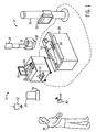
FIG. 1 , an X-ray system is represented, referenced generally byreference numeral 10. In the illustrated embodiment, theX-ray system 10, as adapted, is a digital X-ray system. The X-raysystem 10 is designed both to acquire image data and to process the image data for display in accordance with the present technique. Throughout the following discussion, however, while basic and background information is provided on the digital X-ray system used in medical diagnostic applications, it should be born in mind that aspects of the present techniques may be applied to digital detectors, including X-ray detectors, used in different settings (e.g., projection X-ray, computed tomography imaging, tomosynthesis imaging, etc.) and for different purposes (e.g., parcel, baggage, vehicle and part inspection, etc.). - In the embodiment illustrated in
FIG. 1 , theX-ray system 10 includes animaging system 12. Theimaging system 12 may be a conventional analog imaging system, retrofitted for digital image data acquisition and processing as described below. In one embodiment, theimaging system 12 may be a stationary system disposed in a fixed X-ray imaging room, such as that generally depicted in and described below with respect toFIG. 1 . It will be appreciated, however, that the presently disclosed techniques may also be employed with other imaging systems, including mobile X-ray units and systems in other embodiments. Theimaging system 12 includes an overheadtube support arm 14 for positioning aradiation source 16, such as an X-ray tube, and acollimator 18 with respect to apatient 20 and adetector 22. Thedetector 22 includes a digital X-ray detector. In some embodiments, thedetector 22 may be selected from a plurality ofdetectors 22, represented bydetector 24, from a dock 26 (e.g., charging dock). Eachdetector 22 of the plurality ofdetectors 22 may be labeled and designed for a particular type of imaging (e.g., fluoroscopic and radiographic imaging). Thedetector 22 is configured to acquire X-ray image data without communication from a controller of theX-ray radiation source 16. In other words, thedetector 22 is without communication of timing signals from the controller of thesource 16 as to an X-ray exposure. As a result, in preparation for acquiring X-ray image data thedetector 22 is configured to continuously sample data prior to and during an X-ray exposure. Also, thedetector 22 is configured to combine multiple frames that include imaging data to generate X-ray images. In addition, thedetector 22 is configured to at least partially process X-ray image data. - In one embodiment, the
imaging system 12 may be used in consort with one or both of a patient table 28 and a wall stand 30 to facilitate image acquisition. Particularly, the table 28 and thewall stand 30 may be configured to receivedetector 22. For instance,detector 22 may be placed on an upper, lower or intermediate surface of the table 28, and the patient 20 (more specifically, an anatomy of interest of the patient 20) may be positioned on the table 28 between thedetector 22 and theradiation source 16. Also, thewall stand 30 may include areceiving structure 32 also adapted to receive thedetector 22, and thepatient 20 may be positioned adjacent thewall stand 30 to enable the image data to be acquired via thedetector 22. Thereceiving structure 32 may be moved vertically along thewall stand 30. - Also depicted in
FIG. 1 , theimaging system 12 includes aworkstation 34,display 36, andprinter 37. In one embodiment, theworkstation 34 may include or provide the functionality of theimaging system 12 such that auser 38, by interacting with theworkstation 34 may control operation of thesource 16 anddetector 22. In other embodiments, the functions of theimaging system 12 may be decentralized, such that some functions of theimaging system 12 are performed at the workstation 34 (e.g., controlling operation of thesource 16, while other functions (e.g., controlling operation of the detector 22) are performed by another component of theX-ray system 10, such as a portabledetector control device 40. The portabledetector control device 40 may include a personal digital assistant (PDA), palmtop computer, laptop computer, smart telephone, tablet computer such as an iPad™, or any suitable general purpose or dedicated portable interface device. The portabledetector control device 40 is configured to be held by theuser 38 and to communicate wirelessly with thedetector 22. It is noted that thedetector 22 and portabledetector control device 40 may utilize any suitable wireless communication protocol, such as an IEEE 802.15.4 protocol, an ultra wideband (UWB) communication standard, a Bluetooth communication standard, or any IEEE 802.11 communication standard. Alternatively, the portable detector control device may be configured to be tethered or detachably tethered to thedetector 22 to communicate via a wired connection. - The portable
detector control device 40 is also configured to communicate instructions (e.g., detector operating mode) to thedetector 22 for the acquisition of X-ray image data. In turn, thedetector 22 is configured to prepare for an X-ray exposure in response to instructions from the portabledetector control device 40, and to transmit a detector ready signal to thedevice 40 indicating that thedetector 22 is prepared to receive the X-ray exposure. Thedevice 40 may also be configured to communicate patient information or X-ray technique information to thedetector 22. Similar to thedetector 22, thedevice 40 may be without communication from the controller of the X-ray source16. Further, the portabledetector control device 40 is configured to receive X-ray image data from thedetector 22 for processing and image reconstruction. Indeed, both thedetector 22 and the portabledetector control device 40 are configured to at least partially process the X-ray image data. However, in certain embodiments, thedetector 22 and/or the portabledetector control device 40 are configured to fully process the X-ray image data. Also, thedetector 22 and/or thedevice 40 is configured to generate a DICOM compliant data file based upon the X-ray image data, patient information, and other information. Further, thedetector 22 and/or thedevice 40 is configured to wirelessly transmit (or via a wired connection) processed X-ray image data (e.g., partially or fully processed X-ray image data) to an institution image review and storage system over anetwork 42. The institution image review and storage system may include a hospital information system (HIS), a radiology information system (RIS), and/or picture archiving communication system (PACS). In some embodiments, the institution image review and storage system may process the X-ray image data. In one embodiment, theworkstation 34 may be configured to function as a server of instructions and/or content on anetwork 42 of the medical facility. Thedetector 22 and/ordevice 40 are also configured to transmit, via a wired or wireless connection, processed X-ray images to theprinter 37 to generate a copy of the image. - The portable
detector control device 40 includes a user-viewable screen 44 and is configured to display patient data and reconstructed X-ray images based upon X-ray image data on thescreen 44. Thescreen 44 may include a touch-screen and/or input device (e.g., keyboard) configured to input data (e.g., patient data) and/or commands (e.g., to the detector). For example, thedevice 40 may be used to input patient information and other imaging related information (e.g., type ofsource 16, imaging parameters, etc.) to form a DICOM image header. In one embodiment, the patient information may be transferred from a patient database via a wireless or wired connection from the network or theworkstation 34 to thedevice 40. Thedetector 22 and/or device may incorporate the information for the image header with the X-ray image to generate the DICOM compliant data file. Also, thedevice 40 may be used to navigate X-ray images displayed on thescreen 44. Further, thedevice 40 may be used to modify the X-ray images, for example, by adding position markers (e.g., "L"/ "R" for left and right, respectively) onto the image. In one embodiment, metal markers may be placed on thedetector 22 to generate position markers. - In one embodiment, the
imaging system 12 may be a stationary system disposed in a fixed X-ray imaging room, such as that generally depicted in and described above with respect toFIG. 1 . It will be appreciated, however, that the presently disclosed techniques may also be employed with other imaging systems, including mobile X-ray units and systems, in other embodiments. - For instance, as illustrated in the X-ray system of
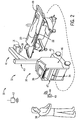
FIG. 2 , theimaging system 12 may be moved to a patient recovery room, an emergency room, a surgical room, or any other space to enable imaging of thepatient 20 without requiring transport of the patient 20 to a dedicated (i.e., fixed) X-ray imaging room. Theimaging system 12 includes a mobileX-ray base station 39 anddetector 22. Similar to above, theimaging system 12 may be a conventional analog imaging system, retrofitted for digital image data acquisition and processing. In one embodiment, asupport arm 41 may be vertically moved along asupport column 43 to facilitate positioning of theradiation source 16 andcollimator 18 with respect to thepatient 20. Further, one or both of thesupport arm 41 andsupport column 43 may also be configured to allow rotation of theradiation source 16 about an axis. Further, theX-ray base station 39 has a wheeledbase 45 for movement of thestation 39. Systemselectronic circuitry 46 with abase unit 47 both provides and controls power to theX-ray source 16 and thewheeled base 45 in theimaging system 12. Thebase unit 47 also has theoperator workstation 34 anddisplay 36 that enables theuser 38 to operate theX-ray system 10. Theoperator workstation 34 may include buttons, switches, or the like to facilitate operation of theX-ray source 16. Similar to theX-ray system 10 inFIG. 1 , thesystem 10 includes theportable control device 40. Thedetector 22 andportable control device 40 are as described above. In the X-ray system, thepatient 20 may be located on a bed 49 (or gurney, table or any other support) between theX-ray source 16 and thedetector 22 and subjected to X-rays that pass through thepatient 20 and are received by thedetector 22. -
FIG. 3 is a diagrammatical overview of theX-ray system 10 inFIGS. 1 and2 illustrating the components of thesystem 10 in more detail. Theimaging system 10 includes theX-ray radiation source 16 positioned adjacent to acollimator 18.Collimator 18 permits a stream ofradiation 48 to pass into a region in which a subject 20, such as ahuman patient 20, is positioned. A portion of theradiation 50 passes through or around the subject 20 and impacts thedigital X-ray detector 22. As described more fully below,detector 22 converts the X-ray photons received on its surface to lower energy photons, and subsequently to electric signals which are acquired and processed to reconstruct an image of the features within the subject 20. - The
source 16 is coupled to apower supply 52 which furnishes power for examination sequences. Thesource 16 andpower supply 52 are coupled to asource controller 54 configured to command X-ray emission of X-rays for image exposures. As mentioned above, thedetector 22 is configured to acquire X-ray image data without communication from thesource controller 54. Instead, thedetector 22 is responsive to the portabledetector control device 40 configured to communicate instructions thedetector 22 for acquisition of the X-ray image data. In addition, the portabledetector control device 40 is configured to receive the X-ray image data from thedetector 22 for processing and imaging reconstruction. - The
detector 22 includes awireless communication interface 56 for wireless communication with thedevice 40, as well as awired communication interface 58, for communicating with thedevice 40 when it is tethered to thedetector 22. Thedetector 22 and the device may also be in communication with the institution image review and storage system over thenetwork 42 via a wired or wireless connection. As mentioned above, the institution image review and storage system may includePACS 60,RIS 62, and HIS 64. It is noted that thewireless communication interface 56 may utilize any suitable wireless communication protocol, such as an ultra wideband (UWB) communication standard, a Bluetooth communication standard, or any 802.11 communication standard. Moreover,detector 22 is coupled to adetector controller 66 which coordinates the control of the various detector functions. For example,detector controller 66 may execute various signal processing and filtration functions, such as for initial adjustment of dynamic ranges, interleaving of digital image data, and so forth. Thedetector controller 66 is responsive to signals from thedevice 40. Thedetector controller 66 is linked to aprocessor 68. Theprocessor 68, thedetector controller 66, and all of the circuitry receive power from apower supply 70. Thepower supply 70 may include one or more batteries. - Also, the
processor 68 is linked todetector interface circuitry 72. Thedetector 22 converts X-ray photons received on its surface to lower energy photons. Thedetector 22 includes adetector array 74 that includes an array of photodetectors to convert the light photons to electrical signals. Alternatively, thedetector 22 may convert the X-ray photons directly to electrical signals. These electrical signals are converted to digital values by thedetector interface circuitry 72 which provides the values to theprocessor 68 to be converted to imaging data and sent to thedevice 40 to reconstruct an image of the features within the subject 20. In one embodiment, thedetector 22 may at least partially process or fully process the imaging data. Alternatively, the imaging data may be sent from thedetector 22 to a server to process the imaging data. - The
processor 68 is also linked to anillumination circuit 76. Thedetector controller 66, in response to a signal received from thedevice 40, may send a signal to theprocessor 68 to signal theillumination circuit 76 to illuminate a light 78 to indicate thedetector 22 is prepared to receive an X-ray exposure in response to the signal. Indeed, in response to a signal from thedevice 40, thedetector 22 may be turned on or awoken from an idle state. Alternatively, thedetector 22 may be turned on directly or awoken from an idle state by the user (e.g., pressing an on/off button located on the detector 22). - Further, the processor is linked to a
memory 80. Thememory 80 may store various configuration parameters, calibration files, and detector identification data. In addition, thememory 80 may store patient information received from thedevice 40 to be combined with the image data to generate a DICOM compliant data file. Further, thememory 80 may store sampled data gathered during the imaging mode as well as X-ray images. As mentioned above, in some embodiments, thedevice 40 may conduct the image processing and incorporate a DICOM header to generate a DICOM compliant data file. -
FIG. 4 is a diagrammatical representation of functional components ofdigital detector 22. As illustrated, detector control circuitry 84 receives DC power from a power source, represented generally atreference numeral 86. Detector control circuitry 84 is configured to originate timing and control commands for row and column electronics used to acquire image data during data acquisition phases of operation of the system. Circuitry 84 therefore transmits power and control signals to reference/regulator circuitry 88, and receives digital image pixel data fromcircuitry 88. - In a present embodiment,
detector 22 consists of a scintillator that converts X-ray photons received on the detector surface during examinations to lower energy (light) photons. An array of photodetectors then converts the light photons to electrical signals which are representative of the number of photons or the intensity of radiation impacting individual pixel regions or picture elements of the detector surface. In certain presently contemplated, the X-ray photons may be directly converted to electrical signals. Readout electronics convert the resulting analog signals to digital values that can be processed, stored, and displayed, such as ondevice 40 following reconstruction of the image. In a present form, the array of photodetectors is formed of amorphous silicon. The array of photodetectors or discrete picture elements is organized in rows and columns, with each discrete picture element consisting of a photodiode and a thin film transistor. The cathode of each diode is connected to the source of the transistor, and the anodes of all diodes are connected to a negative bias voltage. The gates of the transistors in each row are connected together and the row electrodes are connected to the scanning electronics as described below. The drains of the transistors in a column are connected together and the electrode of each column is connected to an individual channel of the readout electronics. - As described in greater detail below, the detector control circuitry 84 is configured to sample data from the discrete picture elements prior to and during receipt of X-ray radiation. Also, the detector control circuitry 84 is configured to apply a first voltage to transistors of the discrete picture elements prior to receipt of X-ray radiation (e.g., when the
detector 22 maintains idle mode). Additionally, the detector control circuitry 84 is configured to sample data from the discrete picture elements in preparation for acquisition of X-ray image data while applying a second voltage, higher than the first voltage, to transistors of the discrete picture elements not then being sampled prior to receipt of X-ray radiation. Sampled data collected prior to receipt of the X-ray radiation may be stored by the detector control circuitry 84 for use in reconstruction of a user-viewable image from the X-ray image data. Further, the detector control circuitry 84 is configured to sample data, including X-ray image data, from the discrete picture elements during receipt of X-ray radiation while applying the second voltage to the transistors of the discrete picture elements not then being sampled. Following termination of the receipt of X-ray radiation the detector control circuitry is configured to resume application of the first voltage to the transistors of the discrete picture elements. - Turning back to the embodiment illustrated in
FIG. 4 , by way of example, arow bus 90 includes a plurality of conductors for enabling readout from various rows of thedetector 22, as well as for disabling rows and applying a charge compensation voltage to selected rows, where desired. Acolumn bus 92 includes additional conductors for commanding readout from the columns while the rows are sequentially enabled.Row bus 90 is coupled to a series ofrow drivers 94, each of which commands enabling of a series of rows in thedetector 22. Similarly,readout electronics 96 are coupled tocolumn bus 92 for commanding readout of all columns of the detector. - In the illustrated embodiment,
row drivers 94 andreadout electronics 96 are coupled to adetector panel 98 which may be subdivided into a plurality ofsections 100. Eachsection 100 is coupled to one of therow drivers 94, and includes a number of rows. Similarly, eachcolumn driver 96 is coupled to a series of columns. The photodiode and thin film transistor arrangement mentioned above thereby define a series of pixels ordiscrete picture elements 102 which are arranged inrows 104 and columns 106. The rows and columns define an image matrix 108, having aheight 110 and a width 112. - As also illustrated in
FIG. 4 , eachpicture element 102 is generally defined at a row and column crossing, at which acolumn electrode 114 crosses arow electrode 116. As mentioned above, athin film transistor 118 is provided at each crossing location for each picture element, as is aphotodiode 120. As each row is enabled byrow drivers 94, signals from eachphotodiode 120 may be accessed viareadout electronics 96, and converted to digital signals for subsequent processing and image reconstruction. Thus, an entire row ofpicture elements 102 in the array is controlled simultaneously when the scan line attached to the gates of all thetransistors 118 ofpicture elements 102 on that row is activated. Consequently, each of thepicture elements 102 in that particular row is connected to a data line, through a switch, which is used by the readout electronics to restore the charge to the photodiode120. - It should be noted that in certain systems, as the charge is restored to all the
picture elements 102 in a row simultaneously by each of the associated dedicated readout channels, the readout electronics is converting the measurements from the previous row from an analog voltage to a digital value. Furthermore, the readout electronics may transfer the digital values from rows previous to the acquisition subsystem, which will perform some processing prior to displaying a diagnostic image on a monitor or writing it to film. - The circuitry used to enable the rows may be referred to in a present context as row enable or field effect transistor (FET) circuitry based upon the use of field effect transistors for such enablement (row driving). The FETs associated with the row enable circuitry described above are placed in an "on" or conducting state for enabling the rows, and are turned "off" or placed in a non-conducting state when the rows are not enabled for readout. Despite such language, it should be noted that the particular circuit components used for the row drivers and column readout electronics may vary, and the present invention is not limited to the use of FETs or any particular circuit components.
- As mentioned above, the
detector 22 is without communication from thesource controller 54 and, thus, is without a priori knowledge of the beginning and ending times of an exposure. In one embodiment, the detector 22is configured to keep detecting the beginning and ending of the X-ray exposure automatically and form an X-ray image without communication with thedetector control device 40. In another embodiment, thedetector 22 is configured to stay in idle power mode and switch to imaging power mode after receiving a command from thedetector control device 40. Thedetector 22 starts detecting the beginning and ending of the X-ray exposure after it is switched into full power mode. This results in a unique workflow dynamic between theX-ray system 12,detector 22, and portabledetector controller device 40 as illustrated inFIGS. 5 and6 .FIG. 5 is a perspective view of the two-way interaction between thedetector 22 and the portabledetector control device 40.FIG. 5 illustrates theimaging system 12 with the patient 20 located on the table 28 between theX-ray source 16 and thedetector 22. Here again,imaging system 12 may be a fixed or mobile system.FIG. 6 is a flow diagram of amethod 124 for workflow between thedetector 22 and the portabledetector control device 40. To begin, the user turns on the detector 22 (block 126). Thedetector 22 maintains an idle mode in the on condition. As illustrated inFIG. 5 , thedetector 22 is located beneath the subject 20. Prior to or subsequent to turning on thedetector 22, the user inputs patient information or other information (e.g., X-ray technique) related to the imaging (e.g., parameters of the image) into the device 40 (block 128). In some embodiments, thedetector control device 40 may transmit the information to thedetector 22, e.g., to form the DICOM compliant data file. In some other embodiments, the DICOM compliant data file is formed in thedetector control device 40 so that no need to transfer the patient information to thedetector 22. - The user commands a detector preparation signal from the
device 40 to the detector 22 (block 130). Once thedetector 22 receives the command to prepare from thedevice 40, thedetector 22 prepares for the acquisition of X-ray image data. Specifically, thedetector 22 switches from the idle mode to imaging power mode and begins scrubbing (i.e., preparing and refreshing the detector circuitry) the panel of thedetector 22 to equilibrate the panel. After scrubbing, thedetector 22 reads or acquires one or more offset frames prior to exposure. In particular, thedetector 22 prepares for exposure by initiating sampling of data from a matrix of detector elements. After preparation, thedetector 22 sends to thedevice 40 the detector ready signal (block 132). In one embodiment, thedetector 22 may also provide a visible indication (e.g., flashing light) or an audio indication to indicate the detector is ready. In another embodiment, thedetector control device 40 may provide a visible indication and/or audio indication. The user then commands theX-ray radiation source 16 to perform an X-ray exposure via thesource controller 54 coupled to the source 16 (block 134). - During and after the exposure, the
detector 22 samples data from the matrix of detector elements. In certain embodiments, thedetector 22 at least partially processes the X-ray image data (block 136). Alternatively, thedetector 22 may completely process the X-ray image data. Processing includes determining when the exposure begins and ends based upon comparison of the sampled image data generated by thedetector 22. As described in greater detail below, the sampled image data may be collected from one or more frames and combined to generate the reconstructed image. Thedetector 22 ceases sampling after determining the end of the exposure and after sampling all of the X-ray image data from the frames. After and during the exposure, thedetector control device 40 acquires X-ray image data from the detector 22 (block 138) upon which thedetector 22 shifts from imaging power mode to idle mode. In certain embodiments, thedevice 40 at least partially processes the X-ray image data (block 140). In some embodiments, thedevice 40 completely processes the X-ray image data. Alternatively, thedevice 40 acquires completely processed X-ray image data from the detector. In other embodiments, neither thedetector 22 nor thedevice 24 completely process the X-ray image data, but send the X-ray image data to the institution image review and storage system for subsequent processing. - As seen in
FIG. 5 , areconstructed image 122 based upon the X-ray image data is displayed (block 142) on thescreen 44 of thedevice 40. Indeed, thereconstructed image 122 may be displayed on thedevice 40 while theimaging subject 20 is present in a location wherein the X-ray image data is acquired. After displaying theimage 122 on thedevice 40, the user determines whether the image is acceptable (block 144). If the image is not acceptable due to positioning issues, theimaging subject 20 may be repositioned (block 146) for a further exposure. If the image is acceptable, the user may select the interested portion of image, add the "L" and/or "R" position mark, and transmit the processed X-ray image data to the institution image review and storage system (block 148) via thedetector 22 and/ordevice 40. - Since the
detector 22 is without communication of timing signals from thesource controller 54 as to performance of the exposure via thesource 16, the detector samples data prior to, during, and after the exposure from one or more frames (e.g., offset and imaging frames). The length of an X-ray exposure is dependent on numerous factors such as the type of X-ray examination and the size of the imaging subject. In certain instances, the exposure may overlap frames and the sampled X-ray data from at least two imaging frames may need to be combined. However, to do this beginning and ending frames that span at least the duration of the exposure need to be determined. -
FIG. 7 is a diagrammatical representation of sampling and combining X-ray image data when the exposure occurs in a single readout or sampling period.FIG. 7 illustratesmultiple frames 150 obtained from sampling the matrix of detector elements. Theframes 150 include offsetframes frames imaging frame 156. Offsetframe 152 is acquired prior to the initiation of the exposure. Offsetframe 154 is acquired after the exposure ends and theframes 150 include no more image data. Neither of the offsetframes - To determine the beginning and ending of the exposure and the imaging data, a row average of each
frame 150 is obtained. The row average reflects the average amount of charge restored to each detector element within a row of detector elements of the detector array to fully charge the detector elements. Plot 159 from top to bottom indicates the row average of each row along theframes 150. The row average in offsetframe 152 and atop portion 160 ofimaging frame 156 is negligible, as indicated byportion 162 of theplot 159 since no exposure has occurred and the detector elements remain fully charged. The beginning and ending of the exposure is marked bylines line 164, 0 percent of the exposure (i.e., percent of length of total exposure) has occurred, while 100 percent of the exposure has occurred atline 166. Correspondingly, during the exposure, the row average linearly increases, indicated byportion 168 of theplot 159, as the rows are sequentially read withinregion 170. More specifically, the row average increases inportion 168 because each subsequent row is exposed to a greater percentage of the exposure and the detector elements within those rows require the restoration of more charge. For example, the first row read after the exposure begins may be subjected to 10 percent of exposure before being read, while the last row read may be subjected to 100 percent of the exposure before being read. - Since the exposure ended within a single sampling or reading period, both imaging frames 156 and 158 include image data indicated by the
cross-hatched regions Flat portion 176 ofplot 159 indicates the rows inregions Lines region 186 offrame 158 corresponding toregion 170 offrame 156. As indicated byportion 188 of theplot 159, the row average linearly decreases as the rows are sequentially read withinregion 186. More specifically, the row average decreases inregion 186 because each subsequent row was exposed to a lesser percent of the exposure after the initial reading of the rows inregion 170 ofreading frame 156. In other words, the row average inregion 186 reflects image data from residual exposure subsequent to the last reading of the rows. For example, the first row read inregion 180 offrame 158 may have been subjected to 90 percent of the exposure after the initial reading of the first row inregion 170 offrame 156, while the last row read inregion 180 may have been subjected to 0 percent of exposure after the initial reading of the last row inregion 170 offrame 156.Portion 190 ofplot 159 indicates the row average 156 in abottom portion 192 ofimaging frame 158 and the offsetframe 154 is negligible since the detector elements have been recharged since last being read. As a result, by determining the row average, the beginning and ending of the exposure may be determined as well as the beginning and ending of the imaging data. - To obtain the X-ray image all of the
frames 150 including image data (e.g., frames 156 and 158) are combined (i.e., added). To obtain the offset-corrected X-ray image, the total number offrames 150 used to make the X-ray image (e.g., two,frames 156 and 158) are multiplied time the calculated offset image (e.g., offset frame 152) and subtracted from the X-ray image to form the offset corrected X-ray image. - The row average may also be used when the exposure spans more than one reading or sampling period.
FIG. 8 is a diagrammatical representation of sampling and combining X-ray image data when the exposure occurs over two readout or sampling periods. Similar toFIG. 7, FIG. 8 illustratesmultiple frames 150 obtained from sampling the matrix of detector elements. Theframes 150 include offsetframes frame 194 is acquired prior to the initiation of the exposure. Offsetframe 196 is acquired after the exposure ends and theframes 150 include no more image data. As above, neither of the offsetframes - As in
FIG. 7 , a row average is obtained for eachframe 150 inFIG. 8 . Plot 204 from top to bottom indicates the row average of each row along theframes 150. The row average in offsetframe 194 and atop portion 206 ofimaging frame 198 is negligible, as indicated byportion 208 of theplot 204 since no exposure has occurred and the detector elements remain fully charged. The beginning and ending of the exposure is marked bylines line 210, 0 percent of the exposure has occurred, while 100 percent of the exposure has occurred atline 212. As illustrated, the exposure spans two sampling periods and, thus, twoimaging frames FIG. 7, FIG. 8 includes row averages that linearly increase as indicated byportion 214 of theplot 204 corresponding toregions flat portion 220 ofplot 204 corresponds toregion 222 ofimaging frame 200 and indicates those rows are exposed to 100 percent of exposure prior to being read.Portion 220 is far shorter thanportion 176 ofFIG. 7 because the exposure inFIG. 8 was longer and spanned more than one imaging frame meaning fewer rows of detector elements were exposed to 100 percent of the exposure prior to being read. Further,portion 224 ofplot 204, corresponding toregions Portions portions plot 159 inFIG. 7 due to the longer exposure inFIG. 8 . - Due to the longer exposure extending two sampling periods, imaging frames 198, 200, and 202 include image data indicated by
cross-hatched regions - To obtain the X-ray image all of the
frames 150 including image data (e.g., frames 198, 200, and 202) are combined (i.e., added). To obtain the offset-corrected X-ray image, the total number offrames 150 used to make the X-ray image (e.g., three,frames - Alternatively, the X-ray exposure may occur between readout periods.
FIG. 9 is a diagrammatical representation of sampling X-ray image data when the exposure occurs after the end of one readout period but before the start of the next readout. As above,FIG. 9 illustratesmultiple frames 150 obtained from sampling the matrix of detector elements. Theframes 150 include offsetframes imaging frame 225. Offsetframe 221 is acquired prior to the initiation of the exposure. Offsetframe 223 is acquired after the exposure ends and theframes 150 include no more image data. Neither of the offsetframes FIGS. 7 and 8 , a row average is obtained for each frame inFIG. 9 . Plot 227 from top to bottom indicates the row average of each row along theframes 150. The row average in offsetframe 221 is negligible since no exposure has occurred and the detector elements remain fully charged. The beginning and ending of the exposure is marked bylines frames portion 233 ofplot 227 indicates all of the rows are exposed to 100 percent of the exposure prior to being read. As a result, the image data indicated bycross-hatched region 235 is located with asingle frame 225 and there is no need to combine theimaging frame 225 with any other frame. To obtain the offset-corrected X-ray image, the calculated offset image (e.g., offset frame 221) is subtracted from the X-ray image (e.g., frame 225). - Increases in electronic noise may occur in combining sampled X-ray image data from multiple frames (e.g., at least two imaging frames) to produce X-ray image data capable of being reconstructed into a user-viewable image. For example, assuming the X-ray image is obtained by combining three imaging frames with the same offset, for a given pixel pi,j where Oi,j represents the offset value, the final value of the pixel, p̂i,j , is represented by the following formula:


and


- Another way of reducing the electronic noise is to use different offsets for each of the imaging frames. In that case, the electronic noise of the final image becomes:

- A further way to reduce electronic noise is to use the averaged offset for the reading frames. Assume that the offset is obtained by averaging M dark frames (i.e., offset frames). The noise of the offset is


- Equation (7) is less than equation (5) when M > N. Thus, when the number of imaging frames combined are fewer (e.g., N=2) the averaged offset is preferred. However, when the imaging frames combined are greater, then using the same offset or separate offsets may be preferred.
-
FIG. 10 is a flow diagram of amethod 236 for sampling and combining X-ray image data to produce X-ray image data capable of being reconstructed into a user-viewable image that incorporates the techniques described above. Themethod 236 includes preparing the detector 22 (block 238). Preparation of thedetector 22 may include beginning sampling data (e.g., offset data) prior to and independently of initiation of an exposure. Following preparation of thedetector 22, themethod 236 includes performing an X-ray exposure via the X-ray radiation source 16 (block 240), where the X-ray source is responsive to thesource controller 54. After initiation of the exposure, sampling of X-ray image data occurs via thedetector 22 without a priori knowledge of the beginning and ending times of the X-ray exposure (i.e., without communication of timing signals from the source controller 54) (block 242) Indeed, sampling X-ray image data may occur during the X-ray exposure. Themethod 236 further includes determining beginning and ending frames (e.g., imaging frames) of the X-ray image data (block 244). The beginning and ending frames at least span the duration in which the exposure occurred. As mentioned above, the exposure may occur during a single imaging frame, but the X-ray image data may be on multiple imaging frames. Thus, the beginning and ending frames may contain data sampled during the duration in which the exposure occurred and data sampled outside of the duration in which the exposure occurred. In particular, the beginning and ending frames are determined by comparison of sampled data of at least the respective and ending frames. As indicated above, the beginning and ending frames are determined by identifying a changed in the sampled data values (e.g., row average) indicative of exposure to X-ray radiation. - Yet further, the
method 236 includes combining the sampled X-ray image data of at least two imaging frames, where at least one of the frames spans the duration in which the exposure occurred, to produce X-ray image data capable of being reconstructed into a user-viewable image (block 246). As mentioned above, X-ray image data capable of being reconstructed into a user-viewable image may be produced by generating offset corrected image data based upon data sampled from the at least two imaging frames. For example, the offset corrected image data is generated by combining sampled data prior to a beginning imaging frame with data sampled from the at least two imaging frames as described above. Further, combining the sampled X-ray image data of the at least two imaging frames includes selecting a combination method based upon a noise parameter. In other words, as described above, the calculation of the noise will depend on the number of imaging frames and offset frames (i.e., offset frames) sampled prior to and during the occurrence of the exposure to select the proper equation from those noted above to reduce electronic noise when combining the sampled data from more than one frame. - The above techniques are illustrated in
FIG. 11 , a diagrammatical representation of workflow during an acquisition sequence in which both image data and offset data are acquired for producing user-viewable images.FIG. 11 includes anacquisition sequence 248 of thedetector 22 corresponding to the interaction between thedetector 22, portabledetector control device 40, the operator oruser 38, and theX-ray source 16. Thedetector 22,device 40, and operation of thesource 16 are as described above. While thedetector 22 is in idle mode, represented byregion 250 of thesequence 248, theoperator 38 configures thesource 16 as indicated byarrow 252. Configuring thesource 16 may include setting exposure parameters and the type of exposure. Also, while thedetector 22 remains in idle mode, the operator may position the imaging subject and thesource 16. Further, theoperator 38 enters instructions intodevice 40, as indicated byarrow 254, and sendsinstructions 256 to thedetector 22 to prepare for exposure. - Upon receiving the instructions to prepare for acquisition of X-ray image data, the
detector 22 entersimaging power mode 258. Thedetector 22 begins by scrubbing the panel, as indicated byregion 260 of theacquisition sequence 248, to equilibrate the circuitry on the panel. Then, thedetector 22 reads one or more offset frames from the panel (e.g., region 262), upon which thedetector 22 sends a detectorready signal 264 to thedevice 40. In one embodiment, thedevice 40 provides a visual indication to indicate the ready state of thedetector 22. In another embodiment, thedevice 40 provides an audio indication. In a further embodiment, thedevice 40 provides both video and audio indications. In a yet further embodiment, thedetector 22 provides a visual indication (e.g., flashing LED) to indicate the ready state of thedetector 22. In another embodiment, thedetector 22 provides an audio indication. Yet in another embodiment, thedetector 22 provides both video and audio indications. Theoperator 38 receives the ready signal on thedevice 40, as indicated byarrow 266. Once thedetector 22 is ready, thedetector 22 begins continuously sampling or reading frames as indicated byregion 268 of theacquisition sequence 248 to detect an exposure. At any time, the operator may initiate the exposure, as indicated byarrow 270, from thesource 16. Upon initiation of the exposure, thedetector 22 receives theX-ray radiation 272 from thesource 16. Thedetector 22 samples the frames to determine the beginning and ending frames that span the exposure (e.g., frames 274 and 276). After termination of the exposure, thedetector 22 may process the acquired image data and send a preview of a reconstructed image, indicated byarrow 278, to thedevice 40 for viewing by theoperator 38. Alternatively, the data may be sent to thedevice 40 for further processing and the generation of the reconstructed image. After the exposure ends, thedetector 22 reverts back to idle mode as indicated byregion 280 of theacquisition sequence 248. - As mentioned above, the
detector 22 shifts from an idle mode to an imaging power mode. In the imaging power mode, thedetector 22 continuously reads the panel, since thedetector 22 lacks a priori knowledge (or data) of when the exposure may occur. Thus, reading or sampling of data from the panel occurs during the exposure. Transistors (e.g., FETs) of discrete picture elements then being sampled are in a conducting state when the rows are enabled for readout. However, leakage (e.g., FET leakage) may occur from those transistors of discrete picture elements not then being sampled (i.e., transistors are in a non-conducting state when the rows are not enabled for readout). Increasing the voltage (Voff) to maintain the transistors not then being sampled in a non-conductive state may reduce FET leakage. However, reduction of the leakage may not persist if the transistors are biased for a while due to bias age. -
FIGS. 12 and 13 illustrate embodiments of techniques to overcome these issues.FIG. 12 is a diagrammatical representation of anacquisition sequence 282 in which different voltages are applied to reduce transistor leakage while sampling image data, particularly during exposure. Theacquisition signal 282 ofFIG. 12 is the same asacquisition signal 248 described inFIG. 11 . Theacquisition signal 282 includesregions detector 22 maintains an idle mode. In addition, theacquisition signal 282 includes regions where thedetector 22 scrubs the panel (e.g., region 260) and periods of sampling or reading the panel (e.g.,regions 262 and 268). Thedetector 22 applies a first voltage 284 (e.g., less negativeVoff) to the transistors of the discrete picture elements when thedetector 22 maintains an idle mode (e.g.,regions 250 and 280). Thus, thedetector 22 applies thefirst voltage 284 to the transistors of the discrete picture elements prior to receipt of X-ray radiation (e.g., region 250). Thedetector 22 applies a second voltage 286 (e.g., more negativeVoff) to the transistors of the discrete picture elements not then being sampled when thedetector 22 shifts to imaging power mode 258 (e.g.,regions first voltage 284 may be applied, instead of thesecond voltage 286, while scrubbing the panel (i.e., region 260). The application of thesecond voltage 286 to the transistors of the discrete picture elements not then being sampled also occurs during receipt of X-ray radiation by thedetector 22. Upon termination of sampling X-ray data from the discrete picture elements (e.g., region 280), thedetector 22 reapplies thefirst voltage 284 to the transistors of the discrete picture elements after termination of the receipt of X-ray radiation by thedetector 22. - The
second voltage 286 is more negative than thefirst voltage 284. Thesecond voltage 286 may be at least approximately 1.3 times thefirst voltage 284. For example, thefirst voltage 284 may be equal to or less negative than approximately -11 volts. Thesecond voltage 286 may be equal to or more negative than approximately - 15 volts. The first andsecond voltages second voltage 286 only during theimaging power mode 258 and shifting to thefirst voltage 284 in idle mode (e.g.,regions 250 and 280), the transistor leakage may be reduced while also avoiding bias age. -
FIG. 13 is a flow diagram of amethod 288 for sampling data from the detector prior to and after an X-ray exposure while applying different voltages to reduce transistor leakage. Themethod 288 includes applying thefirst voltage 284 to transistors of the discrete picture elements (e.g., whendetector 22 maintains idle mode) (block 290). While preparing for the acquisition of X-ray image data, themethod 288 includes sampling data from the discrete picture elements while applying thesecond voltage 286 to the transistors of the discrete picture elements not then being sampled, where thesecond voltage 286 is more negative than the first voltage 284 (block 292). Upon sampling data while applying thesecond voltage 286, thedetector 22 may store sampled data prior to receipt of the X-ray radiation for use in reconstruction of a user-viewable image from the X-ray image data (block 294). Also, themethod 288 includes receiving X-ray radiation on thedetector 22 from the X-ray source 16 (block 296). After exposure, sampling of X-ray image data from the discrete picture elements occurs while applying thesecond voltage 286 to the transistors of the discrete picture elements not then being sampled (block 298). Sampling of data from the discrete picture elements also occurs during receipt of X-ray radiation, while applying thesecond voltage 286 to the transistors of the discrete picture elements not then being sampled. After termination of receipt of X-ray radiation, thedetector 22 terminates sampling of X-ray image data from the discrete picture elements (block 300) and re-applies thefirst voltage 284 to the transistors of the discrete picture elements (block 302), for example, during the transition to idle mode. As mentioned above, transistor leakage may be reduced while also avoiding bias age by maintaining thesecond voltage 286 only during the imaging power mode and shifting to thefirst voltage 284 in idle mode. - Technical effects of the embodiments include providing methods and systems to allow for the retrofitting of conventional X-ray systems by replacing cassettes with a digital X-ray detector. In retrofitting the X-ray systems, the digital X-ray detector does not communicate with the X-ray imaging system. Instead, the detector communicates with a portable detector control device to receive instructions. Since the detector does not communicate with the X-ray system, the detector lacks data indicating the timing signals for an X-ray exposure. Thus, the detector in preparation for and during an exposure may continuously read the panel of the detector. The detector may include techniques to determine the beginning and ending of the exposure and imaging data, gather and combine X-ray image data from multiple frames, while reducing factors that may adversely affect the quality of the image (e.g., electrical noise and transistor leakage).
- This written description uses examples to disclose the invention, including the best mode, and also to enable any person skilled in the art to practice the invention, including making and using any devices or systems and performing any incorporated methods. The patentable scope of the invention is defined by the claims, and may include other examples that occur to those skilled in the art. Such other examples are intended to be within the scope of the claims if they have structural elements that do not differ from the literal language of the claims, or if they include equivalent structural elements with insubstantial differences from the literal languages of the claims.
Claims (15)
- An X-ray imaging method (236), comprising:performing (240) an X-ray exposure via an X-ray radiation source (16) responsive to a source controller (54);sampling (242) X-ray image data via a digital detector (22) without communication of timing signals from the source controller (54);combining (246) the sampled X-ray image data of at least one imaging frame or two or more imaging frames with at least one of the frames spanning a duration in which the exposure occurred, to produce X-ray image data capable of being reconstructed into a user-viewable image.
- The method (236) of claim 1, comprising generating an image frame where the X-ray exposure occurs between image reading of two consecutive frames.
- The method (236) of claim 1, comprising determining (244) beginning and ending frames that span at least the duration in which the exposure occurred.
- The method (236) of claim 3, wherein each of the beginning and ending frames contain data sampled during the duration in which the exposure occurred and data sampled outside of the duration in which the exposure occurred.
- The method (236) of claim 3, wherein the beginning and ending frames are determined by comparison of sampled data of at least the respective beginning and ending frames.
- The method (236) of claim 5, wherein the beginning and ending frames are determined by identifying a change in sampled data values indicative of exposure to X-ray radiation.
- The method (236) of claim 1, comprising preparing the detector by sampling data prior to the exposure.
- The method (236) of claim 7, wherein preparing the detector (22) comprises beginning sampling of detector data prior to and independently of initiation of the exposure.
- The method (236) of claim 1, comprising producing X-ray image data capable of being reconstructed into a user-viewable image by generating offset corrected image data based upon data sampled from the at least one imaging frame.
- The method (236) of claim 9, wherein the offset corrected image data is generated by combining sampled data prior to a beginning image frame with data sampled from the at least one imaging frames.
- The method (236) of claim 1, wherein combining the sampled X-ray image data of the two or more imaging frames comprises selecting a combination method based upon a noise parameter.
- The method (236) of claim 11, wherein the noise parameter is based upon a number of imaging frames that at least span the duration in which the exposure occurred, and a number of imaging frames sampled prior to initiation of the exposure.
- An X-ray imaging system (10) comprising:an X-ray radiation source (16);a source controller (54) coupled to the source and configured to command X-ray emission of X-rays for image exposures;a digital X-ray detector (22) configured to sample X-ray image data without communication from the source controller; anda portable detector control device (40) configured to communicate instructions to the detector for acquisition of the X-ray image data and to receive the X-ray image data from the detector for processing, image reconstruction, and image preview;wherein at least one of the detector (22), the portable detector control device (40), and a processing system (68) in communication with the detector and/or the portable detector control device is configured to combine the sampled X-ray image data of at least one imaging frame or two or more imaging frames with at least one of the frames spanning a duration in which the exposure occurred, to produce X-ray image data capable of being reconstructed into a user-viewable image.
- The system (10) of claim 13, wherein producing X-ray image data capable of being reconstructed into a user-viewable image by generating offset corrected image data based upon data sampled from the at least one imaging frame.
- The system (10) of claim 14, wherein the offset corrected image data is generated by combining sampled data prior to a beginning frame with data sampled from the at least one imaging frame.
Applications Claiming Priority (2)
| Application Number | Priority Date | Filing Date | Title |
|---|---|---|---|
| US13/011,016 US8396188B2 (en) | 2011-01-21 | 2011-01-21 | X-ray system and method for producing X-ray image data |
| PCT/US2012/021981 WO2012100131A1 (en) | 2011-01-21 | 2012-01-20 | X-ray system and method for producing x-ray image data |
Publications (2)
| Publication Number | Publication Date |
|---|---|
| EP2665420A1 EP2665420A1 (en) | 2013-11-27 |
| EP2665420B1 true EP2665420B1 (en) | 2014-08-20 |
Family
ID=45561120
Family Applications (1)
| Application Number | Title | Priority Date | Filing Date |
|---|---|---|---|
| EP12702115.2A Active EP2665420B1 (en) | 2011-01-21 | 2012-01-20 | X-ray system and method for producing x-ray image data |
Country Status (7)
| Country | Link |
|---|---|
| US (1) | US8396188B2 (en) |
| EP (1) | EP2665420B1 (en) |
| JP (1) | JP2014502914A (en) |
| KR (1) | KR20140014118A (en) |
| CN (1) | CN103313660B (en) |
| BR (1) | BR112013018107B1 (en) |
| WO (1) | WO2012100131A1 (en) |
Families Citing this family (14)
| Publication number | Priority date | Publication date | Assignee | Title |
|---|---|---|---|---|
| US9101316B2 (en) | 2011-11-30 | 2015-08-11 | General Electric Company | Portable radiation detector and system |
| CN103957798B (en) * | 2011-11-30 | 2016-05-04 | 富士胶片株式会社 | Radiation imaging system |
| US20130279661A1 (en) | 2012-04-19 | 2013-10-24 | Canon Kabushiki Kaisha | Radiant ray generation control apparatus, radiation imaging system, and method for controlling the same |
| JP6021403B2 (en) * | 2012-04-19 | 2016-11-09 | キヤノン株式会社 | Radiation imaging device |
| BE1024007B1 (en) * | 2013-05-30 | 2017-10-27 | Agfa Healthcare | IMPROVED METHOD FOR RADIOGRAPHIC RECORDINGS WITH DIRECT RADIOGRAPHIC PANELS |
| EP2870916B1 (en) * | 2013-11-08 | 2021-08-25 | Samsung Electronics Co., Ltd. | Medical imaging system and workstation and x-ray detector thereof |
| US9526468B2 (en) * | 2014-09-09 | 2016-12-27 | General Electric Company | Multiple frame acquisition for exposure control in X-ray medical imagers |
| KR102089370B1 (en) * | 2014-09-23 | 2020-03-16 | 삼성전자주식회사 | Receipt device and X-ray imaging apparatus having the same |
| US10772589B2 (en) | 2014-09-23 | 2020-09-15 | Samsung Electronics Co., Ltd. | Receiving device and X-ray imaging apparatus having the same |
| WO2017013896A1 (en) * | 2015-07-17 | 2017-01-26 | コニカミノルタ株式会社 | Radiographic imaging apparatus and radiographic imaging system |
| US10736600B2 (en) * | 2017-06-21 | 2020-08-11 | Varex Imaging Corporation | X-ray imaging detector with independently sleepable processors |
| US10743822B2 (en) * | 2018-06-29 | 2020-08-18 | Carestream Health, Inc. | Fiducial marker for geometric calibration of bed-side mobile tomosynthesis system |
| JP7118798B2 (en) * | 2018-08-06 | 2022-08-16 | キヤノンメディカルシステムズ株式会社 | X-ray computed tomography device |
| CN115379130B (en) * | 2022-08-25 | 2024-03-29 | 上海联影医疗科技股份有限公司 | Automatic exposure control system, method, device and storage medium |
Family Cites Families (26)
| Publication number | Priority date | Publication date | Assignee | Title |
|---|---|---|---|---|
| US5687717A (en) | 1996-08-06 | 1997-11-18 | Tremont Medical, Inc. | Patient monitoring system with chassis mounted or remotely operable modules and portable computer |
| US20020085667A1 (en) * | 2000-12-28 | 2002-07-04 | Christopher Miller | Method and apparatus for automatic offset correction in digital flouroscopic X-ray imaging systems |
| DE10118745C2 (en) | 2001-04-17 | 2003-03-06 | Siemens Ag | X-ray device with portable radiation receiver and mobile central control device |
| US7038588B2 (en) | 2001-05-04 | 2006-05-02 | Draeger Medical Infant Care, Inc. | Apparatus and method for patient point-of-care data management |
| US6475146B1 (en) | 2001-09-24 | 2002-11-05 | Siemens Medical Solutions Usa, Inc. | Method and system for using personal digital assistants with diagnostic medical ultrasound systems |
| US6663281B2 (en) * | 2001-09-25 | 2003-12-16 | Ge Medical Systems Global Technology Company, Llc | X-ray detector monitoring |
| JP3950665B2 (en) * | 2001-10-23 | 2007-08-01 | キヤノン株式会社 | Radiation imaging apparatus and imaging method of radiation imaging apparatus |
| US6931098B2 (en) | 2002-03-08 | 2005-08-16 | Ge Medical Systems Global Technology Company, Llc | Method and system for dual or multiple energy imaging |
| US7343565B2 (en) | 2002-03-20 | 2008-03-11 | Mercurymd, Inc. | Handheld device graphical user interfaces for displaying patient medical records |
| JP2004147907A (en) | 2002-10-31 | 2004-05-27 | Konica Minolta Holdings Inc | Medical imaging system, medical imaging apparatus, medical imaging method, and program |
| US7549961B1 (en) | 2003-07-31 | 2009-06-23 | Sonosite, Inc. | System and method supporting imaging and monitoring applications |
| US7006600B1 (en) | 2004-01-15 | 2006-02-28 | Progeny, Inc. | Integrated digital dental x-ray system |
| US8199685B2 (en) | 2004-05-17 | 2012-06-12 | Sonosite, Inc. | Processing of medical signals |
| CN1931095B (en) | 2005-09-15 | 2010-07-28 | Ge医疗系统环球技术有限公司 | X-ray photographic plan auxiliary method and X-ray CT system |
| US7298825B2 (en) | 2005-11-22 | 2007-11-20 | General Electric Co. | Portable digital detector system |
| DE102006006838A1 (en) | 2006-02-14 | 2007-08-23 | Siemens Ag | X-ray system |
| WO2008072310A1 (en) | 2006-12-12 | 2008-06-19 | Shimadzu Corporation | Imaging device |
| US7627084B2 (en) * | 2007-03-30 | 2009-12-01 | General Electric Compnay | Image acquisition and processing chain for dual-energy radiography using a portable flat panel detector |
| US7696722B2 (en) | 2007-03-30 | 2010-04-13 | General Electric Company | Battery powered X-ray detector power system and method |
| JP5311834B2 (en) * | 2008-01-24 | 2013-10-09 | キヤノン株式会社 | Imaging apparatus, imaging system, signal processing method, and program |
| US8021045B2 (en) | 2008-10-27 | 2011-09-20 | Carestream Health, Inc. | Integrated portable digital X-ray imaging system |
| US20100111263A1 (en) | 2008-10-30 | 2010-05-06 | General Electric Company | Modular handle for digital x-ray detectors |
| US7755059B2 (en) | 2008-11-04 | 2010-07-13 | General Electric Company | Systems, methods and apparatus for reduction of field-effect transistor leakage in a digital X-ray detector |
| JP2010124025A (en) * | 2008-11-17 | 2010-06-03 | Konica Minolta Medical & Graphic Inc | Portable radiographing apparatus and radiographing system |
| US7873145B2 (en) | 2009-03-31 | 2011-01-18 | General Electric Company | Wireless digital image detector |
| JP2011172606A (en) * | 2010-02-23 | 2011-09-08 | Konica Minolta Medical & Graphic Inc | Radiographic apparatus and radiographic system |
-
2011
- 2011-01-21 US US13/011,016 patent/US8396188B2/en active Active
-
2012
- 2012-01-20 WO PCT/US2012/021981 patent/WO2012100131A1/en active Application Filing
- 2012-01-20 EP EP12702115.2A patent/EP2665420B1/en active Active
- 2012-01-20 BR BR112013018107-9A patent/BR112013018107B1/en not_active IP Right Cessation
- 2012-01-20 CN CN201280005855.2A patent/CN103313660B/en active Active
- 2012-01-20 KR KR1020137019133A patent/KR20140014118A/en not_active Application Discontinuation
- 2012-01-20 JP JP2013550605A patent/JP2014502914A/en active Pending
Also Published As
| Publication number | Publication date |
|---|---|
| EP2665420A1 (en) | 2013-11-27 |
| KR20140014118A (en) | 2014-02-05 |
| US8396188B2 (en) | 2013-03-12 |
| BR112013018107B1 (en) | 2021-05-18 |
| CN103313660B (en) | 2015-11-25 |
| BR112013018107A2 (en) | 2020-10-27 |
| CN103313660A (en) | 2013-09-18 |
| JP2014502914A (en) | 2014-02-06 |
| WO2012100131A1 (en) | 2012-07-26 |
| US20120189099A1 (en) | 2012-07-26 |
Similar Documents
| Publication | Publication Date | Title |
|---|---|---|
| US9629591B2 (en) | X-ray system and method with digital image acquisition | |
| EP2665420B1 (en) | X-ray system and method for producing x-ray image data | |
| US8576986B2 (en) | X-ray system and method for sampling image data | |
| EP2665419B1 (en) | X-ray system and method with digital image acquisition | |
| US9270904B2 (en) | X-ray system and method with digital image acquisition using a photovoltaic device | |
| US8768035B2 (en) | X-ray system and method for processing image data | |
| US9855018B2 (en) | Diagnostic medical image system and method of introducing Talbot capturing device to diagnostic medical image system used for general capturing | |
| US20130202085A1 (en) | System and method for autonomous exposure detection by digital x-ray detector | |
| US8447088B2 (en) | X-ray imaging system, x-ray imaging method, and computer-readable medium storing x-ray imaging program | |
| US20150030130A1 (en) | System and method for correcting for image artifacts in x-ray image data | |
| US7729475B2 (en) | Radiation image capturing apparatus | |
| US7122802B2 (en) | Method and apparatus for increasing the data acquisition rate in a digital detector | |
| JP2010082027A (en) | Image display system, recording medium, program, and image display method |
Legal Events
| Date | Code | Title | Description |
|---|---|---|---|
| PUAI | Public reference made under article 153(3) epc to a published international application that has entered the european phase |
Free format text: ORIGINAL CODE: 0009012 |
|
| 17P | Request for examination filed |
Effective date: 20130821 |
|
| AK | Designated contracting states |
Kind code of ref document: A1 Designated state(s): AL AT BE BG CH CY CZ DE DK EE ES FI FR GB GR HR HU IE IS IT LI LT LU LV MC MK MT NL NO PL PT RO RS SE SI SK SM TR |
|
| DAX | Request for extension of the european patent (deleted) | ||
| GRAP | Despatch of communication of intention to grant a patent |
Free format text: ORIGINAL CODE: EPIDOSNIGR1 |
|
| INTG | Intention to grant announced |
Effective date: 20140519 |
|
| GRAS | Grant fee paid |
Free format text: ORIGINAL CODE: EPIDOSNIGR3 |
|
| GRAA | (expected) grant |
Free format text: ORIGINAL CODE: 0009210 |
|
| AK | Designated contracting states |
Kind code of ref document: B1 Designated state(s): AL AT BE BG CH CY CZ DE DK EE ES FI FR GB GR HR HU IE IS IT LI LT LU LV MC MK MT NL NO PL PT RO RS SE SI SK SM TR |
|
| REG | Reference to a national code |
Ref country code: GB Ref legal event code: FG4D |
|
| REG | Reference to a national code |
Ref country code: CH Ref legal event code: EP |
|
| REG | Reference to a national code |
Ref country code: AT Ref legal event code: REF Ref document number: 682961 Country of ref document: AT Kind code of ref document: T Effective date: 20140915 |
|
| REG | Reference to a national code |
Ref country code: IE Ref legal event code: FG4D |
|
| REG | Reference to a national code |
Ref country code: DE Ref legal event code: R096 Ref document number: 602012002828 Country of ref document: DE Effective date: 20141002 |
|
| REG | Reference to a national code |
Ref country code: NL Ref legal event code: T3 |
|
| REG | Reference to a national code |
Ref country code: AT Ref legal event code: MK05 Ref document number: 682961 Country of ref document: AT Kind code of ref document: T Effective date: 20140820 |
|
| REG | Reference to a national code |
Ref country code: LT Ref legal event code: MG4D |
|
| PG25 | Lapsed in a contracting state [announced via postgrant information from national office to epo] |
Ref country code: SE Free format text: LAPSE BECAUSE OF FAILURE TO SUBMIT A TRANSLATION OF THE DESCRIPTION OR TO PAY THE FEE WITHIN THE PRESCRIBED TIME-LIMIT Effective date: 20140820 Ref country code: ES Free format text: LAPSE BECAUSE OF FAILURE TO SUBMIT A TRANSLATION OF THE DESCRIPTION OR TO PAY THE FEE WITHIN THE PRESCRIBED TIME-LIMIT Effective date: 20140820 Ref country code: LT Free format text: LAPSE BECAUSE OF FAILURE TO SUBMIT A TRANSLATION OF THE DESCRIPTION OR TO PAY THE FEE WITHIN THE PRESCRIBED TIME-LIMIT Effective date: 20140820 Ref country code: NO Free format text: LAPSE BECAUSE OF FAILURE TO SUBMIT A TRANSLATION OF THE DESCRIPTION OR TO PAY THE FEE WITHIN THE PRESCRIBED TIME-LIMIT Effective date: 20141120 Ref country code: FI Free format text: LAPSE BECAUSE OF FAILURE TO SUBMIT A TRANSLATION OF THE DESCRIPTION OR TO PAY THE FEE WITHIN THE PRESCRIBED TIME-LIMIT Effective date: 20140820 Ref country code: PT Free format text: LAPSE BECAUSE OF FAILURE TO SUBMIT A TRANSLATION OF THE DESCRIPTION OR TO PAY THE FEE WITHIN THE PRESCRIBED TIME-LIMIT Effective date: 20141222 Ref country code: BG Free format text: LAPSE BECAUSE OF FAILURE TO SUBMIT A TRANSLATION OF THE DESCRIPTION OR TO PAY THE FEE WITHIN THE PRESCRIBED TIME-LIMIT Effective date: 20141120 Ref country code: GR Free format text: LAPSE BECAUSE OF FAILURE TO SUBMIT A TRANSLATION OF THE DESCRIPTION OR TO PAY THE FEE WITHIN THE PRESCRIBED TIME-LIMIT Effective date: 20141121 |
|
| PG25 | Lapsed in a contracting state [announced via postgrant information from national office to epo] |
Ref country code: RS Free format text: LAPSE BECAUSE OF FAILURE TO SUBMIT A TRANSLATION OF THE DESCRIPTION OR TO PAY THE FEE WITHIN THE PRESCRIBED TIME-LIMIT Effective date: 20140820 Ref country code: IS Free format text: LAPSE BECAUSE OF FAILURE TO SUBMIT A TRANSLATION OF THE DESCRIPTION OR TO PAY THE FEE WITHIN THE PRESCRIBED TIME-LIMIT Effective date: 20141220 Ref country code: HR Free format text: LAPSE BECAUSE OF FAILURE TO SUBMIT A TRANSLATION OF THE DESCRIPTION OR TO PAY THE FEE WITHIN THE PRESCRIBED TIME-LIMIT Effective date: 20140820 Ref country code: LV Free format text: LAPSE BECAUSE OF FAILURE TO SUBMIT A TRANSLATION OF THE DESCRIPTION OR TO PAY THE FEE WITHIN THE PRESCRIBED TIME-LIMIT Effective date: 20140820 Ref country code: AT Free format text: LAPSE BECAUSE OF FAILURE TO SUBMIT A TRANSLATION OF THE DESCRIPTION OR TO PAY THE FEE WITHIN THE PRESCRIBED TIME-LIMIT Effective date: 20140820 |
|
| PG25 | Lapsed in a contracting state [announced via postgrant information from national office to epo] |
Ref country code: DK Free format text: LAPSE BECAUSE OF FAILURE TO SUBMIT A TRANSLATION OF THE DESCRIPTION OR TO PAY THE FEE WITHIN THE PRESCRIBED TIME-LIMIT Effective date: 20140820 Ref country code: EE Free format text: LAPSE BECAUSE OF FAILURE TO SUBMIT A TRANSLATION OF THE DESCRIPTION OR TO PAY THE FEE WITHIN THE PRESCRIBED TIME-LIMIT Effective date: 20140820 Ref country code: RO Free format text: LAPSE BECAUSE OF FAILURE TO SUBMIT A TRANSLATION OF THE DESCRIPTION OR TO PAY THE FEE WITHIN THE PRESCRIBED TIME-LIMIT Effective date: 20140820 Ref country code: SK Free format text: LAPSE BECAUSE OF FAILURE TO SUBMIT A TRANSLATION OF THE DESCRIPTION OR TO PAY THE FEE WITHIN THE PRESCRIBED TIME-LIMIT Effective date: 20140820 Ref country code: IT Free format text: LAPSE BECAUSE OF FAILURE TO SUBMIT A TRANSLATION OF THE DESCRIPTION OR TO PAY THE FEE WITHIN THE PRESCRIBED TIME-LIMIT Effective date: 20140820 Ref country code: CZ Free format text: LAPSE BECAUSE OF FAILURE TO SUBMIT A TRANSLATION OF THE DESCRIPTION OR TO PAY THE FEE WITHIN THE PRESCRIBED TIME-LIMIT Effective date: 20140820 |
|
| REG | Reference to a national code |
Ref country code: DE Ref legal event code: R097 Ref document number: 602012002828 Country of ref document: DE |
|
| PG25 | Lapsed in a contracting state [announced via postgrant information from national office to epo] |
Ref country code: PL Free format text: LAPSE BECAUSE OF FAILURE TO SUBMIT A TRANSLATION OF THE DESCRIPTION OR TO PAY THE FEE WITHIN THE PRESCRIBED TIME-LIMIT Effective date: 20140820 |
|
| PLBE | No opposition filed within time limit |
Free format text: ORIGINAL CODE: 0009261 |
|
| STAA | Information on the status of an ep patent application or granted ep patent |
Free format text: STATUS: NO OPPOSITION FILED WITHIN TIME LIMIT |
|
| PG25 | Lapsed in a contracting state [announced via postgrant information from national office to epo] |
Ref country code: BE Free format text: LAPSE BECAUSE OF NON-PAYMENT OF DUE FEES Effective date: 20150131 |
|
| 26N | No opposition filed |
Effective date: 20150521 |
|
| REG | Reference to a national code |
Ref country code: CH Ref legal event code: PL |
|
| PG25 | Lapsed in a contracting state [announced via postgrant information from national office to epo] |
Ref country code: LU Free format text: LAPSE BECAUSE OF FAILURE TO SUBMIT A TRANSLATION OF THE DESCRIPTION OR TO PAY THE FEE WITHIN THE PRESCRIBED TIME-LIMIT Effective date: 20150120 |
|
| PG25 | Lapsed in a contracting state [announced via postgrant information from national office to epo] |
Ref country code: MC Free format text: LAPSE BECAUSE OF FAILURE TO SUBMIT A TRANSLATION OF THE DESCRIPTION OR TO PAY THE FEE WITHIN THE PRESCRIBED TIME-LIMIT Effective date: 20140820 |
|
| PG25 | Lapsed in a contracting state [announced via postgrant information from national office to epo] |
Ref country code: LI Free format text: LAPSE BECAUSE OF NON-PAYMENT OF DUE FEES Effective date: 20150131 Ref country code: CH Free format text: LAPSE BECAUSE OF NON-PAYMENT OF DUE FEES Effective date: 20150131 |
|
| REG | Reference to a national code |
Ref country code: FR Ref legal event code: ST Effective date: 20150930 |
|
| REG | Reference to a national code |
Ref country code: IE Ref legal event code: MM4A |
|
| PG25 | Lapsed in a contracting state [announced via postgrant information from national office to epo] |
Ref country code: SI Free format text: LAPSE BECAUSE OF FAILURE TO SUBMIT A TRANSLATION OF THE DESCRIPTION OR TO PAY THE FEE WITHIN THE PRESCRIBED TIME-LIMIT Effective date: 20140820 Ref country code: FR Free format text: LAPSE BECAUSE OF NON-PAYMENT OF DUE FEES Effective date: 20150202 |
|
| PG25 | Lapsed in a contracting state [announced via postgrant information from national office to epo] |
Ref country code: IE Free format text: LAPSE BECAUSE OF NON-PAYMENT OF DUE FEES Effective date: 20150120 |
|
| PG25 | Lapsed in a contracting state [announced via postgrant information from national office to epo] |
Ref country code: BE Free format text: LAPSE BECAUSE OF FAILURE TO SUBMIT A TRANSLATION OF THE DESCRIPTION OR TO PAY THE FEE WITHIN THE PRESCRIBED TIME-LIMIT Effective date: 20140820 |
|
| GBPC | Gb: european patent ceased through non-payment of renewal fee |
Effective date: 20160120 |
|
| PG25 | Lapsed in a contracting state [announced via postgrant information from national office to epo] |
Ref country code: GB Free format text: LAPSE BECAUSE OF NON-PAYMENT OF DUE FEES Effective date: 20160120 |
|
| PG25 | Lapsed in a contracting state [announced via postgrant information from national office to epo] |
Ref country code: MT Free format text: LAPSE BECAUSE OF FAILURE TO SUBMIT A TRANSLATION OF THE DESCRIPTION OR TO PAY THE FEE WITHIN THE PRESCRIBED TIME-LIMIT Effective date: 20140820 |
|
| PG25 | Lapsed in a contracting state [announced via postgrant information from national office to epo] |
Ref country code: HU Free format text: LAPSE BECAUSE OF FAILURE TO SUBMIT A TRANSLATION OF THE DESCRIPTION OR TO PAY THE FEE WITHIN THE PRESCRIBED TIME-LIMIT; INVALID AB INITIO Effective date: 20120120 Ref country code: SM Free format text: LAPSE BECAUSE OF FAILURE TO SUBMIT A TRANSLATION OF THE DESCRIPTION OR TO PAY THE FEE WITHIN THE PRESCRIBED TIME-LIMIT Effective date: 20140820 |
|
| PG25 | Lapsed in a contracting state [announced via postgrant information from national office to epo] |
Ref country code: CY Free format text: LAPSE BECAUSE OF FAILURE TO SUBMIT A TRANSLATION OF THE DESCRIPTION OR TO PAY THE FEE WITHIN THE PRESCRIBED TIME-LIMIT Effective date: 20140820 |
|
| PG25 | Lapsed in a contracting state [announced via postgrant information from national office to epo] |
Ref country code: TR Free format text: LAPSE BECAUSE OF FAILURE TO SUBMIT A TRANSLATION OF THE DESCRIPTION OR TO PAY THE FEE WITHIN THE PRESCRIBED TIME-LIMIT Effective date: 20140820 |
|
| PG25 | Lapsed in a contracting state [announced via postgrant information from national office to epo] |
Ref country code: MK Free format text: LAPSE BECAUSE OF FAILURE TO SUBMIT A TRANSLATION OF THE DESCRIPTION OR TO PAY THE FEE WITHIN THE PRESCRIBED TIME-LIMIT Effective date: 20140820 |
|
| PG25 | Lapsed in a contracting state [announced via postgrant information from national office to epo] |
Ref country code: AL Free format text: LAPSE BECAUSE OF FAILURE TO SUBMIT A TRANSLATION OF THE DESCRIPTION OR TO PAY THE FEE WITHIN THE PRESCRIBED TIME-LIMIT Effective date: 20140820 |
|
| PGFP | Annual fee paid to national office [announced via postgrant information from national office to epo] |
Ref country code: NL Payment date: 20201221 Year of fee payment: 10 |
|
| REG | Reference to a national code |
Ref country code: NL Ref legal event code: MM Effective date: 20220201 |
|
| PG25 | Lapsed in a contracting state [announced via postgrant information from national office to epo] |
Ref country code: NL Free format text: LAPSE BECAUSE OF NON-PAYMENT OF DUE FEES Effective date: 20220201 |
|
| P01 | Opt-out of the competence of the unified patent court (upc) registered |
Effective date: 20230528 |
|
| PGFP | Annual fee paid to national office [announced via postgrant information from national office to epo] |
Ref country code: DE Payment date: 20231219 Year of fee payment: 13 |