EP2665402B1 - Product - Google Patents
Product Download PDFInfo
- Publication number
- EP2665402B1 EP2665402B1 EP12700520.5A EP12700520A EP2665402B1 EP 2665402 B1 EP2665402 B1 EP 2665402B1 EP 12700520 A EP12700520 A EP 12700520A EP 2665402 B1 EP2665402 B1 EP 2665402B1
- Authority
- EP
- European Patent Office
- Prior art keywords
- implement
- container
- valve
- fluid conduit
- composition
- Prior art date
- Legal status (The legal status is an assumption and is not a legal conclusion. Google has not performed a legal analysis and makes no representation as to the accuracy of the status listed.)
- Not-in-force
Links
Images





Classifications
-
- A—HUMAN NECESSITIES
- A47—FURNITURE; DOMESTIC ARTICLES OR APPLIANCES; COFFEE MILLS; SPICE MILLS; SUCTION CLEANERS IN GENERAL
- A47L—DOMESTIC WASHING OR CLEANING; SUCTION CLEANERS IN GENERAL
- A47L11/00—Machines for cleaning floors, carpets, furniture, walls, or wall coverings
- A47L11/34—Machines for treating carpets in position by liquid, foam, or vapour, e.g. by steam
-
- A—HUMAN NECESSITIES
- A47—FURNITURE; DOMESTIC ARTICLES OR APPLIANCES; COFFEE MILLS; SPICE MILLS; SUCTION CLEANERS IN GENERAL
- A47L—DOMESTIC WASHING OR CLEANING; SUCTION CLEANERS IN GENERAL
- A47L11/00—Machines for cleaning floors, carpets, furniture, walls, or wall coverings
- A47L11/40—Parts or details of machines not provided for in groups A47L11/02 - A47L11/38, or not restricted to one of these groups, e.g. handles, arrangements of switches, skirts, buffers, levers
- A47L11/408—Means for supplying cleaning or surface treating agents
- A47L11/4083—Liquid supply reservoirs; Preparation of the agents, e.g. mixing devices
-
- A—HUMAN NECESSITIES
- A47—FURNITURE; DOMESTIC ARTICLES OR APPLIANCES; COFFEE MILLS; SPICE MILLS; SUCTION CLEANERS IN GENERAL
- A47L—DOMESTIC WASHING OR CLEANING; SUCTION CLEANERS IN GENERAL
- A47L11/00—Machines for cleaning floors, carpets, furniture, walls, or wall coverings
- A47L11/40—Parts or details of machines not provided for in groups A47L11/02 - A47L11/38, or not restricted to one of these groups, e.g. handles, arrangements of switches, skirts, buffers, levers
- A47L11/408—Means for supplying cleaning or surface treating agents
- A47L11/4088—Supply pumps; Spraying devices; Supply conduits
Definitions
- the present invention relates to a surface cleaning implement.
- Surface cleaning implements are extremely commonplace. For floor surface cleaning operations these generally take the forms of devices comprising one or more of brushes, fluid delivery systems, vacuuming motors and combinations of these elements. US 5761763 and US 6030465 describe such surface cleaning implements.
- the surfaces to be cleaned generally include fabric covered areas such as areas covered by rugs or carpets.
- the surface cleaning implements generally include a brush element and a fluid delivery reservoir. The fluid is brought into contact with the fabric surface, often allowed time to dry / address the fabric surface and then removed.
- the fluid reservoir may be driven by gravity and thus may be simple filled by a user. More often, however, the fluid reservoir comprises a compressed system and is thus best served by a replaceable aerosol canister. Such canisters allow for the delivery of cleaning formulations under pressure thus aiding foam formation which can be beneficial and / or carpet fibre penetration.
- a surface treating implement comprising a body including:-
- the surface cleaning implement has excellent properties. These include the prevention / inhibition of fitment of an incorrect container onto the device. In this way damage to the surface being treated and / or potentially dangerous exposure of the user of the device to substances other than those intended to be used with the device are reduced. Additionally by having a strong positive grip on the container the device of the invention ensures that disconnection of the container from the device when treating a surface is avoided.
- the container comprises an aerosol canister.
- this is inserted into the container receiver in an invented position with its dispensing opening facing downwards when in an operating orientation.
- the container member is preferably arranged adjacent to the collar of the aerosol canister.
- the valve comprises a rotation valve.
- the rotation valve is generally operated by (firstly) insertion of the container member into a receiving orifice or by locating the container member adjacent to a valve member. Then rotation of the aerosol canister by cooperation of the container member with the receiving orifice / valve member causes rotation of a portion of the rotation valve.
- the rotatable portion of the rotation valve preferably includes a portion of the fluid conduit.
- the stop may take the form of a protective plate disposed above / adjacent the valve.
- the protective plate preferably has one or more apertures to permit insertion of the container member such that it can co-operate with the valve whilst at the same time only permitting a certain degree of rotation of the container member.
- the degree of rotation may be controlled by the size of the apertures in the protective plate and / or by the (complementary) design of the container member.
- the pivot is associated with a locking means.
- the implement may be activated by a user when desired. Activation generally occurs via an activation means which preferably comprises an operating button that may be manually depressed (e.g. user a thumb) by a user.
- the operating button is preferably disposed on the handle which is connected to the body.
- the activation mechanism preferably includes a pivot mounted in the body and / or handle which may be pivoted to cause depression of an operating valve on the aerosol canister and hence release of the active substance.
- the pivot is bias into its non-activated position, e.g. by a spring.
- the activation mechanism is preferably mechanical in nature.
- the activation mechanism may include a wire and / or a solid rod disposed between the operating button and the pivot. Activation of the operating button mechanism causes movement / tensioning of the rod / wire which in turn causes movement of the pivot.
- the rod and / or wire is disposed within the handle (between the operating button and the pivot) so that it cannot be damaged / disturbed by a user, in particular cannot be inadvertently operated by brushing against the handle.
- manual operation of the device is advantageous in that it allows a user to have a greater degree of control of the device, deciding when and where the contents of the container are to be discharged. This is especially important / relevant when compared to operating mechanisms driven by contact of the device with the surface being cleaned. With these devices the user has to exercise a greater degree of care when applying the device to a surface.
- the body comprises a plastics material, e.g. polypropylene.
- the handle comprises a plastics material or a metallic material, e.g. aluminium.
- the implement is for treatment of a fabric / textile material or a carpet.
- the active substance comprises a carpet cleaning formulation.
- the carpet cleaning formulation is released from the implement in the form of foam.
- the body of the implement includes a variety of brushing means.
- the variety of brushing means may include uniform elements wherein the elements are not arranged uniformly, e.g. certain elements depend in one angle and certain others in another angle.
- the brushing means includes elements having different physical properties, e.g. a variety of shapes and sizes (length and / or width) and / or different flexibility / hardness.
- the elements generally comprise an admixture of one or more of bristles, spherical portions and fins (e.g. in a V or U shape in side view). Optionally roughened surfaces with rubbing features may be present.
- the elements particularly when in a smaller embodiment, e.g. bristles, may preferably, be arranged in tufts comprising a plurality of individual elements rather than singly.
- the tufts are generally circular.
- the tufts may be of the same size or vary in size.
- the surface of the implement from which the elements depend has a non-planar surface, e.g. comprises a number of individual surfaces arranged at angles to one another, to facilitate this arrangement.
- the ends of some of the elements may be tapered to further aid penetration and / or rubbing. It is recognized that tapered bristles, being thinner at their upper end, have different bending and flexibility characteristics to non-tapered elements.
- the tapering may be for 20 percent or more of their length, toward their end remote from the bristle face, typically in a shallow pointed conical shape.
- the elements is in the form of a fin it may be provided such that the axis of the fin is perpendicular to or parallel to the intended direction of movement of the cleaning device to aid penetration and / or rubbing of the fabric / textile material or a carpet.
- the fins may be planar or may be curved.
- the elements may (individually) comprise a variety of materials, including plastics material and / or elastomeric materials (e.g. such as natural / man-made rubbers and silicones). Some of the elements may comprise a foam portion. The elements may comprise the same material as the body.
- Elements having different properties may be coloured differentially to aid the user as to the operation of the implement.
- the brush may be used to aid the dispersion of the carpet cleaning formulation into the fibres of the carpet being cleaned.
- Discharge of the container contents onto the carpet surface may be simultaneous with the brushing of the container contents into / onto the surface of the carpet.
- the brushing operation may be delayed relative to the discharge operation.
- the handle operated activation mechanism separate / simultaneous brushing and discharge is facilitated when compared to brush head based activation systems.
- a cleaning operation for a fabric surface comprises the operation of an implement according to the first aspect of the invention on or near a fabric surface.
- the cleaning operation may include a number of steps.
- a preferred form of a cleaning operation may comprise the following steps:-
- One cleaning operation is generally enough to treat most stains. In extreme cases multiple / repeated uses may be necessary.
- the composition is applied over the whole surface of the stain.
- the composition may be applied so that the area covered is slightly larger than the stain being treated and there is an overlap of the applied area of treatment composition onto some unsoiled material.
- the removal is with a domestic vacuum cleaner.
- the device (1) of the invention comprises a two-part body (2).
- the body (2) includes a cylindrical container receiver (3) and a nozzle assembly (a).
- the nozzle assembly (a) comprises a fluid conduit (4) fluidly connected to the container receiver.
- the nozzle assembly further comprises a manifold assembly (b) which includes a foam core (c).
- the manifold assembly (b) is arranged towards the front of the body (2)
- the body (2) has an associated brush section (d) mounted thereon.
- the body has a handle (not shown) which can be accommodated by a handle receiving aperture (5).
- a container (6) (an inverted aerosol canister) is mounted to the container receiver (3).
- the container (6) contains a predetermined amount of a treating composition and having a dispensing opening (not shown) in fluid communication with the fluid conduit (4).
- the fluid conduit (4) includes a rotation valve (7).
- the rotation valve is disposed under a cover plate (8).
- the rotation valve (7) is operable by a container member (9) attached to and extending from the container (6), adjacent the dispensing opening.
- the container member is in the form of a pair of horns (10) extending from a cylindrical base (11).
- the horns (10) have an incision (12) adjacent the base (11).
- the rotation valve (7) is operated by insertion of the container member horns (10) into receiving apertures (13) in the cover plate (8). Further insertion occurs until the horns (10) abut against valve operating members (14).
- the device (1) comprises a locking means (16).
- the locking means comprises a barrel (17) into which a rod-shaped latch (18) penetrates, when in a locking position.
- An end of the barrel (17) is intended to receive the canister end of an operating pivot (15). In this way (when the latch (18) penetrates the lock barrel (17)) the lock prevents movement of the aerosol canister end of the pivot (15) up towards the aerosol canister (6).
- the container member (9) comprises a bayonet (19).
- the end of the latch (18) which is intended to meet the bayonet (19) is angled such that movement of the bayonet (19) against the latch (18) causes a movement of the latch (18) away from the bayonet (19).
- the movement of the bayonet (19) against the latch (18) is in a circular fashion within the barrel (17) of the locking means (16).
- the barrel (17) of the locking means (16) has a pilot pathway (20), in the form of an incised channel, which associates with a button (21) arranged on or adjacent the bayonet (19).
- the pilot pathway (20) is arranged in a helical manner such that as the container member (9) is pushed into the barrel (17) it is rotated further with a greater degree of penetration.
- the pilot pathway (20) terminates such that at maximum allowed penetration the container member (9) and the latch (18) are fully engaged and the lock mechanism (16) is fully dis-engaged.
- the device (1) comprises a locking means (16).
- the locking means comprises a barrel (17) into which a rod-shaped latch (18) penetrates, when in a locking position (bias into this position by a spring).
- An end of the barrel (17) is intended to receive the canister end of an operating pivot (15). In this way (when the latch (18) penetrates the lock barrel (17)) the lock prevents movement of the aerosol canister end of the pivot (15) up towards the aerosol canister (6).
- a shoulder of the pivot (15) abuts against the latch (18).
- the container member (9) comprises a bayonet (19).
- the end of the latch (18) which is intended to meet the bayonet (19) is angled such that movement of the bayonet (19) against the latch (18) causes a movement of the latch (18) away from the bayonet (19).
- the movement of the bayonet (19) against the latch (18) is in a linear / axial fashion within the barrel (17) of the locking means (16).
- the barrel (17) of the locking means (16) has a pilot pathway (20), in the form of a shaped / orificed plate, which associates with the bayonet (19), such that the bayonet may only be introduced into the pilot pathway (20) when in a certain orientation.
- the pilot pathway (20) is arranged such that as the container member (9) is pushed into the barrel (17) at maximum allowed penetration the container member (9) and the latch (18) are fully engaged and the lock mechanism (16) is fully dis-engaged.
- the cylindrical container receiver (3) has a lip (22) which retains the container (6) (e.g. by resiliently holding a rim thereof).
- the device (1) comprises a locking means (16).
- the locking means comprises a rod-shaped latch (18).
- the latch (18) is rotatable mounted (bias into the locking position by a spring). In this way the latch (18) prevents movement of the aerosol canister end of the pivot (15) up towards the aerosol canister (6). A shoulder of the pivot (15) abuts against the latch (18).
- the container member (9) comprises a bayonet (19).
- the locking means (16) has a pilot pathway (20), in the form of a shaped / orificed plate, which associates with a button (21) arranged on or adjacent the bayonet (19), such that the bayonet (19) may only be introduced into the pilot pathway (20) when in a certain orientation.
- the bayonet (19) may be pushed into the pilot pathway (20) such that the button (21) of the bayonet (19) becomes disposed on the opposite side of the pilot pathway (20) from the canister (6).
- the canister (6) may be rotated such that the button (21) of the bayonet (19) abuts against the latch. Continued movement causes disengagement of the latch (18) from engagement with the shoulder of the pivot (15).
Landscapes
- Containers And Packaging Bodies Having A Special Means To Remove Contents (AREA)
- Coating Apparatus (AREA)
- Nozzles (AREA)
- Closures For Containers (AREA)
Description
- The present invention relates to a surface cleaning implement.
- Surface cleaning implements are extremely commonplace. For floor surface cleaning operations these generally take the forms of devices comprising one or more of brushes, fluid delivery systems, vacuuming motors and combinations of these elements.
US 5761763 andUS 6030465 describe such surface cleaning implements. - In domestic environments the surfaces to be cleaned generally include fabric covered areas such as areas covered by rugs or carpets. For these areas the surface cleaning implements generally include a brush element and a fluid delivery reservoir. The fluid is brought into contact with the fabric surface, often allowed time to dry / address the fabric surface and then removed.
- The fluid reservoir may be driven by gravity and thus may be simple filled by a user. More often, however, the fluid reservoir comprises a compressed system and is thus best served by a replaceable aerosol canister. Such canisters allow for the delivery of cleaning formulations under pressure thus aiding foam formation which can be beneficial and / or carpet fibre penetration.
- It is an object of the present invention to provide an improved surface cleaning implement.
- According to a first aspect of the invention there is provided a surface treating implement, comprising a body including:-
- a container receiver;
- a nozzle assembly comprising a fluid conduit fluidly connected to the container receiver;
- a container mounted to the container receiver, containing a predetermined amount of a treating composition and having a dispensing opening in fluid communication with the fluid conduit;
- wherein the body is associated with a handle which includes at least a portion of an activation means for the implement, characterised in that the fluid conduit includes a valve, wherein the valve is operable by a container member attached to and / or extending from the container, adjacent the dispensing opening, wherein the body of the implement includes a variety of brushing means, characterised in that the container member comprises a bayonet projection.
- It has been found that the surface cleaning implement has excellent properties. These include the prevention / inhibition of fitment of an incorrect container onto the device. In this way damage to the surface being treated and / or potentially dangerous exposure of the user of the device to substances other than those intended to be used with the device are reduced. Additionally by having a strong positive grip on the container the device of the invention ensures that disconnection of the container from the device when treating a surface is avoided.
- Preferably the container comprises an aerosol canister. Generally this is inserted into the container receiver in an invented position with its dispensing opening facing downwards when in an operating orientation.
- The container member is preferably arranged adjacent to the collar of the aerosol canister.
- Preferably the valve comprises a rotation valve. The rotation valve is generally operated by (firstly) insertion of the container member into a receiving orifice or by locating the container member adjacent to a valve member. Then rotation of the aerosol canister by cooperation of the container member with the receiving orifice / valve member causes rotation of a portion of the rotation valve. The rotatable portion of the rotation valve preferably includes a portion of the fluid conduit. Thus rotation of the rotatable portion of the rotation valve enables the fluid conduit (from the dispensing opening to the nozzle assemble) to be complete such that treating composition can be dispensed.
- (Removal of the container member comprises a similar operation in reverse).
- Over rotation of the container may be prevented by the provision of a stop against which the container member may abut when sufficient rotation has occurred. The stop may take the form of a protective plate disposed above / adjacent the valve. The protective plate preferably has one or more apertures to permit insertion of the container member such that it can co-operate with the valve whilst at the same time only permitting a certain degree of rotation of the container member. The degree of rotation may be controlled by the size of the apertures in the protective plate and / or by the (complementary) design of the container member.
- In an embodiment of the device the pivot is associated with a locking means.
- Preferably the implement may be activated by a user when desired. Activation generally occurs via an activation means which preferably comprises an operating button that may be manually depressed (e.g. user a thumb) by a user. The operating button is preferably disposed on the handle which is connected to the body. The activation mechanism preferably includes a pivot mounted in the body and / or handle which may be pivoted to cause depression of an operating valve on the aerosol canister and hence release of the active substance. Preferably the pivot is bias into its non-activated position, e.g. by a spring.
- The activation mechanism is preferably mechanical in nature. As examples the activation mechanism, may include a wire and / or a solid rod disposed between the operating button and the pivot. Activation of the operating button mechanism causes movement / tensioning of the rod / wire which in turn causes movement of the pivot. Preferably the rod and / or wire is disposed within the handle (between the operating button and the pivot) so that it cannot be damaged / disturbed by a user, in particular cannot be inadvertently operated by brushing against the handle.
- It has been found that manual operation of the device is advantageous in that it allows a user to have a greater degree of control of the device, deciding when and where the contents of the container are to be discharged. This is especially important / relevant when compared to operating mechanisms driven by contact of the device with the surface being cleaned. With these devices the user has to exercise a greater degree of care when applying the device to a surface.
- Preferably the body comprises a plastics material, e.g. polypropylene. Preferably the handle comprises a plastics material or a metallic material, e.g. aluminium.
- Preferably the implement is for treatment of a fabric / textile material or a carpet. Usually the active substance comprises a carpet cleaning formulation. Most preferably the carpet cleaning formulation is released from the implement in the form of foam.
- The body of the implement includes a variety of brushing means.
- By the use of a variety of brushing means it has been found that penetration (of the elements and any cleaning composition) and / or rubbing of the fabric / textile material / a carpet is greatly improved over the use of uniform brushing means. Furthermore it has been found that soil removable has been greatly improved, this is particularly noticeable with soil removal from deep with carpet pile. Thus overall an enhanced cleaning process is observed.
- Preferably in the context of the invention the variety of brushing means may include uniform elements wherein the elements are not arranged uniformly, e.g. certain elements depend in one angle and certain others in another angle.
- More preferably the brushing means includes elements having different physical properties, e.g. a variety of shapes and sizes (length and / or width) and / or different flexibility / hardness.
- The elements generally comprise an admixture of one or more of bristles, spherical portions and fins (e.g. in a V or U shape in side view). Optionally roughened surfaces with rubbing features may be present. The elements, particularly when in a smaller embodiment, e.g. bristles, may preferably, be arranged in tufts comprising a plurality of individual elements rather than singly. The tufts are generally circular. The tufts may be of the same size or vary in size.
- Where the elements depend in varying angles it is possible although not necessary that the surface of the implement from which the elements depend has a non-planar surface, e.g. comprises a number of individual surfaces arranged at angles to one another, to facilitate this arrangement.
- The ends of some of the elements may be tapered to further aid penetration and / or rubbing. It is recognized that tapered bristles, being thinner at their upper end, have different bending and flexibility characteristics to non-tapered elements. The tapering may be for 20 percent or more of their length, toward their end remote from the bristle face, typically in a shallow pointed conical shape.
- Where the elements is in the form of a fin it may be provided such that the axis of the fin is perpendicular to or parallel to the intended direction of movement of the cleaning device to aid penetration and / or rubbing of the fabric / textile material or a carpet. The fins may be planar or may be curved.
- The elements may (individually) comprise a variety of materials, including plastics material and / or elastomeric materials (e.g. such as natural / man-made rubbers and silicones). Some of the elements may comprise a foam portion. The elements may comprise the same material as the body.
- Elements having different properties may be coloured differentially to aid the user as to the operation of the implement.
- The brush may be used to aid the dispersion of the carpet cleaning formulation into the fibres of the carpet being cleaned.
- Discharge of the container contents onto the carpet surface may be simultaneous with the brushing of the container contents into / onto the surface of the carpet. Alternatively the brushing operation may be delayed relative to the discharge operation. With the use of the handle operated activation mechanism separate / simultaneous brushing and discharge is facilitated when compared to brush head based activation systems.
- According to a second aspect of the invention there is provided a cleaning operation for a fabric surface comprises the operation of an implement according to the first aspect of the invention on or near a fabric surface.
- The cleaning operation may include a number of steps. A preferred form of a cleaning operation may comprise the following steps:-
- a) application of the composition to a stain,
- b) allowing the composition to absorb the stain, and
- c) removing the composition.
- One cleaning operation is generally enough to treat most stains. In extreme cases multiple / repeated uses may be necessary.
- Generally the composition is applied over the whole surface of the stain. For additional security the composition may be applied so that the area covered is slightly larger than the stain being treated and there is an overlap of the applied area of treatment composition onto some unsoiled material.
- Generally the use is on a carpet / rug. Here the application finds most utility since carpets are notoriously easy to stain with food materials and at the same time are difficult to clean because of their size and [in many cases] being fixed in place.
- Preferably the removal is with a domestic vacuum cleaner.
- The invention will now be described with reference to the following non-limited figures in which:-
-
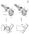
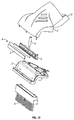
Figure 1 andFigure 10 are an exploded view of a first embodiment of the invention; -
Figure 2 is an exploded view of a first embodiment of the invention; -
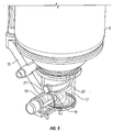
Figure 3 is an exploded view of a second embodiment; -
Figure 4 is an exploded view of a second embodiment; and -
Figure 5 is a cross-sectional view of a second embodiment; -
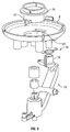
Figure 6 is an exploded view of a third embodiment; -
Figure 7a is a cross-sectional view of a third embodiment; -
Figure 7b is a cross-sectional view of a third embodiment; -
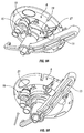
Figure 8 is an exploded view of a fourth embodiment; -
Figure 9a is a view of a fourth embodiment; -
Figure 9b is a view of a fourth embodiment. - With reference to
Figures 1 ,2 and10 it can be seen that the device (1) of the invention comprises a two-part body (2). The body (2) includes a cylindrical container receiver (3) and a nozzle assembly (a). - The nozzle assembly (a) comprises a fluid conduit (4) fluidly connected to the container receiver. The nozzle assembly further comprises a manifold assembly (b) which includes a foam core (c). The manifold assembly (b) is arranged towards the front of the body (2)
- The body (2) has an associated brush section (d) mounted thereon.
- The body has a handle (not shown) which can be accommodated by a handle receiving aperture (5).
- In assembly a container (6) (an inverted aerosol canister) is mounted to the container receiver (3). The container (6) contains a predetermined amount of a treating composition and having a dispensing opening (not shown) in fluid communication with the fluid conduit (4).
- The fluid conduit (4) includes a rotation valve (7). The rotation valve is disposed under a cover plate (8). The rotation valve (7) is operable by a container member (9) attached to and extending from the container (6), adjacent the dispensing opening. The container member is in the form of a pair of horns (10) extending from a cylindrical base (11). The horns (10) have an incision (12) adjacent the base (11).
- The rotation valve (7) is operated by insertion of the container member horns (10) into receiving apertures (13) in the cover plate (8). Further insertion occurs until the horns (10) abut against valve operating members (14).
- Then by rotation of the container (6), rotation of the horns (10) of the container member (9) occurs, which in turn causes rotation of the valve operating members (14). This opens the fluid conduit (4). Over rotation of the container (6) is prevented when the incision (12) of the horns (10) abuts against the cover plate (8).
- In this position the operation of the container (6) may occur to cause dispense of the container (6) contents through the fluid conduit (4). (The full operation mechanism is not shown. However a pivot (15) which comprises a portion of the operating mechanism is shown).
- With reference to
Figures 3 to 5 it can be seen that the device (1) comprises a locking means (16). - The locking means comprises a barrel (17) into which a rod-shaped latch (18) penetrates, when in a locking position. An end of the barrel (17) is intended to receive the canister end of an operating pivot (15). In this way (when the latch (18) penetrates the lock barrel (17)) the lock prevents movement of the aerosol canister end of the pivot (15) up towards the aerosol canister (6).
- The container member (9) comprises a bayonet (19). The end of the latch (18) which is intended to meet the bayonet (19) is angled such that movement of the bayonet (19) against the latch (18) causes a movement of the latch (18) away from the bayonet (19). The movement of the bayonet (19) against the latch (18) is in a circular fashion within the barrel (17) of the locking means (16). To achieve this, the barrel (17) of the locking means (16) has a pilot pathway (20), in the form of an incised channel, which associates with a button (21) arranged on or adjacent the bayonet (19). The pilot pathway (20) is arranged in a helical manner such that as the container member (9) is pushed into the barrel (17) it is rotated further with a greater degree of penetration. The pilot pathway (20) terminates such that at maximum allowed penetration the container member (9) and the latch (18) are fully engaged and the lock mechanism (16) is fully dis-engaged.
- In this position the operation of the container (6) may occur to cause dispense of the container (6) contents through the fluid conduit (4). (The full operation mechanism is not shown. However a pivot (15) which comprises a portion of the operating mechanism is shown).
- With reference to
Figures 6 ,7a and 7b it can be seen that the device (1) comprises a locking means (16). - The locking means comprises a barrel (17) into which a rod-shaped latch (18) penetrates, when in a locking position (bias into this position by a spring). An end of the barrel (17) is intended to receive the canister end of an operating pivot (15). In this way (when the latch (18) penetrates the lock barrel (17)) the lock prevents movement of the aerosol canister end of the pivot (15) up towards the aerosol canister (6). A shoulder of the pivot (15) abuts against the latch (18).
- The container member (9) comprises a bayonet (19). The end of the latch (18) which is intended to meet the bayonet (19) is angled such that movement of the bayonet (19) against the latch (18) causes a movement of the latch (18) away from the bayonet (19). The movement of the bayonet (19) against the latch (18) is in a linear / axial fashion within the barrel (17) of the locking means (16). To achieve this, the barrel (17) of the locking means (16) has a pilot pathway (20), in the form of a shaped / orificed plate, which associates with the bayonet (19), such that the bayonet may only be introduced into the pilot pathway (20) when in a certain orientation. The pilot pathway (20) is arranged such that as the container member (9) is pushed into the barrel (17) at maximum allowed penetration the container member (9) and the latch (18) are fully engaged and the lock mechanism (16) is fully dis-engaged.
- In this position the cylindrical container receiver (3) has a lip (22) which retains the container (6) (e.g. by resiliently holding a rim thereof).
- In this position the operation of the container (6) may occur to cause dispense of the container (6) contents through the fluid conduit (4). (The full operation mechanism is not shown. However a pivot (15) which comprises a portion of the operating mechanism is shown).
- With reference to
Figures 8 ,9a and 9b it can be seen that the device (1) comprises a locking means (16). - The locking means comprises a rod-shaped latch (18). The latch (18) is rotatable mounted (bias into the locking position by a spring). In this way the latch (18) prevents movement of the aerosol canister end of the pivot (15) up towards the aerosol canister (6). A shoulder of the pivot (15) abuts against the latch (18).
- The container member (9) comprises a bayonet (19).
- The locking means (16) has a pilot pathway (20), in the form of a shaped / orificed plate, which associates with a button (21) arranged on or adjacent the bayonet (19), such that the bayonet (19) may only be introduced into the pilot pathway (20) when in a certain orientation. The bayonet (19) may be pushed into the pilot pathway (20) such that the button (21) of the bayonet (19) becomes disposed on the opposite side of the pilot pathway (20) from the canister (6).
- Once in this position the canister (6) may be rotated such that the button (21) of the bayonet (19) abuts against the latch. Continued movement causes disengagement of the latch (18) from engagement with the shoulder of the pivot (15).
- In this position the operation of the container (6) may occur to cause dispense of the container (6) contents through the fluid conduit (4). (The full operation mechanism is not shown. However a pivot (15) which comprises a portion of the operating mechanism is shown).
Claims (10)
- A surface treating implement(1), comprising a body (2) including:-a container receiver(3);a nozzle assembly (a) comprising a fluid conduit(4) fluidly connected to the container receiver(3);a container(6) mounted to the container receiver(3), containing a predetermined amount of a treating composition and having a dispensing opening in fluid communication with the fluid conduit (4) ;wherein the body(2) is associated with a handle which includes at least a portion of an activation means for the implement(1), wherein the fluid conduit(4) includes a valve(7), wherein the valve is operable by a container member (9) attached to and / or extending from the container(6), adjacent the dispensing opening wherein the body(2) of the implement(1) includes a variety of brushing means, characterised in that the container member(9) comprises a bayonet projection(10).
- An implement according to claim 1, in which the container comprises an aerosol canister.
- An implement (1) according to claim 1 or 2, in which the valve(7) comprises a rotation valve.
- An implement(1) according to claim 3, in which a rotatable portion of the rotation valve(7) includes a portion of the fluid conduit.
- An implement (1) according to any one of claims 1 to 4, in which the implement(1) comprising a locking means(16).
- An implement (1) according to any one of claims 1 to 5, in which the implement(1) comprises an operating button(21) which may be depressed by a user when activation is required.
- An implement (1) according to claim 6, in which the operating button(21) is associated with a pivot(15) which (when moved) caused operation of the container(6).
- Use of an implement(1) according to any one of claims 1 to 7, in the treatment of a fabric / textile material or a carpet.
- Use according to claim 8, in which the cleaning operation step for a carpet includes the following steps:-a) application of the composition to a stain,b) allowing the composition to absorb the stain, andc) removing the composition.
- Use according to claim 9 in which the removal step (c) comprises the use of a domestic vacuum cleaner.
Priority Applications (1)
| Application Number | Priority Date | Filing Date | Title |
|---|---|---|---|
| EP14152128.6A EP2724655A1 (en) | 2011-01-21 | 2012-01-11 | Product |
Applications Claiming Priority (2)
| Application Number | Priority Date | Filing Date | Title |
|---|---|---|---|
| GBGB1101006.3A GB201101006D0 (en) | 2011-01-21 | 2011-01-21 | Product |
| PCT/GB2012/050046 WO2012098376A1 (en) | 2011-01-21 | 2012-01-11 | Product |
Related Child Applications (2)
| Application Number | Title | Priority Date | Filing Date |
|---|---|---|---|
| EP14152128.6A Division EP2724655A1 (en) | 2011-01-21 | 2012-01-11 | Product |
| EP14152128.6A Division-Into EP2724655A1 (en) | 2011-01-21 | 2012-01-11 | Product |
Publications (2)
| Publication Number | Publication Date |
|---|---|
| EP2665402A1 EP2665402A1 (en) | 2013-11-27 |
| EP2665402B1 true EP2665402B1 (en) | 2016-11-02 |
Family
ID=43769363
Family Applications (2)
| Application Number | Title | Priority Date | Filing Date |
|---|---|---|---|
| EP14152128.6A Withdrawn EP2724655A1 (en) | 2011-01-21 | 2012-01-11 | Product |
| EP12700520.5A Not-in-force EP2665402B1 (en) | 2011-01-21 | 2012-01-11 | Product |
Family Applications Before (1)
| Application Number | Title | Priority Date | Filing Date |
|---|---|---|---|
| EP14152128.6A Withdrawn EP2724655A1 (en) | 2011-01-21 | 2012-01-11 | Product |
Country Status (10)
| Country | Link |
|---|---|
| US (1) | US9307880B2 (en) |
| EP (2) | EP2724655A1 (en) |
| CN (2) | CN105231961A (en) |
| AU (1) | AU2012208428B2 (en) |
| BR (1) | BR112013018588B1 (en) |
| CA (1) | CA2824718C (en) |
| GB (1) | GB201101006D0 (en) |
| PL (1) | PL2665402T3 (en) |
| WO (1) | WO2012098376A1 (en) |
| ZA (1) | ZA201304686B (en) |
Families Citing this family (8)
| Publication number | Priority date | Publication date | Assignee | Title |
|---|---|---|---|---|
| GB0913488D0 (en) * | 2009-08-01 | 2009-09-16 | Reckitt Benckiser Nv | Product |
| GB201101006D0 (en) | 2011-01-21 | 2011-03-09 | Reckitt Benckiser Nv | Product |
| EP3253684B1 (en) | 2016-02-25 | 2020-02-19 | Turtle Wax, Inc. | Spray cap system |
| USD845001S1 (en) | 2016-02-25 | 2019-04-09 | Turtle Wax, Inc. | Scrub brush |
| US10239185B2 (en) | 2017-08-23 | 2019-03-26 | Aeroetch Holdings, Inc. | Self-powered pressurized granular particle ejector tool with remote operation |
| US10549292B2 (en) * | 2018-02-23 | 2020-02-04 | Icp Adhesives And Sealants, Inc. | Fluid dispensing device |
| US10351334B1 (en) * | 2018-02-23 | 2019-07-16 | Icp Adhesives And Sealants, Inc. | Fluid dispensing device |
| US12434350B2 (en) | 2021-03-08 | 2025-10-07 | Aeroetch Holdings, Inc. | Atmospheric pressure venturi intermix regulator cartridge and emission conduit |
Family Cites Families (83)
| Publication number | Priority date | Publication date | Assignee | Title |
|---|---|---|---|---|
| US2649331A (en) | 1950-08-09 | 1953-08-18 | Bridgeport Brass Co | Device for intermittently discharging fluid under pressure |
| NL267775A (en) | 1959-08-05 | |||
| US5110011A (en) | 1990-06-29 | 1992-05-05 | Minnesota Mining And Manufacturing Company | Non-releasable spray head and dip tube assembly |
| US3303970A (en) | 1964-07-14 | 1967-02-14 | Jerome Marrow | Device for simultaneously dispensing from plural sources |
| US3575319A (en) | 1968-07-11 | 1971-04-20 | Upjohn Co | Portable dispenser for polymer foams |
| US3592364A (en) * | 1969-08-27 | 1971-07-13 | Geigy Chem Corp | Retaining ring incorporating a cutting edge for use in an aerosol dispenser valve assembly |
| US3659791A (en) | 1969-11-17 | 1972-05-02 | William O Clark | Spray gun adaptor for aerosal cans |
| DE2153445A1 (en) | 1970-11-02 | 1972-05-10 | Precision Valve Corp., Yonkers, N.Y. (V.St.A.) | Actuator for controlling the delivery of material from a pressure vessel |
| US3738536A (en) | 1971-06-28 | 1973-06-12 | Sunbeam Plastics Corp | Child proof protective overcap for an aerosol can |
| US3848778A (en) | 1972-08-14 | 1974-11-19 | P Meshberg | Childproof actuator assembly |
| US3765573A (en) | 1972-11-01 | 1973-10-16 | I Landsman | Actuating cap for an aerosol device |
| US4171758A (en) | 1977-04-11 | 1979-10-23 | S. C. Johnson & Son, Inc. | Child-safe actuator for pressurized container |
| FR2482242B1 (en) | 1980-05-06 | 1986-02-07 | Normos Norbert | SAFETY VALVE, ESPECIALLY FOR CONTAINERS CONTAINING A PRESSURIZED FLUID |
| EP0062609A1 (en) * | 1981-03-27 | 1982-10-13 | Plastics Consultency Office AG | Multi-component dispensing container with a valve |
| GB2112462B (en) * | 1981-12-03 | 1985-06-19 | Oreal | A dispenser cap for a pressurised container and a corresponding unit |
| JPS63267463A (en) * | 1986-12-19 | 1988-11-04 | Araki Rubber:Kk | Aerial spray - working aids |
| US4815637A (en) * | 1988-04-21 | 1989-03-28 | Nellis Russell L | Cap assembly for use with canned aerosol lubricant |
| DE3879951T2 (en) | 1988-12-22 | 1993-09-16 | Artebel Sa | OPERATING DEVICE FOR APPLYING A LIQUID. |
| US5180109A (en) | 1991-06-05 | 1993-01-19 | Minnesota Mining And Manufacturing Company | Single use spray dispensing assembly |
| DE9110171U1 (en) | 1991-08-16 | 1993-03-25 | Vorwerk & Co Interholding Gmbh, 5600 Wuppertal | Steam cleaning device |
| US5514026A (en) | 1993-10-20 | 1996-05-07 | Sandair Nevada, Inc. | Unitary, hand-held, portable, self-powered refillable mixed-media ejector tool |
| US5368202A (en) * | 1993-11-19 | 1994-11-29 | Smrt; Thomas J. | Handle for holding and remotely actuating an aerosol container |
| US5500977A (en) * | 1994-01-14 | 1996-03-26 | The Hoover Company | Upright carpet extractor |
| US5534167A (en) | 1994-06-13 | 1996-07-09 | S. C. Johnson & Son, Inc. | Carpet cleaning and restoring composition |
| WO1997049324A2 (en) | 1996-06-26 | 1997-12-31 | Matsushita Home Appliance Corporation Of America | Extractor with twin, counterrotating agitators |
| US5769279A (en) | 1996-07-19 | 1998-06-23 | Smrt; Thomas J. | Aerosol container discharging apparatus with flag staking capability |
| US5826795A (en) | 1996-08-19 | 1998-10-27 | Minnesota Mining And Manufacturing Company | Spray assembly |
| US6082588A (en) * | 1997-01-10 | 2000-07-04 | Lever Brothers Company, Division Of Conopco, Inc. | Dual compartment package and pumps |
| US7204041B1 (en) | 1997-08-14 | 2007-04-17 | Promdx Technology, Inc. | Ergonomic systems and methods providing intelligent adaptive surfaces |
| JP3865485B2 (en) | 1997-11-07 | 2007-01-10 | 東洋エアゾール工業株式会社 | Flow control device for aerosol containers |
| US5924599A (en) | 1998-01-16 | 1999-07-20 | Flexible Products Company | Dispensing system with unique container attachment |
| US6056213A (en) | 1998-01-30 | 2000-05-02 | 3M Innovative Properties Company | Modular system for atomizing a liquid |
| US6053373A (en) * | 1998-10-16 | 2000-04-25 | S.C. Johnson Commercial Markets, Inc. | Fluid dispensing device |
| US6669391B2 (en) | 1998-11-09 | 2003-12-30 | The Procter & Gamble Company | Cleaning composition, pad, wipe, implement, and system and method of use thereof |
| US6579023B2 (en) * | 1998-12-01 | 2003-06-17 | The Procter & Gamble Company | Cleaning implements |
| US7048458B2 (en) | 2000-03-24 | 2006-05-23 | The Clorox Company | Fluid valve and actuator for inverted fluid reservoir |
| US6976802B2 (en) * | 2000-10-11 | 2005-12-20 | The Clorox Company | Fluid distribution nozzle and stream pattern |
| DK2292288T3 (en) * | 2000-07-24 | 2018-01-02 | Clinical Designs Ltd | Dispenser |
| JP4832661B2 (en) | 2000-10-17 | 2011-12-07 | 株式会社ダイゾー | Rotating aerosol products |
| EP1229107A1 (en) | 2001-02-05 | 2002-08-07 | The Procter & Gamble Company | Process of cleaning carpets with a composition comprising a fluorinated compound |
| US6663307B2 (en) * | 2001-09-14 | 2003-12-16 | S. C. Johnson & Son, Inc. | Apparatus for spraying a remote target or area |
| US6551001B2 (en) * | 2001-09-14 | 2003-04-22 | S. C. Johnson & Son, Inc. | Cleaning device with a trigger-actuated spray canister |
| US6866165B2 (en) * | 2001-09-14 | 2005-03-15 | S.C. Johnson & Son, Inc. | Spray canister |
| US6497525B1 (en) * | 2002-04-05 | 2002-12-24 | Chiu-Yun Huang | Mop with a liquid spraying device |
| US7232262B2 (en) | 2002-07-18 | 2007-06-19 | Westover Scientific, Inc. | Fiber-optic endface cleaning apparatus and method |
| US7906473B2 (en) | 2002-09-13 | 2011-03-15 | Bissell Homecare, Inc. | Manual spray cleaner |
| US6953299B2 (en) * | 2003-01-16 | 2005-10-11 | The Clorox Company | Cleaning implement with interchangeable tool heads |
| US7007338B2 (en) * | 2003-01-16 | 2006-03-07 | Garabedian Jr Aram | Advanced aerosol cleaning system |
| US20040141797A1 (en) * | 2003-01-16 | 2004-07-22 | Aram Garabedian | Advanced aerosol cleaning system |
| US6868989B2 (en) | 2003-03-10 | 2005-03-22 | S.C. Johnson & Son, Inc. | Cleaner with adjustable aerosol canister retainer |
| US6889917B2 (en) * | 2003-03-10 | 2005-05-10 | S.C. Johnson & Son, Inc. | Cleaning device with universal motion quick disconnect head |
| US8267607B2 (en) * | 2003-06-26 | 2012-09-18 | Harris Research, Inc. | Surface working apparatus |
| US20050112022A1 (en) | 2003-11-26 | 2005-05-26 | Morgan David M. | Room sanitizing method and apparatus |
| US8061562B2 (en) | 2004-10-12 | 2011-11-22 | S.C. Johnson & Son, Inc. | Compact spray device |
| DE202004019888U1 (en) | 2004-12-20 | 2005-02-24 | Avet Ag | Cleaning device with cleaning liquid supply container, e.g. mop, has protruding part of container inserted into cavity in end of container holder |
| US20060201970A1 (en) | 2005-03-11 | 2006-09-14 | Jasek Sidney J | Safety nozzle for aerosol can |
| JP4734124B2 (en) * | 2005-04-05 | 2011-07-27 | ユニ・チャーム株式会社 | Cleaning tool |
| US20090249533A1 (en) | 2005-12-20 | 2009-10-08 | Sawalski Michael M | Toilet Bowl Cleaning and/or Deodorizing Device |
| US7922041B2 (en) * | 2005-12-29 | 2011-04-12 | The Procter & Gamble Company | Spray dispensers |
| DE102006009768B3 (en) | 2006-03-01 | 2007-09-06 | Avet Ag | Applicator for liquid coating agents |
| US7631783B1 (en) | 2006-06-12 | 2009-12-15 | Rodney Laible | Docking station for a liquid container |
| GB0620676D0 (en) * | 2006-10-18 | 2006-11-29 | Reckitt Benckiser Uk Ltd | A cleaning device |
| DE112008000125T5 (en) | 2007-01-22 | 2009-11-26 | The Procter & Gamble Company, Cincinnati | A method of carpet cleaning comprising melamine foam |
| US9186028B2 (en) | 2007-03-05 | 2015-11-17 | Bissell Homecare, Inc. | Accessory tool for a vacuum cleaner |
| US7337989B1 (en) * | 2007-03-26 | 2008-03-04 | S.C. Johnson & Son, Inc. | Automated sprayer with manually-adjustable nozzle |
| EP2182831B9 (en) * | 2007-08-07 | 2014-04-16 | Bissell Homecare, Inc. | Surface treating implement |
| GB0725198D0 (en) * | 2007-12-24 | 2008-01-30 | Reckitt Benckiser Uk Ltd | Cleaning device |
| USD613918S1 (en) * | 2008-01-11 | 2010-04-13 | Bissell Homecare, Inc. | Cleaning fluid dispenser |
| US8016167B2 (en) * | 2008-09-09 | 2011-09-13 | The Clorox Company | Aerosol sprayer |
| KR100892628B1 (en) * | 2008-09-30 | 2009-04-08 | 주식회사 효신 | Wet cleaner |
| US9061817B2 (en) | 2008-11-12 | 2015-06-23 | Meadwestvaco Calmar, Inc. | Spray devices and methods for using the same |
| US8475070B1 (en) * | 2009-02-11 | 2013-07-02 | Bissell Homecare, Inc. | Hard surface cleaning tool |
| CN201445486U (en) * | 2009-03-04 | 2010-05-05 | 武凤娇 | Steam mop |
| GB2469476B (en) * | 2009-04-15 | 2013-05-15 | Akzo Nobel Coatings Int Bv | A decking coating composition applicator |
| EP2445558B1 (en) | 2009-06-25 | 2016-06-29 | Boehringer Ingelheim Vetmedica GmbH | Inhaler |
| US8276832B2 (en) | 2009-07-22 | 2012-10-02 | S.C. Johnson & Son, Inc. | Multiple spray actuator overcap |
| GB0913488D0 (en) * | 2009-08-01 | 2009-09-16 | Reckitt Benckiser Nv | Product |
| AU2010249272C1 (en) | 2009-12-18 | 2014-07-17 | Bissell Inc. | Dry vacuum cleaner with spot cleaning |
| US20120217243A1 (en) * | 2010-05-21 | 2012-08-30 | Erica Eden Cohen | Shroud and Dispensing System for a Handheld Container |
| IT1400715B1 (en) | 2010-07-06 | 2013-06-28 | Capsol S P A | DOUBLE CAP OF OPERATION AND DELIVERY COUPLED WITH AN AEROSOL BOTTLE. |
| GB201101006D0 (en) | 2011-01-21 | 2011-03-09 | Reckitt Benckiser Nv | Product |
| US20120192894A1 (en) * | 2011-01-27 | 2012-08-02 | 3M Innovative Properties Company | Cleaning and sealing solution applicator tool for surfaces such as stone, porous tile, or grout |
| USD686383S1 (en) * | 2011-04-19 | 2013-07-16 | Reckitt Benckiser N. V. | Sweeper |
-
2011
- 2011-01-21 GB GBGB1101006.3A patent/GB201101006D0/en not_active Ceased
-
2012
- 2012-01-11 PL PL12700520T patent/PL2665402T3/en unknown
- 2012-01-11 EP EP14152128.6A patent/EP2724655A1/en not_active Withdrawn
- 2012-01-11 WO PCT/GB2012/050046 patent/WO2012098376A1/en not_active Ceased
- 2012-01-11 CN CN201510561475.2A patent/CN105231961A/en active Pending
- 2012-01-11 CN CN201280005836.XA patent/CN103501674B/en not_active Expired - Fee Related
- 2012-01-11 EP EP12700520.5A patent/EP2665402B1/en not_active Not-in-force
- 2012-01-11 US US13/996,809 patent/US9307880B2/en active Active
- 2012-01-11 AU AU2012208428A patent/AU2012208428B2/en not_active Ceased
- 2012-01-11 CA CA2824718A patent/CA2824718C/en not_active Expired - Fee Related
- 2012-01-11 BR BR112013018588-0A patent/BR112013018588B1/en not_active IP Right Cessation
-
2013
- 2013-06-24 ZA ZA2013/04686A patent/ZA201304686B/en unknown
Also Published As
| Publication number | Publication date |
|---|---|
| CN105231961A (en) | 2016-01-13 |
| CA2824718C (en) | 2018-09-11 |
| WO2012098376A1 (en) | 2012-07-26 |
| EP2724655A1 (en) | 2014-04-30 |
| AU2012208428A1 (en) | 2013-07-11 |
| EP2665402A1 (en) | 2013-11-27 |
| GB201101006D0 (en) | 2011-03-09 |
| CA2824718A1 (en) | 2012-07-26 |
| CN103501674B (en) | 2016-05-18 |
| CN103501674A (en) | 2014-01-08 |
| AU2012208428B2 (en) | 2016-05-12 |
| US9307880B2 (en) | 2016-04-12 |
| BR112013018588A2 (en) | 2016-09-27 |
| BR112013018588B1 (en) | 2020-09-24 |
| ZA201304686B (en) | 2014-09-25 |
| RU2013138741A (en) | 2015-02-27 |
| US20130283543A1 (en) | 2013-10-31 |
| PL2665402T3 (en) | 2017-09-29 |
Similar Documents
| Publication | Publication Date | Title |
|---|---|---|
| EP2534993B1 (en) | A fluid dispensing surface treating implement | |
| US9307880B2 (en) | Surface treating implement having locking means and brush elements | |
| CN101801253B (en) | Surface treating implement | |
| US11950747B2 (en) | Extraction cleaner and cleanout tool for the same | |
| WO2006109388A1 (en) | Cleaning tool | |
| WO2010022116A2 (en) | Plural nozzle cleaning implement | |
| CN102085082A (en) | Low moisture extraction deep cleaning | |
| WO2006109387A1 (en) | Cleaning tool | |
| GB2531872A (en) | Upward spraying floor cleaning apparatus | |
| RU2575432C2 (en) | Device for surface treatment (versions) and its use |
Legal Events
| Date | Code | Title | Description |
|---|---|---|---|
| PUAI | Public reference made under article 153(3) epc to a published international application that has entered the european phase |
Free format text: ORIGINAL CODE: 0009012 |
|
| 17P | Request for examination filed |
Effective date: 20130619 |
|
| AK | Designated contracting states |
Kind code of ref document: A1 Designated state(s): AL AT BE BG CH CY CZ DE DK EE ES FI FR GB GR HR HU IE IS IT LI LT LU LV MC MK MT NL NO PL PT RO RS SE SI SK SM TR |
|
| DAX | Request for extension of the european patent (deleted) | ||
| RAP1 | Party data changed (applicant data changed or rights of an application transferred) |
Owner name: RECKITT BENCKISER FINISH B.V. |
|
| RAP1 | Party data changed (applicant data changed or rights of an application transferred) |
Owner name: RECKITT BENCKISER VANISH B.V. |
|
| GRAP | Despatch of communication of intention to grant a patent |
Free format text: ORIGINAL CODE: EPIDOSNIGR1 |
|
| INTG | Intention to grant announced |
Effective date: 20160610 |
|
| GRAS | Grant fee paid |
Free format text: ORIGINAL CODE: EPIDOSNIGR3 |
|
| GRAA | (expected) grant |
Free format text: ORIGINAL CODE: 0009210 |
|
| AK | Designated contracting states |
Kind code of ref document: B1 Designated state(s): AL AT BE BG CH CY CZ DE DK EE ES FI FR GB GR HR HU IE IS IT LI LT LU LV MC MK MT NL NO PL PT RO RS SE SI SK SM TR |
|
| REG | Reference to a national code |
Ref country code: GB Ref legal event code: FG4D |
|
| REG | Reference to a national code |
Ref country code: AT Ref legal event code: REF Ref document number: 840943 Country of ref document: AT Kind code of ref document: T Effective date: 20161115 Ref country code: CH Ref legal event code: EP |
|
| REG | Reference to a national code |
Ref country code: IE Ref legal event code: FG4D |
|
| REG | Reference to a national code |
Ref country code: DE Ref legal event code: R096 Ref document number: 602012024796 Country of ref document: DE |
|
| REG | Reference to a national code |
Ref country code: FR Ref legal event code: PLFP Year of fee payment: 6 |
|
| PG25 | Lapsed in a contracting state [announced via postgrant information from national office to epo] |
Ref country code: LV Free format text: LAPSE BECAUSE OF FAILURE TO SUBMIT A TRANSLATION OF THE DESCRIPTION OR TO PAY THE FEE WITHIN THE PRESCRIBED TIME-LIMIT Effective date: 20161102 |
|
| REG | Reference to a national code |
Ref country code: NL Ref legal event code: MP Effective date: 20161102 |
|
| REG | Reference to a national code |
Ref country code: LT Ref legal event code: MG4D |
|
| REG | Reference to a national code |
Ref country code: AT Ref legal event code: MK05 Ref document number: 840943 Country of ref document: AT Kind code of ref document: T Effective date: 20161102 |
|
| PG25 | Lapsed in a contracting state [announced via postgrant information from national office to epo] |
Ref country code: NL Free format text: LAPSE BECAUSE OF FAILURE TO SUBMIT A TRANSLATION OF THE DESCRIPTION OR TO PAY THE FEE WITHIN THE PRESCRIBED TIME-LIMIT Effective date: 20161102 Ref country code: NO Free format text: LAPSE BECAUSE OF FAILURE TO SUBMIT A TRANSLATION OF THE DESCRIPTION OR TO PAY THE FEE WITHIN THE PRESCRIBED TIME-LIMIT Effective date: 20170202 Ref country code: LT Free format text: LAPSE BECAUSE OF FAILURE TO SUBMIT A TRANSLATION OF THE DESCRIPTION OR TO PAY THE FEE WITHIN THE PRESCRIBED TIME-LIMIT Effective date: 20161102 Ref country code: SE Free format text: LAPSE BECAUSE OF FAILURE TO SUBMIT A TRANSLATION OF THE DESCRIPTION OR TO PAY THE FEE WITHIN THE PRESCRIBED TIME-LIMIT Effective date: 20161102 Ref country code: GR Free format text: LAPSE BECAUSE OF FAILURE TO SUBMIT A TRANSLATION OF THE DESCRIPTION OR TO PAY THE FEE WITHIN THE PRESCRIBED TIME-LIMIT Effective date: 20170203 |
|
| PG25 | Lapsed in a contracting state [announced via postgrant information from national office to epo] |
Ref country code: HR Free format text: LAPSE BECAUSE OF FAILURE TO SUBMIT A TRANSLATION OF THE DESCRIPTION OR TO PAY THE FEE WITHIN THE PRESCRIBED TIME-LIMIT Effective date: 20161102 Ref country code: BE Free format text: LAPSE BECAUSE OF NON-PAYMENT OF DUE FEES Effective date: 20170131 Ref country code: AT Free format text: LAPSE BECAUSE OF FAILURE TO SUBMIT A TRANSLATION OF THE DESCRIPTION OR TO PAY THE FEE WITHIN THE PRESCRIBED TIME-LIMIT Effective date: 20161102 Ref country code: PT Free format text: LAPSE BECAUSE OF FAILURE TO SUBMIT A TRANSLATION OF THE DESCRIPTION OR TO PAY THE FEE WITHIN THE PRESCRIBED TIME-LIMIT Effective date: 20170302 Ref country code: ES Free format text: LAPSE BECAUSE OF FAILURE TO SUBMIT A TRANSLATION OF THE DESCRIPTION OR TO PAY THE FEE WITHIN THE PRESCRIBED TIME-LIMIT Effective date: 20161102 Ref country code: RS Free format text: LAPSE BECAUSE OF FAILURE TO SUBMIT A TRANSLATION OF THE DESCRIPTION OR TO PAY THE FEE WITHIN THE PRESCRIBED TIME-LIMIT Effective date: 20161102 Ref country code: IS Free format text: LAPSE BECAUSE OF FAILURE TO SUBMIT A TRANSLATION OF THE DESCRIPTION OR TO PAY THE FEE WITHIN THE PRESCRIBED TIME-LIMIT Effective date: 20170302 Ref country code: FI Free format text: LAPSE BECAUSE OF FAILURE TO SUBMIT A TRANSLATION OF THE DESCRIPTION OR TO PAY THE FEE WITHIN THE PRESCRIBED TIME-LIMIT Effective date: 20161102 |
|
| PG25 | Lapsed in a contracting state [announced via postgrant information from national office to epo] |
Ref country code: SK Free format text: LAPSE BECAUSE OF FAILURE TO SUBMIT A TRANSLATION OF THE DESCRIPTION OR TO PAY THE FEE WITHIN THE PRESCRIBED TIME-LIMIT Effective date: 20161102 Ref country code: DK Free format text: LAPSE BECAUSE OF FAILURE TO SUBMIT A TRANSLATION OF THE DESCRIPTION OR TO PAY THE FEE WITHIN THE PRESCRIBED TIME-LIMIT Effective date: 20161102 Ref country code: RO Free format text: LAPSE BECAUSE OF FAILURE TO SUBMIT A TRANSLATION OF THE DESCRIPTION OR TO PAY THE FEE WITHIN THE PRESCRIBED TIME-LIMIT Effective date: 20161102 Ref country code: EE Free format text: LAPSE BECAUSE OF FAILURE TO SUBMIT A TRANSLATION OF THE DESCRIPTION OR TO PAY THE FEE WITHIN THE PRESCRIBED TIME-LIMIT Effective date: 20161102 Ref country code: CZ Free format text: LAPSE BECAUSE OF FAILURE TO SUBMIT A TRANSLATION OF THE DESCRIPTION OR TO PAY THE FEE WITHIN THE PRESCRIBED TIME-LIMIT Effective date: 20161102 |
|
| REG | Reference to a national code |
Ref country code: DE Ref legal event code: R097 Ref document number: 602012024796 Country of ref document: DE |
|
| PG25 | Lapsed in a contracting state [announced via postgrant information from national office to epo] |
Ref country code: SM Free format text: LAPSE BECAUSE OF FAILURE TO SUBMIT A TRANSLATION OF THE DESCRIPTION OR TO PAY THE FEE WITHIN THE PRESCRIBED TIME-LIMIT Effective date: 20161102 Ref country code: BG Free format text: LAPSE BECAUSE OF FAILURE TO SUBMIT A TRANSLATION OF THE DESCRIPTION OR TO PAY THE FEE WITHIN THE PRESCRIBED TIME-LIMIT Effective date: 20170202 Ref country code: BE Free format text: LAPSE BECAUSE OF FAILURE TO SUBMIT A TRANSLATION OF THE DESCRIPTION OR TO PAY THE FEE WITHIN THE PRESCRIBED TIME-LIMIT Effective date: 20161102 |
|
| REG | Reference to a national code |
Ref country code: CH Ref legal event code: PL |
|
| PLBE | No opposition filed within time limit |
Free format text: ORIGINAL CODE: 0009261 |
|
| STAA | Information on the status of an ep patent application or granted ep patent |
Free format text: STATUS: NO OPPOSITION FILED WITHIN TIME LIMIT |
|
| PG25 | Lapsed in a contracting state [announced via postgrant information from national office to epo] |
Ref country code: MC Free format text: LAPSE BECAUSE OF FAILURE TO SUBMIT A TRANSLATION OF THE DESCRIPTION OR TO PAY THE FEE WITHIN THE PRESCRIBED TIME-LIMIT Effective date: 20161102 |
|
| 26N | No opposition filed |
Effective date: 20170803 |
|
| PG25 | Lapsed in a contracting state [announced via postgrant information from national office to epo] |
Ref country code: CH Free format text: LAPSE BECAUSE OF NON-PAYMENT OF DUE FEES Effective date: 20170131 Ref country code: LI Free format text: LAPSE BECAUSE OF NON-PAYMENT OF DUE FEES Effective date: 20170131 |
|
| REG | Reference to a national code |
Ref country code: IE Ref legal event code: MM4A |
|
| PG25 | Lapsed in a contracting state [announced via postgrant information from national office to epo] |
Ref country code: LU Free format text: LAPSE BECAUSE OF NON-PAYMENT OF DUE FEES Effective date: 20170111 Ref country code: SI Free format text: LAPSE BECAUSE OF FAILURE TO SUBMIT A TRANSLATION OF THE DESCRIPTION OR TO PAY THE FEE WITHIN THE PRESCRIBED TIME-LIMIT Effective date: 20161102 |
|
| REG | Reference to a national code |
Ref country code: FR Ref legal event code: PLFP Year of fee payment: 7 |
|
| PG25 | Lapsed in a contracting state [announced via postgrant information from national office to epo] |
Ref country code: IE Free format text: LAPSE BECAUSE OF NON-PAYMENT OF DUE FEES Effective date: 20170111 |
|
| PG25 | Lapsed in a contracting state [announced via postgrant information from national office to epo] |
Ref country code: MT Free format text: LAPSE BECAUSE OF NON-PAYMENT OF DUE FEES Effective date: 20170111 |
|
| PGFP | Annual fee paid to national office [announced via postgrant information from national office to epo] |
Ref country code: PL Payment date: 20181228 Year of fee payment: 8 |
|
| PGFP | Annual fee paid to national office [announced via postgrant information from national office to epo] |
Ref country code: ES Payment date: 20190201 Year of fee payment: 8 |
|
| PGFP | Annual fee paid to national office [announced via postgrant information from national office to epo] |
Ref country code: TR Payment date: 20190128 Year of fee payment: 8 |
|
| PG25 | Lapsed in a contracting state [announced via postgrant information from national office to epo] |
Ref country code: HU Free format text: LAPSE BECAUSE OF FAILURE TO SUBMIT A TRANSLATION OF THE DESCRIPTION OR TO PAY THE FEE WITHIN THE PRESCRIBED TIME-LIMIT; INVALID AB INITIO Effective date: 20120111 |
|
| PG25 | Lapsed in a contracting state [announced via postgrant information from national office to epo] |
Ref country code: CY Free format text: LAPSE BECAUSE OF NON-PAYMENT OF DUE FEES Effective date: 20161102 |
|
| PG25 | Lapsed in a contracting state [announced via postgrant information from national office to epo] |
Ref country code: MK Free format text: LAPSE BECAUSE OF FAILURE TO SUBMIT A TRANSLATION OF THE DESCRIPTION OR TO PAY THE FEE WITHIN THE PRESCRIBED TIME-LIMIT Effective date: 20161102 |
|
| PG25 | Lapsed in a contracting state [announced via postgrant information from national office to epo] |
Ref country code: AL Free format text: LAPSE BECAUSE OF FAILURE TO SUBMIT A TRANSLATION OF THE DESCRIPTION OR TO PAY THE FEE WITHIN THE PRESCRIBED TIME-LIMIT Effective date: 20161102 |
|
| PG25 | Lapsed in a contracting state [announced via postgrant information from national office to epo] |
Ref country code: IT Free format text: LAPSE BECAUSE OF NON-PAYMENT OF DUE FEES Effective date: 20200111 |
|
| PG25 | Lapsed in a contracting state [announced via postgrant information from national office to epo] |
Ref country code: PL Free format text: LAPSE BECAUSE OF NON-PAYMENT OF DUE FEES Effective date: 20200111 |
|
| PG25 | Lapsed in a contracting state [announced via postgrant information from national office to epo] |
Ref country code: TR Free format text: LAPSE BECAUSE OF NON-PAYMENT OF DUE FEES Effective date: 20200111 |
|
| P01 | Opt-out of the competence of the unified patent court (upc) registered |
Effective date: 20230513 |
|
| PGFP | Annual fee paid to national office [announced via postgrant information from national office to epo] |
Ref country code: GB Payment date: 20231130 Year of fee payment: 13 |
|
| PGFP | Annual fee paid to national office [announced via postgrant information from national office to epo] |
Ref country code: FR Payment date: 20231212 Year of fee payment: 13 |
|
| PGFP | Annual fee paid to national office [announced via postgrant information from national office to epo] |
Ref country code: DE Payment date: 20231205 Year of fee payment: 13 |
|
| REG | Reference to a national code |
Ref country code: DE Ref legal event code: R119 Ref document number: 602012024796 Country of ref document: DE |
|
| GBPC | Gb: european patent ceased through non-payment of renewal fee |
Effective date: 20250111 |
|
| PG25 | Lapsed in a contracting state [announced via postgrant information from national office to epo] |
Ref country code: DE Free format text: LAPSE BECAUSE OF NON-PAYMENT OF DUE FEES Effective date: 20250801 |
|
| PG25 | Lapsed in a contracting state [announced via postgrant information from national office to epo] |
Ref country code: GB Free format text: LAPSE BECAUSE OF NON-PAYMENT OF DUE FEES Effective date: 20250111 |
|
| PG25 | Lapsed in a contracting state [announced via postgrant information from national office to epo] |
Ref country code: FR Free format text: LAPSE BECAUSE OF NON-PAYMENT OF DUE FEES Effective date: 20250131 |