JP4734124B2 - Cleaning tool - Google Patents
Cleaning tool Download PDFInfo
- Publication number
- JP4734124B2 JP4734124B2 JP2006007997A JP2006007997A JP4734124B2 JP 4734124 B2 JP4734124 B2 JP 4734124B2 JP 2006007997 A JP2006007997 A JP 2006007997A JP 2006007997 A JP2006007997 A JP 2006007997A JP 4734124 B2 JP4734124 B2 JP 4734124B2
- Authority
- JP
- Japan
- Prior art keywords
- container
- valve
- fluid
- injection nozzle
- adapter
- Prior art date
- Legal status (The legal status is an assumption and is not a legal conclusion. Google has not performed a legal analysis and makes no representation as to the accuracy of the status listed.)
- Expired - Fee Related
Links
Images


Classifications
-
- A—HUMAN NECESSITIES
- A47—FURNITURE; DOMESTIC ARTICLES OR APPLIANCES; COFFEE MILLS; SPICE MILLS; SUCTION CLEANERS IN GENERAL
- A47L—DOMESTIC WASHING OR CLEANING; SUCTION CLEANERS IN GENERAL
- A47L13/00—Implements for cleaning floors, carpets, furniture, walls, or wall coverings
- A47L13/10—Scrubbing; Scouring; Cleaning; Polishing
- A47L13/20—Mops
- A47L13/22—Mops with liquid-feeding devices
-
- A—HUMAN NECESSITIES
- A47—FURNITURE; DOMESTIC ARTICLES OR APPLIANCES; COFFEE MILLS; SPICE MILLS; SUCTION CLEANERS IN GENERAL
- A47L—DOMESTIC WASHING OR CLEANING; SUCTION CLEANERS IN GENERAL
- A47L13/00—Implements for cleaning floors, carpets, furniture, walls, or wall coverings
- A47L13/10—Scrubbing; Scouring; Cleaning; Polishing
- A47L13/28—Polishing implements
- A47L13/30—Implements for polishing and waxing or oiling, with dispensers for wax or oil
- A47L13/31—Implements for polishing and waxing or oiling, with dispensers for wax or oil having movable or detachable polishing or shining cloths
- A47L13/312—Implements for polishing and waxing or oiling, with dispensers for wax or oil having movable or detachable polishing or shining cloths supplied with liquid wax or oil
Description
本発明は、清掃具に関する。特に、本発明は、例えば、床、又はカーペットなどを覆うものの清掃具であって、液体供給装置を有する清掃具に関する。 The present invention relates to a cleaning tool. In particular, the present invention relates to a cleaning tool that covers a floor or a carpet, for example, and has a liquid supply device.
例えば、液体供給装置を有する清掃具は、柄の先端に清掃ヘッドを設け、柄のグリップ側に手元操作部を設けている。そして、柄の先端側に押圧ポンプ式吐出容器及びポンプ押圧具を設け、手元操作部をポンプ押圧具に連結する連結部材を柄に沿って設けている。手元操作部に加える手操作により連結部材とポンプ押圧具を介して押圧ポンプ式吐出容器を押圧し、吐出容器から清掃ヘッドの側に液剤を吐出させる清掃具が発明されている(例えば、特許文献1参照)。 For example, a cleaning tool having a liquid supply device is provided with a cleaning head at the tip of a handle and a hand operation unit on the grip side of the handle. And the press pump type discharge container and the pump pressing tool are provided on the front end side of the handle, and a connecting member for connecting the hand operating portion to the pump pressing tool is provided along the handle. There has been invented a cleaning tool that presses a pressure pump type discharge container through a connecting member and a pump pressing tool by a manual operation applied to the hand operation unit, and discharges the liquid agent from the discharge container to the cleaning head side (for example, Patent Documents). 1).
特許文献1によれば、湿式拭きできる清掃具において、静粛に作動し、液剤を安定的に吐出可能にし、かつ軽量化することができる、としている。
特許文献1によれば、ポンプのスプレーノズルから清掃ヘッドの前方及び周辺に液剤を噴霧できるとしている。しかし、つや出し剤やワックス剤を床面に塗工及び払拭する場合には、前方に清掃作業を進めると、塗工した床面を作業者が踏むことになり、例えば、塗工した床面に足型などを残してしまうという問題がある。 According to Patent Document 1, it is possible to spray the liquid agent in front of and around the cleaning head from the spray nozzle of the pump. However, when applying and wiping a polish or wax agent on the floor surface, if the cleaning operation is advanced forward, the operator will step on the coated floor surface, for example, on the coated floor surface. There is a problem of leaving the foot shape.
清掃ヘッドの前方及び周辺に液剤を噴霧する構造の清掃具は、ときに、液剤を室内の家具や電器製品に噴霧する可能性があるという問題が考えられる。作業者の選択により、液剤を清掃ヘッドの前方又は後方に噴霧可能な清掃具が考えられてもよい。そして、これらが本発明の課題といってよい。 A cleaning tool configured to spray a liquid agent in front of and around the cleaning head sometimes has a problem that the liquid agent may be sprayed on indoor furniture or electrical appliances. Depending on the operator's choice, a cleaning tool capable of spraying the liquid agent forward or backward of the cleaning head may be considered. And these may be the subject of the present invention.
本発明は、上述した課題を解決すべく、清掃ヘッドと、この清掃ヘッドに接続され、第1流体を収容する第1容器、又は、第2流体を収容する第2容器を保持可能なバルブ開閉装置と、を備える清掃具であって、使用者の選択により、流体を清掃ヘッドの前方又は後方に噴霧可能な清掃具を提供することを目的とする。 In order to solve the above-described problems, the present invention provides a cleaning head and a valve opening / closing that is connected to the cleaning head and can hold a first container that contains a first fluid or a second container that contains a second fluid. It is an object of the present invention to provide a cleaning tool that can spray a fluid forward or backward of a cleaning head according to a user's selection.
発明者は、上記目的を満たすため、バルブ開閉装置は、第1容器が着脱自在な接続機構と、この接続機構に連結されて第2容器が着脱自在なアダプタと、を備え、第1流通経路は、第1流体を接続機構から清掃ヘッドの外へ噴射する第1噴射ノズルに至り、第2流通経路は、第2流体をアダプタから噴射する第2噴射ノズルに至る構造とし、以下のような新たな清掃具を発明した。 In order to satisfy the above object, the inventor includes a connection mechanism in which the first container is detachable, and an adapter connected to the connection mechanism and in which the second container is detachable. The first fluid is ejected from the connecting mechanism to the outside of the cleaning head, and the second flow path is structured to reach the second fluid nozzle from the adapter to eject the second fluid. Invented a new cleaning tool.
(1) 清掃ヘッドと、把持部と、を備える清掃具であって、前記清掃ヘッドを前方に位置し、前記把持部を後方に位置して使用するときに、前記清掃ヘッドの後方に流体を噴射可能である清掃具。 (1) A cleaning tool including a cleaning head and a gripping portion, wherein when the cleaning head is positioned forward and the gripping portion is positioned rearward, a fluid is passed to the rear of the cleaning head. Cleaning tool that can be jetted.
例えば、清掃ヘッドは底部に清掃作業面を有してよく、把持部は、清掃ヘッドの対向側に設けられる。例えば、清掃ヘッドと把持部はパイプで連結される。そして、(1)の発明は、清掃ヘッドを前方に位置し、把持部を後方に位置して使用するときに、清掃ヘッドの後方に流体を噴射可能である。前記流体は、例えば、後述する第2流体であってよく、例えば、(1)の発明による清掃具は、つや出し剤やワックス剤などの第2流体を床面に噴射でき、使用者は後方に向かって、前記第2流体を床面に塗工していくことができる。そして、塗工した床面を使用者が踏むことがなくなる。又、第2流体は、使用者と清掃ヘッドの間に噴射されるので、液剤を室内の家具や電器製品に噴霧する可能性が低くなる。 For example, the cleaning head may have a cleaning work surface at the bottom, and the gripping portion is provided on the opposite side of the cleaning head. For example, the cleaning head and the grip portion are connected by a pipe. In the invention of (1), when the cleaning head is located at the front and the gripping part is located at the rear, the fluid can be ejected behind the cleaning head. The fluid may be, for example, a second fluid which will be described later. For example, the cleaning tool according to the invention of (1) can inject the second fluid such as a polishing agent and a wax agent onto the floor surface, and the user can move backward. The second fluid can be applied to the floor surface. And a user does not step on the coated floor surface. Further, since the second fluid is jetted between the user and the cleaning head, the possibility that the liquid agent is sprayed on indoor furniture or electrical appliances is reduced.
(2) 底部に清掃作業面を有する清掃ヘッドと、この清掃ヘッドの対向側に設けられる把持部と、前記清掃ヘッドと前記把持部を連結するパイプと、このパイプに設けられ第1流体を収容する第1容器、又は、第2流体を収容する第2容器を保持可能なバルブ開閉装置と、を備える清掃具であって、前記バルブ開閉装置は、前記第1容器が着脱自在な接続機構と、この接続機構に連結されて前記第2容器が着脱自在なアダプタと、を備え、前記清掃ヘッドは、前記第1流体を前記接続機構から当該清掃ヘッドの外へ噴射する第1噴射ノズルを有し、前記アダプタは、前記第2流体を当該アダプタから噴射する第2噴射ノズルを有し、前記把持部は、前記バルブ開閉装置に連結されて、前記第1容器の第1バルブ、又は、前記第2容器の第2バルブを開閉させるレバーを有し、前記清掃ヘッドを前方に位置し、前記把持部を後方に位置して使用するときに、前記第1噴射ノズルは前記清掃ヘッドの前方に前記第1流体を噴射可能であり、前記第2噴射ノズルは前記清掃ヘッドの後方に前記第2流体を噴射可能である清掃具。 (2) A cleaning head having a cleaning work surface at the bottom, a gripping portion provided on the opposite side of the cleaning head, a pipe connecting the cleaning head and the gripping portion, and a first fluid provided in the pipe A valve opening / closing device capable of holding the first container or the second container containing the second fluid, wherein the valve opening / closing device includes a connection mechanism in which the first container is detachable. An adapter coupled to the connection mechanism and detachably attachable to the second container, wherein the cleaning head has a first injection nozzle for injecting the first fluid from the connection mechanism to the outside of the cleaning head. The adapter has a second injection nozzle for injecting the second fluid from the adapter, and the gripping part is connected to the valve opening / closing device, and the first valve of the first container, or the Second of the second container And a lever that opens and closes the lube, and the first spray nozzle ejects the first fluid forward of the cleaning head when the cleaning head is positioned forward and the grip portion is positioned rearward. The cleaning tool is capable of jetting the second fluid to the rear of the cleaning head.
(2)の発明は、底部に清掃作業面を有する清掃ヘッドを備えている。又、清掃ヘッドの対向側に設けられる把持部を備えている。そして、清掃ヘッドと把持部をパイプが連結している。このパイプにバルブ開閉装置が設けられる。バルブ開閉装置は、第1流体を収容する第1容器、又は、第2流体を収容する第2容器を保持可能としている。 The invention of (2) includes a cleaning head having a cleaning work surface at the bottom. Moreover, the holding part provided in the opposite side of the cleaning head is provided. And the pipe has connected the cleaning head and the holding part. The pipe is provided with a valve opening / closing device. The valve opening / closing device can hold a first container that contains the first fluid or a second container that contains the second fluid.
例えば、清掃ヘッドは清掃作業面に清掃シートが着脱自在に取り付けられてもよい。パイプは把持柄であってよく、例えば、複数のパイプを繋ぎ合わせて構成されてもよい。バルブ開閉装置は、清掃ヘッドと把持部の中間に取り付けられるのではなく、バルブ開閉装置は、清掃ヘッドに近い位置に取り付けられてもよく、把持部に近い位置に取り付けられてもよい。好ましくは、バルブ開閉装置は清掃ヘッド寄りに取り付けられる。第1容器と第2容器は、バルブ開閉装置に同時に取り付けられることなく、どちらか一方が取り付け可能である。バルブとは、第1容器及び第2容器のバルブを意味しており、バルブ開閉装置が働くことによって、第1流体又は第2流体が噴射される。 For example, the cleaning head may be detachably attached to the cleaning work surface. The pipe may be a grip handle, and may be configured by connecting a plurality of pipes, for example. The valve opening / closing device is not attached between the cleaning head and the gripping part, but the valve opening / closing device may be attached at a position close to the cleaning head or at a position close to the gripping part. Preferably, the valve opening / closing device is attached closer to the cleaning head. Either the first container or the second container can be attached without being attached to the valve opening / closing device at the same time. A valve means the valve | bulb of a 1st container and a 2nd container, and a 1st fluid or a 2nd fluid is injected by the valve | bulb opening / closing apparatus working.
そして、(2)の発明は、バルブ開閉装置が、第1容器が着脱自在な接続機構を備えている。又、接続機構に連結されて第2容器が着脱自在なアダプタを備えている。清掃ヘッドは、第1流体を接続機構から清掃ヘッドの外へ噴射する第1噴射ノズルを有している。アダプタは、第2流体をアダプタから噴射する第2噴射ノズルを有している。 In the invention (2), the valve opening / closing device includes a connection mechanism in which the first container is detachable. In addition, an adapter is provided that is connected to the connection mechanism and is detachable from the second container. The cleaning head has a first ejection nozzle that ejects the first fluid from the connection mechanism to the outside of the cleaning head. The adapter has a second injection nozzle that injects the second fluid from the adapter.
例えば、接続機構は、第1容器から第1流体を第1噴射ノズル側に送りだすための後述するカム装置、及びポンプが設けられる。バルブ開閉装置は、第1容器の代わりにアダプタを介して第2容器を着脱できる構造となっている。接続機構から第1噴射ノズルに至る経路は、第1流体を清掃ヘッドから噴射可能な第1流通経路を形成している。そして、アダプタから第2噴射ノズルに至る経路は、第1流通経路を遮断して第2流体をアダプタから噴射可能な第2流通経路を形成している。 For example, the connection mechanism is provided with a cam device, which will be described later, and a pump for sending the first fluid from the first container to the first injection nozzle side. The valve opening / closing device has a structure in which the second container can be attached and detached via an adapter instead of the first container. The path from the connection mechanism to the first ejection nozzle forms a first flow path through which the first fluid can be ejected from the cleaning head. And the path | route from an adapter to a 2nd injection nozzle forms the 2nd distribution path which can interrupt | block the 1st distribution path and can inject a 2nd fluid from an adapter.
更に、(2)の発明は、把持部がレバーを有している。レバーはバルブ開閉装置に連結されている。レバーは、第1容器の第1バルブ、又は、第2容器の第2バルブを開閉させる。 Furthermore, in the invention of (2), the grip portion has a lever. The lever is connected to the valve opening / closing device. The lever opens and closes the first valve of the first container or the second valve of the second container.
例えば、後述するように、把持部は、レバーの回動運動に連動して回動されるプーリを有している。接続機構は、角往復運動する動節となる揺り腕と、この揺り腕に従動して往復直線運動するプッシャと、を有するカム装置からなっている。そして、レバーはバルブ開閉装置に連結されているとは、ベルトの一端側が揺り腕の移動端に係止され、ベルトの他端側がプーリに巻き掛けされ、レバーの変位をプッシャに伝達することであってよい。例えば、プッシャの変位運動がアダプタに連動されて、第2容器の第2バルブが開閉される。 For example, as will be described later, the gripping portion has a pulley that is rotated in conjunction with the rotational movement of the lever. The connection mechanism is composed of a cam device having a swinging arm that serves as a node that reciprocates angularly, and a pusher that reciprocates linearly following the swinging arm. The lever is connected to the valve opening / closing device. One end of the belt is locked to the moving end of the swing arm, the other end of the belt is wound around the pulley, and the displacement of the lever is transmitted to the pusher. It may be. For example, the displacement movement of the pusher is interlocked with the adapter to open and close the second valve of the second container.
そして、(2)の発明は、清掃ヘッドを前方に位置し、把持部を後方に位置して使用するときに、第1噴射ノズルは清掃ヘッドの前方に前記第1流体を噴射可能であり、第2噴射ノズルは清掃ヘッドの後方に第2流体を噴射可能である。 In the invention of (2), when the cleaning head is positioned forward and the gripping part is positioned rearward, the first spray nozzle can spray the first fluid forward of the cleaning head, The second ejection nozzle can eject the second fluid behind the cleaning head.
例えば、第1流体は、水、液体洗剤又は液体ワックスであってよく、第2流体は、霧状ワックス又は泡状ワックスであってよい。レバーを操作することにより、第2流体が第2噴射ノズルの噴射口から噴射される。使用時とは、例えば、清掃ヘッドを床面に置き、把持部が使用者の手に把持され、パイプが略45度程度の傾斜角度で操作される状態であってよい。そして、第1噴射ノズルは清掃ヘッドの前方に第1流体を噴射可能であり、又は、第2噴射ノズルは清掃ヘッドの後方に前記第2流体を噴射可能である。第2流体は清掃ヘッドと使用者の間に噴射されると考えてもよい。例えば、第2流体はパイプと略平行する方向に噴射される。好ましくは、第2流体はパイプと略平行する方向とプラス・マイナス20度の開き角度の範囲で噴射される。噴射されるとは、第2流体が霧状に拡散される場合を含んでいる。 For example, the first fluid may be water, liquid detergent or liquid wax, and the second fluid may be mist wax or foam wax. By operating the lever, the second fluid is ejected from the ejection port of the second ejection nozzle. In use, for example, the cleaning head may be placed on the floor, the gripping part may be gripped by the user's hand, and the pipe may be operated at an inclination angle of approximately 45 degrees. The first spray nozzle can spray the first fluid in front of the cleaning head, or the second spray nozzle can spray the second fluid in the rear of the cleaning head. It may be considered that the second fluid is jetted between the cleaning head and the user. For example, the second fluid is injected in a direction substantially parallel to the pipe. Preferably, the second fluid is injected in a direction substantially parallel to the pipe and in an opening angle range of plus or minus 20 degrees. The term “injected” includes the case where the second fluid is diffused in the form of a mist.
このように、(2)の発明による清掃具は、清掃ヘッドと、この清掃ヘッドに接続され、第1流体を収容する第1容器、又は、第2流体を収容する第2容器を保持可能なバルブ開閉装置と、を備える清掃具であって、使用者の選択により、液剤を清掃ヘッドの前方又は後方に噴霧可能としている。 Thus, the cleaning tool according to the invention of (2) can hold the cleaning head and the first container that contains the first fluid or the second container that contains the second fluid, connected to the cleaning head. And a valve opening / closing device, wherein the liquid agent can be sprayed forward or backward of the cleaning head according to a user's selection.
そして、バルブ開閉装置は、第1容器が着脱自在な接続機構と、この接続機構に連結されて第2容器が着脱自在なアダプタと、を備え、第1流通経路は、第1流体を接続機構から清掃ヘッドの外へ噴射する第1噴射ノズルに至り、第2流通経路は、第2流体をアダプタから噴射する第2噴射ノズルに至る構造とした。 The valve opening / closing device includes a connection mechanism in which the first container is detachable and an adapter connected to the connection mechanism and in which the second container is detachable, and the first flow path connects the first fluid to the connection mechanism. To the first injection nozzle that injects out of the cleaning head, and the second flow path has a structure that reaches the second injection nozzle that injects the second fluid from the adapter.
例えば、(2)の発明による清掃具は、第2噴射ノズルからつや出し剤やワックス剤などの第2流体を床面に噴射でき、使用者は後方に向かって、前記第2流体を床面に塗工していくことができる。そして、塗工した床面を使用者が踏むことがなくなる。又、第2噴射ノズルから噴射される第2流体は、使用者と清掃ヘッドの間に噴射されるので、液剤を室内の家具や電器製品に噴霧する可能性が低くなる。 For example, the cleaning tool according to the invention of (2) can spray a second fluid such as a polish or a wax agent from the second spray nozzle onto the floor surface, and the user moves the second fluid onto the floor surface toward the rear. Can be applied. And a user does not step on the coated floor surface. Moreover, since the 2nd fluid injected from a 2nd injection nozzle is injected between a user and the cleaning head, possibility that a liquid agent will be sprayed on indoor furniture and electrical appliances becomes low.
(3) 前記第2噴射ノズルは、前記パイプと略平行する方向に前記第2流体を噴射するように噴射口が設けられている(2)記載の清掃具。 (3) The cleaning tool according to (2), wherein the second injection nozzle is provided with an injection port so as to inject the second fluid in a direction substantially parallel to the pipe.
例えば、第2噴射ノズルの噴射口は、パイプから一定距離だけ離間した位置に設けられ、第2流体は床面に向かって噴射される。パイプと略平行する方向に前記第2流体を噴射するとは、パイプと略平行する方向と一定の開き角度の範囲で噴射されることを含み、前記一定の開き角度は、プラス・マイナス20度の範囲内が好ましい。第2流体はレバーの操作に対応して第2噴射ノズルの噴射口から床面に向かって噴射される。 For example, the injection port of the second injection nozzle is provided at a position separated from the pipe by a certain distance, and the second fluid is injected toward the floor surface. Injecting the second fluid in a direction substantially parallel to the pipe includes injecting in a range of a constant opening angle with a direction substantially parallel to the pipe, and the constant opening angle is plus or minus 20 degrees. Within the range is preferable. The second fluid is ejected from the ejection port of the second ejection nozzle toward the floor surface in response to the operation of the lever.
(4) 前記接続機構は、前記第1容器の第1バルブに接続される(2)又は(3)記載の清掃具。 (4) The cleaning tool according to (2) or (3), wherein the connection mechanism is connected to the first valve of the first container.
(4)の発明は、第1容器の第1バルブを直接操作するから、清掃具の機構を簡単にすることができ、清掃具を安価にすることができる。 Since the invention of (4) directly operates the first valve of the first container, the mechanism of the cleaning tool can be simplified, and the cleaning tool can be made inexpensive.
(5) 前記第1容器は、前記第1バルブの軸線と平行する方向に移動させて前記第1流体を自然落下させるボトルタイプである(2)から(4)のいずれかに記載の清掃具。 (5) The cleaning tool according to any one of (2) to (4), wherein the first container is a bottle type that moves in a direction parallel to the axis of the first valve to naturally drop the first fluid.
(5)の発明は、第1容器を市販のボトルタイプとすることができるから、清掃に適した第1流体を自然落下させる第1容器を清掃具に備えることができる。 In the invention of (5), since the first container can be a commercially available bottle type, the cleaning tool can include the first container that naturally drops the first fluid suitable for cleaning.
(6) 前記第2噴射ノズルは、前記第2容器の第2バルブに接続される(2)から(5)のいずれかに記載の清掃具。 (6) The cleaning tool according to any one of (2) to (5), wherein the second injection nozzle is connected to a second valve of the second container.
(6)の発明は、第2噴射ノズルが第2バルブに直接接続されているから、清掃具の機構を簡単にすることができ、清掃具を安価にすることができる。 In the invention of (6), since the second injection nozzle is directly connected to the second valve, the mechanism of the cleaning tool can be simplified, and the cleaning tool can be made inexpensive.
(7) 前記第2容器は、前記第2バルブの軸線と直交する方向に傾動させて前記第1流体を噴射させるチルトタイプのスプレー缶である(2)から(6)のいずれかに記載の清掃具。 (7) The second container is a tilt type spray can that inclines in a direction orthogonal to an axis of the second valve and ejects the first fluid, according to any one of (2) to (6). Cleaning tool.
(7)の発明は、例えば、床面の塗工に適したつや出し剤やワックス剤を収容するチルトタイプのスプレー缶を清掃具に取り付けることができるから、床面の塗工に適した第2流体を簡単に使用することができる。 In the invention of (7), for example, a tilt type spray can containing a polishing agent or wax agent suitable for floor coating can be attached to the cleaning tool, and therefore the second suitable for floor coating. The fluid can be used easily.
(8) 前記接続機構は、角往復運動する動節となる揺り腕と、この揺り腕に従動して往復直線運動するプッシャと、を有するカム装置からなり、前記把持部は、前記レバーの回動運動に連動して回動されるプーリを有し、ベルトの一端側が前記揺り腕の移動端に係止され、このベルトの他端側がプーリに巻き掛けされ、前記レバーの変位を前記プッシャに伝達する(2)から(7)のいずれかに記載の清掃具。 (8) The connection mechanism includes a cam device having a swinging arm that serves as a node that reciprocates angularly, and a pusher that reciprocates linearly following the swinging arm, and the gripping portion rotates the lever. A pulley that is rotated in conjunction with a dynamic motion, one end of the belt is locked to the moving end of the swing arm, and the other end of the belt is wound around the pulley, and the displacement of the lever is applied to the pusher. The cleaning tool according to any one of (2) to (7).
(8)の発明は、把持部のレバーの運動を接続機構の揺り腕に伝える手段としてベルトを用いているから、屈曲性に優れており、把持部と接続機構との間に関節部分があっても、確実に把持部のレバーの運動を揺り腕に伝えることができる。 In the invention of (8), the belt is used as a means for transmitting the movement of the lever of the gripping portion to the swing arm of the connection mechanism, so that it has excellent flexibility, and there is a joint portion between the gripping portion and the connection mechanism. However, the movement of the lever of the gripping part can be reliably transmitted to the swinging arm.
(9) 前記アダプタは、筒状のアダプタ本体と、この本体内部に軸線方向に移動可能に保持されるシリンダと、このシリンダに連結される前記第2噴射ノズルと、を有し、前記アダプタ本体の一端側は、前記接続機構に着脱自在に保持される第1接続口を有し、前記アダプタ本体の他端側は、前記第2容器を着脱自在に保持する第2接続口を有し、前記シリンダの一端側は、前記第1接続口に向かって前記プッシャの先端部に当接され、前記シリンダの他端側は、前記第2接続口に向かって軸線方向と鋭角に交わる傾斜部を有し、前記第2噴射ノズルはT字状に形成され、このT字状の第2噴射ノズルの一端が前記傾斜部に連結し、このT字状の第2噴射ノズルの他端が前記第2バルブに接続され、このT字状の第2噴射ノズルのT字端に前記アダプタ本体の外に前記第2流体を噴射する噴射口が設けられている(8)記載の清掃具。 (9) The adapter includes a cylindrical adapter main body, a cylinder held in the main body so as to be movable in the axial direction, and the second injection nozzle connected to the cylinder. One end side of the adapter body has a first connection port that is detachably held by the connection mechanism, and the other end side of the adapter body has a second connection port that detachably holds the second container, One end of the cylinder is in contact with the tip of the pusher toward the first connection port, and the other end of the cylinder has an inclined portion that intersects the axial direction and an acute angle toward the second connection port. The second injection nozzle is formed in a T-shape, one end of the T-shaped second injection nozzle is connected to the inclined portion, and the other end of the T-shaped second injection nozzle is the first Connected to two valves, at the T-shaped end of this T-shaped second injection nozzle Serial adapter injection port for injecting the second fluid out of the body is provided (8) Cleaning instrument according.
(9)の発明は、アダプタが、筒状のアダプタ本体を有している。又、アダプタ本体内部に軸線方向に移動可能に保持されるシリンダを有している。更に、シリンダに連結される第2噴射ノズルを有している。アダプタ本体の一端側は、接続機構に着脱自在に保持される第1接続口を有している。アダプタ本体の他端側は、第2容器を着脱自在に保持する第2接続口を有している。 In the invention of (9), the adapter has a cylindrical adapter body. Moreover, it has the cylinder hold | maintained inside the adapter main body so that the movement to an axial direction is possible. Furthermore, it has the 2nd injection nozzle connected with a cylinder. One end side of the adapter body has a first connection port that is detachably held by the connection mechanism. The other end side of the adapter body has a second connection port for detachably holding the second container.
そして、(9)の発明は、シリンダの一端側は、第1接続口に向かってプッシャの先端部に当接される。シリンダの他端側は、第2接続口に向かって軸線方向と鋭角に交わる傾斜部を有している。第2噴射ノズルはT字状に形成され、T字状の第2噴射ノズルの一端が傾斜部に連結している。T字状の第2噴射ノズルの他端は、第2バルブに接続される。T字状の第2噴射ノズルのT字端にアダプタ本体の外に第2流体を噴射する噴射口が設けられている。 In the invention of (9), one end of the cylinder is brought into contact with the tip of the pusher toward the first connection port. The other end side of the cylinder has an inclined portion that intersects the axial direction and an acute angle toward the second connection port. The second injection nozzle is formed in a T-shape, and one end of the T-shaped second injection nozzle is connected to the inclined portion. The other end of the T-shaped second injection nozzle is connected to the second valve. An injection port for injecting the second fluid to the outside of the adapter main body is provided at the T-shaped end of the T-shaped second injection nozzle.
例えば、アダプタの構成品である、アダプタ本体と、シリンダ、及び第2噴射ノズルを合成樹脂で成型することにより軽量化できる。アダプタは、第1容器に代えてバルブ開閉装置に取り付けられるといってもよい。レバーを操作すると、プッシャの移動がシリンダに伝達される。シリンダが移動すると、シリンダの他端側の傾斜部は、第2噴射ノズルを傾動するように作用する。そして、第2流体が、第2容器から第2噴射ノズルに供給される。一方、レバーを開放すると、プッシャは復帰すると共に、シリンダは第2噴射ノズルの傾動姿勢の復帰に連動して、シリンダはプッシャ側に復帰する。シリンダが往復運動するに当り、前記傾斜部は30〜60度の範囲内の角度が好ましい。このように、本発明の掃除具は、レバーを操作して、第2流体を適宜に噴射できる。 For example, the weight of the adapter can be reduced by molding the adapter body, the cylinder, and the second injection nozzle, which are components of the adapter, with synthetic resin. It may be said that the adapter is attached to the valve opening / closing device instead of the first container. When the lever is operated, the movement of the pusher is transmitted to the cylinder. When the cylinder moves, the inclined portion on the other end side of the cylinder acts to tilt the second injection nozzle. Then, the second fluid is supplied from the second container to the second injection nozzle. On the other hand, when the lever is released, the pusher returns, and the cylinder returns to the pusher side in conjunction with the return of the tilting posture of the second injection nozzle. When the cylinder reciprocates, the inclined portion preferably has an angle within a range of 30 to 60 degrees. Thus, the cleaning tool of the present invention can appropriately eject the second fluid by operating the lever.
(10) 前記シリンダは、前記傾斜部の両側部に間隔をおいて配置される一対の側壁を有し、前記一対の側壁は、前記第2バルブの一部を前記間隔内に配置している(9)記載の清掃具。 (10) The cylinder has a pair of side walls arranged at intervals on both sides of the inclined portion, and the pair of side walls arranges a part of the second valve within the interval. (9) The cleaning tool as described.
(10)の発明は、第2バルブの先端部が、一対の側壁に拘束されて連結している。 In the invention of (10), the distal end portion of the second valve is constrained and connected to the pair of side walls.
(11) 前記アダプタは、筒状のアダプタ本体と、このアダプタ本体の内部に軸線方向に移動可能に保持されるシリンダと、このシリンダに連結される前記第2噴射ノズルと、を有し、前記アダプタ本体の一端側は、前記接続機構に着脱自在に保持される第1接続口を有し、前記アダプタ本体の他端側は、前記第2容器を着脱自在に保持する第2接続口を有し、前記第2噴射ノズルは、L字状部と、このL字状部に形成され、前記第2バルブの軸線と直交する方向に伸びる鍔と、を有し、前記シリンダの一端側は、前記第1接続口に向かって前記プッシャの先端部に当接され、前記シリンダの他端側は、前記鍔において前記第2バルブから離れた位置を押すことが可能な突起部を有し、前記T字状部の一端が第2バルブに連結し、前記T字状部の他端に前記アダプタ本体の外の位置に前記第2流体を噴射する噴射口が設けられている(8)記載の清掃具。 (11) The adapter includes a cylindrical adapter body, a cylinder held in the adapter body so as to be movable in an axial direction, and the second injection nozzle coupled to the cylinder, One end side of the adapter body has a first connection port that is detachably held by the connection mechanism, and the other end side of the adapter body has a second connection port that detachably holds the second container. The second injection nozzle includes an L-shaped portion and a flange formed in the L-shaped portion and extending in a direction perpendicular to the axis of the second valve, and one end side of the cylinder is The other end side of the cylinder is in contact with the distal end portion of the pusher toward the first connection port, and has a protrusion that can push a position away from the second valve in the rod. One end of the T-shaped part is connected to the second valve, The other end to the adapter injection port for injecting the second fluid into position outside of the body parts is provided (8) Cleaning instrument according.
(11)の発明は、アダプタが、筒状のアダプタ本体を有している。又、アダプタ本体内部に軸線方向に移動可能に保持されるシリンダを有している。更に、シリンダに連結される第2噴射ノズルを有している。アダプタ本体の一端側は、接続機構に着脱自在に保持される第1接続口を有している。アダプタ本体の他端側は、第2容器を着脱自在に保持する第2接続口を有している。 In the invention of (11), the adapter has a cylindrical adapter body. Moreover, it has the cylinder hold | maintained inside the adapter main body so that the movement to an axial direction is possible. Furthermore, it has the 2nd injection nozzle connected with a cylinder. One end side of the adapter body has a first connection port that is detachably held by the connection mechanism. The other end side of the adapter body has a second connection port for detachably holding the second container.
そして、(11)の発明は、第2噴射ノズルが、L字状部と、L字状部に形成され、第2バルブの軸線と直交する方向に伸びる鍔と、を有している。シリンダの一端側は、第1接続口に向かってプッシャの先端部に当接される。シリンダの他端側は、鍔において第2バルブから離れた位置を押すことが可能な突起部を有している。そして、T字状部の一端が第2バルブに連結し、T字状部の他端にアダプタ本体の外に第2流体を噴射する噴射口が設けられている。 In the invention of (11), the second injection nozzle has an L-shaped part and a flange formed in the L-shaped part and extending in a direction perpendicular to the axis of the second valve. One end of the cylinder is brought into contact with the tip of the pusher toward the first connection port. The other end side of the cylinder has a protrusion that can push a position away from the second valve at the heel. One end of the T-shaped part is connected to the second valve, and the other end of the T-shaped part is provided with an injection port for injecting the second fluid outside the adapter body.
(8)と異なる構成の(11)の発明は、この原理で第2噴射ノズルを傾動している。 The invention of (11) having a configuration different from that of (8) tilts the second injection nozzle on this principle.
本発明の清掃具は、清掃ヘッドと、この清掃ヘッドに接続され、第1流体を収容する第1容器、又は、第2流体を収容する第2容器を保持可能なバルブ開閉装置と、を備える清掃具であって、使用者の選択により、流体を清掃ヘッドの前方又は後方に噴霧可能としている。 The cleaning tool of the present invention includes a cleaning head and a valve opening / closing device that is connected to the cleaning head and that can hold a first container that contains a first fluid or a second container that contains a second fluid. It is a cleaning tool, Comprising: According to a user's selection, the fluid can be sprayed ahead or the back of a cleaning head.
例えば、本発明による清掃具は、第2噴射ノズルからつや出し剤やワックス剤などの第2流体を床面に噴射でき、使用者は後方に向かって、前記第2流体を床面に塗工していくことができる。そして、塗工した床面を使用者が踏むことがなくなる。又、第2噴射ノズルから噴射される第2流体は、使用者と清掃ヘッドの間に噴射されるので、第2流体を室内の家具や電器製品に噴霧する可能性が低くなる。 For example, the cleaning tool according to the present invention can spray a second fluid such as a polish and a wax agent from the second spray nozzle onto the floor surface, and the user applies the second fluid to the floor surface in the rear direction. Can continue. And a user does not step on the coated floor surface. Moreover, since the 2nd fluid injected from a 2nd injection nozzle is injected between a user and a cleaning head, possibility that the 2nd fluid will be sprayed on indoor furniture and electrical appliances becomes low.
以下、図面を参照して本発明を実施するための最良の形態を説明する。 The best mode for carrying out the present invention will be described below with reference to the drawings.
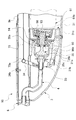
図1は本発明による一実施形態の清掃具の斜視外観図である。図2は前記実施形態による清掃具の斜視分解組立図である。図3は前記実施形態による清掃具の縦断面図である。図4は前記実施形態による清掃具の清掃ヘッドの斜視外観図である。図5は前記実施形態による清掃ヘッドの要部斜視外観図である。図6は前記実施形態による清掃具の把持部の斜視分解組立図である。図7は前記実施形態による把持部の要部拡大断面図である。図8は前記実施形態による把持部の要部拡大断面図である。図9は前記実施形態による清掃具のバルブ開閉装置の要部拡大断面図である。図10は前記実施形態による清掃具のバルブ開閉装置の要部拡大断面図である。図11は、キャップの内部構造を示す構成図である。図12は、キャップ本体の構成を示す概略図である。図13は、バルブハウジング96の構成を示す概略図である。
FIG. 1 is a perspective external view of a cleaning tool according to an embodiment of the present invention. FIG. 2 is an exploded perspective view of the cleaning tool according to the embodiment. FIG. 3 is a longitudinal sectional view of the cleaning tool according to the embodiment. FIG. 4 is a perspective external view of a cleaning head of the cleaning tool according to the embodiment. FIG. 5 is a perspective view showing a main part of the cleaning head according to the embodiment. FIG. 6 is an exploded perspective view of a gripping part of the cleaning tool according to the embodiment. FIG. 7 is an enlarged cross-sectional view of a main part of the grip portion according to the embodiment. FIG. 8 is an enlarged cross-sectional view of a main part of the grip portion according to the embodiment. FIG. 9 is an enlarged cross-sectional view of a main part of the valve opening / closing device of the cleaning tool according to the embodiment. FIG. 10 is an enlarged cross-sectional view of a main part of the valve opening / closing device of the cleaning tool according to the embodiment. FIG. 11 is a configuration diagram showing the internal structure of the cap. FIG. 12 is a schematic view showing the configuration of the cap body. FIG. 13 is a schematic view showing the configuration of the
図14は前記実施形態によるバルブ開閉装置の要部の一部を断面で表した斜視外観図である。図15は前記実施形態によるアダプタと接続機構とを示す斜視外観図である。図16は前記実施形態による第2流通経路の一部を示す斜視外観図である。図17は前記実施形態による第2流通経路の一部を示す斜視外観図である。図18は前記実施形態によるシリンダの斜視外観図である。図19は前記実施形態による第2容器をアダプタに組み付けた状態を示す斜視外観図である。図20は前記実施形態による第2容器をアダプタに組み付けた状態を示す縦断面図である。図21は前記実施形態による第2容器をアダプタに組み付けた状態を示す要部拡大断面図である。図22は別の実施形態の清掃具の要部拡大図である。図23は前記実施形態の要部拡大斜視図である。 FIG. 14 is a perspective external view showing a part of a main part of the valve opening and closing apparatus according to the embodiment. FIG. 15 is a perspective external view showing the adapter and the connection mechanism according to the embodiment. FIG. 16 is a perspective external view showing a part of the second distribution route according to the embodiment. FIG. 17 is a perspective external view showing a part of the second distribution route according to the embodiment. FIG. 18 is a perspective external view of the cylinder according to the embodiment. FIG. 19 is a perspective external view showing a state in which the second container according to the embodiment is assembled to the adapter. FIG. 20 is a longitudinal sectional view showing a state in which the second container according to the embodiment is assembled to the adapter. FIG. 21 is an enlarged cross-sectional view of a main part showing a state in which the second container according to the embodiment is assembled to the adapter. FIG. 22 is an enlarged view of a main part of a cleaning tool according to another embodiment. FIG. 23 is an enlarged perspective view of a main part of the embodiment.
図24は前記実施形態による清掃具の使用状態を示す斜視外観図である。図25は、さらに別の実施形態の清掃具の斜視分解組立図である。図26は、前記実施形態の清掃具の斜視分解組立図である。図27は、前記実施形態の清掃具の縦断面である。図28は、前記実施形態の清掃具のシリンダの斜視図である。図29は、前記実施形態の清掃具のシリンダの斜視図である。図30は、前記実施形態の清掃具の第3容器と第3噴射ノズルの外観図である。図31は、前記実施形態の清掃具の第3容器と第3噴射ノズルの縦断面図である。図32は、前記実施形態の清掃具の第3噴射ノズルの分解斜視外観図である。図33は、前記実施形態の清掃具の第3噴射ノズルの縦断面図である。 FIG. 24 is a perspective external view showing a use state of the cleaning tool according to the embodiment. FIG. 25 is a perspective exploded view of a cleaning tool according to still another embodiment. FIG. 26 is a perspective exploded view of the cleaning tool of the embodiment. FIG. 27 is a longitudinal section of the cleaning tool of the embodiment. FIG. 28 is a perspective view of a cylinder of the cleaning tool of the embodiment. FIG. 29 is a perspective view of a cylinder of the cleaning tool of the embodiment. FIG. 30 is an external view of a third container and a third injection nozzle of the cleaning tool of the embodiment. FIG. 31 is a longitudinal sectional view of a third container and a third injection nozzle of the cleaning tool of the embodiment. FIG. 32 is an exploded perspective external view of a third injection nozzle of the cleaning tool of the embodiment. FIG. 33 is a longitudinal sectional view of a third injection nozzle of the cleaning tool of the embodiment.
図34は、前記実施形態の清掃具の使用状態を示す縦断面図である。図35は、前記実施形態による清掃具の使用状態を示す斜視外観図である。図36は、さらに別の実施形態の清掃具の縦断面図である。図37は、前記実施形態の清掃具の第4噴射ノズルの斜視図である。図38は、前記実施形態の清掃具の第4噴射ノズルの斜視図である。図39は、前記実施形態の清掃具の第4噴射ノズルの縦断面図である。図40は、さらに別の実施形態の清掃具の縦断面図である。 FIG. 34 is a longitudinal sectional view showing a usage state of the cleaning tool of the embodiment. FIG. 35 is a perspective external view showing a use state of the cleaning tool according to the embodiment. FIG. 36 is a longitudinal sectional view of a cleaning tool according to still another embodiment. FIG. 37 is a perspective view of a fourth injection nozzle of the cleaning tool of the embodiment. FIG. 38 is a perspective view of a fourth injection nozzle of the cleaning tool of the embodiment. FIG. 39 is a longitudinal sectional view of a fourth injection nozzle of the cleaning tool of the embodiment. FIG. 40 is a longitudinal sectional view of a cleaning tool according to still another embodiment.
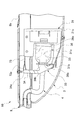
図1、図2又は図3において、清掃具10は、清掃ヘッド2と、清掃ヘッド2の上面に自在継手21を介して連結されたパイプ8と、パイプ8の上端に組み付けられた把持部7とを有している。清掃ヘッド2と把持部7との中間にあるパイプ8にバルブ開閉装置3が設けられている。バルブ開閉装置3には、後述する第1容器61が装着できる。パイプ8は、複数のパイプ材8a、8b、8c、8dを連結したものである。
1, 2, or 3, the
図4において、例えば、清掃ヘッド2の平面形状は長方形となっている。清掃ヘッド2の一方及び他方の長辺にそれぞれ前面2a及び後面2bが形成されている。又、清掃ヘッド2の一方及び他方の短辺にそれぞれ右端面2c及び左端面2dが形成されている。
In FIG. 4, for example, the planar shape of the
清掃ヘッド2は、硬質のホルダ24と、ホルダ24の下面に固着されたパッド25とを有している。ホルダ24は、アクリロニトリル−ブタジエン−スチレン樹脂(ABS)、ポリエチレン樹脂(PE)、ポリプロピレン樹脂(PP)又はポリエチレンテレフタレート樹脂(PET)などの合成樹脂材料で射出成型されている。パッド25は、エチレン−酢酸ビニル共重合体(EVA)、ウレタンなどの発砲樹脂、又はゴムなどの軟質でかつ弾性を発揮する素材で形成されている。パッド25は軟質なPPやPEで形成されてもよい。ホルダ24とパッド25は接着により固定されている。
The cleaning
図5において、パッド25の底面を清掃作業面22としている。清掃作業面22には清掃用シート22aが配置される。清掃作業面22は基本的に平面であるが、清掃作業面22には清掃用シート22aが清掃作業面22に対して滑らないように、多数の小突起が清掃作業面22に一体に形成されてもよい。
In FIG. 5, the bottom surface of the
図4において、ホルダ24の上面には、右端面2cと左端面2dの中間の位置に自在継手21が連結されている。ホルダ24の上面部には、四隅の内側にシート止め機構26が設けられている。シート止め機構26に清掃用シート22aが取り付けられる。シート止め機構26には、ホルダ24の上面に穴26aが形成されている。穴26aはPE・PP・PETなどで形成された変形可能なシート26cで覆われている。シート26cに切れ目26bが形成されており、図5において、清掃用シート22aの一部が切れ目26b内に押し込まれることにより、清掃用シート22aがホルダ24に止められる。
In FIG. 4, the
図4において、ホルダ24には噴液部20が搭載されている。噴液部20は、ホルダ24において、右端面2cと左端面2dとの中間で、かつ自在継手21の前方に配置されている。噴液部20は、台座27と台座27に配置された第1噴射ノズル23とを含む。台座27と第1噴射ノズル23は、ABS・PP・PETなどの合成樹脂で射出成型されている。第1噴射ノズル23は、台座27上に嵌合、接着又はねじ止めなどの手段で固定されている。噴液部20は、台座27と第1噴射ノズル23が一体に形成されていてもよい。
In FIG. 4, the
図4において、ホルダ24の上面には、右端面2cと左端面2dとの中間において、前面2aに向けて解放された凹部24aが形成されている。自在継手21は、凹部24a内に連結されている。噴液部20は、凹部24a内に配置されている。清掃作業面22からその高さ方向に適度に離れた位置において、第1噴射ノズル23の噴射口231から清掃ヘッド2の前方外方へ後述する第1流体を噴射することができる。
In FIG. 4, a
図6において、把持部7は、パイプ8における清掃ヘッド2の対向側に備えられ、又、2つの把持ケース7bを組み合わせて形成されている。把持部7は、バルブ開閉装置3に連結されて、第1容器61の第1バルブ93(図10参照)、又は、後述する第2容器62の第2バルブ62a(図21参照)を開閉させるレバー71を有する。
In FIG. 6, the
図6又は図7において、レバー71は、把持部7に形成された枢軸7cを中心に回動可能に把持部7に支持されている。図8において、使用者がレバー71を角度γだけ引くことができるように、把持部7の内部に備えられたねじりコイルばね75の付勢力によってレバー71の一部が把持部7の内部から外側に向けて突出している。
6 or 7, the
レバー71には、枢軸7cをピッチ円の中心とするギア71aが部分的に形成されている。プーリ74は、把持部7に形成されている枢軸7dの周りを回転可能に組み付けられている。又、プーリ74には、枢軸7dを回転中心とするギア74aが組み付けられている。ギア71aは、レバー71が引かれると、ギア74aに噛み合う。ギア71aは、通常、ギア74aに噛み合っていない。又、プーリ74には、うず巻きコイルばね(図示せず)が内蔵されている。図6又は図7において、このうず巻きコイルばねは、ベルト73の一端を巻いたプーリ74を、ベルト73を巻く方向に回転するように作用する。
The
図7又は図8において、プーリ74は、使用者がレバー71を引いていないときは、うず巻きコイルばねの巻き取り力により、ベルト73を巻き取り、常に、所定の張力をベルト73に付与させている。使用者がレバー71を引くと、ギア71aがギア74aに噛み合うので、プーリ74は、レバー71を引く力とうず巻きコイルばねのテンション力とによってベルト73を巻くことができる。
7 or 8, the
図1及び図2において、パイプ8は清掃ヘッド2と把持部7との中間に、かつ、使用者が位置する側にバルブ開閉装置3を備えている。図9又は図10において、バルブ開閉装置3は、接続機構31と、カム装置33とを有している。接続機構31は第1容器61を着脱自在としている。接続機構31は第1容器61の着脱を容易にするためのカバー31cで覆われている。カム装置33は、角往復運動する動節となる揺り腕34と、揺り腕34に従動して往復直線運動するプッシャ35で構成されている。プッシャ35は、合成樹脂で形成されており、ポンプ36内部に取り付けられている。
1 and 2, the
ポンプ36は、一端側が開口されたU字状の断面を有する形状となっている。ポンプ36の一端側の開口36aは、接続機構31のフレーム31aに気密状態で接続されている。ポンプ36の他端側(底部)には、穴36bが形成されている。穴36bは、第1流通経路を形成するホース4の一端に気密状態で接続している。ホース4の他端は、パイプ8内を通って、第1噴射ノズル23に気密状態で接続している。
The
図9又は図10において、プッシャ35は、第1バルブ93に当接する先端部35aと、ポンプ36の底部の穴36bを塞ぐ鍔部35bを有している。ポンプ36の底部側に取り付けられたリング35cは、揺り腕34の凸部34bに摺動接触する。先端部35aと鍔部35bはいずれもポンプ36内部に位置し、リング35cはポンプ36の外部に位置する。鍔部35bとリング35cとは、ポンプ36を挟んでいる。鍔部35bは、穴36bに向けてポンプ36の弾性力により、穴36bを塞いでいる。先端部35aは開口36aに向いて突出している。
9 or 10, the
揺り腕34は、フレーム31aに設けられた枢軸31bを回転中心として、角往復運動する。移動端34aには、ベルト73の他端側73aが係止されている。したがって、プーリ74から延びるベルト73は、パイプ材8b〜8dの内部を通って、移動端34aに係止されている。揺り腕34には、凸部34b(図9参照)が形成されている。凸部34bは、リング35cに摺動接触可能に、揺り腕34の中間に、リング35c側に突出している。
The
図10において、第1容器61は、第1流体を収容するタンク61bと、タンク61bの開口部に取り付けられているキャップ90と、を有している。キャップ90の先端にはバルブ孔91aが形成されている。
In FIG. 10, the
ここで、キャップ90の内部構造について説明する。図11に示すように、キャップ90は、キャップ本体91と、第1リング部材92と、第1バルブ93と、圧縮コイルばね94と、第2リング部材95と、バルブハウジング96と、シール部材97と、チューブ部材98と、バルブ保護部材99と、バルブ部材100と、で構成されている。
Here, the internal structure of the
図12に示すように、キャップ本体91は、先端部91bと、螺合部91cと、空気孔91dと、を備える。先端部91bの一端には、上述のバルブ孔91aが設けられている。先端部91bは、第1リング部材92と、第1バルブ93と、圧縮コイルばね94と、第2リング部材95と、バルブハウジング96と、シール部材97と、を収容する。螺合部91cは、タンク61bの開口部と螺合する螺号溝が設けられている。空気孔91dは、螺合部91cの上部に設けられた略水平面に設けられている。
As shown in FIG. 12, the
第1リング部材92は、円形状の環状パッキンを有する。第1リング部材92は、第1容器61に封入された第1流体を密封する。第1バルブ93は、ヘッド部93aと脚部93bとを有する。ヘッド部93aは、円筒形のヘッド本体と、ヘッド本体の両端に設けられた一対のフランジ部とを有する。各フランジ部の間、すなわち円筒形状の周面には、上述の第1リング部材92が設けられる。ヘッド部93aの一端は、プッシャ35の一端が挿入される挿入孔が設けられている。ヘッド部93aの他端には、脚部93bが設けられている。脚部93bは、4つの羽根部を備えている。各羽根部には、圧縮コイルばね94を係止する凸部が設けられている。圧縮コイルばね94の一端は、後述する係止溝96eに係止される。一方、圧縮コイルばね94の他端は、凸部に係止される。
The
図13に示すように、バルブハウジング96は、バルブハウジング本体96hと、第1バルブ93が摺動する摺動孔96aと、フランジ部96bと、チューブ部材98を被嵌させる長管96cと、を備える。摺動孔96aは、径の異なる第1摺動孔96a’と第2摺動孔96a’’とを有する。第1摺動孔96a’と第2摺動孔96a’’との間には、係止溝96eが設けられている。第1摺動孔96a’を形成する開口部96fは、キャップ本体91と係合する。開口部96fとフランジ部96bとの間には、第2リング部材95が設けられている。第2リング部材95は、円形状の環状パッキンを有する。第2摺動孔96a’’を形成する他の開口部96gの側部であり、フランジ部96b上には、長管96cが設けられている。長管96cは、空気孔96dを有する。また、フランジ部96bの長管96cが設けられている側には、2つの凸部96iが設けられている。
As shown in FIG. 13, the
図11に示すように、シール部材97は、フランジ部97aを有する。フランジ部97aは、バルブハウジング96のフランジ部96bよりも大きな径を備える。シール部材97は、略中心部に開口部96gを貫通させる嵌通孔97bを備える。また、長管96c及び各凸部96iは、シール部材97を貫通する。ここで、シール部材97は、シリコン樹脂により形成されている。
As shown in FIG. 11, the
チューブ部材98は円柱形状を有する。チューブ部材98の断面形状は、空気孔91dからの空気をタンク61bに流通させることができるように、リング状に形成されている。チューブ部材98の一端は、長管96cに被嵌される。ここで、チューブ部材98は、ポリウレタン樹脂(PU)により形成されている。バルブ保護部材99は、ベル型に形成されている。バルブ保護部材99の上端部には、頂点が嵌通された角部99aが設けられている。角部99aは、チューブ部材98の他端に被嵌される。バルブ保護部材99の上部は、一対の切り欠き部99bを備える。バルブ保護部材99の内部には、バルブ部材100を被嵌するための嵌通孔を有する凸部(図示せず)が設けられている。バルブ部材100は、バルブ保護部材99の内部に設けられている。
The
バルブ部材100は、バルブ本体100aと、フランジ部100bと、を備える。バルブ本体100aは、略円筒形状に形成されている。バルブ本体100aは、弾性部材により形成されている。バルブ本体100aの先端部100cは、円筒形状の両側面から切り落とされた切り削ぎ形状を備えている。ここで、切り削ぎ形状とは、2つの板状の弁が先端部において重着するように配置され、先端略中央部において各弁が開口又は閉口するように構成されたものである。このように構成されることで、先端部100cは、略中央部において各弁が開口し、空気孔91dからの空気をチューブ部材98を介して流通された空気は、タンク61bに空気が送られる。また、バルブ本体100aの他端には、フランジ部100bが設けられている。
The
上記構成により、第1バルブ93がキャップ90の内側から圧縮コイルばね94によって付勢されることにより、バルブ孔91aは、塞がれた状態となる。
With the above configuration, the
また、第1容器61を接続機構31に装着したとき、キャップ90の外周はポンプ36に気密状態で密着するとともに、第1容器61の第1バルブ93は圧縮コイルばね94の付勢力に抗して先端部35aに押圧される。このとき、第1容器61の第1バルブ93はタンク61b側にわずかに移動するが、第1バルブ93とバルブ孔91aとの間には、第1容器61に収容された第1流体の一部がポンプ36と第1バルブ93とによって形成された空間に流れ出るような隙間は形成されない。
When the
このため、第1容器61に収容された第1流体の一部が第1容器61からポンプ36と第1バルブ93とで形成された空間に流れ出ることはない。また、ポンプ36とプッシャ35とによって穴36bは塞がれていることから、この状態では、第1容器61内の第1流体はホース4内に移動することもない。
For this reason, a part of the first fluid stored in the
一方、使用者がレバー71を引くと、ベルト73は把持部7側に移動するので、揺り腕34はベルト73の引っ張り力により回動する。そして、プッシャ35が把持部7側に直線的に移動するので、第1容器61の第1バルブ93がタンク61bのある方向に移動するとともに、鍔部35bがポンプ36の穴36bから離れる方向に移動する。したがって、鍔部35bと穴36bとの間に隙間が生じると同時に、空気孔91dから吸入された空気がチューブ部材98及びバルブ部材100を介してタンク61b内部に供給される。これにより、第1容器61の第1流体がこの隙間及びホース4を通って第1噴射ノズル23に供給される。供給された第1流体は第1噴射ノズル23から清掃ヘッド2の前方に噴射される。すなわち、第1流通経路を第1流体が移動する。
On the other hand, when the user pulls the
図14において、バルブ開閉装置3は、第1容器61の代わりにアダプタ32を介して第2容器62を取り付けることができる。アダプタ32は、筒状のアダプタ本体32aと、このアダプタ本体32aの内部に軸線方向に移動可能に保持されるシリンダ32bと、このシリンダ32bに連結される第2噴射ノズル51とを有している。そして、第2噴射ノズル51を第2流体が移動する第2流通経路としている。
In FIG. 14, the valve opening /
図15において、アダプタ本体32aは、一端に第1容器61のキャップ90とほぼ同じ形状の凸部321を有する。図14において、凸部321の中央には、プッシャ35の先端部35aが非接触で出入りすることができる大きさの第1接続口32cが形成されている。図20において、アダプタ本体32aの他端側は、第2容器62を着脱自在に保持する第2接続口32dを有している。アダプタ本体32aの第2接続口32d側の側面には、第2噴射ノズル51の噴射口51cをアダプタ本体32aの外に配置するための開口32g(図19参照)が形成されている。図24において、噴射口51cの位置は、清掃作業面22(図3参照)から約50cmから80cmの範囲の距離であることが好ましく、噴射口51cの位置は、清掃作業面22から70cm程度の距離であることがより好ましい。したがって、図24に示されるように、例えば、清掃具10を略45度の角度に傾斜させて使用している状態において、噴射口51cの床面Fからの高さHは、床面Fから40cmから60cmの範囲であること、を可能とし、高さHをより好ましい50cm程度とすることを可能とする。
In FIG. 15, the adapter
図18において、シリンダ32bの一端には、シリンダ32bの軸線と直交する方向に延びる鍔部323が形成されている。図21において、シリンダ32bの他端側は、第2接続口32dに向かって軸線方向と鋭角に交わる傾斜部32eを有している。軸線方向と傾斜部32eとの交差角度は、30〜60度の範囲内が好ましい。シリンダ32bは、傾斜部32eの両側部に間隔をおいて配置される一対の側壁32fを有している。図20において、シリンダ32bの中央には、アダプタ本体32aの段部325に内部からの当接可能な鍔部324が一体的に形成されている。
In FIG. 18, a
図16又は図17において、第2噴射ノズル51は本体部511とノズル部512とを有する。第2噴射ノズル51は、本体部511とノズル部512とが組み付けられて、T字状に形成されている。図16又は図19において、本体部511の一端51aが傾斜部32eに接触している。本体部511の他端51bは第2バルブ62aに接続されている。本体部511の接続端51eはノズル部512に接続されている。図17において、このT字状の第2噴射ノズル51のT字端にアダプタ本体32aの外になるような位置に第2流体を噴射する噴射口51cが設けられている。第2バルブ62aの一部は、一対の側壁32fの間隔内に配置されている。
In FIG. 16 or FIG. 17, the
図14において、シリンダ32b及び第2噴射ノズル51はアダプタ本体32aの内部に第2接続口32dから収容される。アダプタ本体32aの一端は、第1容器61のキャップ90とほぼ同じ形状を有しているから、アダプタ本体32aの一端は接続機構31のポンプ36に嵌合されて、アダプタ本体32aは接続機構31に保持される。このとき、噴射口51cは、開口32gから突出している(図19参照)。噴射口51cは、清掃ヘッド2の前後方向において、第1噴射ノズル23と反対側である後方に噴射することができるように、開口32gから突出している。
In FIG. 14, the
アダプタ本体32aの第2接続口32d側には、第2容器62が装着される。第2容器62は、第2バルブ62aの軸線と直交する方向に傾動させて第2容器62に収容された第2流体を噴射させるチルトタイプのバルブを備えたスプレー缶である。したがって、第2噴射ノズル51が傾動すると、第2流体が噴射口51cから噴射される。又、噴射口51cが床面Fから高さHに位置しているから、噴射口51cから噴射される第2流体は、粘性の低い水のような流体以外に、粘性の高い流体、たとえば、泡などを噴射口51cから噴射させることができる。
A
例えば、第1容器61は、第1バルブ93(図10参照)の軸線と平行する方向に移動させて第1流体を自然落下させるボトルタイプであってよい。例えば、第1流体としては、水、液体洗剤又は液体ワックスが用いられる。第2流体としては、乾燥後に常温で固形となるアクリル樹脂系、ポリエチレンワックスなどの合成ワックス、又は、カルナバワックスのような天然ワックスなどのつや出し剤が採用される。これらのワックスすなわちつや出し剤を採用することにより、床面への塗工又は払拭が簡便になる。
For example, the
使用者がレバー71を引くと、レバー71は、ねじりコイルばね75の付勢力に抗して把持部7の内部に押し込まれ、ギア71aを回動させる。これにより、ギア74aがプーリ74とともに回動し、ベルト73を巻き取る。ベルト73がプーリ74に巻き取られると、プッシャ35がシリンダ32bを第2容器62側に移動させる。
When the user pulls the
シリンダ32bが第2容器62側に移動すると、傾斜部32eが第2噴射ノズル51をシリンダ32bの移動方向に直交する方向に傾動させる。図24において、これにより、第2容器62の内部にある第2流体を第2噴射ノズル51の噴射口51cから清掃ヘッド2の後方に噴射させることができる。
When the
使用者がレバー71を引くことをやめると、レバー71は、ねじりコイルばね75の付勢力によって、プーリ74をベルト73が巻き解かれる方向に回動させる。これによって、プッシャ35がシリンダ32bから離れる方向に移動して、シリンダ32bを押す力は作用しなくなる。そして、第2容器62の第2バルブ62aの復帰力が、シリンダ32bの傾斜部32eに作用する。そして、シリンダ32bは、第2容器62から離れる方向に移動する。そして、第2容器62に対する第2バルブ62aの傾きが垂直状態に復帰し、第2噴射ノズル51からの第2流体の噴射が停止する。
When the user stops pulling the
図22及び図23に示された別の実施形態では、第2噴射ノズル51は、L字状部51hと、このL字状部51hに形成され、第2バルブ62aの軸線と直交する方向に伸びる鍔51fとを有している。又、シリンダ32bの他端側は、鍔51fにおいて第2バルブ62aから離れた位置を押すことが可能な突起部32hを有している。L字状部51hの一端が第2バルブ62aに連結し、L字状部51hの他端にアダプタ本体32aの外の位置に第2流体を噴射する噴射口51cが設けられている。
In another embodiment shown in FIGS. 22 and 23, the
突起部32hが接触する鍔51fの面は、第2バルブ62aが傾動する回転中心Pから軸線方向において距離hだけ離れている。又、突起部32hは第2バルブ62aから、軸線方向から離れる方向において間隔を置いた位置の鍔51fと接触している。このため、シリンダ32bの往復運動は、回転中心Pを中心とする回転運動に変換され、第2バルブ62aはその回転運動によって角度αだけ傾動する。
The surface of the
図25に示された更に別の実施形態では、バルブ開閉装置3は、第1容器61の代わりにアダプタ120を介して第3容器63を取り付けることができる。第3容器63は、第3バルブ63aの軸線と直交する方向に傾動させて第3容器63に収容された第3流体を噴射させるチルトタイプのバルブを備えたスプレー缶である。本実施例では、第3容器63には、ワックスのような第3流体が入っている。
In still another embodiment shown in FIG. 25, the valve opening /
アダプタ120は、筒状のアダプタ本体130と、このアダプタ本体130の内部に軸線方向に移動可能に保持されるシリンダ140と、このシリンダ140に連結される第3噴射ノズル150とを有している。そして、第3噴射ノズル150は第3流体が移動する第2流通経路として作用する。
The
図25、図26又は図27において、アダプタ本体130は、筒状の本体部131と、本体部131の一端を第1容器61のキャップ90とほぼ同じ形状の凸部132と、本体部131の他端に第3容器63を着脱自在に保持する第3接続口133と、第3接続口133の近傍に、第3噴射ノズル150を筒状の内部からアダプタ本体130の外に導くための開口134とを形成している。
25, 26, or 27, the adapter
凸部132の中央には、プッシャ35の先端部35aが非接触で出入りすることができる大きさの第4接続口135が形成されている。第4接続口135は、本体部131の筒状内面136に接続している。また、筒状内面136は開口134に接続している。筒状内面136には、軸線方向に伸びる筒状内面136に形成された溝が形成されている。
In the center of the
図27、図28又は図29において、シリンダ140は、4つの板状部材141aを十字状に組み合わせたシリンダ本体部141と、シリンダ本体部141の一端に形成された鍔部142と、鍔部142より小径であり、鍔部142に形成された支持部143を介して形成された鍔部144と、鍔部144に形成された支持部145を介して形成された鍔部146と、シリンダ本体部141の他端に形成された鍔部147と、鍔部147に形成された一対の押圧部148a、148bとを有する。
In FIG. 27, FIG. 28 or FIG. 29, the
一対の押圧部148a、148bは、いずれも、中心よりずれた位置に頂点を有するほぼ三角板状の形状を有し、これらの間に第3噴射ノズル150を配置可能な隙間をおいて、鍔部147に形成されている(図26参照)。鍔部144は、アダプタ本体130の段部137に内部からの当接可能な形状を有している。また、鍔部142は、アダプタ本体130の筒状内面136に摺動可能な形状を有している。
Each of the pair of
図30、図31又は図32において、第3噴射ノズル150は本体部151とアーム部152とノズル部153とを有する。本体部151は、2つのパイプ形状部151a、151bがほぼ直角に交差したT字状に形成されている。パイプ形状部151bの一方の端部から、鍔部154a、145bが伸びている。また、パイプ形状部151aの内周面には軸線方向に伸びる溝部151dが形成されている。
30, 31, or 32, the
パイプ形状部151bの端部には、第3容器63の第3バルブ63aが嵌合可能な嵌合穴151fが形成さている。嵌合穴151fは本体部151を貫通する貫通穴151eに接続している。貫通穴151eの一方の開口側は、アーム部152の嵌合部152hが嵌合可能な嵌合部151cが形成されている。アーム部152は、2つのパイプ形状部152a、152bが交差したほぼL字形状に形成され、また、貫通穴152gを有している。パイプ形状部152aの外周面には、凸部152e(図30参照)が形成されている。パイプ形状部152aの端部は、凸部152eが溝部151dに嵌合するように、パイプ形状部151aに嵌合される嵌合部152hを有する。これにより、パイプ形状部152aとパイプ形状部151aとは、相対的な位置関係を確定させ、さらに、貫通穴151eと貫通穴152gとを気密的に接続することができる。
A
パイプ形状部152bの端部の周囲には、リング状の凸部152fが形成されている。また、パイプ形状部152aのパイプ形状部152b側には、凹部152dが形成されている。
A ring-shaped
図33において、ノズル部153は、中空のパイプ形状の貫通穴153eを有するノズル本体部153aと、この一端に形成され、貫通穴153eに接続している噴射口153dとを有する。ノズル本体部153aの他端は開放されており、嵌合口153bを形成している。嵌合口153bの周囲の一部には、凹部152dに嵌合することができる凸部153fが形成されている。嵌合口153bの中央には、凸部152fと嵌め合うことができる溝153cが形成されている。これにより、ノズル部153は、アーム部152に対する相対的な位置関係を確定させ、さらに、アーム部152の貫通穴152gと貫通穴153eとを気密的に接続することができる。
33, the
図31において、第3噴射ノズル150は、第3容器63の第3バルブ63aから噴射口153dまでを気密的に接続して、第2流通経路を形成している。したがって、第3バルブ63aから噴出されるワックスのような液体を噴射口153dから噴射させることができる。
In FIG. 31, the
図25又は図26において、シリンダ140はアダプタ本体130の内部に第3接続口133から収容される。シリンダ140は、鍔部142及び鍔部147が筒状内面136において軸線方向に摺動可能な状態に維持される。また、シリンダ140は、板状部材141aが軸線方向に伸び、筒状内面136に形成された溝(図示せず)に摺動可能に配置される。これにより、シリンダ140は、筒状内面136内において、軸線方向には、移動することができる状態に置かれるが、軸線方向を回転中心とする回転をすることができない状態に置かれる。さらに、シリンダ140の鍔部146は、第4接続口135の近傍に位置する(図27参照)。
In FIG. 25 or FIG. 26, the
本体部151とアーム部152とノズル部153とで組み立てられた第3噴射ノズル150の嵌合穴151fは、第3容器63の第3バルブ63aに気密的に嵌合される(図31参照)。
The
図31において、第3容器63は、アダプタ本体130の第3接続口133に嵌合され保持される。このとき、第3噴射ノズル150の噴射口153dは、開口134から突出している。第3噴射ノズル150は、清掃ヘッド2の前後方向において、第1噴射ノズル23と反対側である後方に噴射することができるように、開口134から突出している。
In FIG. 31, the
アダプタ本体130の一端は、第1容器61のキャップ90とほぼ同じ形状を有しているから、接続機構31のポンプ36に嵌合されるので、アダプタ本体130は接続機構31に保持される。
Since one end of the
図34において、シリンダ140の一対の押圧部148a、148bの頂点は、それぞれ、鍔部154a、154b(図25又は図26参照)を押すことができる位置に配置される。
In FIG. 34, the vertices of the pair of
使用者がレバー71を引くと、レバー71は、ねじりコイルばね75の付勢力に抗して把持部7の内部に押し込まれ、ギア71aを回動させる。これにより、ギア74aがプーリ74とともに回動し、ベルト73を巻き取る。ベルト73がプーリ74に巻き取られると、プッシャ35がシリンダ140の鍔部146に形成された凹部146aを押し、シリンダ140を第3容器63側に移動させる。
When the user pulls the
図34において、シリンダ140が第3容器63側に移動すると、一対の押圧部148a、148bは、それぞれ、鍔部154a、154bを押し、ひいては、第3バルブ63aを傾斜させる。これにより、第3容器63の内部にある第3流体を第3噴射ノズル150の噴射口153dから清掃ヘッド2の後方に噴射させることができる。
In FIG. 34, when the
したがって、図33において、第3噴射ノズル150が傾動すると、第3流体が噴射口153dから噴射される。又、噴射口153dが床面Fから高さHに位置しているから、噴射口153dから噴射される第3流体は、粘性の低い水のような流体以外に、粘性の高い流体、たとえば、泡などを噴射口153dから噴射させることができる。具体的には、噴射口153dの位置は、清掃作業面22からの高さH(図35参照)が約50cmから80cmの範囲となる距離であることが好ましく、噴射口153dの位置は、清掃作業面22から70cm程度の距離であることがより好ましい。したがって、例えば、清掃具10を略45度の角度に傾斜させて使用している状態において、噴射口153dの床面Fからの高さHは、床面Fから40cmから60cmの範囲であること、を可能とし、高さHをより好ましい50cm程度とすることを可能とする。
Therefore, in FIG. 33, when the
図35は、パイプ8の長さが1145mmで、パイプ8と床面Fとの角度が60度であり、チルトタイプのバルブを備えた第3容器63を用いたとき、第3噴射ノズル150の噴射口153dから噴射されるワックスの最小噴射範囲と最大噴射範囲とを試算し、試算した結果を点P3と点P4と表している。この場合、最小とはレバー71を引く力が20Nの時、ちょうどチルトタイプのバルブを備えたエアゾール缶(第3容器63)の第3バルブ63aが開き始めた状態を示し、最大とはレバー71を引く力が24Nの時、第3バルブ63aが最大限に開いた状態を示している。
In FIG. 35, when the length of the
また、図面中の点P1及び点P2は、床面Fとパイプ8との角度が45度の場合を想定したもので、点P1はレバー71を弱く引いて、ちょうど第3バルブ63aが開き始めた時の内容物着地点を示している。点P2はレバー71を最大限に引いて、第3バルブ63aが最大限に開いた時の内容物着地点を示している。
Also, the points P1 and P2 in the drawing are based on the assumption that the angle between the floor surface F and the
使用者がレバー71を引くことをやめると、レバー71は、ねじりコイルばね75の付勢力によって、プーリ74をベルト73が巻き解かれる方向に回動させる。これによって、プッシャ35がシリンダ140から離れる方向に移動して、シリンダ140を押す力は作用しなくなる。そして、第3容器63の第3バルブ63aの復帰力が、シリンダ140の一対の押圧部148a、148bに作用する。そして、シリンダ140は、第3容器63から離れる方向に移動する。そして、第3容器63に対する第2バルブ62aの傾きが垂直状態に復帰し、第3噴射ノズル150からの第2流体の噴射が停止する。
When the user stops pulling the
図36に示された更に別の実施形態では、第3容器63に、第3噴射ノズル150の代わりに第4噴射ノズル160を設けた。第4噴射ノズル160は、概ねハンマーのような形状を有しており、第3噴射ノズル150のアーム部152及びノズル部153の代わりに支持部162及びノズル部163で構成されている。
In still another embodiment shown in FIG. 36, a
図37において、支持部162は、貫通穴162bを有する円筒状部162aとヘッド部162fとが交差して形成されている。円筒状部162aの外周に軸線方向に伸びる凸部162eが形成されている。この凸部162eは溝部151dに係合し、ヘッド部162fの一方の端部162hは嵌合部151cに嵌合する。ヘッド部162fの他方の端部にはヘッド部162fが形成されている。ヘッド部162fには、くさび形の内側面162jが形成されており、その底部は開口162kを形成している。また、貫通穴162bは内側面162jに接続している。
In FIG. 37, the
図38において、くさび形状を有するノズル部163は、くさび部163aと板部163bとを有している。くさび部163aの一方の面に溝163cが形成されており、その溝163cは、くさび部163aの先端面に繋がっている。くさび部163aの他方の面には、凹部163dが形成されている。
38, the
図39において、第4噴射ノズル160は、ノズル部163のくさび部163aをヘッド部162fの内側面126jに圧入して形成される。これにより、溝163cとヘッド部162fの内側面162jとにより、貫通穴152gに連通する第4流通経路の一部を形成する。つまり、貫通穴162bを流れる流体は溝163cの底部に当たり、その流れる方向を開口162kに向け、開口162kから噴射する。
In FIG. 39, the
図40において、アダプタ121は、チルトタイプのバルブを備えた第3容器63の代わりにプレスダウンタイプのバルブを備えた第4容器64を用いている。また、シリンダ140’は、鍔部147の中央に凸部149を設けている。シリンダ140’が軸線方向(矢印方向)に移動すると、凸部149は、第3噴射ノズル150を押すので、第4容器64の内容物が第3噴射ノズル150の噴射口153dから噴射される。したがって、プレスダウンタイプのバルブを備えた第4容器64を用いた清掃具10は、第3噴射ノズルの角度が変化しないため、清掃中にレバー71の引き具合が変化しても、一定の範囲を噴射することができる。
In FIG. 40, the
2 清掃ヘッド
3 バルブ開閉装置
7 把持部
8 パイプ
10 清掃具
20 噴液部
22 清掃作業面
23 第1噴射ノズル
31 接続機構
32 アダプタ
51 第2噴射ノズル
61 第1容器
93 第1バルブ
62 第2容器
62a 第2バルブ
63 第3容器
63a 第3バルブ
64 第4容器
71 レバー
120、121 アダプタ
133 第3接続口
134 開口
135 第4接続口
136 筒状内面
140、140’ シリンダ
150 第3噴射ノズル
160 第4噴射ノズル
DESCRIPTION OF
Claims (11)
前記バルブ開閉装置は、前記第1容器が着脱自在な接続機構と、この接続機構に連結されて前記第2容器が着脱自在なアダプタと、を備え、
前記清掃ヘッドは、前記第1流体を前記接続機構から当該清掃ヘッドの外へ噴射する第1噴射ノズルを有し、
前記アダプタは、前記第2流体を当該アダプタから噴射する第2噴射ノズルを有し、
前記把持部は、前記バルブ開閉装置に連結されて、前記第1容器の第1バルブ、又は、前記第2容器の第2バルブを開閉させるレバーを有する清掃具。 A cleaning head having a cleaning work surface at the bottom, a gripping portion provided on the opposite side of the cleaning head, a pipe connecting the cleaning head and the gripping portion, and a first fluid provided in the pipe and containing a first fluid. A valve opening and closing device capable of holding a container or a second container containing a second fluid ,
The valve opening and closing device includes a connection mechanism in which the first container is detachable, and an adapter connected to the connection mechanism and in which the second container is detachable,
The cleaning head has a first injection nozzle that injects the first fluid from the connection mechanism to the outside of the cleaning head,
The adapter has a second injection nozzle that injects the second fluid from the adapter,
The gripping part is connected to the valve opening / closing device, and has a lever that opens and closes the first valve of the first container or the second valve of the second container .
前記把持部は、前記レバーの回動運動に連動して回動されるプーリを有し、
ベルトの一端側が前記揺り腕の移動端に係止され、このベルトの他端側がプーリに巻き掛けされ、前記レバーの変位を前記プッシャに伝達する請求項1から7のいずれかに記載の清掃具。 The connection mechanism comprises a cam device having a swinging arm that serves as a node that reciprocates angularly, and a pusher that reciprocates linearly following the swinging arm,
The gripping portion has a pulley that is rotated in conjunction with the rotational movement of the lever,
The cleaning tool according to any one of claims 1 to 7, wherein one end side of the belt is locked to a moving end of the swing arm, and the other end side of the belt is wound around a pulley to transmit displacement of the lever to the pusher. .
前記アダプタ本体の一端側は、前記接続機構に着脱自在に保持される第1接続口を有し、前記アダプタ本体の他端側は、前記第2容器を着脱自在に保持する第2接続口を有し、
前記シリンダの一端側は、前記第1接続口に向かって前記プッシャの先端部に当接され、前記シリンダの他端側は、前記第2接続口に向かって軸線方向と鋭角に交わる傾斜部を有し、
前記第2噴射ノズルはT字状に形成され、このT字状の第2噴射ノズルの一端が前記傾斜部に連結し、このT字状の第2噴射ノズルの他端が前記第2バルブに接続され、このT字状の第2噴射ノズルのT字端に前記アダプタ本体の外に前記第2流体を噴射する噴射口が設けられている請求項8記載の清掃具。 The adapter includes a cylindrical adapter main body, a cylinder held in the main body so as to be movable in the axial direction, and the second injection nozzle connected to the cylinder.
One end side of the adapter body has a first connection port detachably held by the connection mechanism, and the other end side of the adapter body has a second connection port detachably holding the second container. Have
One end of the cylinder is in contact with the tip of the pusher toward the first connection port, and the other end of the cylinder has an inclined portion that intersects the axial direction and an acute angle toward the second connection port. Have
The second injection nozzle is formed in a T-shape, one end of the T-shaped second injection nozzle is connected to the inclined portion, and the other end of the T-shaped second injection nozzle is connected to the second valve. The cleaning tool according to claim 8, wherein an injection port for injecting the second fluid to the outside of the adapter body is provided at a T-shaped end of the T-shaped second injection nozzle.
前記一対の側壁は、前記第2バルブの一部が前記間隔内に配置されている請求項9記載の清掃具。 The cylinder has a pair of side walls disposed at intervals on both sides of the inclined portion,
The cleaning tool according to claim 9, wherein a part of the second valve is disposed in the interval between the pair of side walls.
Priority Applications (5)
| Application Number | Priority Date | Filing Date | Title |
|---|---|---|---|
| JP2006007997A JP4734124B2 (en) | 2005-04-05 | 2006-01-16 | Cleaning tool |
| PCT/JP2006/305048 WO2006109388A1 (en) | 2005-04-05 | 2006-03-14 | Cleaning tool |
| US11/386,829 US7708485B2 (en) | 2005-04-05 | 2006-03-23 | Cleaning implement |
| TW095110117A TW200711617A (en) | 2005-04-05 | 2006-03-23 | Cleaner |
| ARP060101284A AR052737A1 (en) | 2005-04-05 | 2006-03-31 | CLEANING IMPLEMENT |
Applications Claiming Priority (3)
| Application Number | Priority Date | Filing Date | Title |
|---|---|---|---|
| JP2005108307 | 2005-04-05 | ||
| JP2005108307 | 2005-04-05 | ||
| JP2006007997A JP4734124B2 (en) | 2005-04-05 | 2006-01-16 | Cleaning tool |
Publications (2)
| Publication Number | Publication Date |
|---|---|
| JP2006312022A JP2006312022A (en) | 2006-11-16 |
| JP4734124B2 true JP4734124B2 (en) | 2011-07-27 |
Family
ID=37086680
Family Applications (1)
| Application Number | Title | Priority Date | Filing Date |
|---|---|---|---|
| JP2006007997A Expired - Fee Related JP4734124B2 (en) | 2005-04-05 | 2006-01-16 | Cleaning tool |
Country Status (5)
| Country | Link |
|---|---|
| US (1) | US7708485B2 (en) |
| JP (1) | JP4734124B2 (en) |
| AR (1) | AR052737A1 (en) |
| TW (1) | TW200711617A (en) |
| WO (1) | WO2006109388A1 (en) |
Families Citing this family (32)
| Publication number | Priority date | Publication date | Assignee | Title |
|---|---|---|---|---|
| US8079770B2 (en) | 2006-10-26 | 2011-12-20 | Diversey, Inc. | Cleaning tool with fluid delivery device |
| USD602664S1 (en) | 2007-05-03 | 2009-10-20 | Johnsondiversey, Inc. | Floor maintenance tool |
| USD590117S1 (en) | 2007-05-03 | 2009-04-07 | Johnsondiversey, Inc. | Floor maintenance tool |
| CN101801253B (en) * | 2007-08-07 | 2013-06-12 | 碧洁家庭护理有限公司 | Surface treating implement |
| GB0913488D0 (en) * | 2009-08-01 | 2009-09-16 | Reckitt Benckiser Nv | Product |
| US8834053B2 (en) * | 2009-09-17 | 2014-09-16 | Rubbermaid Commercial Products, Llc | Mop handle grip and thumb trigger mechanism |
| US9011033B2 (en) * | 2010-02-04 | 2015-04-21 | Lawrence Orubor | Combined hand held surface cleaning and powered spray device |
| GB201101006D0 (en) * | 2011-01-21 | 2011-03-09 | Reckitt Benckiser Nv | Product |
| US9113771B2 (en) | 2011-06-24 | 2015-08-25 | S. C. Johnson & Son, Inc. | Cleaning system with attachable dispenser |
| CN202604727U (en) * | 2012-05-14 | 2012-12-19 | 苏州市洁宝王电器有限公司 | Electric cleaning device |
| CN208319154U (en) | 2014-08-27 | 2019-01-04 | 创科实业有限公司 | For spraying the reservoir pintle assembly and sprinkling mop of mop |
| US9877631B2 (en) | 2015-06-26 | 2018-01-30 | Unger Marketing International, Llc | Hard surface cleaning devices |
| US10973387B2 (en) | 2015-06-26 | 2021-04-13 | Unger Marketing International, Llc | Multi-orientation cleaning device |
| US20170049292A1 (en) | 2015-08-17 | 2017-02-23 | Unger Marketing International, Llc | Hard surface cleaning and conditioning assemblies |
| US20190001480A1 (en) | 2015-08-17 | 2019-01-03 | Unger Marketing International, Llc | Tool handles having stationary and rotational portions |
| USD769129S1 (en) | 2015-09-21 | 2016-10-18 | Unger Marketing International, Llc | Flexible pouch |
| USD852444S1 (en) | 2016-08-16 | 2019-06-25 | Unger Marketing International, Llc | Bottle |
| USD864511S1 (en) | 2016-08-16 | 2019-10-22 | Unger Marketing International, Llc | Pole grip |
| JP6425285B2 (en) * | 2016-08-31 | 2018-11-21 | 嘉興捷順旅遊製品有限公司JIAXING JACKSON TRAVEL PRODUCTS Co.,Ltd. | Fountain mop |
| DE202017104994U1 (en) * | 2016-08-31 | 2017-09-18 | Jiaxing Jackson Travel Products Co., Ltd. | Spray Mop |
| USD840625S1 (en) | 2016-09-14 | 2019-02-12 | Unger Marketing International, Llc | Hard surface cleaning device |
| USD840626S1 (en) | 2016-09-14 | 2019-02-12 | Unger Marketing International, Llc | Hard surface cleaning device |
| EP3512400A4 (en) | 2016-09-14 | 2020-06-03 | Unger Marketing International, LLC | Hard surface cleaning devices |
| USD850883S1 (en) | 2016-10-17 | 2019-06-11 | Unger Marketing International, Llc | Tool handle |
| USD848093S1 (en) | 2016-10-17 | 2019-05-07 | Unger Marketing International, Llc | Hard surface cleaning device |
| US10682034B2 (en) * | 2017-07-13 | 2020-06-16 | Geerpres, Inc. | Cleaning device having fluid reservoir handle with integral refill/reservoir receiver |
| USD867705S1 (en) | 2017-09-11 | 2019-11-19 | Unger Marketing International, Llc | Bottle |
| USD866899S1 (en) | 2017-09-11 | 2019-11-12 | Unger Marketing International, Llc | Tool grip |
| USD881494S1 (en) | 2017-09-11 | 2020-04-14 | Unger Marketing International, Llc | Tool grip |
| USD904704S1 (en) | 2018-03-14 | 2020-12-08 | Unger Marketing International, Llc | Hard surface cleaning device |
| USD911844S1 (en) | 2019-01-18 | 2021-03-02 | Unger Marketing International, Llc | Bottle for a cleaning device |
| KR200491615Y1 (en) * | 2019-03-28 | 2020-05-11 | 김예진 | Table cleaner |
Family Cites Families (14)
| Publication number | Priority date | Publication date | Assignee | Title |
|---|---|---|---|---|
| JPS5018358Y1 (en) | 1969-02-12 | 1975-06-05 | ||
| JPS5018358A (en) * | 1973-06-11 | 1975-02-26 | ||
| DE3718141A1 (en) * | 1987-05-29 | 1988-12-08 | Henkel Kgaa | DEVICE FOR APPLYING FLOOR CLEANING AND MAINTENANCE PRODUCTS |
| JPS645515U (en) | 1987-06-30 | 1989-01-12 | ||
| DE69629101T2 (en) * | 1996-02-13 | 2004-02-12 | JohnsonDiversey, Inc., Sturtevant | Method and device for surface treatment |
| US6206058B1 (en) * | 1998-11-09 | 2001-03-27 | The Procter & Gamble Company | Integrated vent and fluid transfer fitment |
| WO2004021852A2 (en) * | 2002-09-09 | 2004-03-18 | The Procter & Gamble Company | Device for remotely actuating a mechanism |
| US20040141797A1 (en) * | 2003-01-16 | 2004-07-22 | Aram Garabedian | Advanced aerosol cleaning system |
| US6953299B2 (en) * | 2003-01-16 | 2005-10-11 | The Clorox Company | Cleaning implement with interchangeable tool heads |
| JP4230818B2 (en) | 2003-05-16 | 2009-02-25 | 花王株式会社 | Cleaning tool |
| JP4072517B2 (en) | 2004-06-03 | 2008-04-09 | ユニ・チャーム株式会社 | Cleaning tool |
| JP4098749B2 (en) | 2004-06-03 | 2008-06-11 | ユニ・チャーム株式会社 | Cleaning tool with fountain device |
| JP4098750B2 (en) | 2004-06-03 | 2008-06-11 | ユニ・チャーム株式会社 | Cleaning tool with fountain device |
| US6960042B1 (en) * | 2005-01-18 | 2005-11-01 | Tien Jong Hsiao | Versatile mop |
-
2006
- 2006-01-16 JP JP2006007997A patent/JP4734124B2/en not_active Expired - Fee Related
- 2006-03-14 WO PCT/JP2006/305048 patent/WO2006109388A1/en active Application Filing
- 2006-03-23 US US11/386,829 patent/US7708485B2/en not_active Expired - Fee Related
- 2006-03-23 TW TW095110117A patent/TW200711617A/en not_active IP Right Cessation
- 2006-03-31 AR ARP060101284A patent/AR052737A1/en active IP Right Grant
Also Published As
| Publication number | Publication date |
|---|---|
| JP2006312022A (en) | 2006-11-16 |
| TW200711617A (en) | 2007-04-01 |
| US7708485B2 (en) | 2010-05-04 |
| US20060269353A1 (en) | 2006-11-30 |
| TWI314447B (en) | 2009-09-11 |
| AR052737A1 (en) | 2007-03-28 |
| WO2006109388A1 (en) | 2006-10-19 |
Similar Documents
| Publication | Publication Date | Title |
|---|---|---|
| JP4734124B2 (en) | Cleaning tool | |
| JP4734123B2 (en) | Cleaning tool | |
| JP4890865B2 (en) | Cleaning tool | |
| KR100758521B1 (en) | Fluid transfer fitment | |
| CN107997841B (en) | Cleaning implement | |
| US8152400B2 (en) | Surface cleaner with removable wand | |
| AU2017351942B2 (en) | Cleaning appliance | |
| US20070081850A1 (en) | Apparatus and method for a fluid dispensing brush | |
| WO2018083445A1 (en) | Cleaning appliance | |
| US20200261933A1 (en) | Paint sprayer | |
| US20180028039A1 (en) | Liquid dispensing cleaning system and methods of use | |
| EP3718642B1 (en) | Invertible hand held trigger sprayer | |
| WO2018083446A1 (en) | Cleaning appliance | |
| JP2009034499A (en) | Scrubber with detergent vessel, and detergent supply system therefor |
Legal Events
| Date | Code | Title | Description |
|---|---|---|---|
| A621 | Written request for application examination |
Free format text: JAPANESE INTERMEDIATE CODE: A621 Effective date: 20081128 |
|
| A131 | Notification of reasons for refusal |
Free format text: JAPANESE INTERMEDIATE CODE: A131 Effective date: 20100831 |
|
| A521 | Written amendment |
Free format text: JAPANESE INTERMEDIATE CODE: A523 Effective date: 20101101 |
|
| TRDD | Decision of grant or rejection written | ||
| A01 | Written decision to grant a patent or to grant a registration (utility model) |
Free format text: JAPANESE INTERMEDIATE CODE: A01 Effective date: 20110329 |
|
| A61 | First payment of annual fees (during grant procedure) |
Free format text: JAPANESE INTERMEDIATE CODE: A61 Effective date: 20110425 |
|
| FPAY | Renewal fee payment (event date is renewal date of database) |
Free format text: PAYMENT UNTIL: 20140428 Year of fee payment: 3 |
|
| R150 | Certificate of patent or registration of utility model |
Free format text: JAPANESE INTERMEDIATE CODE: R150 Ref document number: 4734124 Country of ref document: JP Free format text: JAPANESE INTERMEDIATE CODE: R150 |
|
| R250 | Receipt of annual fees |
Free format text: JAPANESE INTERMEDIATE CODE: R250 |
|
| R250 | Receipt of annual fees |
Free format text: JAPANESE INTERMEDIATE CODE: R250 |
|
| R250 | Receipt of annual fees |
Free format text: JAPANESE INTERMEDIATE CODE: R250 |
|
| R250 | Receipt of annual fees |
Free format text: JAPANESE INTERMEDIATE CODE: R250 |
|
| R250 | Receipt of annual fees |
Free format text: JAPANESE INTERMEDIATE CODE: R250 |
|
| R250 | Receipt of annual fees |
Free format text: JAPANESE INTERMEDIATE CODE: R250 |
|
| R250 | Receipt of annual fees |
Free format text: JAPANESE INTERMEDIATE CODE: R250 |
|
| LAPS | Cancellation because of no payment of annual fees |