EP2665279A1 - Polarizing stereo electronic large screen display system and manufacturing method thereof - Google Patents
Polarizing stereo electronic large screen display system and manufacturing method thereof Download PDFInfo
- Publication number
- EP2665279A1 EP2665279A1 EP12734712.8A EP12734712A EP2665279A1 EP 2665279 A1 EP2665279 A1 EP 2665279A1 EP 12734712 A EP12734712 A EP 12734712A EP 2665279 A1 EP2665279 A1 EP 2665279A1
- Authority
- EP
- European Patent Office
- Prior art keywords
- display
- polarizing
- pixels
- mentioned
- polarizing film
- Prior art date
- Legal status (The legal status is an assumption and is not a legal conclusion. Google has not performed a legal analysis and makes no representation as to the accuracy of the status listed.)
- Withdrawn
Links
- 238000004519 manufacturing process Methods 0.000 title claims abstract description 15
- 238000013459 approach Methods 0.000 claims description 15
- 230000010287 polarization Effects 0.000 claims description 11
- 239000011521 glass Substances 0.000 description 4
- 208000003464 asthenopia Diseases 0.000 description 2
- 230000000694 effects Effects 0.000 description 2
- 238000003491 array Methods 0.000 description 1
- 230000005540 biological transmission Effects 0.000 description 1
- 210000004556 brain Anatomy 0.000 description 1
- 230000003247 decreasing effect Effects 0.000 description 1
- 238000010586 diagram Methods 0.000 description 1
- 239000000463 material Substances 0.000 description 1
- 238000000034 method Methods 0.000 description 1
- 238000012986 modification Methods 0.000 description 1
- 230000004048 modification Effects 0.000 description 1
- 238000012545 processing Methods 0.000 description 1
- 238000011160 research Methods 0.000 description 1
- 230000000007 visual effect Effects 0.000 description 1
Images



Classifications
-
- H—ELECTRICITY
- H04—ELECTRIC COMMUNICATION TECHNIQUE
- H04N—PICTORIAL COMMUNICATION, e.g. TELEVISION
- H04N13/00—Stereoscopic video systems; Multi-view video systems; Details thereof
- H04N13/30—Image reproducers
- H04N13/332—Displays for viewing with the aid of special glasses or head-mounted displays [HMD]
- H04N13/337—Displays for viewing with the aid of special glasses or head-mounted displays [HMD] using polarisation multiplexing
-
- G—PHYSICS
- G02—OPTICS
- G02B—OPTICAL ELEMENTS, SYSTEMS OR APPARATUS
- G02B30/00—Optical systems or apparatus for producing three-dimensional [3D] effects, e.g. stereoscopic images
- G02B30/20—Optical systems or apparatus for producing three-dimensional [3D] effects, e.g. stereoscopic images by providing first and second parallax images to an observer's left and right eyes
- G02B30/22—Optical systems or apparatus for producing three-dimensional [3D] effects, e.g. stereoscopic images by providing first and second parallax images to an observer's left and right eyes of the stereoscopic type
- G02B30/25—Optical systems or apparatus for producing three-dimensional [3D] effects, e.g. stereoscopic images by providing first and second parallax images to an observer's left and right eyes of the stereoscopic type using polarisation techniques
-
- H—ELECTRICITY
- H04—ELECTRIC COMMUNICATION TECHNIQUE
- H04N—PICTORIAL COMMUNICATION, e.g. TELEVISION
- H04N13/00—Stereoscopic video systems; Multi-view video systems; Details thereof
- H04N13/30—Image reproducers
-
- Y—GENERAL TAGGING OF NEW TECHNOLOGICAL DEVELOPMENTS; GENERAL TAGGING OF CROSS-SECTIONAL TECHNOLOGIES SPANNING OVER SEVERAL SECTIONS OF THE IPC; TECHNICAL SUBJECTS COVERED BY FORMER USPC CROSS-REFERENCE ART COLLECTIONS [XRACs] AND DIGESTS
- Y10—TECHNICAL SUBJECTS COVERED BY FORMER USPC
- Y10T—TECHNICAL SUBJECTS COVERED BY FORMER US CLASSIFICATION
- Y10T29/00—Metal working
- Y10T29/49—Method of mechanical manufacture
- Y10T29/49002—Electrical device making
Definitions
- the present invention is directed to a large scale 3D electronic display system, i.e. a large scale polarizing 3D electronic display system and the manufacturing approach.
- the existing techniques use a pair of shutter mode glasses, with a shortage of rapid image-switching between the left eye and the right eye, causing serious visual flickering ---easy to generate visual fatigue, and 3D/2D display is not fully compatible.
- All the current large-scale polarizing stereoscopic display screens are arranged in alternate lines, in alternate rows or odd/even parity arrays, with a shortage of only one real pixel at position of each physical pixel, either the left eye image or the right eye image will emit light, with decreased resolution.
- the goal of the present invention is to provide a Double-Channel HD stereoscopic display screen without loss of resolution, suitable for both indoor and outdoor application.
- the goal of the present invention is to provide a large scale polarizing 3D electronic display system and the manufacturing approach, which has overcome shortages of existing technology. Set two individual pixels each physical pixel area. Therefore, it has no loss of resolution, and 3D/2D displays are fully compatible, easy to operate with double-channel high definition.
- the mentioned polarizing film may be set on the mentioned display element or display pixel individually, line by line or column by column.
- the mentioned polarizing film is used as block or plate for covering or shielding some pixels.
- the light polarizing with the mentioned polarizing film uses linear polarization, the polarizing angle between the left eye and the right eye is 90°, errors should be less than ⁇ 10%.
- the light polarizing by the mentioned polarizing film uses circular polarization, the polarizing angles are in parallel, phases are orthogonal, or the polarizing angles are orthogonal, phases are in parallel, errors should be less than ⁇ 10%.
- a large scale polarizing 3D electronic display system includes the controller and the display screen.
- the controller connects with the display screen.
- one of the mentioned two individual pixels is lighting for the left eye image, the other is lighting for the right eye image.
- the mentioned polarizing film is set on the mentioned display elements or display pixels individually, line by line or column by column. More, the mentioned polarizing film is block or plate polarizing film for covering or shielding some pixels.
- the display elements or display pixels of the mentioned display screen include the pixels for the left eye and the pixels for the right eye.
- the pixels for the left and the right eyes are arranged line by line, column by column, in odd parity array or even parity array.
- the present invention can be used for large electronic display adopted a polarization system for indoor and outdoor application, without any limit on pixel size. It can also be used for all kinds of smaller screens.
- the present invention doesn't use electronic shutter glasses, which may cause visual fatigue, anymore.
- the stereoscopic display is completely compatible with normal 2D display, thus effect of stereoscopic display is improved, and comfortableness of eyes is greatly enhanced.
- the present invention includes a SC electronic controller and a display screen SN.
- the SC electronic controller may be a scrambler, mixer or complex; the display screen SN has many display elements or display pixels.
- the SC electronic controller connects with the display screen SN.
- the SC electronic controller controls transmission and image processing. Send the image information data of the left & right eye to the display screen SN with the SC electronic controller. Then, separate the left eye image and the right eye image with a polarization system. Cover the display elements or display pixels of the display screen with polarizing film or the polarization board L or R at orthogonal angles or phases.
- the SC electronic controller send the image information data of the left & right eye to L or R polarizing film or to the irradiative pixels shielded with the polarizing film or plate respectively, to form the left and the right eye image.
- L or R polarizing film or to the irradiative pixels shielded with the polarizing film or plate respectively to form the left and the right eye image.
- the display pixel of the present invention refers to physical pixel, each display pixel includes one or two individual pixels, i.e. inserting two individual pixels at the position of each display pixel. In this way, stereoscopic display is realized, when each physical pixel can be divided into two completely individual pixels, resolution of the left eye and the right eye image may have no loss.
- the individual pixels in the present invention means that each pixel is 3-in-1, and can form full colour. These two individual pixels include irradiance of the left eye image, and irradiance of the right eye image.
- the left eye and the right eye display pixel can be arranged up and down, as shown in FIGURE 2 ; or arranged left and right, as shown in FIGURE 3 ; or arranged separately left upward, as shown in FIGURE 4 ; or arranged separately right upward, as shown in FIGURE 5 .
- the display pixels or the display elements of the display screen can be divided into two sets: the irradiative pixels of the left eye and the irradiative pixels of the right eye, the irradiative pixels of the left and the right eye can be arranged line by line, column by column, in a parity array or even parity array.
- the light polarizing by polarizing film may use linear polarization or circular polarization.
- linear polarization mode the polarizing angle between the left eye and the right eye is 90°, errors should be less than ⁇ 10%.
- circular polarization mode the two polarizing angles are in parallel, the two phases are orthogonal, or the polarizing angles are orthogonal, phases are in parallel, errors should be less than ⁇ 10%.
- the polarizing film may be separated, i.e. the polarizing film is set on a single irradiative pixel; or in a line, arow, i.e.
- the polarizing film into strip or belt, set on display element or display pixel in a line or arow; or make the film into block or plate covering or shielding some pixels. Hold the direction of polarizing light of the display screen SN consistent with the direction of polarizing light of the polarizing glasses PG.
Landscapes
- Physics & Mathematics (AREA)
- Engineering & Computer Science (AREA)
- Multimedia (AREA)
- Signal Processing (AREA)
- General Physics & Mathematics (AREA)
- Optics & Photonics (AREA)
- Testing, Inspecting, Measuring Of Stereoscopic Televisions And Televisions (AREA)
Abstract
Description
- The present invention is directed to a large scale 3D electronic display system, i.e. a large scale polarizing 3D electronic display system and the manufacturing approach.
- Generally, the existing techniques use a pair of shutter mode glasses, with a shortage of rapid image-switching between the left eye and the right eye, causing serious visual flickering ---easy to generate visual fatigue, and 3D/2D display is not fully compatible. All the current large-scale polarizing stereoscopic display screens are arranged in alternate lines, in alternate rows or odd/even parity arrays, with a shortage of only one real pixel at position of each physical pixel, either the left eye image or the right eye image will emit light, with decreased resolution. The goal of the present invention is to provide a Double-Channel HD stereoscopic display screen without loss of resolution, suitable for both indoor and outdoor application.
- The goal of the present invention is to provide a large scale polarizing 3D electronic display system and the manufacturing approach, which has overcome shortages of existing technology. Set two individual pixels each physical pixel area. Therefore, it has no loss of resolution, and 3D/2D displays are fully compatible, easy to operate with double-channel high definition.
- For the above-mentioned purposes, the present invention adopts the following solution:
- Manufacturing approach of a large scale polarizing 3D electronic display system includes the following steps:
- Step 1. Set several display elements or display pixels on the display screen. A controller will control the display elements or the display pixels to emit light;
- Step 2. Set two individual pixels at each display pixel: one is lighting for the left eye image, the other is lighting for the right eye image;
- Step 3. Set the polarizing film at the mentioned each display element or display pixel, respectively.
- More, the mentioned polarizing film may be set on the mentioned display element or display pixel individually, line by line or column by column.
- More, the mentioned polarizing film is used as block or plate for covering or shielding some pixels.
- More, the light polarizing with the mentioned polarizing film uses linear polarization, the polarizing angle between the left eye and the right eye is 90°, errors should be less than ±10%.
- More, the light polarizing by the mentioned polarizing film uses circular polarization, the polarizing angles are in parallel, phases are orthogonal, or the polarizing angles are orthogonal, phases are in parallel, errors should be less than ±10%.
- A large scale polarizing 3D electronic display system includes the controller and the display screen. The controller connects with the display screen. Set many display elements or display pixels on the display screen, in which surface of the mentioned display elements or display pixels are set with polarizing film. There is one or two individual pixels in one physical pixel area.
- More, one of the mentioned two individual pixels is lighting for the left eye image, the other is lighting for the right eye image.
- More, the mentioned polarizing film is set on the mentioned display elements or display pixels individually, line by line or column by column. More, the mentioned polarizing film is block or plate polarizing film for covering or shielding some pixels.
- More, the display elements or display pixels of the mentioned display screen include the pixels for the left eye and the pixels for the right eye. The pixels for the left and the right eyes are arranged line by line, column by column, in odd parity array or even parity array.
- The present invention can be used for large electronic display adopted a polarization system for indoor and outdoor application, without any limit on pixel size. It can also be used for all kinds of smaller screens. The present invention doesn't use electronic shutter glasses, which may cause visual fatigue, anymore. The stereoscopic display is completely compatible with normal 2D display, thus effect of stereoscopic display is improved, and comfortableness of eyes is greatly enhanced.
- To some extent, other advantages, objectives and characteristics of the present invention will be described in the succedent explanation. And to some extent, based on research in the context, these advantages are obvious for the technicians in this field, or guidance learned from practice of the present invention. The goal and other advantages of the present invention may be realized or obtained from the description or structure in the drawings as follows.
-
-
FIGURE 1 is the block diagram of a large scale polarizing 3D electronic display system of the present invention; -
FIGURE 2 is the present invention separated up and down (two individual pixels in one physical pixel); -
FIGURE 3 is a physical pixel of the present invention formed by each pair of individual pixels (separated left and right) ; -
FIGURE 4 is a physical pixel of the present invention formed by each pair of individual pixels (separated left upward); -
FIGURE 5 is a physical pixel of the present invention formed by each pair of individual pixels (separated right downward); -
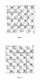
FIGURE 6 is the sketch map of the irradiative pixels of the left and the right eye arranged in alternate lines; -
FIGURE 7 is the sketch map of the irradiative pixels of the left and the right eye arranged in alternate columns; -
FIGURE 8 is the sketch map of the irradiative pixels of the left and the right eye arranged with odd parity array; -
FIGURE 9 is the sketch map of the irradiative pixels of the left and the right eye arranged with even parity array. - Next, we will give detailed description of the present invention with material implement way combined with the drawings:
- As shown in
FIGURE 1 , the present invention includes a SC electronic controller and a display screen SN. The SC electronic controller may be a scrambler, mixer or complex; the display screen SN has many display elements or display pixels. The SC electronic controller connects with the display screen SN. The SC electronic controller controls transmission and image processing. Send the image information data of the left & right eye to the display screen SN with the SC electronic controller. Then, separate the left eye image and the right eye image with a polarization system. Cover the display elements or display pixels of the display screen with polarizing film or the polarization board L or R at orthogonal angles or phases. At the SC electronic controller end, send the image information data of the left & right eye to L or R polarizing film or to the irradiative pixels shielded with the polarizing film or plate respectively, to form the left and the right eye image. When viewing, one can wear a pair of polarizing glasses with polarizing film or polarizing plate at orthogonal angles or phases to separate the left and the right eye images and enter the left eye and the right eye respectively, to form a stereoscopic image in ones brain. - The display pixel of the present invention refers to physical pixel, each display pixel includes one or two individual pixels, i.e. inserting two individual pixels at the position of each display pixel. In this way, stereoscopic display is realized, when each physical pixel can be divided into two completely individual pixels, resolution of the left eye and the right eye image may have no loss. The individual pixels in the present invention means that each pixel is 3-in-1, and can form full colour. These two individual pixels include irradiance of the left eye image, and irradiance of the right eye image. The left eye and the right eye display pixel can be arranged up and down, as shown in
FIGURE 2 ; or arranged left and right, as shown inFIGURE 3 ; or arranged separately left upward, as shown inFIGURE 4 ; or arranged separately right upward, as shown inFIGURE 5 . As shown inFIGURE 6, FIGURE 7 ,FIGURE 8 and FIGURE 9 , the display pixels or the display elements of the display screen can be divided into two sets: the irradiative pixels of the left eye and the irradiative pixels of the right eye, the irradiative pixels of the left and the right eye can be arranged line by line, column by column, in a parity array or even parity array. - The light polarizing by polarizing film may use linear polarization or circular polarization. In linear polarization mode, the polarizing angle between the left eye and the right eye is 90°, errors should be less than ±10%. In circular polarization mode, the two polarizing angles are in parallel, the two phases are orthogonal, or the polarizing angles are orthogonal, phases are in parallel, errors should be less than ±10%. For the pixel, the polarizing film may be separated, i.e. the polarizing film is set on a single irradiative pixel; or in a line, arow, i.e. shape the polarizing film into strip or belt, set on display element or display pixel in a line or arow; or make the film into block or plate covering or shielding some pixels. Hold the direction of polarizing light of the display screen SN consistent with the direction of polarizing light of the polarizing glasses PG.
- Manufacturing approach of the invention:
- Step 1, Several display elements or display pixels are set on the display screen SN. The display screen SN connects with the SC electronic controller. The SC electronic controller controls the display element or display pixel to shine;
- Step 2, Two individual pixels are inserted at each display pixel, in which one of the two individual pixels is irradiance of the left eye image, and the other is irradiance of the right eye image;
- Step 3, The polarizing film will be set on each display pixel. The polarizing film can be sticked or covered on each display pixel, fixed on each display element or display pixel other way. The screen surface can be waterproof processed for outdoor application.
- The above examples are used only for explaining the optimized implement approaches to the present invention. However, the present invention is not limited to the above mentioned implement approaches. Within knowledge field of ordinary technicians in the mentioned field, any modification within the principle of the present invention equals to substitute and improvement. Therefore, it should be under the protection of the request of the present invention.
Claims (10)
- A manufacturing approach of a large scale polarizing 3D electronic display system includes the following steps:Step1. Set a lot of display elements or display pixels on the display screen; the display elements or display pixels are controlled with a display controller;Step 2. Set two individual pixels (one is lighting for the left eye image, the other is lighting for the right eye image) at each physical display pixel area.Step 3. Set polarizing film at each display element or display pixel respectively.
- A manufacturing approach of the mentioned large scale polarizing 3D electronic display system of claim 1,with characteristics as follows: the mentioned polarizing film can be set onto the display elements or display pixels individually, line by line or column by column.
- A manufacturing approach of the mentioned large scale polarizing 3D electronic display system of claim 1, with characteristics as follows: the mentioned polarizing film can be as block or plate polarizing film for covering or shielding some pixels.
- A manufacturing approach of the mentioned large scale polarizing 3D electronic display system of claim 1, claim 2 or claim 3, with characteristics as follows: the light polarizing with the mentioned polarizing film uses linear polarization, the angle difference between left polarizing and right polarizing is 90°, errors should be less than ±10%.
- A manufacturing approach of the mentioned large scale polarizing 3D electronic display system of claim 1, claim 2 or claim 3,with characteristics as follows: the light polarizing with the mentioned polarizing film uses circular polarization, the two polarizing angles are in parallel, the two phases are orthogonal, or the polarizing angles are orthogonal, phases are in parallel, errors should be less than ±10%.
- A large scale polarizing 3D electronic display system consists of a controller and a display screen. The controller is connected with the display screen. Set a lot of display elements or display pixels on the display screen, with characteristics as follows: set the polarizing film on surface of the mentioned display elements or display pixels, each display pixel includes one or two individual pixels.
- A manufacturing approach of the mentioned large scale polarizing 3D electronic display system of claim 6, with characteristics of two individual pixels: one is lighting for the left eye image, the other is lighting for the right eye image.
- A manufacturing approach of the mentioned large scale polarizing 3D electronic display system of claim 7, with characteristics as follows: the mentioned polarizing film is set on the display elements or display pixels individually, line by line or column by column.
- A manufacturing approach of the mentioned large scale polarizing 3D electronic display system of claim 7, with characteristics as follows: the mentioned polarizing film is used as block or plate polarizing film for covering or shielding some pixels.
- A manufacturing approach of the mentioned large scale polarizing 3D electronic display system of claim 6-9(any item), with polarizing film has the following characteristics: the display elements or display pixels, of the mentioned display screen, are divided into two sets: pixels for the left eye and the pixels forthe right eye. The pixels of the left and the right eye are arranged individually, line by line, column by column, parity array or even parity array.
Applications Claiming Priority (3)
| Application Number | Priority Date | Filing Date | Title |
|---|---|---|---|
| CN2011200112066U CN201995087U (en) | 2011-01-14 | 2011-01-14 | Polarization stereo electronic large-screen display system |
| CN201110007877XA CN102098525A (en) | 2011-01-14 | 2011-01-14 | Polarized three-dimensional electronic large screen display system and manufacturing method thereof |
| PCT/CN2012/070050 WO2012094961A1 (en) | 2011-01-14 | 2012-01-05 | Polarizing stereo electronic large screen display system and manufacturing method thereof |
Publications (2)
| Publication Number | Publication Date |
|---|---|
| EP2665279A1 true EP2665279A1 (en) | 2013-11-20 |
| EP2665279A4 EP2665279A4 (en) | 2015-11-11 |
Family
ID=46506774
Family Applications (1)
| Application Number | Title | Priority Date | Filing Date |
|---|---|---|---|
| EP12734712.8A Withdrawn EP2665279A4 (en) | 2011-01-14 | 2012-01-05 | Polarizing stereo electronic large screen display system and manufacturing method thereof |
Country Status (3)
| Country | Link |
|---|---|
| US (2) | US20140085441A1 (en) |
| EP (1) | EP2665279A4 (en) |
| WO (1) | WO2012094961A1 (en) |
Families Citing this family (2)
| Publication number | Priority date | Publication date | Assignee | Title |
|---|---|---|---|---|
| CN103439824A (en) * | 2013-08-30 | 2013-12-11 | 京东方科技集团股份有限公司 | Array substrate, pixel driving method and display device |
| CN112527061B (en) * | 2020-12-07 | 2024-08-02 | 维沃移动通信有限公司 | Electronic equipment |
Family Cites Families (12)
| Publication number | Priority date | Publication date | Assignee | Title |
|---|---|---|---|---|
| US6002518A (en) * | 1990-06-11 | 1999-12-14 | Reveo, Inc. | Phase-retardation based system for stereoscopic viewing micropolarized spatially-multiplexed images substantially free of visual-channel cross-talk and asymmetric image distortion |
| US6121977A (en) * | 1996-10-18 | 2000-09-19 | Fujitsu Limited | Method and apparatus for creating image and computer memory product |
| US6084647A (en) * | 1996-11-22 | 2000-07-04 | Sharp Kabushiki Kaisha | Liquid crystal display device |
| US7372629B2 (en) * | 2003-11-06 | 2008-05-13 | Nec Corporation | Three-dimensional image display device, portable terminal device, display panel and fly eye lens |
| JP4934975B2 (en) * | 2005-03-17 | 2012-05-23 | エプソンイメージングデバイス株式会社 | Image display device |
| KR101255209B1 (en) * | 2006-05-04 | 2013-04-23 | 삼성전자주식회사 | Hihg resolution autostereoscopic display apparatus with lnterlaced image |
| CN100594737C (en) * | 2007-05-25 | 2010-03-17 | 向亚峰 | Stereoscopic image display method and system |
| JP2010072290A (en) * | 2008-09-18 | 2010-04-02 | Panasonic Corp | Stereoscopic image display |
| CN101750748B (en) * | 2008-12-04 | 2012-09-05 | 财团法人工业技术研究院 | Stereoscopic image display device |
| JP2012058265A (en) * | 2008-12-08 | 2012-03-22 | Arisawa Mfg Co Ltd | Stereoscopic image display device |
| CN201995087U (en) * | 2011-01-14 | 2011-09-28 | 郑州中原显示技术有限公司 | Polarization stereo electronic large-screen display system |
| CN102098525A (en) * | 2011-01-14 | 2011-06-15 | 郑州中原显示技术有限公司 | Polarized three-dimensional electronic large screen display system and manufacturing method thereof |
-
2012
- 2012-01-05 WO PCT/CN2012/070050 patent/WO2012094961A1/en not_active Ceased
- 2012-01-05 EP EP12734712.8A patent/EP2665279A4/en not_active Withdrawn
- 2012-01-05 US US13/979,684 patent/US20140085441A1/en not_active Abandoned
-
2017
- 2017-02-04 US US15/424,845 patent/US20170150135A1/en not_active Abandoned
Also Published As
| Publication number | Publication date |
|---|---|
| EP2665279A4 (en) | 2015-11-11 |
| US20170150135A1 (en) | 2017-05-25 |
| US20140085441A1 (en) | 2014-03-27 |
| WO2012094961A1 (en) | 2012-07-19 |
Similar Documents
| Publication | Publication Date | Title |
|---|---|---|
| US8964013B2 (en) | Display with elastic light manipulator | |
| CN102096200B (en) | Stereoscopic display device and lens array thereof | |
| US9088790B2 (en) | Display device and method of controlling the same | |
| US9213203B2 (en) | Three-dimensional image display | |
| US9104032B1 (en) | Naked-eye 3D display device and liquid crystal lens thereof | |
| CN103096109B (en) | Multiple view automatic stereoscopic displayer and display method | |
| US9188788B2 (en) | 3-dimensional displaying apparatus and method for driving 3-dimensional displaying apparatus | |
| US9438893B2 (en) | Method for setting stereoscopic image data at a stereoscopic image display system by shifting data to a vertical direction | |
| CN201917718U (en) | Novel naked-eye three-dimensional display device | |
| CN101576661B (en) | Multiple visual field stereo display | |
| CN103823308A (en) | Integrated-imaging double-vision 3D (Three-Dimensional) display device based on polarization gratings | |
| CN103472587B (en) | Stereo display device | |
| CN101364364A (en) | LED large scale freedom stereo display technique | |
| WO2015024343A1 (en) | 3d display method | |
| CN101951528B (en) | Method for reducing image crosstalk of cylindrical-surface grating stereoscopic display by adopting color filter | |
| US20170150135A1 (en) | Large scale polarizing 3d electronic display system and manufacturing approach | |
| CN212623379U (en) | 3D display device and system | |
| KR102192207B1 (en) | Image display apparatus | |
| CN102098525A (en) | Polarized three-dimensional electronic large screen display system and manufacturing method thereof | |
| CN103885193A (en) | Display device and method for displaying image thereof | |
| CN201995089U (en) | Three-dimensional large electronic screen | |
| CN201910881U (en) | Stereoscopic large screen for discrete illuminator | |
| CN203587894U (en) | Large-viewing-angle directional imaging lens array structure | |
| CN201995087U (en) | Polarization stereo electronic large-screen display system | |
| Huang et al. | Glasses-free led holoscopic 3D wall with effective pixel mapping |
Legal Events
| Date | Code | Title | Description |
|---|---|---|---|
| PUAI | Public reference made under article 153(3) epc to a published international application that has entered the european phase |
Free format text: ORIGINAL CODE: 0009012 |
|
| 17P | Request for examination filed |
Effective date: 20130814 |
|
| AK | Designated contracting states |
Kind code of ref document: A1 Designated state(s): AL AT BE BG CH CY CZ DE DK EE ES FI FR GB GR HR HU IE IS IT LI LT LU LV MC MK MT NL NO PL PT RO RS SE SI SK SM TR |
|
| RAP1 | Party data changed (applicant data changed or rights of an application transferred) |
Owner name: CENTRAL CHINA DISPLAY LABORATORIES, LTD |
|
| DAX | Request for extension of the european patent (deleted) | ||
| RA4 | Supplementary search report drawn up and despatched (corrected) |
Effective date: 20151014 |
|
| RIC1 | Information provided on ipc code assigned before grant |
Ipc: G02B 27/26 20060101ALI20151008BHEP Ipc: H04N 13/00 20060101AFI20151008BHEP |
|
| 17Q | First examination report despatched |
Effective date: 20180327 |
|
| STAA | Information on the status of an ep patent application or granted ep patent |
Free format text: STATUS: THE APPLICATION IS DEEMED TO BE WITHDRAWN |
|
| 18D | Application deemed to be withdrawn |
Effective date: 20200801 |