EP2665146A1 - Cord housing apparatus - Google Patents
Cord housing apparatus Download PDFInfo
- Publication number
- EP2665146A1 EP2665146A1 EP11855318.9A EP11855318A EP2665146A1 EP 2665146 A1 EP2665146 A1 EP 2665146A1 EP 11855318 A EP11855318 A EP 11855318A EP 2665146 A1 EP2665146 A1 EP 2665146A1
- Authority
- EP
- European Patent Office
- Prior art keywords
- cord
- power
- power reception
- ground
- charging
- Prior art date
- Legal status (The legal status is an assumption and is not a legal conclusion. Google has not performed a legal analysis and makes no representation as to the accuracy of the status listed.)
- Granted
Links
Images



Classifications
-
- H—ELECTRICITY
- H02—GENERATION; CONVERSION OR DISTRIBUTION OF ELECTRIC POWER
- H02G—INSTALLATION OF ELECTRIC CABLES OR LINES, OR OF COMBINED OPTICAL AND ELECTRIC CABLES OR LINES
- H02G11/00—Arrangements of electric cables or lines between relatively-movable parts
- H02G11/02—Arrangements of electric cables or lines between relatively-movable parts using take-up reel or drum
-
- B—PERFORMING OPERATIONS; TRANSPORTING
- B60—VEHICLES IN GENERAL
- B60L—PROPULSION OF ELECTRICALLY-PROPELLED VEHICLES; SUPPLYING ELECTRIC POWER FOR AUXILIARY EQUIPMENT OF ELECTRICALLY-PROPELLED VEHICLES; ELECTRODYNAMIC BRAKE SYSTEMS FOR VEHICLES IN GENERAL; MAGNETIC SUSPENSION OR LEVITATION FOR VEHICLES; MONITORING OPERATING VARIABLES OF ELECTRICALLY-PROPELLED VEHICLES; ELECTRIC SAFETY DEVICES FOR ELECTRICALLY-PROPELLED VEHICLES
- B60L50/00—Electric propulsion with power supplied within the vehicle
- B60L50/50—Electric propulsion with power supplied within the vehicle using propulsion power supplied by batteries or fuel cells
- B60L50/51—Electric propulsion with power supplied within the vehicle using propulsion power supplied by batteries or fuel cells characterised by AC-motors
-
- B—PERFORMING OPERATIONS; TRANSPORTING
- B60—VEHICLES IN GENERAL
- B60L—PROPULSION OF ELECTRICALLY-PROPELLED VEHICLES; SUPPLYING ELECTRIC POWER FOR AUXILIARY EQUIPMENT OF ELECTRICALLY-PROPELLED VEHICLES; ELECTRODYNAMIC BRAKE SYSTEMS FOR VEHICLES IN GENERAL; MAGNETIC SUSPENSION OR LEVITATION FOR VEHICLES; MONITORING OPERATING VARIABLES OF ELECTRICALLY-PROPELLED VEHICLES; ELECTRIC SAFETY DEVICES FOR ELECTRICALLY-PROPELLED VEHICLES
- B60L53/00—Methods of charging batteries, specially adapted for electric vehicles; Charging stations or on-board charging equipment therefor; Exchange of energy storage elements in electric vehicles
- B60L53/10—Methods of charging batteries, specially adapted for electric vehicles; Charging stations or on-board charging equipment therefor; Exchange of energy storage elements in electric vehicles characterised by the energy transfer between the charging station and the vehicle
- B60L53/14—Conductive energy transfer
-
- B—PERFORMING OPERATIONS; TRANSPORTING
- B60—VEHICLES IN GENERAL
- B60L—PROPULSION OF ELECTRICALLY-PROPELLED VEHICLES; SUPPLYING ELECTRIC POWER FOR AUXILIARY EQUIPMENT OF ELECTRICALLY-PROPELLED VEHICLES; ELECTRODYNAMIC BRAKE SYSTEMS FOR VEHICLES IN GENERAL; MAGNETIC SUSPENSION OR LEVITATION FOR VEHICLES; MONITORING OPERATING VARIABLES OF ELECTRICALLY-PROPELLED VEHICLES; ELECTRIC SAFETY DEVICES FOR ELECTRICALLY-PROPELLED VEHICLES
- B60L53/00—Methods of charging batteries, specially adapted for electric vehicles; Charging stations or on-board charging equipment therefor; Exchange of energy storage elements in electric vehicles
- B60L53/10—Methods of charging batteries, specially adapted for electric vehicles; Charging stations or on-board charging equipment therefor; Exchange of energy storage elements in electric vehicles characterised by the energy transfer between the charging station and the vehicle
- B60L53/14—Conductive energy transfer
- B60L53/18—Cables specially adapted for charging electric vehicles
-
- B—PERFORMING OPERATIONS; TRANSPORTING
- B65—CONVEYING; PACKING; STORING; HANDLING THIN OR FILAMENTARY MATERIAL
- B65H—HANDLING THIN OR FILAMENTARY MATERIAL, e.g. SHEETS, WEBS, CABLES
- B65H75/00—Storing webs, tapes, or filamentary material, e.g. on reels
- B65H75/02—Cores, formers, supports, or holders for coiled, wound, or folded material, e.g. reels, spindles, bobbins, cop tubes, cans, mandrels or chucks
- B65H75/34—Cores, formers, supports, or holders for coiled, wound, or folded material, e.g. reels, spindles, bobbins, cop tubes, cans, mandrels or chucks specially adapted or mounted for storing and repeatedly paying-out and re-storing lengths of material provided for particular purposes, e.g. anchored hoses, power cables
- B65H75/38—Cores, formers, supports, or holders for coiled, wound, or folded material, e.g. reels, spindles, bobbins, cop tubes, cans, mandrels or chucks specially adapted or mounted for storing and repeatedly paying-out and re-storing lengths of material provided for particular purposes, e.g. anchored hoses, power cables involving the use of a core or former internal to, and supporting, a stored package of material
- B65H75/40—Cores, formers, supports, or holders for coiled, wound, or folded material, e.g. reels, spindles, bobbins, cop tubes, cans, mandrels or chucks specially adapted or mounted for storing and repeatedly paying-out and re-storing lengths of material provided for particular purposes, e.g. anchored hoses, power cables involving the use of a core or former internal to, and supporting, a stored package of material mobile or transportable
- B65H75/42—Cores, formers, supports, or holders for coiled, wound, or folded material, e.g. reels, spindles, bobbins, cop tubes, cans, mandrels or chucks specially adapted or mounted for storing and repeatedly paying-out and re-storing lengths of material provided for particular purposes, e.g. anchored hoses, power cables involving the use of a core or former internal to, and supporting, a stored package of material mobile or transportable attached to, or forming part of, mobile tools, machines or vehicles
- B65H75/425—Cores, formers, supports, or holders for coiled, wound, or folded material, e.g. reels, spindles, bobbins, cop tubes, cans, mandrels or chucks specially adapted or mounted for storing and repeatedly paying-out and re-storing lengths of material provided for particular purposes, e.g. anchored hoses, power cables involving the use of a core or former internal to, and supporting, a stored package of material mobile or transportable attached to, or forming part of, mobile tools, machines or vehicles attached to, or forming part of a vehicle, e.g. truck, trailer, vessel
-
- B—PERFORMING OPERATIONS; TRANSPORTING
- B65—CONVEYING; PACKING; STORING; HANDLING THIN OR FILAMENTARY MATERIAL
- B65H—HANDLING THIN OR FILAMENTARY MATERIAL, e.g. SHEETS, WEBS, CABLES
- B65H75/00—Storing webs, tapes, or filamentary material, e.g. on reels
- B65H75/02—Cores, formers, supports, or holders for coiled, wound, or folded material, e.g. reels, spindles, bobbins, cop tubes, cans, mandrels or chucks
- B65H75/34—Cores, formers, supports, or holders for coiled, wound, or folded material, e.g. reels, spindles, bobbins, cop tubes, cans, mandrels or chucks specially adapted or mounted for storing and repeatedly paying-out and re-storing lengths of material provided for particular purposes, e.g. anchored hoses, power cables
- B65H75/38—Cores, formers, supports, or holders for coiled, wound, or folded material, e.g. reels, spindles, bobbins, cop tubes, cans, mandrels or chucks specially adapted or mounted for storing and repeatedly paying-out and re-storing lengths of material provided for particular purposes, e.g. anchored hoses, power cables involving the use of a core or former internal to, and supporting, a stored package of material
- B65H75/44—Constructional details
- B65H75/4481—Arrangements or adaptations for driving the reel or the material
- B65H75/4484—Electronic arrangements or adaptations for controlling the winding or unwinding process, e.g. with sensors
-
- B—PERFORMING OPERATIONS; TRANSPORTING
- B60—VEHICLES IN GENERAL
- B60L—PROPULSION OF ELECTRICALLY-PROPELLED VEHICLES; SUPPLYING ELECTRIC POWER FOR AUXILIARY EQUIPMENT OF ELECTRICALLY-PROPELLED VEHICLES; ELECTRODYNAMIC BRAKE SYSTEMS FOR VEHICLES IN GENERAL; MAGNETIC SUSPENSION OR LEVITATION FOR VEHICLES; MONITORING OPERATING VARIABLES OF ELECTRICALLY-PROPELLED VEHICLES; ELECTRIC SAFETY DEVICES FOR ELECTRICALLY-PROPELLED VEHICLES
- B60L2220/00—Electrical machine types; Structures or applications thereof
- B60L2220/10—Electrical machine types
- B60L2220/14—Synchronous machines
-
- B—PERFORMING OPERATIONS; TRANSPORTING
- B60—VEHICLES IN GENERAL
- B60L—PROPULSION OF ELECTRICALLY-PROPELLED VEHICLES; SUPPLYING ELECTRIC POWER FOR AUXILIARY EQUIPMENT OF ELECTRICALLY-PROPELLED VEHICLES; ELECTRODYNAMIC BRAKE SYSTEMS FOR VEHICLES IN GENERAL; MAGNETIC SUSPENSION OR LEVITATION FOR VEHICLES; MONITORING OPERATING VARIABLES OF ELECTRICALLY-PROPELLED VEHICLES; ELECTRIC SAFETY DEVICES FOR ELECTRICALLY-PROPELLED VEHICLES
- B60L2240/00—Control parameters of input or output; Target parameters
- B60L2240/80—Time limits
-
- B—PERFORMING OPERATIONS; TRANSPORTING
- B60—VEHICLES IN GENERAL
- B60L—PROPULSION OF ELECTRICALLY-PROPELLED VEHICLES; SUPPLYING ELECTRIC POWER FOR AUXILIARY EQUIPMENT OF ELECTRICALLY-PROPELLED VEHICLES; ELECTRODYNAMIC BRAKE SYSTEMS FOR VEHICLES IN GENERAL; MAGNETIC SUSPENSION OR LEVITATION FOR VEHICLES; MONITORING OPERATING VARIABLES OF ELECTRICALLY-PROPELLED VEHICLES; ELECTRIC SAFETY DEVICES FOR ELECTRICALLY-PROPELLED VEHICLES
- B60L2260/00—Operating Modes
- B60L2260/40—Control modes
- B60L2260/44—Control modes by parameter estimation
-
- B—PERFORMING OPERATIONS; TRANSPORTING
- B60—VEHICLES IN GENERAL
- B60L—PROPULSION OF ELECTRICALLY-PROPELLED VEHICLES; SUPPLYING ELECTRIC POWER FOR AUXILIARY EQUIPMENT OF ELECTRICALLY-PROPELLED VEHICLES; ELECTRODYNAMIC BRAKE SYSTEMS FOR VEHICLES IN GENERAL; MAGNETIC SUSPENSION OR LEVITATION FOR VEHICLES; MONITORING OPERATING VARIABLES OF ELECTRICALLY-PROPELLED VEHICLES; ELECTRIC SAFETY DEVICES FOR ELECTRICALLY-PROPELLED VEHICLES
- B60L50/00—Electric propulsion with power supplied within the vehicle
- B60L50/10—Electric propulsion with power supplied within the vehicle using propulsion power supplied by engine-driven generators, e.g. generators driven by combustion engines
- B60L50/16—Electric propulsion with power supplied within the vehicle using propulsion power supplied by engine-driven generators, e.g. generators driven by combustion engines with provision for separate direct mechanical propulsion
-
- B—PERFORMING OPERATIONS; TRANSPORTING
- B60—VEHICLES IN GENERAL
- B60L—PROPULSION OF ELECTRICALLY-PROPELLED VEHICLES; SUPPLYING ELECTRIC POWER FOR AUXILIARY EQUIPMENT OF ELECTRICALLY-PROPELLED VEHICLES; ELECTRODYNAMIC BRAKE SYSTEMS FOR VEHICLES IN GENERAL; MAGNETIC SUSPENSION OR LEVITATION FOR VEHICLES; MONITORING OPERATING VARIABLES OF ELECTRICALLY-PROPELLED VEHICLES; ELECTRIC SAFETY DEVICES FOR ELECTRICALLY-PROPELLED VEHICLES
- B60L50/00—Electric propulsion with power supplied within the vehicle
- B60L50/40—Electric propulsion with power supplied within the vehicle using propulsion power supplied by capacitors
-
- B—PERFORMING OPERATIONS; TRANSPORTING
- B60—VEHICLES IN GENERAL
- B60L—PROPULSION OF ELECTRICALLY-PROPELLED VEHICLES; SUPPLYING ELECTRIC POWER FOR AUXILIARY EQUIPMENT OF ELECTRICALLY-PROPELLED VEHICLES; ELECTRODYNAMIC BRAKE SYSTEMS FOR VEHICLES IN GENERAL; MAGNETIC SUSPENSION OR LEVITATION FOR VEHICLES; MONITORING OPERATING VARIABLES OF ELECTRICALLY-PROPELLED VEHICLES; ELECTRIC SAFETY DEVICES FOR ELECTRICALLY-PROPELLED VEHICLES
- B60L50/00—Electric propulsion with power supplied within the vehicle
- B60L50/50—Electric propulsion with power supplied within the vehicle using propulsion power supplied by batteries or fuel cells
- B60L50/60—Electric propulsion with power supplied within the vehicle using propulsion power supplied by batteries or fuel cells using power supplied by batteries
- B60L50/61—Electric propulsion with power supplied within the vehicle using propulsion power supplied by batteries or fuel cells using power supplied by batteries by batteries charged by engine-driven generators, e.g. series hybrid electric vehicles
-
- B—PERFORMING OPERATIONS; TRANSPORTING
- B60—VEHICLES IN GENERAL
- B60L—PROPULSION OF ELECTRICALLY-PROPELLED VEHICLES; SUPPLYING ELECTRIC POWER FOR AUXILIARY EQUIPMENT OF ELECTRICALLY-PROPELLED VEHICLES; ELECTRODYNAMIC BRAKE SYSTEMS FOR VEHICLES IN GENERAL; MAGNETIC SUSPENSION OR LEVITATION FOR VEHICLES; MONITORING OPERATING VARIABLES OF ELECTRICALLY-PROPELLED VEHICLES; ELECTRIC SAFETY DEVICES FOR ELECTRICALLY-PROPELLED VEHICLES
- B60L50/00—Electric propulsion with power supplied within the vehicle
- B60L50/50—Electric propulsion with power supplied within the vehicle using propulsion power supplied by batteries or fuel cells
- B60L50/70—Electric propulsion with power supplied within the vehicle using propulsion power supplied by batteries or fuel cells using power supplied by fuel cells
- B60L50/72—Constructional details of fuel cells specially adapted for electric vehicles
-
- B—PERFORMING OPERATIONS; TRANSPORTING
- B65—CONVEYING; PACKING; STORING; HANDLING THIN OR FILAMENTARY MATERIAL
- B65H—HANDLING THIN OR FILAMENTARY MATERIAL, e.g. SHEETS, WEBS, CABLES
- B65H2701/00—Handled material; Storage means
- B65H2701/30—Handled filamentary material
- B65H2701/34—Handled filamentary material electric cords or electric power cables
-
- Y—GENERAL TAGGING OF NEW TECHNOLOGICAL DEVELOPMENTS; GENERAL TAGGING OF CROSS-SECTIONAL TECHNOLOGIES SPANNING OVER SEVERAL SECTIONS OF THE IPC; TECHNICAL SUBJECTS COVERED BY FORMER USPC CROSS-REFERENCE ART COLLECTIONS [XRACs] AND DIGESTS
- Y02—TECHNOLOGIES OR APPLICATIONS FOR MITIGATION OR ADAPTATION AGAINST CLIMATE CHANGE
- Y02T—CLIMATE CHANGE MITIGATION TECHNOLOGIES RELATED TO TRANSPORTATION
- Y02T10/00—Road transport of goods or passengers
- Y02T10/60—Other road transportation technologies with climate change mitigation effect
- Y02T10/62—Hybrid vehicles
-
- Y—GENERAL TAGGING OF NEW TECHNOLOGICAL DEVELOPMENTS; GENERAL TAGGING OF CROSS-SECTIONAL TECHNOLOGIES SPANNING OVER SEVERAL SECTIONS OF THE IPC; TECHNICAL SUBJECTS COVERED BY FORMER USPC CROSS-REFERENCE ART COLLECTIONS [XRACs] AND DIGESTS
- Y02—TECHNOLOGIES OR APPLICATIONS FOR MITIGATION OR ADAPTATION AGAINST CLIMATE CHANGE
- Y02T—CLIMATE CHANGE MITIGATION TECHNOLOGIES RELATED TO TRANSPORTATION
- Y02T10/00—Road transport of goods or passengers
- Y02T10/60—Other road transportation technologies with climate change mitigation effect
- Y02T10/70—Energy storage systems for electromobility, e.g. batteries
-
- Y—GENERAL TAGGING OF NEW TECHNOLOGICAL DEVELOPMENTS; GENERAL TAGGING OF CROSS-SECTIONAL TECHNOLOGIES SPANNING OVER SEVERAL SECTIONS OF THE IPC; TECHNICAL SUBJECTS COVERED BY FORMER USPC CROSS-REFERENCE ART COLLECTIONS [XRACs] AND DIGESTS
- Y02—TECHNOLOGIES OR APPLICATIONS FOR MITIGATION OR ADAPTATION AGAINST CLIMATE CHANGE
- Y02T—CLIMATE CHANGE MITIGATION TECHNOLOGIES RELATED TO TRANSPORTATION
- Y02T10/00—Road transport of goods or passengers
- Y02T10/60—Other road transportation technologies with climate change mitigation effect
- Y02T10/7072—Electromobility specific charging systems or methods for batteries, ultracapacitors, supercapacitors or double-layer capacitors
-
- Y—GENERAL TAGGING OF NEW TECHNOLOGICAL DEVELOPMENTS; GENERAL TAGGING OF CROSS-SECTIONAL TECHNOLOGIES SPANNING OVER SEVERAL SECTIONS OF THE IPC; TECHNICAL SUBJECTS COVERED BY FORMER USPC CROSS-REFERENCE ART COLLECTIONS [XRACs] AND DIGESTS
- Y02—TECHNOLOGIES OR APPLICATIONS FOR MITIGATION OR ADAPTATION AGAINST CLIMATE CHANGE
- Y02T—CLIMATE CHANGE MITIGATION TECHNOLOGIES RELATED TO TRANSPORTATION
- Y02T90/00—Enabling technologies or technologies with a potential or indirect contribution to GHG emissions mitigation
- Y02T90/10—Technologies relating to charging of electric vehicles
- Y02T90/12—Electric charging stations
-
- Y—GENERAL TAGGING OF NEW TECHNOLOGICAL DEVELOPMENTS; GENERAL TAGGING OF CROSS-SECTIONAL TECHNOLOGIES SPANNING OVER SEVERAL SECTIONS OF THE IPC; TECHNICAL SUBJECTS COVERED BY FORMER USPC CROSS-REFERENCE ART COLLECTIONS [XRACs] AND DIGESTS
- Y02—TECHNOLOGIES OR APPLICATIONS FOR MITIGATION OR ADAPTATION AGAINST CLIMATE CHANGE
- Y02T—CLIMATE CHANGE MITIGATION TECHNOLOGIES RELATED TO TRANSPORTATION
- Y02T90/00—Enabling technologies or technologies with a potential or indirect contribution to GHG emissions mitigation
- Y02T90/10—Technologies relating to charging of electric vehicles
- Y02T90/14—Plug-in electric vehicles
-
- Y—GENERAL TAGGING OF NEW TECHNOLOGICAL DEVELOPMENTS; GENERAL TAGGING OF CROSS-SECTIONAL TECHNOLOGIES SPANNING OVER SEVERAL SECTIONS OF THE IPC; TECHNICAL SUBJECTS COVERED BY FORMER USPC CROSS-REFERENCE ART COLLECTIONS [XRACs] AND DIGESTS
- Y02—TECHNOLOGIES OR APPLICATIONS FOR MITIGATION OR ADAPTATION AGAINST CLIMATE CHANGE
- Y02T—CLIMATE CHANGE MITIGATION TECHNOLOGIES RELATED TO TRANSPORTATION
- Y02T90/00—Enabling technologies or technologies with a potential or indirect contribution to GHG emissions mitigation
- Y02T90/40—Application of hydrogen technology to transportation, e.g. using fuel cells
Definitions
- the present invention relates to a cord storage apparatus, and in particular, to a technique for retracting a cord away from the ground.
- a vehicle which has a power storage device for example, a secondary battery, a capacitor or the like
- a power storage device for example, a secondary battery, a capacitor or the like
- Such vehicle includes for example, an electric vehicle, a hybrid vehicle, a fuel cell vehicle and the like.
- a technique for charging the power storage device mounted in those vehicles with a commercial power supply having a high power generation efficiency has been proposed.
- hybrid vehicles some hybrid vehicles have been known as being similar to an electric vehicle, namely as having a vehicular power storage device which can be charged by a power supply external to the vehicle (hereinafter, simply referred to as “external power supply”) (this manner of charging is hereinafter referred to as “external charging”).
- a vehicular power storage device which can be charged by a power supply external to the vehicle (hereinafter, simply referred to as “external power supply”) (this manner of charging is hereinafter referred to as “external charging”).
- plug-in hybrid vehicle which is possible to have the power storage device charged from a general household power supply by connecting a power outlet disposed inside the household and a charging port disposed in the vehicle through a power reception cord. Thereby, it can be expected to improve a fuel efficiency of the hybrid vehicle.
- Japanese Patent Laying-Open No. 2003-244832 discloses an electric vehicle provided with a retractable cord for charging a battery.
- the cord contacts the ground during the time when the power storage is being charged, it is possible to have mud adhered to the cord. Therefore, a user may have to clean the cord after the end of the charging. Thereby, the contact of the cord with the ground may be inconvenient for the user.
- An object of the present invention is to reduce a dirt adhesion level of a cord.
- a cord storage apparatus includes a retracting device configured to retract a cord to be connected to a power supply, and a control unit configured to determine whether or not the cord is retracted away from the ground when the cord is connected to the power supply and control the retracting device to stop retracting the cord when the cord is retracted away from the ground.
- the cord When the cord is connected to the power supply, the cord is retracted away from the ground. Accordingly, it is possible to reduce an amount of mud or the like adhered to the cord. Thereby, it is possible to reduce a dirt adhesion level of the cord.
- Fig. 1 is an overall block diagram of a vehicle 100 mounted with a cord storage apparatus 600.
- vehicle 100 includes a power storage device 110, a SMR (System Main Relay), a PCU (Power Control Unit) 120, a motor generator 130, a power transmission gear 140, a driving wheel 150, and a vehicular ECU (Electronic Control Unit) 300.
- SMR System Main Relay
- PCU Power Control Unit
- motor generator 130 a motor generator
- power transmission gear 140 a driving wheel 150
- vehicular ECU Electric Control Unit
- Power storage device 110 is an electric power storing element configured as being chargeable and dischargeable.
- Power storage device 110 is configured to include a power storage element, for example, a secondary battery such as a lithium-ion battery, a nickel-metal hydride battery and a lead battery, or an electric double layer capacitor or the like.
- Power storage device 110 is connected to PCU 120 through a power line PL1 and a ground line NL1. Power storage device 110 supplies electric power to PCU 120 so as to generate a driving force for vehicle 100. Further, power storage device 110 stores electric power generated from motor generator 130. An output from power storage device 110 is about 200 V, for example.
- a relay disposed inside SMR is inserted respectively in power line PL1 which connects power storage device 110 to PCU 120 and ground line NL1 which connects power storage device 110 to PCU 120. Accordingly, SMR switches on or switches off the supply of power between power storage 110 and PCU 120 on the basis of a control signal SE1 from vehicular ECU 300.
- PCU 120 is configured to include a converter for boosting a power voltage supplied from power storage device 110, an inverter for converting DC power boosted by the converter into AC power for driving motor generator 130, and the like.
- the converter and inverter mentioned above are respectively controlled by control signals PWC and PWI from vehicular ECU 300.
- Motor generator 130 is an AC rotating electrical machine, for example, a permanent magnet synchronous motor equipped with a rotor having a permanent magnet buried therein.
- An output torque from motor generator 130 is transmitted to driving wheel 150 so as to drive vehicle 100 through the intermediary of power transmission gear 140 configured to include a reducer and a power split device.
- motor generator 130 may generate power from a rotating force of driving wheel 150, and the generated power is converted by PCU 120 to a charging power for charging power storage device 110.
- Fig. 1 only one motor generator is disposed; however, the number of motor generators is not limited to one, it is acceptable to dispose a plurality of motor generators.
- vehicle 100 in the present embodiment is illustrated as a vehicle mounted with an electric motor configured to generate a driving force for the vehicle, and it may include a hybrid vehicle which generates the driving force for the vehicle from an engine and an electric motor, an electric vehicle and a fuel cell vehicle without an engine, and the like.
- vehicular ECU 300 includes a CPU (Central Processing Unit), a memory device and an input/output buffer, and is configured to receive input signals from each sensor or the like, output control signals to each device, and control vehicle 100 and each device.
- CPU Central Processing Unit
- Such control of the vehicle and each device is not limited to be performed by software but also possible to be performed in dedicated hardware (electronic circuit).
- Vehicular ECU 300 is configured to generate and output control signals for controlling PCU 120, SMR and the like. In the configuration illustrated in Fig. 1 , only one vehicular ECU 300 is disposed; however, it is acceptable to dispose an individual control unit for each function or for each device to be controlled, for example, a control unit for PCU 120, a control unit for power storage device 110 and the like.
- Vehicle 100 includes an inlet 270, a charging device 200 and a relay RY2 as components for charging power storage device 110 by using electric power from an external power supply 500A.
- Inlet 270 is disposed inside a power reception port 280 disposed at an outer surface of vehicle 100.
- Power reception port 280 is incorporated with a movable lid 285 configured to cover inlet 270 when the external charging is not performed.
- a charging connector 410 of a charging cable 400 is connected to inlet 270. Thereby, the electric power from external power supply 500A is transmitted to vehicle 100 through charging cable 400.
- charging cable 400 includes a plug 420 to be connected to an outlet 510A to external power supply 500A, and a line section 430 for connecting charging connector 410 and plug 420. It is acceptable to include in line section 430 a charging-circuit blocking device (not shown) for switching on or off the supply of the electric power from external power supply 500A.
- Inlet 270 is connected to charging device 200 through power lines ACL1 and ACL2.
- a relay is also disposed at a position between inlet 270 and charging device 200.
- Vehicle 100 further includes a power reception cord 250 and a cord storage apparatus 600 as an alternative path for charging power storage device 110 by using the electric power from an external power supply 500B.
- power reception cord 250 is connected with a plug 260 to be connected to an outlet 510B to external power supply 500B.
- the other end of power reception cord 250 is connected to power lines ACL3 and ACL4 which are connected to charging device 200.
- Power lines ACL3 and ACL4 are connected to power lines ACL1 and ACL2, respectively, through the intermediary of a relay RY3.
- Relay RY3 is controlled by a control signal SE3 from vehicular ECU 300.
- Relay RY3 is configured to be electrically connected when the external charging is being performed through power reception cord 250 and disconnected when the external charging is not performed through power reception cord 250.
- power reception cord 250 When the external charging is not performed, power reception cord 250 is wound by cord storage apparatus 600 and held therein. When the external charging is performed through power reception cord 250, power reception cord 250 is pulled out from a pullout opening (not shown) of a power reception port 240 disposed at the outer surface of vehicle 100. By connecting plug 260 to outlet 510B, the electric power is transmitted from external power supply 500B to vehicle 100.
- Fig. 1 the configuration is illustrated as having charging cable 400 to be connected to outlet 510A of external power supply 500A or having power reception cord 250 to be connected to outlet 510B of external power supply 500B.
- the voltage of external power supply 500A and the voltage of external power supply 510A may be the same or may be different. In the case of different voltages, for example, charging cable 400 may be used when the voltage of the external power supply is 200 V, and power reception cord 250 may be used when the voltage of the external power supply is 100V.
- Power reception port 240 is incorporated with a movable lid 245 configured to cover the pullout opening when the external charging is not performed.
- Charging device 200 is connected to inlet 270 through power lines ACL1 and ACL2. Charging device 200 is connected to power storage device 110 through the intermediary of relay RY2 by power line PL2 and ground line NL2.
- Charging device 200 converts AC power supplied through inlet 270 or power reception cord 250 into electric power for charging power storage device 110.
- cord storage apparatus 600 includes a cord reel 610, an electric motor 620, and a control unit 650.
- Cord reel 610 is disposed with a cylindrical body configured to wind thereon power reception cord 250.
- power reception cord 250 is used to perform the external charging
- power reception cord 250 wound on cord reel 610 is pulled out. While the external charging is not performed, cord reel 610 wraps power reception cord 250 and holds it therein.
- a rotating shaft of electric motor 620 is disposed with a gear 621.
- Gear 621 is arranged in such a way that it is engageable with a gear 611 disposed on a side surface of cord reel 610.
- gear 621 is rotated by electric motor 620.
- cord reel 610 is rotated by electric motor 620 in the direction of winding power reception cord 250. Accordingly, power reception cord 250 is held in cord storage apparatus 600.
- control unit 650 controls elector motor 620 to rotate cord reel 610 in the direction of winding power reception cord 250.
- Power reception cord 250 is wound and thereby power reception cord 250 is retracted away from the ground.
- electric motor 620 functions as a device for retracting power reception cord 250. Power reception cord 250 is retracted continuously until power reception cord 250 is away from the ground.
- control unit 650 determines whether or not power reception cord 250 is retracted away from the ground when power reception cord 250 is connected to external power supply 500B, and controls electric motor 620 to stop retracting power reception cord 250 when power reception cord 250 is retracted away from the ground.
- electric motor 620 is controlled to retract power reception cord 250 at a constant torque, i.e., a constant force. It is acceptable that electric motor 620 is controlled to retract power reception cord 250 at a constant power.
- Whether or not power reception cord 250 is retracted away from the ground is determined, for example, on the basis of a rotation speed of cord reel 610 detected by a speed sensor 630.
- a tension on power reception cord 250 when power reception cord 250 is retracted away from the ground in other words, a force required to retract power reception cord 250 is greater than a tension on power reception cord 250 when power reception cord 250 is in contact with the ground. Therefore, a speed retracting power reception cord 250 when power reception cord 250 is retracted away from the ground is smaller than a speed retracting power reception cord 250 when power reception cord 250 is in contact with the ground.
- the rotation speed of cord reel 610 when power reception cord 250 is retracted away from the ground is smaller than the rotation speed of cord reel 610 when power reception cord 250 is in contact with the ground.
- the rotation speed of cord reel 610 becomes smaller than a predetermined first threshold, it is determined that power reception cord 250 is retracted away from the ground.
- electric motor 620 is controlled to retract power reception cord 250 at a constant speed.
- control unit 650 controls electric motor 620 to stop retracting power reception cord 250 when a force for retracting power reception cord 250 increases to be greater than a predetermined threshold. More specifically, as illustrated in Fig. 5 , when an output torque or an output power from electric motor 620 increases to be greater than a predetermined second threshold, it is possible to determine that power reception cord 250 is retracted away from the ground.
- the output torque or the output power of electric motor 620 is estimated or calculated on the basis of a voltage and a current or the like of electric motor 620.
- the estimation or calculation of the output torque or the output power of electric motor 620 may be performed by using generally known techniques, and therefore the descriptions thereof will not be repeated.
- control unit 650 With reference to Fig. 4 , a procedure performed by control unit 650 will be explained. In place of control unit 650, it is acceptable that the procedure to be described hereinafter is performed by a computer different from control unit 650, such as vehicular ECU 300 or the like.
- step (hereinafter, the word “step” will be abbreviated as "S") 100 whether or not a condition for starting charging power storage device 110 is satisfied is determined.
- the condition for starting charging power storage device 110 includes, for example, such a condition that a user has connected plug 260 of power reception cord 250 to external power supply 500B.
- the condition for starting charging power storage device 110 may be defined appropriately by engineers. As an example, when a voltage matching the voltage of external power supply 500B is detected by a voltage sensor disposed at a position between cord storage apparatus 600 and relay RY3, it is determined that plug 260 of power reception cord 250 is connected to external power supply 500B.
- electric motor 620 is controlled to retract power reception cord 250 at a constant torque at S102. Thereafter, if the rotation speed of cord reel 610 becomes smaller than the predetermined first threshold (YES at S104), it is determined that power reception cord 250 is retracted away from the ground. Thereby, at S108, electric motor 620 is controlled to stop retracting power reception cord 250. Accordingly, power reception cord 250 can be retracted away from the ground, as illustrated in Fig. 7 .
- power reception cord 250 is retracted away from the ground. Thereby, it is possible to reduce the amount of mud or the like adhered to power reception cord 250.
Landscapes
- Engineering & Computer Science (AREA)
- Power Engineering (AREA)
- Transportation (AREA)
- Mechanical Engineering (AREA)
- Life Sciences & Earth Sciences (AREA)
- Sustainable Development (AREA)
- Sustainable Energy (AREA)
- Electric Propulsion And Braking For Vehicles (AREA)
- Storing, Repeated Paying-Out, And Re-Storing Of Elongated Articles (AREA)
Abstract
Description
- The present invention relates to a cord storage apparatus, and in particular, to a technique for retracting a cord away from the ground.
- A vehicle which has a power storage device (for example, a secondary battery, a capacitor or the like) and travels on a driving force generated from electric power stored in the power storage device has drawn attention as an environment-friendly vehicle. Such vehicle includes for example, an electric vehicle, a hybrid vehicle, a fuel cell vehicle and the like. Moreover, there has been proposed a technique for charging the power storage device mounted in those vehicles with a commercial power supply having a high power generation efficiency.
- Among hybrid vehicles, some hybrid vehicles have been known as being similar to an electric vehicle, namely as having a vehicular power storage device which can be charged by a power supply external to the vehicle (hereinafter, simply referred to as "external power supply") (this manner of charging is hereinafter referred to as "external charging"). For example, there has been known a so-called "plug-in hybrid vehicle" which is possible to have the power storage device charged from a general household power supply by connecting a power outlet disposed inside the household and a charging port disposed in the vehicle through a power reception cord. Thereby, it can be expected to improve a fuel efficiency of the hybrid vehicle.
- After the charging is completed, the power reception cord is housed in a cord reel or the like. Japanese Patent Laying-Open No.
2003-244832 -
- PTL 1: Japanese Patent Laying-Open No.
2003-244832 - If the cord contacts the ground during the time when the power storage is being charged, it is possible to have mud adhered to the cord. Therefore, a user may have to clean the cord after the end of the charging. Thereby, the contact of the cord with the ground may be inconvenient for the user.
- An object of the present invention is to reduce a dirt adhesion level of a cord.
- A cord storage apparatus includes a retracting device configured to retract a cord to be connected to a power supply, and a control unit configured to determine whether or not the cord is retracted away from the ground when the cord is connected to the power supply and control the retracting device to stop retracting the cord when the cord is retracted away from the ground.
- When the cord is connected to the power supply, the cord is retracted away from the ground. Accordingly, it is possible to reduce an amount of mud or the like adhered to the cord. Thereby, it is possible to reduce a dirt adhesion level of the cord.
-
-
Fig. 1 is an overall block diagram of a vehicle mounted with a cord storage apparatus; -
Fig. 2 is a schematic diagram of the cord storage apparatus; -
Fig. 3 is a diagram illustrating a tension applied to a power reception cord; -
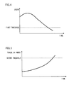
Fig. 4 is a diagram illustrating a revolution speed of a cord reel; -
Fig. 5 is a diagram illustrating an output torque or an output power from an electric motor; -
Fig. 6 is a flow chart illustrating a control process performed by a control unit; and -
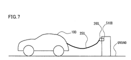
Fig. 7 is a diagram illustrating a state of the power reception cord being retracted away from the ground. - Hereinafter, an embodiment of the present invention will be described in detail with reference to the drawings. The identical or equivalent parts in the drawings will be assigned with the same reference numerals, and the description thereof will be not be repeated.
-
Fig. 1 is an overall block diagram of avehicle 100 mounted with acord storage apparatus 600. - With reference to
Fig. 1 ,vehicle 100 includes apower storage device 110, a SMR (System Main Relay), a PCU (Power Control Unit) 120, amotor generator 130, apower transmission gear 140, adriving wheel 150, and a vehicular ECU (Electronic Control Unit) 300. -
Power storage device 110 is an electric power storing element configured as being chargeable and dischargeable.Power storage device 110 is configured to include a power storage element, for example, a secondary battery such as a lithium-ion battery, a nickel-metal hydride battery and a lead battery, or an electric double layer capacitor or the like. - 14
Power storage device 110 is connected to PCU 120 through a power line PL1 and a ground line NL1.Power storage device 110 supplies electric power to PCU 120 so as to generate a driving force forvehicle 100. Further,power storage device 110 stores electric power generated frommotor generator 130. An output frompower storage device 110 is about 200 V, for example. - A relay disposed inside SMR is inserted respectively in power line PL1 which connects
power storage device 110 to PCU 120 and ground line NL1 which connectspower storage device 110 to PCU 120. Accordingly, SMR switches on or switches off the supply of power betweenpower storage 110 and PCU 120 on the basis of a control signal SE1 fromvehicular ECU 300. - Though not illustrated in any of the drawings, PCU 120 is configured to include a converter for boosting a power voltage supplied from
power storage device 110, an inverter for converting DC power boosted by the converter into AC power for drivingmotor generator 130, and the like. - The converter and inverter mentioned above are respectively controlled by control signals PWC and PWI from
vehicular ECU 300. -
Motor generator 130 is an AC rotating electrical machine, for example, a permanent magnet synchronous motor equipped with a rotor having a permanent magnet buried therein. - An output torque from
motor generator 130 is transmitted to drivingwheel 150 so as to drivevehicle 100 through the intermediary ofpower transmission gear 140 configured to include a reducer and a power split device. In a regenerative braking operation ofvehicle 100,motor generator 130 may generate power from a rotating force ofdriving wheel 150, and the generated power is converted by PCU 120 to a charging power for chargingpower storage device 110. - In the configuration illustrated in
Fig. 1 , only one motor generator is disposed; however, the number of motor generators is not limited to one, it is acceptable to dispose a plurality of motor generators. - In the case where a hybrid vehicle is mounted with an engine (not shown) in addition to
motor generator 130, required driving force is generated according to cooperative operations of the engine andmotor generator 130. In this case, it is possible to chargepower storage device 110 by using the generated power from the rotations of the engine. - In other words,
vehicle 100 in the present embodiment is illustrated as a vehicle mounted with an electric motor configured to generate a driving force for the vehicle, and it may include a hybrid vehicle which generates the driving force for the vehicle from an engine and an electric motor, an electric vehicle and a fuel cell vehicle without an engine, and the like. - Though not illustrated in
Fig. 1 , vehicular ECU 300 includes a CPU (Central Processing Unit), a memory device and an input/output buffer, and is configured to receive input signals from each sensor or the like, output control signals to each device, andcontrol vehicle 100 and each device. Such control of the vehicle and each device is not limited to be performed by software but also possible to be performed in dedicated hardware (electronic circuit). - Vehicular ECU 300 is configured to generate and output control signals for controlling PCU 120, SMR and the like. In the configuration illustrated in
Fig. 1 , only one vehicular ECU 300 is disposed; however, it is acceptable to dispose an individual control unit for each function or for each device to be controlled, for example, a control unit forPCU 120, a control unit forpower storage device 110 and the like. -
Vehicle 100 includes aninlet 270, acharging device 200 and a relay RY2 as components for chargingpower storage device 110 by using electric power from anexternal power supply 500A. - Inlet 270 is disposed inside a
power reception port 280 disposed at an outer surface ofvehicle 100.Power reception port 280 is incorporated with amovable lid 285 configured to coverinlet 270 when the external charging is not performed. - A
charging connector 410 of acharging cable 400 is connected toinlet 270. Thereby, the electric power fromexternal power supply 500A is transmitted tovehicle 100 throughcharging cable 400. - In addition to
charging connector 410,charging cable 400 includes aplug 420 to be connected to anoutlet 510A toexternal power supply 500A, and aline section 430 for connectingcharging connector 410 andplug 420. It is acceptable to include in line section 430 a charging-circuit blocking device (not shown) for switching on or off the supply of the electric power fromexternal power supply 500A. -
Inlet 270 is connected tocharging device 200 through power lines ACL1 and ACL2. A relay is also disposed at a position betweeninlet 270 andcharging device 200. -
Vehicle 100 further includes apower reception cord 250 and acord storage apparatus 600 as an alternative path for chargingpower storage device 110 by using the electric power from anexternal power supply 500B. - One end of
power reception cord 250 is connected with aplug 260 to be connected to anoutlet 510B toexternal power supply 500B. The other end ofpower reception cord 250 is connected to power lines ACL3 and ACL4 which are connected to chargingdevice 200. - Power lines ACL3 and ACL4 are connected to power lines ACL1 and ACL2, respectively, through the intermediary of a relay RY3. Relay RY3 is controlled by a control signal SE3 from
vehicular ECU 300. Relay RY3 is configured to be electrically connected when the external charging is being performed throughpower reception cord 250 and disconnected when the external charging is not performed throughpower reception cord 250. - When the external charging is not performed,
power reception cord 250 is wound bycord storage apparatus 600 and held therein. When the external charging is performed throughpower reception cord 250,power reception cord 250 is pulled out from a pullout opening (not shown) of apower reception port 240 disposed at the outer surface ofvehicle 100. By connectingplug 260 tooutlet 510B, the electric power is transmitted fromexternal power supply 500B tovehicle 100. - In
Fig. 1 , the configuration is illustrated as having chargingcable 400 to be connected tooutlet 510A ofexternal power supply 500A or havingpower reception cord 250 to be connected tooutlet 510B ofexternal power supply 500B. The voltage ofexternal power supply 500A and the voltage ofexternal power supply 510A may be the same or may be different. In the case of different voltages, for example, chargingcable 400 may be used when the voltage of the external power supply is 200 V, andpower reception cord 250 may be used when the voltage of the external power supply is 100V. -
Power reception port 240 is incorporated with amovable lid 245 configured to cover the pullout opening when the external charging is not performed. -
Charging device 200 is connected toinlet 270 through power lines ACL1 and ACL2.Charging device 200 is connected topower storage device 110 through the intermediary of relay RY2 by power line PL2 and ground line NL2. -
Charging device 200 converts AC power supplied throughinlet 270 orpower reception cord 250 into electric power for chargingpower storage device 110. - With reference to
Fig. 2 ,cord storage apparatus 600 includes acord reel 610, anelectric motor 620, and acontrol unit 650. -
Cord reel 610 is disposed with a cylindrical body configured to wind thereonpower reception cord 250. Whenpower reception cord 250 is used to perform the external charging,power reception cord 250 wound oncord reel 610 is pulled out. While the external charging is not performed,cord reel 610 wrapspower reception cord 250 and holds it therein. - A rotating shaft of
electric motor 620 is disposed with agear 621.Gear 621 is arranged in such a way that it is engageable with agear 611 disposed on a side surface ofcord reel 610. - In wrapping
power reception cord 250 oncord reel 610,gear 621 is rotated byelectric motor 620. For example, when a user presses a switch or the like,cord reel 610 is rotated byelectric motor 620 in the direction of windingpower reception cord 250. Accordingly,power reception cord 250 is held incord storage apparatus 600. - Moreover, when a user connects plug 260 of
power reception cord 250 toexternal power supply 500B to chargepower storage device 110,control unit 650 controlselector motor 620 to rotatecord reel 610 in the direction of windingpower reception cord 250.Power reception cord 250 is wound and therebypower reception cord 250 is retracted away from the ground. In other words,electric motor 620 functions as a device for retractingpower reception cord 250.Power reception cord 250 is retracted continuously untilpower reception cord 250 is away from the ground. - Specifically,
control unit 650 determines whether or notpower reception cord 250 is retracted away from the ground whenpower reception cord 250 is connected toexternal power supply 500B, and controlselectric motor 620 to stop retractingpower reception cord 250 whenpower reception cord 250 is retracted away from the ground. - In the present embodiment,
electric motor 620 is controlled to retractpower reception cord 250 at a constant torque, i.e., a constant force. It is acceptable thatelectric motor 620 is controlled to retractpower reception cord 250 at a constant power. - Whether or not
power reception cord 250 is retracted away from the ground is determined, for example, on the basis of a rotation speed ofcord reel 610 detected by aspeed sensor 630. As illustrated inFig. 3 , a tension onpower reception cord 250 whenpower reception cord 250 is retracted away from the ground, in other words, a force required to retractpower reception cord 250 is greater than a tension onpower reception cord 250 whenpower reception cord 250 is in contact with the ground. Therefore, a speed retractingpower reception cord 250 whenpower reception cord 250 is retracted away from the ground is smaller than a speed retractingpower reception cord 250 whenpower reception cord 250 is in contact with the ground. That is to say, the rotation speed ofcord reel 610 whenpower reception cord 250 is retracted away from the ground is smaller than the rotation speed ofcord reel 610 whenpower reception cord 250 is in contact with the ground. Taken into consideration the above matters, as illustrated inFig. 4 , when the rotation speed ofcord reel 610 becomes smaller than a predetermined first threshold, it is determined thatpower reception cord 250 is retracted away from the ground. - It is also acceptable that
electric motor 620 is controlled to retractpower reception cord 250 at a constant speed. In this case, it is acceptable thatcontrol unit 650 controlselectric motor 620 to stop retractingpower reception cord 250 when a force for retractingpower reception cord 250 increases to be greater than a predetermined threshold. More specifically, as illustrated inFig. 5 , when an output torque or an output power fromelectric motor 620 increases to be greater than a predetermined second threshold, it is possible to determine thatpower reception cord 250 is retracted away from the ground. - The output torque or the output power of
electric motor 620 is estimated or calculated on the basis of a voltage and a current or the like ofelectric motor 620. The estimation or calculation of the output torque or the output power ofelectric motor 620 may be performed by using generally known techniques, and therefore the descriptions thereof will not be repeated. - With reference to
Fig. 4 , a procedure performed bycontrol unit 650 will be explained. In place ofcontrol unit 650, it is acceptable that the procedure to be described hereinafter is performed by a computer different fromcontrol unit 650, such asvehicular ECU 300 or the like. - At step (hereinafter, the word "step" will be abbreviated as "S") 100, whether or not a condition for starting charging
power storage device 110 is satisfied is determined. The condition for starting chargingpower storage device 110 includes, for example, such a condition that a user has connectedplug 260 ofpower reception cord 250 toexternal power supply 500B. The condition for starting chargingpower storage device 110 may be defined appropriately by engineers. As an example, when a voltage matching the voltage ofexternal power supply 500B is detected by a voltage sensor disposed at a position betweencord storage apparatus 600 and relay RY3, it is determined thatplug 260 ofpower reception cord 250 is connected toexternal power supply 500B. - If the condition for starting charging
power storage device 110 is determined to be satisfied (YES at S100),electric motor 620 is controlled to retractpower reception cord 250 at a constant torque at S102. Thereafter, if the rotation speed ofcord reel 610 becomes smaller than the predetermined first threshold (YES at S104), it is determined thatpower reception cord 250 is retracted away from the ground. Thereby, at S108,electric motor 620 is controlled to stop retractingpower reception cord 250. Accordingly,power reception cord 250 can be retracted away from the ground, as illustrated inFig. 7 . - Referring back to
Fig. 6 , even though the rotation speed ofcord reel 610 is not smaller than the first threshold (NO at S104), if a predetermined time has elapsed after the start of retracting power reception cord 250 (YES at S106),electric motor 620 is controlled to stop retracting power reception cord 250 (S108). - After the retracting of
power reception cord 250 is stopped, the charging onpower storage device 110 is started at S110. - As mentioned above in the present embodiment,
power reception cord 250 is retracted away from the ground. Thereby, it is possible to reduce the amount of mud or the like adhered topower reception cord 250. - It should be understood that the embodiments disclosed herein have been presented for the purpose of illustration and description but not limited in all aspects. It is intended that the scope of the present invention is not limited to the description above but defined by the scope of the claims and encompasses all modifications equivalent in meaning and scope to the claims.
- 100: vehicle; 110: power storage device; 130: motor generator; 200: charging device; 240: power reception port; 245: lid; 250: power reception cord; 260: plug; 500B: external power supply; 510B: outlet; 600: cord storage apparatus; 610: cord reel; 611: gear; 620: electric motor; 621: gear; 630: speed sensor; 640: battery; 650: control unit
Claims (8)
- A cord storage apparatus comprising:a retracting device (620) configured to retract a cord (250) to be connected to a power supply (500B); anda control unit (650) configured to determine whether or not said cord (250) is retracted away from the ground when said cord (250) is connected to said power supply (500B), and control said retracting device (620) to stop retracting said cord (250) when said cord (250) is retracted away from the ground.
- The cord storage apparatus according to claim 1, wherein said control unit (650) determines that said cord (250) is retracted away from the ground when a force to retract said cord (250) is greater than a predetermined threshold.
- The cord storage apparatus according to claim 2, wherein said retracting device (620) retracts said cord (250) at a constant speed.
- The cord storage apparatus according to claim 1, wherein said control unit (650) determines that said cord (250) is retracted away from the ground when a retracting speed of said cord (250) is lower than a predetermined threshold.
- The cord storage apparatus according to claim 4, wherein said retracting device (620) retracts said cord (250) at a constant force.
- The cord storage apparatus according to claim 4, wherein said retracting device (620) retracts said cord (250) at a constant power.
- The cord storage apparatus according to claim 1, further comprising a reel (610) configured to wind said cord (250), wherein
said retracting device (620) is an electric motor configured to rotate said reel (610). - The cord storage apparatus according to claim 1, wherein said cord storage apparatus is mounted in a vehicle (100).
Applications Claiming Priority (1)
| Application Number | Priority Date | Filing Date | Title |
|---|---|---|---|
| PCT/JP2011/050308 WO2012095951A1 (en) | 2011-01-12 | 2011-01-12 | Cord housing apparatus |
Publications (3)
| Publication Number | Publication Date |
|---|---|
| EP2665146A1 true EP2665146A1 (en) | 2013-11-20 |
| EP2665146A4 EP2665146A4 (en) | 2014-08-06 |
| EP2665146B1 EP2665146B1 (en) | 2015-08-19 |
Family
ID=46506876
Family Applications (1)
| Application Number | Title | Priority Date | Filing Date |
|---|---|---|---|
| EP11855318.9A Not-in-force EP2665146B1 (en) | 2011-01-12 | 2011-01-12 | Cord housing apparatus |
Country Status (5)
| Country | Link |
|---|---|
| US (1) | US9038795B2 (en) |
| EP (1) | EP2665146B1 (en) |
| JP (1) | JP5556904B2 (en) |
| CN (1) | CN103444036B (en) |
| WO (1) | WO2012095951A1 (en) |
Cited By (1)
| Publication number | Priority date | Publication date | Assignee | Title |
|---|---|---|---|---|
| CN110356274A (en) * | 2019-06-17 | 2019-10-22 | 王仁智 | A kind of multifunction charging device based on parking stall installation |
Families Citing this family (7)
| Publication number | Priority date | Publication date | Assignee | Title |
|---|---|---|---|---|
| JP5673798B2 (en) * | 2011-03-24 | 2015-02-18 | トヨタ自動車株式会社 | Cord storage device and vehicle |
| US9461430B1 (en) | 2015-07-30 | 2016-10-04 | George Dobson | Panel with receptacles to receive different types of USB connectors |
| USD789304S1 (en) | 2015-08-28 | 2017-06-13 | George Dobson | Cord receptacle |
| US10516258B2 (en) | 2017-03-17 | 2019-12-24 | AI Incorporated | Retractable cable assembly in use with electrical devices |
| DE102017208599B4 (en) * | 2017-05-22 | 2022-02-03 | Audi Ag | Motor vehicle with a connection device |
| US10986971B1 (en) | 2018-01-09 | 2021-04-27 | Ali Ebrahimi Afrouzi | Charging station with magnetic charging contacts for mobile robotic device |
| US12059965B2 (en) | 2022-05-23 | 2024-08-13 | Beta Air, Llc | Systems and methods for an electric vehicle charger with a reel button for an electric vehicle |
Family Cites Families (22)
| Publication number | Priority date | Publication date | Assignee | Title |
|---|---|---|---|---|
| JPS5941026U (en) | 1982-09-06 | 1984-03-16 | 株式会社岡田製作所 | power supply device |
| US4692569A (en) * | 1983-04-04 | 1987-09-08 | Winner Sol N | Airline electrical ground cable feed out and retrieval storage apparatus |
| JPH0714241B2 (en) | 1986-05-20 | 1995-02-15 | 三洋電機株式会社 | Mobile work vehicle |
| JP2583544B2 (en) | 1987-12-28 | 1997-02-19 | 川崎製鉄株式会社 | Cable winding abnormality detection device for rail machine |
| JPH0241616A (en) | 1988-07-29 | 1990-02-09 | Hitachi Ltd | power supply device |
| GB9116246D0 (en) | 1991-07-27 | 1991-09-11 | Metool Prod Ltd | Cable reeling system |
| FR2686743B1 (en) * | 1992-01-27 | 1994-04-29 | Delachaux Sa | DEVICE FOR WINDING AND UNWINDING AN ENERGY TRANSPORT CABLE, OR THE LIKE. |
| JPH0779502A (en) | 1993-09-10 | 1995-03-20 | Iseki & Co Ltd | Cordill device for traveling vehicle |
| JPH07171079A (en) | 1993-12-20 | 1995-07-11 | Mitsubishi Electric Home Appliance Co Ltd | Winding device for power cord, method for preventing damage to power cord wound around the winding device, and electric device and vacuum cleaner equipped with the winding device |
| US5551545A (en) * | 1994-03-18 | 1996-09-03 | Gelfman; Stanley | Automatic deployment and retrieval tethering system |
| CN1049391C (en) * | 1995-09-18 | 2000-02-16 | 精工爱普生株式会社 | Safety mechanism for electric vehicles |
| JPH11199189A (en) | 1998-01-16 | 1999-07-27 | Toyota Autom Loom Works Ltd | Battery car |
| JP2000264547A (en) | 1999-03-16 | 2000-09-26 | Suzuki Motor Corp | Charging cord storage device for small electric vehicles |
| JP2003073099A (en) | 2001-09-05 | 2003-03-12 | Nippon Yusoki Co Ltd | Battery type fork lift |
| JP3843844B2 (en) | 2002-01-17 | 2006-11-08 | 三菱自動車工業株式会社 | Electric car |
| JP3925230B2 (en) | 2002-02-15 | 2007-06-06 | 三菱自動車工業株式会社 | Electric car |
| WO2003096505A1 (en) * | 2002-05-07 | 2003-11-20 | Royal Appliance Mfg. Co. | Auto-feed/rewind electric cord reel |
| JP3093370U (en) | 2002-10-11 | 2003-05-09 | 株式会社リンケージ | Portable charger |
| JP2005348867A (en) | 2004-06-09 | 2005-12-22 | Toyota Auto Body Co Ltd | Charge plug holder of motor-driven vehicle |
| JP5119858B2 (en) | 2007-10-26 | 2013-01-16 | トヨタ自動車株式会社 | Charging port structure for vehicles |
| CN201332253Y (en) * | 2009-01-04 | 2009-10-21 | 何军 | Integral charging telescopic winding apparatus for electric bicycle |
| DE102009016895A1 (en) * | 2009-04-08 | 2010-10-14 | Illinois Tool Works Inc., Glenview | Charging terminal device for an electrically driven motor vehicle |
-
2011
- 2011-01-12 CN CN201180062494.0A patent/CN103444036B/en not_active Expired - Fee Related
- 2011-01-12 WO PCT/JP2011/050308 patent/WO2012095951A1/en not_active Ceased
- 2011-01-12 JP JP2012552554A patent/JP5556904B2/en active Active
- 2011-01-12 US US13/879,483 patent/US9038795B2/en not_active Expired - Fee Related
- 2011-01-12 EP EP11855318.9A patent/EP2665146B1/en not_active Not-in-force
Cited By (1)
| Publication number | Priority date | Publication date | Assignee | Title |
|---|---|---|---|---|
| CN110356274A (en) * | 2019-06-17 | 2019-10-22 | 王仁智 | A kind of multifunction charging device based on parking stall installation |
Also Published As
| Publication number | Publication date |
|---|---|
| US20130277484A1 (en) | 2013-10-24 |
| CN103444036A (en) | 2013-12-11 |
| WO2012095951A1 (en) | 2012-07-19 |
| EP2665146A4 (en) | 2014-08-06 |
| US9038795B2 (en) | 2015-05-26 |
| CN103444036B (en) | 2016-03-16 |
| JPWO2012095951A1 (en) | 2014-06-09 |
| EP2665146B1 (en) | 2015-08-19 |
| JP5556904B2 (en) | 2014-07-23 |
Similar Documents
| Publication | Publication Date | Title |
|---|---|---|
| EP2665146B1 (en) | Cord housing apparatus | |
| EP2521236B1 (en) | Wire housing device, vehicle equipped with the same, and power feeding device | |
| CN102448766B (en) | Charging system | |
| CN103370838B (en) | Adapter, vehicle equipped with adapter, and vehicle control method | |
| CN102510816B (en) | Vehicle and vehicle control method | |
| CN103348551B (en) | Vehicle boarded cable and vehicle | |
| EP3068658B1 (en) | Charging and discharging system and vehicle used therein | |
| EP2735467B1 (en) | Vehicle | |
| JP5672378B2 (en) | Power supply system, vehicle equipped with the same, and control method of power supply system | |
| CN103782465A (en) | Accommodation device for charging cable, and vehicle | |
| JP2011087408A (en) | Power supply system of vehicle | |
| US10252621B2 (en) | Power source device for vehicle | |
| JP2012249384A (en) | Vehicle | |
| JP2012065480A (en) | Wire storage device and vehicle loading the same | |
| US20160257296A1 (en) | Controller for hybrid vehicle | |
| WO2013042244A1 (en) | Vehicle power supply system | |
| JP5989589B2 (en) | Electrical system | |
| WO2012164681A1 (en) | Vehicle and method for controlling vehicle | |
| JP5884802B2 (en) | Control device for hybrid vehicle | |
| WO2012059989A1 (en) | Cord housing device, and vehicle installed with cord housing device | |
| JP5994718B2 (en) | Vehicle and power supply system | |
| WO2012060008A1 (en) | Electric wire storage device and vehicle mounted with the same | |
| JP2014187771A (en) | Vehicle | |
| WO2012090261A1 (en) | Recharging system, vehicle, and recharging method | |
| JP2014060824A (en) | Charging and discharging system |
Legal Events
| Date | Code | Title | Description |
|---|---|---|---|
| PUAI | Public reference made under article 153(3) epc to a published international application that has entered the european phase |
Free format text: ORIGINAL CODE: 0009012 |
|
| 17P | Request for examination filed |
Effective date: 20130520 |
|
| AK | Designated contracting states |
Kind code of ref document: A1 Designated state(s): AL AT BE BG CH CY CZ DE DK EE ES FI FR GB GR HR HU IE IS IT LI LT LU LV MC MK MT NL NO PL PT RO RS SE SI SK SM TR |
|
| DAX | Request for extension of the european patent (deleted) | ||
| A4 | Supplementary search report drawn up and despatched |
Effective date: 20140704 |
|
| RIC1 | Information provided on ipc code assigned before grant |
Ipc: H02G 11/02 20060101AFI20140630BHEP Ipc: B60L 11/18 20060101ALI20140630BHEP Ipc: H02J 7/00 20060101ALI20140630BHEP Ipc: B65H 75/42 20060101ALI20140630BHEP Ipc: B65H 75/44 20060101ALI20140630BHEP |
|
| RIC1 | Information provided on ipc code assigned before grant |
Ipc: B60L 11/18 20060101ALI20150219BHEP Ipc: H02J 7/00 20060101ALI20150219BHEP Ipc: B60L 11/12 20060101ALI20150219BHEP Ipc: B65H 75/44 20060101ALI20150219BHEP Ipc: B65H 75/42 20060101ALI20150219BHEP Ipc: H02G 11/02 20060101AFI20150219BHEP Ipc: B60L 11/00 20060101ALI20150219BHEP Ipc: B60L 11/14 20060101ALI20150219BHEP |
|
| GRAP | Despatch of communication of intention to grant a patent |
Free format text: ORIGINAL CODE: EPIDOSNIGR1 |
|
| INTG | Intention to grant announced |
Effective date: 20150331 |
|
| GRAS | Grant fee paid |
Free format text: ORIGINAL CODE: EPIDOSNIGR3 |
|
| GRAA | (expected) grant |
Free format text: ORIGINAL CODE: 0009210 |
|
| AK | Designated contracting states |
Kind code of ref document: B1 Designated state(s): AL AT BE BG CH CY CZ DE DK EE ES FI FR GB GR HR HU IE IS IT LI LT LU LV MC MK MT NL NO PL PT RO RS SE SI SK SM TR |
|
| REG | Reference to a national code |
Ref country code: GB Ref legal event code: FG4D |
|
| REG | Reference to a national code |
Ref country code: CH Ref legal event code: EP |
|
| REG | Reference to a national code |
Ref country code: IE Ref legal event code: FG4D |
|
| REG | Reference to a national code |
Ref country code: AT Ref legal event code: REF Ref document number: 744389 Country of ref document: AT Kind code of ref document: T Effective date: 20150915 |
|
| REG | Reference to a national code |
Ref country code: DE Ref legal event code: R096 Ref document number: 602011019040 Country of ref document: DE |
|
| REG | Reference to a national code |
Ref country code: DE Ref legal event code: R082 Ref document number: 602011019040 Country of ref document: DE Representative=s name: TBK, DE |
|
| REG | Reference to a national code |
Ref country code: DE Ref legal event code: R084 Ref document number: 602011019040 Country of ref document: DE |
|
| REG | Reference to a national code |
Ref country code: AT Ref legal event code: MK05 Ref document number: 744389 Country of ref document: AT Kind code of ref document: T Effective date: 20150819 |
|
| REG | Reference to a national code |
Ref country code: LT Ref legal event code: MG4D |
|
| REG | Reference to a national code |
Ref country code: NL Ref legal event code: MP Effective date: 20150819 |
|
| PG25 | Lapsed in a contracting state [announced via postgrant information from national office to epo] |
Ref country code: LT Free format text: LAPSE BECAUSE OF FAILURE TO SUBMIT A TRANSLATION OF THE DESCRIPTION OR TO PAY THE FEE WITHIN THE PRESCRIBED TIME-LIMIT Effective date: 20150819 Ref country code: FI Free format text: LAPSE BECAUSE OF FAILURE TO SUBMIT A TRANSLATION OF THE DESCRIPTION OR TO PAY THE FEE WITHIN THE PRESCRIBED TIME-LIMIT Effective date: 20150819 Ref country code: NO Free format text: LAPSE BECAUSE OF FAILURE TO SUBMIT A TRANSLATION OF THE DESCRIPTION OR TO PAY THE FEE WITHIN THE PRESCRIBED TIME-LIMIT Effective date: 20151119 Ref country code: GR Free format text: LAPSE BECAUSE OF FAILURE TO SUBMIT A TRANSLATION OF THE DESCRIPTION OR TO PAY THE FEE WITHIN THE PRESCRIBED TIME-LIMIT Effective date: 20151120 Ref country code: LV Free format text: LAPSE BECAUSE OF FAILURE TO SUBMIT A TRANSLATION OF THE DESCRIPTION OR TO PAY THE FEE WITHIN THE PRESCRIBED TIME-LIMIT Effective date: 20150819 |
|
| PG25 | Lapsed in a contracting state [announced via postgrant information from national office to epo] |
Ref country code: RS Free format text: LAPSE BECAUSE OF FAILURE TO SUBMIT A TRANSLATION OF THE DESCRIPTION OR TO PAY THE FEE WITHIN THE PRESCRIBED TIME-LIMIT Effective date: 20150819 Ref country code: ES Free format text: LAPSE BECAUSE OF FAILURE TO SUBMIT A TRANSLATION OF THE DESCRIPTION OR TO PAY THE FEE WITHIN THE PRESCRIBED TIME-LIMIT Effective date: 20150819 Ref country code: AT Free format text: LAPSE BECAUSE OF FAILURE TO SUBMIT A TRANSLATION OF THE DESCRIPTION OR TO PAY THE FEE WITHIN THE PRESCRIBED TIME-LIMIT Effective date: 20150819 Ref country code: SE Free format text: LAPSE BECAUSE OF FAILURE TO SUBMIT A TRANSLATION OF THE DESCRIPTION OR TO PAY THE FEE WITHIN THE PRESCRIBED TIME-LIMIT Effective date: 20150819 Ref country code: PT Free format text: LAPSE BECAUSE OF FAILURE TO SUBMIT A TRANSLATION OF THE DESCRIPTION OR TO PAY THE FEE WITHIN THE PRESCRIBED TIME-LIMIT Effective date: 20151221 Ref country code: PL Free format text: LAPSE BECAUSE OF FAILURE TO SUBMIT A TRANSLATION OF THE DESCRIPTION OR TO PAY THE FEE WITHIN THE PRESCRIBED TIME-LIMIT Effective date: 20150819 Ref country code: IS Free format text: LAPSE BECAUSE OF FAILURE TO SUBMIT A TRANSLATION OF THE DESCRIPTION OR TO PAY THE FEE WITHIN THE PRESCRIBED TIME-LIMIT Effective date: 20151219 |
|
| PG25 | Lapsed in a contracting state [announced via postgrant information from national office to epo] |
Ref country code: NL Free format text: LAPSE BECAUSE OF FAILURE TO SUBMIT A TRANSLATION OF THE DESCRIPTION OR TO PAY THE FEE WITHIN THE PRESCRIBED TIME-LIMIT Effective date: 20150819 |
|
| PG25 | Lapsed in a contracting state [announced via postgrant information from national office to epo] |
Ref country code: IT Free format text: LAPSE BECAUSE OF FAILURE TO SUBMIT A TRANSLATION OF THE DESCRIPTION OR TO PAY THE FEE WITHIN THE PRESCRIBED TIME-LIMIT Effective date: 20150819 Ref country code: CZ Free format text: LAPSE BECAUSE OF FAILURE TO SUBMIT A TRANSLATION OF THE DESCRIPTION OR TO PAY THE FEE WITHIN THE PRESCRIBED TIME-LIMIT Effective date: 20150819 Ref country code: EE Free format text: LAPSE BECAUSE OF FAILURE TO SUBMIT A TRANSLATION OF THE DESCRIPTION OR TO PAY THE FEE WITHIN THE PRESCRIBED TIME-LIMIT Effective date: 20150819 Ref country code: DK Free format text: LAPSE BECAUSE OF FAILURE TO SUBMIT A TRANSLATION OF THE DESCRIPTION OR TO PAY THE FEE WITHIN THE PRESCRIBED TIME-LIMIT Effective date: 20150819 Ref country code: SK Free format text: LAPSE BECAUSE OF FAILURE TO SUBMIT A TRANSLATION OF THE DESCRIPTION OR TO PAY THE FEE WITHIN THE PRESCRIBED TIME-LIMIT Effective date: 20150819 |
|
| REG | Reference to a national code |
Ref country code: DE Ref legal event code: R097 Ref document number: 602011019040 Country of ref document: DE |
|
| PG25 | Lapsed in a contracting state [announced via postgrant information from national office to epo] |
Ref country code: BE Free format text: LAPSE BECAUSE OF NON-PAYMENT OF DUE FEES Effective date: 20160131 Ref country code: RO Free format text: LAPSE BECAUSE OF FAILURE TO SUBMIT A TRANSLATION OF THE DESCRIPTION OR TO PAY THE FEE WITHIN THE PRESCRIBED TIME-LIMIT Effective date: 20150819 |
|
| PLBE | No opposition filed within time limit |
Free format text: ORIGINAL CODE: 0009261 |
|
| STAA | Information on the status of an ep patent application or granted ep patent |
Free format text: STATUS: NO OPPOSITION FILED WITHIN TIME LIMIT |
|
| 26N | No opposition filed |
Effective date: 20160520 |
|
| PG25 | Lapsed in a contracting state [announced via postgrant information from national office to epo] |
Ref country code: SI Free format text: LAPSE BECAUSE OF FAILURE TO SUBMIT A TRANSLATION OF THE DESCRIPTION OR TO PAY THE FEE WITHIN THE PRESCRIBED TIME-LIMIT Effective date: 20150819 Ref country code: LU Free format text: LAPSE BECAUSE OF FAILURE TO SUBMIT A TRANSLATION OF THE DESCRIPTION OR TO PAY THE FEE WITHIN THE PRESCRIBED TIME-LIMIT Effective date: 20160112 |
|
| REG | Reference to a national code |
Ref country code: CH Ref legal event code: PL |
|
| GBPC | Gb: european patent ceased through non-payment of renewal fee |
Effective date: 20160112 |
|
| PG25 | Lapsed in a contracting state [announced via postgrant information from national office to epo] |
Ref country code: MC Free format text: LAPSE BECAUSE OF FAILURE TO SUBMIT A TRANSLATION OF THE DESCRIPTION OR TO PAY THE FEE WITHIN THE PRESCRIBED TIME-LIMIT Effective date: 20150819 |
|
| REG | Reference to a national code |
Ref country code: FR Ref legal event code: ST Effective date: 20160930 |
|
| PG25 | Lapsed in a contracting state [announced via postgrant information from national office to epo] |
Ref country code: CH Free format text: LAPSE BECAUSE OF NON-PAYMENT OF DUE FEES Effective date: 20160131 Ref country code: LI Free format text: LAPSE BECAUSE OF NON-PAYMENT OF DUE FEES Effective date: 20160131 Ref country code: GB Free format text: LAPSE BECAUSE OF NON-PAYMENT OF DUE FEES Effective date: 20160112 |
|
| REG | Reference to a national code |
Ref country code: IE Ref legal event code: MM4A |
|
| PG25 | Lapsed in a contracting state [announced via postgrant information from national office to epo] |
Ref country code: FR Free format text: LAPSE BECAUSE OF NON-PAYMENT OF DUE FEES Effective date: 20160201 |
|
| PG25 | Lapsed in a contracting state [announced via postgrant information from national office to epo] |
Ref country code: BE Free format text: LAPSE BECAUSE OF FAILURE TO SUBMIT A TRANSLATION OF THE DESCRIPTION OR TO PAY THE FEE WITHIN THE PRESCRIBED TIME-LIMIT Effective date: 20150819 |
|
| PG25 | Lapsed in a contracting state [announced via postgrant information from national office to epo] |
Ref country code: IE Free format text: LAPSE BECAUSE OF NON-PAYMENT OF DUE FEES Effective date: 20160112 |
|
| PG25 | Lapsed in a contracting state [announced via postgrant information from national office to epo] |
Ref country code: MT Free format text: LAPSE BECAUSE OF FAILURE TO SUBMIT A TRANSLATION OF THE DESCRIPTION OR TO PAY THE FEE WITHIN THE PRESCRIBED TIME-LIMIT Effective date: 20150819 |
|
| PG25 | Lapsed in a contracting state [announced via postgrant information from national office to epo] |
Ref country code: CY Free format text: LAPSE BECAUSE OF FAILURE TO SUBMIT A TRANSLATION OF THE DESCRIPTION OR TO PAY THE FEE WITHIN THE PRESCRIBED TIME-LIMIT Effective date: 20150819 Ref country code: SM Free format text: LAPSE BECAUSE OF FAILURE TO SUBMIT A TRANSLATION OF THE DESCRIPTION OR TO PAY THE FEE WITHIN THE PRESCRIBED TIME-LIMIT Effective date: 20150819 Ref country code: HU Free format text: LAPSE BECAUSE OF FAILURE TO SUBMIT A TRANSLATION OF THE DESCRIPTION OR TO PAY THE FEE WITHIN THE PRESCRIBED TIME-LIMIT; INVALID AB INITIO Effective date: 20110112 |
|
| PG25 | Lapsed in a contracting state [announced via postgrant information from national office to epo] |
Ref country code: HR Free format text: LAPSE BECAUSE OF FAILURE TO SUBMIT A TRANSLATION OF THE DESCRIPTION OR TO PAY THE FEE WITHIN THE PRESCRIBED TIME-LIMIT Effective date: 20150819 Ref country code: MK Free format text: LAPSE BECAUSE OF FAILURE TO SUBMIT A TRANSLATION OF THE DESCRIPTION OR TO PAY THE FEE WITHIN THE PRESCRIBED TIME-LIMIT Effective date: 20150819 Ref country code: MT Free format text: LAPSE BECAUSE OF FAILURE TO SUBMIT A TRANSLATION OF THE DESCRIPTION OR TO PAY THE FEE WITHIN THE PRESCRIBED TIME-LIMIT Effective date: 20160131 Ref country code: TR Free format text: LAPSE BECAUSE OF FAILURE TO SUBMIT A TRANSLATION OF THE DESCRIPTION OR TO PAY THE FEE WITHIN THE PRESCRIBED TIME-LIMIT Effective date: 20150819 |
|
| PG25 | Lapsed in a contracting state [announced via postgrant information from national office to epo] |
Ref country code: BG Free format text: LAPSE BECAUSE OF FAILURE TO SUBMIT A TRANSLATION OF THE DESCRIPTION OR TO PAY THE FEE WITHIN THE PRESCRIBED TIME-LIMIT Effective date: 20150819 |
|
| PG25 | Lapsed in a contracting state [announced via postgrant information from national office to epo] |
Ref country code: AL Free format text: LAPSE BECAUSE OF FAILURE TO SUBMIT A TRANSLATION OF THE DESCRIPTION OR TO PAY THE FEE WITHIN THE PRESCRIBED TIME-LIMIT Effective date: 20150819 |
|
| PGFP | Annual fee paid to national office [announced via postgrant information from national office to epo] |
Ref country code: DE Payment date: 20211130 Year of fee payment: 12 |
|
| REG | Reference to a national code |
Ref country code: DE Ref legal event code: R119 Ref document number: 602011019040 Country of ref document: DE |
|
| PG25 | Lapsed in a contracting state [announced via postgrant information from national office to epo] |
Ref country code: DE Free format text: LAPSE BECAUSE OF NON-PAYMENT OF DUE FEES Effective date: 20230801 |