EP2665061B1 - Signal processing device, method and program - Google Patents
Signal processing device, method and program Download PDFInfo
- Publication number
- EP2665061B1 EP2665061B1 EP12734067.7A EP12734067A EP2665061B1 EP 2665061 B1 EP2665061 B1 EP 2665061B1 EP 12734067 A EP12734067 A EP 12734067A EP 2665061 B1 EP2665061 B1 EP 2665061B1
- Authority
- EP
- European Patent Office
- Prior art keywords
- sine wave
- information
- signal
- high frequency
- noise
- Prior art date
- Legal status (The legal status is an assumption and is not a legal conclusion. Google has not performed a legal analysis and makes no representation as to the accuracy of the status listed.)
- Active
Links
- 238000012545 processing Methods 0.000 title claims description 144
- 238000000034 method Methods 0.000 title claims description 8
- 230000005236 sound signal Effects 0.000 claims description 86
- 238000001514 detection method Methods 0.000 claims description 30
- 238000003672 processing method Methods 0.000 claims 1
- 230000007274 generation of a signal involved in cell-cell signaling Effects 0.000 description 30
- 238000010586 diagram Methods 0.000 description 15
- 238000005516 engineering process Methods 0.000 description 8
- 239000000284 extract Substances 0.000 description 3
- 230000005540 biological transmission Effects 0.000 description 2
- 238000004364 calculation method Methods 0.000 description 2
- 238000004891 communication Methods 0.000 description 2
- 230000003247 decreasing effect Effects 0.000 description 2
- 230000003287 optical effect Effects 0.000 description 2
- 238000005070 sampling Methods 0.000 description 2
- 239000004065 semiconductor Substances 0.000 description 2
- 230000002123 temporal effect Effects 0.000 description 2
- 238000012546 transfer Methods 0.000 description 2
- 230000003044 adaptive effect Effects 0.000 description 1
- 230000015572 biosynthetic process Effects 0.000 description 1
- 230000015556 catabolic process Effects 0.000 description 1
- 238000006243 chemical reaction Methods 0.000 description 1
- 238000006731 degradation reaction Methods 0.000 description 1
- 230000001419 dependent effect Effects 0.000 description 1
- 230000000694 effects Effects 0.000 description 1
- 230000005284 excitation Effects 0.000 description 1
- 230000006870 function Effects 0.000 description 1
- 230000010354 integration Effects 0.000 description 1
- 238000012986 modification Methods 0.000 description 1
- 230000004048 modification Effects 0.000 description 1
- 230000008447 perception Effects 0.000 description 1
- 238000013139 quantization Methods 0.000 description 1
- 230000010076 replication Effects 0.000 description 1
- 230000035807 sensation Effects 0.000 description 1
- 230000003595 spectral effect Effects 0.000 description 1
- 238000003786 synthesis reaction Methods 0.000 description 1
- 238000013519 translation Methods 0.000 description 1
Images


Classifications
-
- G—PHYSICS
- G10—MUSICAL INSTRUMENTS; ACOUSTICS
- G10L—SPEECH ANALYSIS OR SYNTHESIS; SPEECH RECOGNITION; SPEECH OR VOICE PROCESSING; SPEECH OR AUDIO CODING OR DECODING
- G10L19/00—Speech or audio signals analysis-synthesis techniques for redundancy reduction, e.g. in vocoders; Coding or decoding of speech or audio signals, using source filter models or psychoacoustic analysis
- G10L19/008—Multichannel audio signal coding or decoding using interchannel correlation to reduce redundancy, e.g. joint-stereo, intensity-coding or matrixing
-
- G—PHYSICS
- G10—MUSICAL INSTRUMENTS; ACOUSTICS
- G10L—SPEECH ANALYSIS OR SYNTHESIS; SPEECH RECOGNITION; SPEECH OR VOICE PROCESSING; SPEECH OR AUDIO CODING OR DECODING
- G10L21/00—Processing of the speech or voice signal to produce another audible or non-audible signal, e.g. visual or tactile, in order to modify its quality or its intelligibility
- G10L21/04—Time compression or expansion
-
- G—PHYSICS
- G10—MUSICAL INSTRUMENTS; ACOUSTICS
- G10L—SPEECH ANALYSIS OR SYNTHESIS; SPEECH RECOGNITION; SPEECH OR VOICE PROCESSING; SPEECH OR AUDIO CODING OR DECODING
- G10L19/00—Speech or audio signals analysis-synthesis techniques for redundancy reduction, e.g. in vocoders; Coding or decoding of speech or audio signals, using source filter models or psychoacoustic analysis
- G10L19/02—Speech or audio signals analysis-synthesis techniques for redundancy reduction, e.g. in vocoders; Coding or decoding of speech or audio signals, using source filter models or psychoacoustic analysis using spectral analysis, e.g. transform vocoders or subband vocoders
- G10L19/0204—Speech or audio signals analysis-synthesis techniques for redundancy reduction, e.g. in vocoders; Coding or decoding of speech or audio signals, using source filter models or psychoacoustic analysis using spectral analysis, e.g. transform vocoders or subband vocoders using subband decomposition
- G10L19/0208—Subband vocoders
-
- G—PHYSICS
- G10—MUSICAL INSTRUMENTS; ACOUSTICS
- G10L—SPEECH ANALYSIS OR SYNTHESIS; SPEECH RECOGNITION; SPEECH OR VOICE PROCESSING; SPEECH OR AUDIO CODING OR DECODING
- G10L19/00—Speech or audio signals analysis-synthesis techniques for redundancy reduction, e.g. in vocoders; Coding or decoding of speech or audio signals, using source filter models or psychoacoustic analysis
- G10L19/02—Speech or audio signals analysis-synthesis techniques for redundancy reduction, e.g. in vocoders; Coding or decoding of speech or audio signals, using source filter models or psychoacoustic analysis using spectral analysis, e.g. transform vocoders or subband vocoders
- G10L19/028—Noise substitution, i.e. substituting non-tonal spectral components by noisy source
-
- G—PHYSICS
- G10—MUSICAL INSTRUMENTS; ACOUSTICS
- G10L—SPEECH ANALYSIS OR SYNTHESIS; SPEECH RECOGNITION; SPEECH OR VOICE PROCESSING; SPEECH OR AUDIO CODING OR DECODING
- G10L19/00—Speech or audio signals analysis-synthesis techniques for redundancy reduction, e.g. in vocoders; Coding or decoding of speech or audio signals, using source filter models or psychoacoustic analysis
- G10L19/04—Speech or audio signals analysis-synthesis techniques for redundancy reduction, e.g. in vocoders; Coding or decoding of speech or audio signals, using source filter models or psychoacoustic analysis using predictive techniques
- G10L19/08—Determination or coding of the excitation function; Determination or coding of the long-term prediction parameters
- G10L19/093—Determination or coding of the excitation function; Determination or coding of the long-term prediction parameters using sinusoidal excitation models
-
- G—PHYSICS
- G10—MUSICAL INSTRUMENTS; ACOUSTICS
- G10L—SPEECH ANALYSIS OR SYNTHESIS; SPEECH RECOGNITION; SPEECH OR VOICE PROCESSING; SPEECH OR AUDIO CODING OR DECODING
- G10L21/00—Processing of the speech or voice signal to produce another audible or non-audible signal, e.g. visual or tactile, in order to modify its quality or its intelligibility
- G10L21/02—Speech enhancement, e.g. noise reduction or echo cancellation
- G10L21/038—Speech enhancement, e.g. noise reduction or echo cancellation using band spreading techniques
-
- H—ELECTRICITY
- H03—ELECTRONIC CIRCUITRY
- H03M—CODING; DECODING; CODE CONVERSION IN GENERAL
- H03M7/00—Conversion of a code where information is represented by a given sequence or number of digits to a code where the same, similar or subset of information is represented by a different sequence or number of digits
- H03M7/30—Compression; Expansion; Suppression of unnecessary data, e.g. redundancy reduction
- H03M7/40—Conversion to or from variable length codes, e.g. Shannon-Fano code, Huffman code, Morse code
Definitions
- the present invention relates to a signal processing device, method, and program, and particularly, relates to a signal processing device, program, and method that enables audio to be obtained at a higher audio quality in a case of decoding encoding audio signals.
- audio signal encoding methods such as HE-AAC (High Efficiency MPEG (Moving Picture Experts Group) 4 AAC (Advanced Audio Coding)) (international standard ISO/IEC 14496-3) are known.
- HE-AAC High Efficiency MPEG (Moving Picture Experts Group) 4 AAC (Advanced Audio Coding)
- SBR Spectrum Band Replication
- SBR when encoding audio signals, SBR information is output for generating high frequency components of the audio signal (hereafter, referred to as high frequency signal) together with low frequency components of the encoded audio signal (hereafter, low frequency signal).
- high frequency signal the audio signal
- low frequency signal the encoded audio signal
- This kind of SBR information includes envelope information mainly representing an envelope form for the high frequency components, and noise envelope information representing for obtaining a noise signal added during the generation of the high frequency components at the decoding device.
- the noise envelope information includes information representing a boundary position for dividing each SBR frame of the noise signal included in the high frequency components into two zones (hereafter, referred to as the noise boundary position), and information representing gain of noise signals in each zone. Therefore, at the decoding device, a gain adjustment is performed on each zone divided by the noise boundary position on a predetermined noise signal on the basis of the noise envelope information to establish a final noise signal. Further, with SBR, it is also possible to set the gain on the entire SBR frame without dividing the SBR frame of the noise signal into two zones.
- the decoding device When decoding the audio signal, the decoding device generates the high frequency components by combining a pseudo high frequency signal obtained from the low frequency signal and the envelope information, and the noise signal obtained from the noise envelope information, and generates the audio signal from the obtained high frequency components and the low frequency signal.
- an encoding using sine wave synthesis is performed on an audio signal with a high tone characteristic. That is to say, when generating the high frequency components at the decoding side, a sine wave signal of a particular frequency is added to the pseudo high frequency signal in addition to the noise signal. In this case, the signal obtained from combining the pseudo high frequency signal, the noise signal, and the sine wave signal is set to the high frequency signal obtained as a prediction.
- a sine wave information representing the existence/non-existence of the sine wave signal in the SBR frame is included in the SBR information.
- the combination start position of the sine wave signal used during decoding is either the start position of the SBR frame or the noise boundary position
- the sine wave information is made up of binary information representing the existence/non-existence of a sine wave signal combination in each zone of the SBR frame divided by the noise boundary position.
- the noise signal and the sine wave signal added to the pseudo high frequency signal are components that are difficult to reproduce from the envelope information within the high frequency components of the source audio signal. Therefore, by combining the noise signal and the sine wave signal at a suitable position in the pseudo high frequency signal, it is possible to predict the high frequency components with higher accuracy, and it is possible to reproduce audio at a higher audio quality by performing band pass expansion using the high frequency components obtained by prediction.
- US 2005/0080621 A1 relates to a decoding apparatus and decoding method for an audio bandwidth expansion system for generating a wideband audio signal from a narrowband audio signal by adding additional information containing little information, and relates to technology enabling this system to provide high audio quality playback with few calculations
- the combination start position of the sine wave signal is set as the SBR frame start position or the noise boundary position, which may cause variance in the emergence start position of the sine wave components in the original audio signal, in some cases.
- the combination start position of the sine wave signal is set as the SBR frame start position or the noise boundary position, which may cause variance in the emergence start position of the sine wave components in the original audio signal, in some cases.
- the frame length is fixed and not dependent on the sampling rate of the audio signal to be encoded, and so when the sampling rate is low, the absolute time length for one frame becomes longer. For this reason, the amount of variance (difference) in absolute time between the emergence start position of the sine wave components in the source audio signal and the combination start position of the sine wave signal to be combined during decoding increases, and quantization noise becomes noticeable at these zones of variance.
- the present technology has been made taking this kind of situation into consideration to enable the obtainment of audio at a higher audio quality when decoding audio signals.
- audio may be obtained at a higher audio quality when decoding an audio signal.
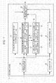
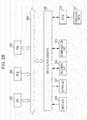
- Fig. 1 is a diagram illustrating a configuration example of a first Embodiment of an encoding device applying the present technology.
- An encoding device 11 is configured with a downsampler 21, a low frequency encoding unit 22, a band pass division filter 23, an envelope information generating unit 24, a noise envelope information generating unit 25, a sine wave information generating unit 26, and an encoding stream generating unit 27.
- the encoding device 11 encodes and outputs an input audio signal, and the audio signal input into the encoding device 11 is supplied to the downsampler 21 and the band pass division filter 23.
- the downsampler 21 extracts the low frequency signal, which is the low frequency components of the audio signal, by downsampling the input audio signal, and supplies this to the low frequency encoding unit 22 and the noise envelope information generating unit 25. Further, hereafter, the frequency band components at or below a certain frequency of the audio signal are referred to as the low frequency components, and the frequency band components higher than the low frequency components of the audio signal are referred to as the high frequency components.
- the low frequency encoding unit 22 encodes the low frequency signal supplied from the downsampler 21, and supplies this to the encoding stream generating unit 27.
- the band pass division filter 23 conducts a filter processing on the input audio signal, and performs a band pass division of the audio signal. As a result of this band pass division, the audio signal is divided into a signal of multiple band components. Further, hereafter, each band signal configuring the high frequency components from within each band signal obtained by the band pass division is referred to as the high frequency signal.
- the band pass division filter 23 supplies the high frequency signal from the high frequency side of each band obtained by the band pass division to the envelope information generating unit 24, the noise envelope information generating unit 25, and the sine wave information generating unit 26.
- the envelope information generating unit 24 generates an envelope information representing a form of an envelope (envelope) for the high frequency signal of the band for each band on the high frequency side on the basis of the high frequency signal supplied from the band pass division filter 23, and then supplies this to the noise envelope information generating unit 25. Also, the envelope information generating unit 24 is provisioned with an encoding unit 41, and the encoding unit 41 encodes the envelope information generated by the envelope information generating unit 24, and supplies this to the encoding stream generating unit 27.
- the noise envelope information generating unit 25 generates a noise envelope information while receiving information from the sine wave information generating unit 26 as necessary, on the basis of the high frequency signal from the band pass division filter 23 and the envelope information from the envelope information generating unit 24.
- the noise envelope information is information made up from information representing a boundary position (noise boundary position) for dividing the noise signal included in the high frequency components of the audio signal, and information representing the noise signal gain for each zone divided at the noise boundary position. Further, the noise signal is a previously determined signal.
- the noise envelope information generating unit 25 is provisioned with a signal generating unit 51, a boundary calculating unit 52, and an encoding unit 53.
- the signal generating unit 51 predicts the high frequency side of the audio signal for each band component on the basis of the low frequency signal from the downsampler 21 and the envelope information from the envelope information generating unit 24.
- the boundary calculating unit 52 determines the noise boundary position used for dividing the noise signal into multiple zones on the basis of the noise signal envelope obtained from the high frequency signal and a pseudo high frequency signal, which is the result of the high frequency side of each band pass component predicted during the generation of the noise envelope information.
- the encoding unit 53 encodes the noise envelope information generated by the noise envelope information generating unit 25, and supplies this to the encoding stream generating unit 27.
- the sine wave information generating unit 26 generates sine wave information used for obtaining the sine wave signal included in the band for each band at the high frequency side while receiving the information from the noise envelope information generating unit 25 as necessary, on the basis of the high frequency signal supplied from the band pass division filter 23.
- the sine wave information is information made up from information representing the existence/non-existence of a sine wave signal included in the high frequency components of the audio signal, and information used for identifying the emergence start position of the sine wave signal. That is to say, the sine wave information may be information made up from information representing the existence/non-existence of a sine wave signal to be combined with the pseudo high frequency components during decoding of the audio signal, and information representing the combination start position of the sine wave signal.
- sine wave information generating unit 26 is provisioned with a sine wave detection unit 61, a position detection unit 62, and an encoding unit 63.
- the sine wave detection unit 61 detects the existence/non-existence of the sine wave components from the high frequency signal during generation of the sine wave information.
- the position detection unit 62 detects the combination start position indicating where the combination of the sine wave signal should start, that is to say, the emergence start position of the sine wave signal, on the basis of the high frequency signal from the band pass division filter 23.
- the encoding unit 63 encodes the sine wave information generated by the sine wave information generating unit 26, and supplies this to the encoding stream generating unit 27.
- the encoding stream generating unit 27 encodes the low frequency signal from the low frequency encoding unit 22, the envelope information from the envelope information generating unit 24, the noise envelope information from the noise envelope information generating unit 25, and the sine wave information from the sine wave information generating unit 26, and outputs the encoding stream obtained from this encoding. That is to say, the low frequency signal, the envelope information, the noise envelope information, and the sine wave information are multiplexed into the encoding stream.
- the encoding device 11 When the audio signal is input into the encoding device 11, and instructed to encode the audio signal, the encoding device 11 performs the encoding processing to perform the encoding of the audio signal, and outputs the encoding stream obtained as the result.
- the encoding processing by the encoding device 11 will be described with reference to the flowchart in Fig. 2 .
- the downsampler 21 downsamples the input audio signal to generate the low frequency signal, and supplies this to the noise envelope information generating unit 25 and the low frequency encoding unit 22.
- the low frequency encoding unit 22 encodes the low frequency signal supplied from the downsampler 21, and supplies this to the encoding stream generating unit 27.
- the low frequency signal is encoded by an encoding method such as MPEG4 AAC, MPEG2 AAC, CELP (Code Exited Linear Prediction), TCX (Transform Coded Excitation), or AMR (Adaptive Multi-Rate).
- the band pass division filter 23 divides the input audio signal into bands, and the high frequency components obtained as the result are supplied to the envelope information generating unit 24 through the sine wave information generating unit 26.
- high frequency signals may be obtained as high frequency components from 64 different bands.
- the envelope information generating unit 24 generates the envelope information for each band on the basis of the high frequency signal for each band supplied from the band pass division filter 23.
- the envelope information generating unit 24 may designate a zone made up of 32 samples of the high frequency signal as one frame, and generate the envelope information for each band per frame.
- the envelope information generating unit 24 obtains an average sample value of two samples of the high frequency signal neighboring on a time line in one frame, and this average value becomes the new high frequency signal sample value.
- the high frequency signal for one frame is converted from a 32-sample signal to a 16-sample signal.
- the envelope information generating unit 24 performs a difference encoding on the high frequency signal that is now 16 samples, and the information obtained as the result becomes the envelope information. For example, the difference between the sample value of two high frequency signal samples to be processed neighboring on a time line is obtained by the difference encoding, and this difference becomes the envelope information. Also, the envelope information may be made up of the difference between the sample value of a sample of the high frequency signal of the band to be processed and the sample value of a sample in a band adjacent to that band, in the same position as the high frequency signal band, for example.
- the envelope information obtained in this way is the information representing the form of the envelope for one frame of the high frequency signal.
- the encoding unit 41 performs a variable length encoding such as Huffman encoding on the generated envelope information, and supplies the encoded envelope information to the encoding stream generating unit 27. Also, the envelope information generating unit 24 supplies the envelope information to the noise envelope information generating unit 25.
- the high frequency signal will continue to be described as that processed in units of one frame configured of 32 samples. Also, hereafter, the zone configured from two samples of the high frequency signal (audio signal) will be called one timeslot.
- the signal generating unit 51 in the noise envelope information generating unit 25 generates the pseudo high frequency signal for each band at the high frequency side on the basis of the envelope information supplied from the envelope information generating unit 24 and the low frequency signal supplied from the downsampler 21.
- the signal generating unit 51 extracts the zone for one frame of a predetermined band of the low frequency signal, and manipulates the extracted low frequency signal into the envelope form represented by the envelope information. That is to say, the sample value of the sample of the low frequency signal is increased or decreased so that the position gain corresponding to the sample fits in the envelope represented by the envelope information, and the signal obtained as the result becomes the pseudo high frequency signal.
- the pseudo high frequency signal obtained in this way has the almost the same envelope form as the envelope of the actual high frequency signal represented by the envelope information. That is to say, the pseudo high frequency signal is generated from the low frequency signal and the envelope information.
- the noise envelope information generating unit 25 extracts the difference between the high frequency signal and the pseudo high frequency signal for each band at the high frequency side, and obtains the envelope for the noise signal (hereafter, referred to as the noise envelope).
- the noise envelope obtained at step S16 is a virtual noise envelope.
- the receiving side of the encoding stream output from the encoding device 11 predicts the high frequency components of the audio signal during the decoding of the audio signal, but this prediction is performed by combining of the pseudo high frequency signal, the noise signal, and the sine wave signal.
- the high frequency components of the actual audio signal are assumed to include the pseudo high frequency signal, the noise signal, and the sine wave signal.
- the difference between the high frequency signal and the pseudo high frequency signal is obtained, and this difference should be the combination of the noise signal and the sine wave signal.
- the difference obtained in this way is considered as the envelope of the noise signal including the sine wave signal.
- the noise envelope information generating unit 25 supplies the virtual noise envelope for each band at the high frequency side obtained as previously described to the sine wave information generating unit 26.
- the sine wave detection unit 61 in the sine wave information generating unit 26 detects the sine wave components from the high frequency signal for each band on the basis of the virtual noise envelope supplied from the noise envelope information generating unit 25.
- the sine wave detection unit 61 conducts a frequency conversion on the virtual noise envelope, and converts the noise envelope into frequency components. Then, when there are frequency spikes having high power in the obtained frequency components, the sine wave detection unit 61 recognizes these frequency components as the sine wave components. Specifically, when the difference between the power of the frequency under observation and the power of other surrounding frequencies is at or above a predetermined threshold, the frequency under observation is recognized as the sine wave component. The sine wave signal for the frequency detected in this way is determined as the sine wave signal included in the actual high frequency components.
- the position detection unit 62 in the sine wave information generating unit 26 detects, for each band, the combination start position where the sine wave signal, which is the detected sine wave component, should be combined on the basis of the high frequency signal supplied from the band pass division filter 23.
- the position detection unit 62 obtains the difference between the average sample value of the samples included in one timeslot of the high frequency signal, in units of timeslots, and the average sample value of samples included in one timeslot of the detected sine wave signal. Then, the position detection unit 62 determines the combination start position looking from the beginning of the zone for one frame as the final position (start position of the timeslot or the final position of the sample) where the value of the obtained difference is at or above a predetermined threshold.
- This combination start position is the emergence start position of the sine wave signal included in the actual high frequency signals, from a timing after the combination start position, the difference in the average sample values of the high frequency signal and the sine wave signal should decrease.
- the sine wave information generating unit 26 supplies the information representing whether or not the sine wave has been detected from the bands, the information representing the frequency and power of the detected sine wave signal, and the combination start position to the noise envelope information generating unit 25.
- the sine wave information generating unit 26 generates the sine wave information for each band at the high frequency side, and supplies this to the encoding stream generating unit 27.
- the sine wave information generating unit 26 designates the information made up from the information representing whether or not the sine wave signal has been detected from the high frequency band and the combination start position as the sine wave information. Also, during the generation of the sine wave information, the encoding unit 63 in the sine wave information generating unit 26 performs the variable length encoding of the information representing the combination start position.
- the information representing whether or not the sine wave signal has been detected is, more specifically, information representing which frequency in the high frequency band is the sine wave component.
- the information used for identifying the frequencies of these sine wave signals is designated as the information representing whether or not the sine wave signals were detected.
- information representing the combination start position is generated for each sine wave signal.
- the sine wave information made up only of information representing whether or not the sine wave signal has been detected is transmitted to the decoding side. That is to say, the sine wave information not including information representing the combination start position is transmitted.
- the encoding device 11 may select whether or not to transmit the sine wave information to the decoding side per frame. In this way, by enabling the transmission of the sine wave information to be selectable, transfer efficiency of the encoding stream in increased, and at the same time, a resetting of the time information of the sine wave components may be performed. As a result, when starting the decoding processing from an arbitrary frame within the stream on the decoding side of the encoding stream, the sine wave component from the frame including the information representing the combination start position may be started.
- the combination start position on the decoding side has conventionally been either the start position of the frame or the noise boundary position.
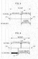
- the horizontal axis in the figure represents the time line.
- an arrow FS1 and an arrow FE1 in Fig. 3 represent the start position and end position of the frame, respectively.
- the position represented by an arrow N1 is the noise boundary position
- the combination start position of the sine wave signal is also in the same position as the noise boundary position. Therefore, the sine wave signal is combined in a zone from the position represented by the arrow N1 until the end position of the frame.
- the combination start position output to the decoding side is not limited to being the same as the noise boundary position.
- the horizontal axis in the figure represents the time line.
- an arrow FS2 and arrow FE2 in Fig. 4 represent the start position and the end position of the frame, respectively.
- the position represented by an arrow N2 represents the noise boundary position.
- the combination start position of the sine wave signal is the position represented by an arrow G1, and this combination start position is before the noise boundary position.
- the sine wave signal is combined in the zone from the combination start position represented by the arrow G1 until the end position of the frame.
- the information representing the length of time (time distance) from the start position of the frame represented by the arrow FS2 until the combination start position represented by the arrow G1 is designated as the information representing the combination start position.
- the time from the beginning of the frame until the combination start position is an integral multiple of the timeslot length.
- the sine wave information has been previously described as information generated representing the combination start position for the high frequency side for each band, but the sine wave information may use a representative value of the combination start positions for these bands shared for each band configuring the high frequency. In such a case, for example, the information representing the combination start position for the band out of multiple bands configuring the high frequency which has the sine wave signal of the highest power becomes the sine wave information.
- the information representing the combination start position has been described above as the sine wave information to which variable length encoding has been performed, but the information representing the combination start position may not be encoded.
- step S19 the sine wave information is generated, and afterwards, processing proceeds to a step S20.
- the boundary calculating unit 52 in the noise envelope information generating unit 25 detects the noise boundary position for each band at the high frequency side.
- the boundary calculating unit 52 generates the sine wave information included in the frame for the band configuring the high frequency on the basis of the information representing whether or not the sine wave signal has been detected, the information representing the frequency and power of the sine wave signal, and the combination start position. For example, when the sine wave signal is detected, the zone from the beginning of the frame until the combination start position is designated as a silent zone, and the zone from this point is made up of the sine wave component of a predetermined amplitude of the detected frequency. At this time, the amplitude of the sine wave signal is determined from the information representing the power of the sine wave signal supplied from the sine wave information generating unit 26. Also, when the sine wave signal is not detected, the amplitude of the sine wave signal is set to zero.
- the boundary calculating unit 52 subtracts the sine wave signal obtained in this way from the virtual noise envelope obtained at a step S16 to obtain the final noise envelope. Then, the boundary calculating unit 52 determines the noise boundary position according to the distribution of the final noise envelope gain.
- the boundary calculating unit 52 divides the frame into two zones as necessary based on the distribution of the gain of the final noise envelope. Specifically, when the noise envelope gain is nearly the same value for the entire frame of the band being processed, the division of the frame is not performed. That is to say, there is no noise boundary position.
- the noise boundary position is designated as the timeslot boundary position.
- the noise envelope information generating unit 25 generates the noise envelope information for each band at the high frequency side, and supplies this to the encoding stream generating unit 27.
- the noise envelope information generating unit 25 designates the noise envelope information as the information made up from the noise boundary position, and the noise signal gain in each zone in the frame divided by this noise boundary position.
- the encoding unit 53 performs an encoding of the information representing the noise boundary position, and a variable length encoding of the information representing the gain for each divided zone.
- the gain for each divided zone is the average gain value of the noise envelope in these zones, for example. That is to say, the frame being processed is divided into two zones by the noise boundary position. In this case, the gain for the zone from the beginning of the frame until the noise boundary position is the average gain value for each position of the final noise envelope in this zone.
- the encoding stream generating unit 27 encodes the low frequency signal from the low frequency encoding unit 22, the envelope information from the envelope information generating unit 24, the noise envelope information from the noise envelope information generating unit 25, and the sine wave information from the sine wave information generating unit 26, and generates the encoding stream. Then, the encoding stream generating unit 27 transmits the encoding stream obtained from the encoding to the decoding device, etc., and the encoding processing terminates.
- the encoding device 11 generates and outputs the encoding stream made up from the low frequency signal, the envelope information, the noise envelope information, and the sine wave information.
- the encoding device 11 generates and outputs the encoding stream made up from the low frequency signal, the envelope information, the noise envelope information, and the sine wave information.
- a more accurate combination start position of the sine wave signal being detected, and generating the sine wave information including this combination start position a more accurate sine wave signal combination may be performed at the decoding side of the audio signal, which results in the obtainment of audio at a higher audio quality.
- the low frequency signal generated by the downsampler 21 has been described above to be supplied to the noise envelope information generating unit 25, but the low frequency signal supplied to the noise envelope information generating unit 25 may be a low frequency signal obtained by division of the bands by the band pass division filter 23. Also, the low frequency signal encoded by the low frequency encoding unit 22 is obtained by decoding, but this may also be supplied to the noise envelope information generating unit 25.
- a decoding device which receives the encoding stream output from the encoding device 11 in Fig. 1 , and obtains the audio signal from the encoding stream will be described.
- This kind of decoding device is configured as illustrated in Fig. 5 , for example.
- a decoding device 91 in Fig. 5 is configured with an encoding stream decoding unit 101, a low frequency decoding unit 102, an envelope information decoding unit 103, a noise envelope information decoding unit 104, a sine wave information decoding unit 105, and a band pass combination filter 106.
- the encoding stream decoding unit 101 receives and decodes the encoding stream transmitted from the encoding device 11. That is to say, the encoding stream decoding unit 101 inverse multiplexes the encoding stream, and the low frequency signal, the envelope information, the noise envelope information, and the sine wave information obtained as a result is supplied to the low frequency decoding unit 102, the envelope information decoding unit 103, the noise envelope information decoding unit 104, and the sine wave information decoding unit 105, respectively.
- the low frequency decoding unit 102 decodes the low frequency signal supplied from the encoding stream decoding unit 101, and supplies this to the envelope information decoding unit 103 and the band pass combination filter 106.
- the envelope information decoding unit 103 decodes the envelope information supplied from the encoding stream decoding unit 101, and also supplies the decoded envelope information to the sine wave information decoding unit 105. Also, the envelope information decoding unit 103 is provisioned with a generating unit 121, and the generating unit 121 generates envelop information and the pseudo high frequency signal based on the low frequency signal from the low frequency decoding unit 102, and supplies this to the band pass combination filter 106.
- the noise envelope information decoding unit 104 decodes the noise envelope information supplied from the encoding stream decoding unit 101. Also, the noise envelope information decoding unit 104 is provisioned with a generating unit 131, and the generating unit 131 generates the noise signal based on the noise envelope information, and supplies this to the band pass combination filter 106.
- the sine wave information decoding unit 105 decodes the sine wave information supplied from the encoding stream decoding unit 101. Also, the sine wave information decoding unit 105 is provisioned with a generating unit 141, and the generating unit 141 generates the sine wave signal based on the sine wave information and envelope information from the envelope information decoding unit 103, and supplies this to the band pass combination filter 106.
- the band pass combination filter 106 combines the bands of the low frequency signal from the low frequency decoding unit 102, the pseudo high frequency signal from the envelope information decoding unit 103, the noise signal from the noise envelope information decoding unit 104, and the sine wave signal from the sine wave information decoding unit 105 to generate the audio signal.
- the band pass combination filter 106 outputs the signal obtained from combining the bands as the decoded audio signal to a downstream player unit or similar.
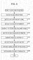
- the decoding device 91 When the encoding stream from the encoding device 11 is transmitted to the decoding device 91 illustrated in Fig. 5 , the decoding device 91 performs the decoding processing in units of frames to decode the audio signal. Hereafter, the decoding processing performed by the decoding device 91 will be described with reference to Fig. 6 .
- the encoding stream decoding unit 101 decodes the encoding stream received from the encoding device 11, and supplies the low frequency signal, envelope information, noise envelope information, and sine wave information obtained as a result to the low frequency decoding unit 102 through the sine wave information decoding unit 105.
- the low frequency decoding unit 102 decoded the low frequency signal from the encoding stream decoding unit 101, and supplies this to the envelope information decoding unit 103 and the band pass combination filter 106.
- the envelope information decoding unit 103 decodes the envelope information from the encoding stream decoding unit 101. Also, the envelope information decoding unit 103 supplies the decoded envelope information to the sine wave information decoding unit 105.
- the generating unit 121 in the envelope information decoding unit 103 generates the pseudo high frequency signal for each band at the high frequency side, on the basis of the low frequency signal from the low frequency decoding unit 102, and supplies this to the band pass combination filter 106.
- the generating unit 121 generates the pseudo high frequency signal by extracting the zone for one frame regarding a predetermined band of the low frequency signal, and increasing or decreasing the low frequency signal so that the sample value of the extracted low frequency signal sample matches the gain of the position in the envelope represented by the envelope information corresponding to this sample.
- the noise envelope information decoding unit 104 decodes the noise envelope information from the encoding stream decoding unit 101.
- the generating unit 131 in the noise envelope information decoding unit 104 generates the noise signal for each band at the high frequency side, on the basis of the noise envelope information, and supplies this to the band pass combination filter 106. That is to say, the generating unit 131 generates the noise signal by adjusting the gain for each zone of a predetermined signal which has been divided into zones by the noise boundary position represented by the noise envelope information so that the gain of this signal matches the gain represented by the noise envelope information.
- the sine wave information decoding unit 105 decodes the sine wave information from the encoding stream decoding unit 101. For example, the information representing the combination start position included in the sine wave information is decoded as necessary.
- the sine wave information decoding unit 105 performs the sine wave signal generation processing to generate the sine wave signal for each band at the high frequency side, and supplies this to the band pass combination filter 106. Further, the details of the sine wave signal generation processing will be described later.
- the band pass combination filter 106 combines the bands of the low frequency signal from the low frequency decoding unit 102, the pseudo high frequency signal from the envelope information decoding unit 103, the noise signal from the noise envelope information decoding unit 104, and the sine wave signal from the sine wave information decoding unit 105.
- the audio signal is generated by performing the band combination by adding the samples at each timing from the low frequency signal, the pseudo high frequency signal for each band, the noise signal for each band, and the sine wave signal for each band input from the low frequency decoding unit 102 through the sine wave information decoding unit 105.
- the signal made up of the pseudo high frequency signal, the noise signal, and the sine wave signal is the high frequency component obtained by prediction.
- the band pass combination filter 106 When the audio signal has been obtained by the band combination, the band pass combination filter 106 outputs this audio signal to a downstream player unit or similar, and the decoding processing terminates. This decoding processing is performed per frame, and as the next frame of the encoding stream is input, the decoding device 91 performs the decoding processing on this frame of the encoding stream.
- the decoding device 91 predicts the high frequency components on the basis of the low frequency signal, the envelope information, the noise envelope information, and the sine wave information, and generates the audio signal by expanding the bands from the high frequency signal obtained by prediction and the decoded low frequency signal.
- the sine wave information representing a more accurate combination start position of the sine wave signal, a more accurate sine wave signal combination may be performed, and so audio at a higher audio quality may be obtained.
- the generating unit 141 in the sine wave information decoding unit 105 determines whether or not the start timing for the sine wave signal combination processing has passed based on the combination start position and the information included in the sine wave information representing whether or not the sine wave signal has been detected.
- the generating unit 141 generates the sine wave signal as the sine wave component configuring the high frequency component by designating the beginning of the frame as the emergence start position and the end of the frame as the emergence end position.
- the frequency of the sine wave signal designated as the sine wave component configuring the high frequency component is identified by the information included in the sine wave information representing whether or not the sine wave signal has been detected.
- the amplitude of the sine wave signal frequency identified by the sine wave information is identified from the envelope information supplied from the envelope information decoding unit 103 through the sine wave information decoding unit 105.
- the generating unit 141 converts the envelope information into frequencies, and obtains the amplitude of the sine wave signal based on the power of the sine wave signal frequency from among the power of all frequencies obtained as a result.
- the generating unit 141 selects the sample in the start position of the timeslot for one frame of the sine wave signal as the sample (timeslot) to be processed in order from the beginning of the frame. Then, the generating unit 141 determines whether or not the selected sample position is the sample position represented by the combination start position, that is to say the timing at which the combination of the sine wave signal should be started. For example, when information included in the sine wave information indicates that the sine wave signal has not been detected, this will continue to be determined that the start timing of the sine wave combination processing has not passed.
- the generating unit 141 shifts the generated sine wave signal backward on a timeline by one timeslot. As a result, the emergence start position of the sine wave signal is shifted backward on a timeline.
- the shifting of the sine wave signal is performed, the sine wave has not yet emerged in the timeslot zone to be processed, and so the sine wave signal is not output from the sine wave information decoding unit 105 to the band pass combination filter 106.
- the generating unit 141 determines whether or not the end of one frame has been reached. For example, when the zone for the final timeslot configuring the frame is being processed, that is to say, when all timeslots in the frame have been processed, this is determined that the end of the frame has been reached.
- the next timeslot is selected as that to be processed, the processing returns to step S81, and the previously described processing repeats.
- the shit processing, etc. is performed on the sine wave signal already generated.
- the sine wave signal generation processing terminates, and afterwards, the processing proceeds to a step S59 in Fig. 6 .
- the result is that the sine wave signal combination is not performed.
- the generating unit 141 performs the sine wave combination processing. That is to say, the generating unit 141 outputs to the band pass combination filter 106 the sample value configuring the timeslot being processed of the sine wave signal which has been arbitrarily shift processed. As a result, the sample value of the output sine wave signal sample is combined with the low frequency signal as the sine wave component configuring the high frequency component.
- the generating unit 141 determines whether or not the end of one frame has been reached. For example, when the zone for the final timeslot configuring the frame is being processed, that is to say, when all timeslots in the frame have been processed, this is determined that the end of the frame has been reached.
- step S85 When it has been determined that the end of the frame has not been reached at the step S85, the next timeslot is selected as that to be processed, the processing returns to step S84, and the previously described processing repeats. Conversely, when it has been determined that the end of the frame has been reached at the step S85, the sine wave signal generation processing terminates, and afterwards, the processing proceeds to the step S59 in Fig. 6 .
- the sine wave information decoding unit 105 shifts the emergence start position of the sine wave signal to the combination start position on the basis of the sine wave information, and outputs the shifted sine wave signal.
- the combination of the sine wave is started at a more accurate position in one frame, and so audio at a higher audio quality may be obtained.
- the combination start position representing the time (number of samples) from the beginning position of the frame until the position at which the combination of the sine wave signal should start is included in the sine wave information
- information of the difference between the combination start position and the noise boundary position may be included.
- the encoding device is configured as illustrated in Fig. 8 .
- the components in Fig. 8 that correspond to those in Fig. 1 have the same reference numerals, and so their descriptions will be omitted as appropriate.
- An encoding device 171 in Fig. 8 and the encoding device 11 are different in that a difference calculating unit 181 is newly provisioned in the sine wave information generating unit 26 of the encoding device 171, and so are the same regarding other components.
- the difference calculating unit 181 in the sine wave information generating unit 26 calculates the difference between the combination start position of the sine wave signal detected by the position detection unit 62 and the noise boundary position.
- the sine wave information generating unit 26 supplies information made up from the difference information representing the difference with the noise boundary position calculated by the difference calculating unit 181 and the information representing whether or not the sine wave signal has been detected to the encoding stream generating unit 27 as the sine wave information.
- step S111 through the step S118 are the same as the step S11 through the step S18 in Fig. 2 , and so their description is omitted.
- the boundary calculating unit 52 in the noise envelope information generating unit 25 detects the noise boundary position for each band at the high frequency side. Then, at a step S20, the noise envelope information generating unit 25 generates the noise envelope information for each band at the high frequency side, and supplies this to the encoding stream generating unit 27. Further, at the step S119 and step S120, the same processing as at step S20 and step S21 in Fig. 2 is performed.
- the difference calculating unit 181 in the sine wave information generating unit 26 calculates the difference between the noise boundary position and the combination start position of the sine wave signal detected by the position detection unit 62.
- the time (number of samples) from the start position of the sine wave combination until the noise boundary position is calculated as the difference.
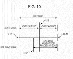
- the horizontal axis in the figure represents the timeline.
- an arrow FS11 and an arrow FE11 in Fig. 10 represent the start position and the end position of the frame, respectively.
- the position represented by an arrow N11 in the frame represents the noise boundary position.
- the combination start position of the sine wave signal is the position represented by an arrow G11, and the combination start position is positioned before the noise boundary position. Therefore, the sine wave signal is combined in the zone from the combination start position represented by the arrow G11 until the end position of the frame.
- the length of time (temporal distance) from the combination start position represented by the arrow G11 until the noise boundary position represented by the arrow N11 is designated as the difference information with the noise boundary position.
- the time from the combination start position until the noise boundary position is an integral multiple of the timeslot length.
- the sine wave information generating unit 26 generates the sine wave information for each band at the high frequency side, and supplies this to the encoding stream generating unit 27.
- the sine wave information generating unit 26 designates the information made up from the information representing whether or not the sine wave has been detected from the high frequency band and the difference information between the combination start position and the noise boundary position as the sine wave information.
- the encoding unit 63 in the sine wave information generating unit 26 performs the variable length encoding of the difference information with the noise boundary position.
- the sine wave information generating unit 26 supplies the sine wave information made up from the difference information processed by the variable length encoding and the information representing whether or not the sine wave signal has been detected to the encoding stream generating unit 27.
- the processing at a step S123 is performed and the encoding processing terminates, and as the processing at the step S123 is the same as the processing at the step S22 in Fig. 2 , so its description is omitted.
- the encoding device 171 generates and outputs the encoding stream made up from the low frequency signal, the envelope information, the noise envelope information, and the sine wave information. At this time, by detecting a more accurate combination start position of the sine wave signal and generating sine wave information including the difference information used for identifying this combination start position, a more accurate combination of the sine wave signal may be performed during decoding, and so audio at a higher audio quality may be obtained as a result.
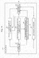
- a decoding device that receives the encoding stream transmitted from the encoding device 171, and obtains the audio signal from the encoding stream is configured as illustrated in Fig. 11 .
- the components in Fig. 11 that correspond to those in Fig. 5 have the same reference numerals, and so their descriptions will be omitted as appropriate.
- a decoding device 211 in Fig. 11 and the decoding device 91 are different in that a position calculating unit 221 is newly provisioned in the sine wave information decoding unit 105 of the decoding device 211, and so are the same regarding other components.
- the position calculating unit 221 in the decoding device 211 calculates the combination start position of the sine wave signal from the difference information obtained from the sine wave information and the noise boundary position supplied from the noise envelope information decoding unit 104.
- the decoding processing performed by the decoding device 211 will be described with reference to the flowchart in Fig. 12 .
- the processing from step S151 through step S157 is the same as the processing from step S51 through step S57 in Fig. 6 , and so their descriptions are omitted.
- the noise envelope information decoding unit 104 supplies the information representing the noise boundary position included in the noise envelope information obtained from the decoding to the sine wave information decoding unit 105.
- the sine wave information decoding unit 105 performs the sine wave signal generation processing, generates the sine wave signal for each band at the high frequency side, and supplies this to the band pass combination filter 106. Further, details of the sine wave signal generation processing will be described later.
- the processing at a step S159 is performed, and the decoding processing terminates, and as the processing at the step S159 is the same as the step S59 in Fig. 6 , its description will be omitted.
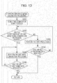
- the sine wave information decoding unit 105 performs the sine wave signal generation processing illustrated in Fig. 13 .
- the sine wave signal generation processing corresponding to the processing at the step S158 will be described with reference to the flowchart in Fig. 13 .
- the position calculating unit 221 in the sine wave information decoding unit 105 calculates the combination start position of the sine wave signal from the noise boundary position supplied from the noise envelope information decoding unit 104 and the difference information obtained from the sine wave information. That is to say, the difference in the time between the combination start position and the noise boundary position is subtracted from the time from the start position of the frame being processed until the noise boundary position, the time from the start position of the frame until the combination start position of the sine wave signal is obtained, and the timing (sample) of the combination start position is identified.
- the sine wave information decoding unit 105 calculates a more accurate combination start position of the sine wave signal from the difference information included in the sine wave information signal and the noise boundary position. As a result, the combination of the sine wave signal is started at a more accurate position in one frame, and so audio at a higher audio quality may be obtained.
- the encoding device is configured as illustrated in Fig. 14 .
- the components in Fig. 14 that correspond to those in Fig. 1 have the same reference numerals, and so their descriptions will be omitted as appropriate.
- An encoding device 251 in Fig. 14 and the encoding device 11 are different in that a peak detection unit 261 and a difference calculating unit 262 are newly provisioned in the sine wave information generating unit 26 of the encoding device 251, and so are the same regarding other components.
- the envelope information supplied from the envelope information generating unit 24 to the noise envelope information generating unit 25 is also supplied from the noise envelope information generating unit 25 to the sine wave information generating unit 26.
- the peak detection unit 261 detects the peak position of the high frequency signal envelope on the basis of the envelope information supplied from the noise envelope information generating unit 25.
- the difference calculating unit 262 calculates the difference between the combination start position of the sine wave signal detected by the position detection unit 62 and the peak position of the high frequency signal envelope.
- the sine wave information generating unit 26 supplies the information made up from the difference information representing the difference with the peak position calculated by the difference calculating unit 262 and the information representing whether or not the sine wave signal has been detected to the encoding stream generating unit 27 as the sine wave information.
- the encoding processing performed by the encoding device 251 will be described with reference to the flowchart in Fig. 15 . Further, the processing of the step S211 through the step S218 are the same as the step S11 through the step S18 in Fig. 2 , and so their description is omitted. However, at the step S214, the generated envelope information is also supplied to the sine wave information generating unit 26 from the envelope information generating unit 24 through the noise envelope information generating unit 25.
- the peak detection unit 261 in the sine wave information generating unit 26 detects the peak position of the high frequency signal envelope on the basis of the envelope information supplied from the noise envelope information generating unit 25. For example, the position where the gain of the high frequency signal envelope represented by the envelope information is at a maximum is detected as the peak position of the high frequency signal envelope.
- the difference calculating unit 262 calculates, for each band at the high frequency side, the difference between the combination start position of the sine wave signal detected by the position detection unit 62 and the peak position of the envelope detected by the peak detection unit 261.
- the time (number of samples) from the start position of the sine wave combination until the peak position is calculated as the difference.
- the horizontal axis in the figure represents the timeline.
- an arrow FS21 and an arrow FE21 in Fig. 16 represent the start position and the end position of the frame, respectively.
- the envelope of the high frequency signal is represented by a dotted line, and the position represented by an arrow P1 in the frame represents the peak position of this envelope.
- the combination start position of the sine wave signal is the position represented by an arrow G21, and the combination start position is positioned before the peak position of the envelope.
- the sine wave signal is combined in the zone from the combination start position represented by the arrow G21 until the end position of the frame.
- the length of time (temporal distance) from the combination start position represented by the arrow G21 until the peak position of the high frequency signal envelope represented by the arrow P1 is designated as the difference with the peak position.
- the time from the combination start position until the peak position is an integral multiple of the timeslot length.
- the sine wave information generating unit 26 generates the sine wave information for each band at the high frequency side, and supplies this to the encoding stream generating unit 27.
- the sine wave information generating unit 26 designates the information made up from the information representing whether or not the sine wave has been detected from the high frequency band and the difference information between the combination start position and the peak position as the sine wave information.
- the encoding unit 63 in the sine wave information generating unit 26 performs the variable length encoding of the difference information with the peak position.
- the sine wave information generating unit 26 supplies the sine wave information made up from the difference information processed by the variable length encoding and the information representing whether or not the sine wave signal has been detected to the encoding stream generating unit 27.
- the processing at a step S222 through a step S224 is performed and the encoding processing terminates, and as this processing is the same as the processing at the step S20 through the step S22 in Fig. 2 , so its description is omitted.
- the encoding device 251 generates and outputs the encoding stream made up from the low frequency signal, the envelope information, the noise envelope information, and the sine wave information. At this time, by detecting a more accurate combination start position of the sine wave signal and generating sine wave information including the difference information used for identifying this combination start position, a more accurate combination of the sine wave signal may be performed during decoding, and so audio at a higher audio quality may be obtained as a result.
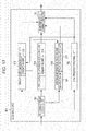
- a decoding device that receives the encoding stream transmitted from the encoding device 251, and obtains the audio signal from the encoding stream is configured as illustrated in Fig. 17 .
- the components in Fig. 17 that correspond to those in Fig. 5 have the same reference numerals, and so their descriptions will be omitted as appropriate.
- a decoding device 301 in Fig. 17 and the decoding device 91 are different in that a position calculating unit 311 is newly provisioned in the sine wave information decoding unit 105 of the decoding device 301, and so are the same regarding other components.
- the position calculating unit 311 in the decoding device 301 calculates the combination start position of the sine wave signal from the difference information obtained from the sine wave information and the envelope information supplied from the envelope information decoding unit 103.
- step S251 through a step S257 are the same as the step S51 through the step S57 in Fig. 6 , and so their description is omitted.
- the sine wave information decoding unit 105 performs the sine wave signal generation processing, generates the sine wave signal for each band at the high frequency side, and supplies this to the band pass combination filter 106. Further, details of the sine wave signal generation processing will be described later.
- the processing at a step S259 is performed, and the decoding processing terminates, and as the processing at the step S259 is the same as the step S59 in Fig. 6 , its description is omitted.
- the sine wave information decoding unit 105 performs the sine wave signal generation processing illustrated in Fig. 19 .
- the sine wave signal generation processing corresponding to the processing at the step S258 will be described with reference to the flowchart in Fig. 19 .
- the position calculating unit 311 in the sine wave information decoding unit 105 calculates the combination start position of the sine wave signal from the envelope information supplied from the envelope information decoding unit 103 and the difference information obtained from the sine wave information.
- the position where the gain of the high frequency signal envelope represented in the envelope information is at a maximum is calculated by the position calculating unit 311 as the peak position of the high frequency signal envelope. Then, the position calculating unit 311 subtracts the difference in the time between the combination start position and the peak position is subtracted from the time from the start position of the frame being processed until the peak position, the time from the start position of the frame until the combination start position of the sine wave signal, and the timing (sample) of the combination start position is identified.
- step S282 After the combination start position is calculated, the processing of a step S282 through a step S286 is performed, and the sine wave signal generation processing terminates, and as this processing is the same as the processing of the step S81 through the step S85 in Fig. 7 , their descriptions are omitted. After the sine wave signal generation processing terminates in this way, the processing proceeds to a step S259 in Fig. 18 .
- the sine wave information decoding unit 105 calculates a more accurate combination start position of the sine wave signal from the difference information included in the sine wave information and the peak position of the high frequency signal envelope. As a result, the combination of the sine wave signal is started at a more accurate position in one frame, and so audio at a higher audio quality may be obtained.
- information representing the peak position may be included in the sine wave information.
- the sine wave information generating unit 26 in the encoding device 251 generates the sine wave information including the information representing the peak position
- the position calculating unit 311 in the decoding device 301 calculates the combination start position from the difference information and the information representing the peak position included in the sine wave information.
- the sine wave information included one type of previously determined information from among the combination start position, the difference information with the noise boundary position, or the difference information with the peak position, the information among these with the smallest encoding amount may be selected to be included in the sine wave information.
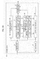
- the encoding device is configured as illustrated in Fig. 20 , for example. Further, the components in Fig. 20 that correspond to those in Fig. 1 or Fig. 14 have the same reference numerals, and so their descriptions will be omitted as appropriate.
- An encoding device 341 in Fig. 20 and the encoding device 11 in Fig. 1 are different in that a peak detection unit 261, a difference calculating unit 351, and a selection unit 352 are newly provisioned in the sine wave information generating unit 26 of the encoding device 341, and so are the same regarding other components.
- the envelope information supplied from the envelope information generating unit 24 to the noise envelope information generating unit 25 is also supplied from the noise envelope information generating unit 25 to the sine wave information generating unit 26, and the peak detection unit 261 detects the peak position of the high frequency signal envelope on the basis of the envelope information.
- the difference calculating unit 351 calculates the difference between the combination start position of the sine wave signal detected by the position detection unit 62 and the peak position of the high frequency signal envelope. The difference calculating unit 351 also calculates the difference between the combination start position and the noise boundary position.
- the selection unit 352 selects the information that will result in the smallest encoding amount after the variable length encoding from among the combination start position, the difference information with the peak position, or the difference information with the noise boundary position.
- the sine wave information generating unit 26 supplies the information made up from the information representing the result of the selection by the selection unit 352, the information selected by the selection unit 352, and the information representing whether or not the sine wave signal has been detected, to the encoding stream generating unit 27 as sine wave information.
- step S311 through the step S321 are the same as the step S111 through the step S121 in Fig. 9 , and so their description is omitted.
- the difference calculating unit 351 in the sine wave information generating unit 26 calculates the difference between the combination start position of the sine wave signal detected by the position detection unit 62 and the noise boundary position for each band at the high frequency side. Also, at the step S314, the generated envelope information is also supplied to the sine wave information generating unit 26 from the envelope information generating unit 24 through the noise envelope information generating unit 25.
- the peak detection unit 261 in the sine wave information generating unit 26 detects, for each band at the high frequency side, the peak position of the high frequency signal envelop on the basis of the envelop information supplied from the noise envelope information generating unit 25.
- the difference calculation unit 351 calculates, for each band at the high frequency side, the difference between the combination start position of the sine wave signal detected by the position detection unit 62 and the peak position of the envelope detected by the peak detection unit 261.
- the selection unit 352 selects, for each band at the high frequency side, the information that will result in the smallest encoding amount after the variable length encoding from among the combination start position, the difference information between the combination start position and the peak position, or the difference information between the combination start position and the noise boundary position. Then, the selection unit 352 generates the selection information representing the result of this selection. At this time, only the encoding amount of the combination start position or similar may be calculated and compared, or the actual combination start position or similar information may be processed by the variable length encoding, and this encoding amount may be compared.
- the sine wave information generating unit 26 generates the sine wave information for each band at the high frequency side, and supplies this to the encoding stream generating unit 27.
- the sine wave information generating unit 26 designates the information made up from the information representing whether or not the sine wave signal has been detected from the high frequency band, the selection information, and the information representing the selection information as the sine wave information.
- the encoding unit 63 in the sine wave information generating unit 26 performs the variable length encoding of the selection information and the information representing the selection information.
- the sine wave information generating unit 26 supplies the sine wave information made up from the selection information and the information representing the selection information processed by the variable length encoding and the information representing whether or not the sine wave signal has been detected to the encoding stream generating unit 27.
- the information representing the selection information is the difference information between the combination start position and the peak position
- the information made up from the selection information, the difference information with the peak position, and the information representing whether or not the sine wave signal has been detected is designated as the sine wave information.
- the sine wave information including the information with the smallest encoding amount that identifies the combination start position of the sine wave signal, the encoding amount of the encoding stream may be further reduced.
- the processing at a step S326 is performed and the encoding processing terminates, and as this processing is the same as the processing at the step S224 in Fig. 15 , its description is omitted.
- the encoding device 341 generates and outputs the encoding stream made up from the low frequency signal, the envelope information, the noise envelope information, and the sine wave information.
- the sine wave information including the information with the smallest encoding amount from among the information that identifies the combination start position of the sine wave signal, the data amount of the encoding stream to be transferred may be reduced, and at the same time, a more accurate combination of the sine wave signal may be performed during decoding at the decoding side of the audio signal. As a result, audio at a higher audio quality may be obtained.
- a decoding device that receives the encoding stream transmitted from the encoding device 341, and obtains the audio signal from the encoding stream is configured as illustrated in Fig. 22 , for example. Further, the components in Fig. 22 that correspond to those in Fig. 5 have the same reference numerals, and so their descriptions will be omitted as appropriate.
- a decoding device 381 in Fig. 22 and the decoding device 91 are different in that a position calculating unit 391 is newly provisioned in the sine wave information decoding unit 105 of the decoding device 381, and so are the same regarding other components.
- the position calculating unit 391 in the decoding device 381 calculates the combination start position of the sine wave signal from either the difference information with the peak position or the difference information with the noise boundary position obtained from the sine wave information, depending on the selection information included in the sine wave information.
- step S351 through a step S356 are the same as the step S51 through the step S56 in Fig. 6 , and so their description is omitted.
- the noise envelope information decoding unit 104 supplies the information representing the noise boundary position included in the noise envelope information obtained by the decoding to the sine wave information decoding unit 105.
- the sine wave information decoding unit 105 decodes the sine wave information from the encoding stream decoding unit 101. For example, the selection information included in the sine wave information, and the information used to obtain the combination start position identified by the selection information, are decoded.
- the sine wave information decoding unit 105 performs the sine wave signal generation processing, generates the sine wave signal for each band at the high frequency side, and supplies this to the band pass combination filter 106. Further, details of the sine wave signal generation processing will be described later.
- the processing at a step S359 is performed, and the decoding processing terminates, and as the processing at the step S359 is the same as the step S59 in Fig. 6 , its description is omitted.
- the sine wave information decoding unit 105 performs the sine wave signal generation processing illustrated in Fig. 24 .
- the sine wave signal generation processing corresponding to the processing at the step S358 will be described with reference to the flowchart in Fig. 24 .
- the position calculating unit 391 determines whether or not the information used to obtain the combination start position of the sine wave signal represented by the selection information is the information actually representing the combination start position. That is to say, it is determined whether or not the combination start position is included in the sine wave information.
- step S381 determines whether the information represented by the selection information is the information representing the combination start position of the sine wave signal.
- step S381 determines whether the information represented by the selection information is not be the information representing the combination start position of the sine wave signal.
- the position calculating unit 391 determines whether or not the information used to obtain the combination start position of the sine wave signal represented by the selection information is the difference information between the combination start position and the noise boundary position. That is to say, it is determined whether or not the difference information with the noise boundary position is included in the sine wave information.
- the position calculating unit 391 in the sine wave information decoding unit 105 calculates the combination start position of the sine wave signal from the noise boundary position supplied from the noise envelope information decoding unit 104 and the difference information with the noise boundary position obtained from the sine wave information. After the combination start position is calculated, the processing proceeds to the step S385.
- the processing proceeds to a step S384.
- the position calculating unit 391 in the sine wave information decoding unit 105 calculates the combination start position of the sine wave signal form the envelope information supplied from the envelope information decoding unit 103 and the difference information with the peak position of the high frequency signal envelope obtained from the sine wave information.
- the position calculating unit 391 detects the position where the gain in the high frequency signal envelope represented by the envelope information is at a maximum as the peak position of the high frequency signal envelope. Then, the position calculating unit 391 subtracts the difference in time between the combination start position and the peak position from the time from the start position of the frame to be processed until the peak position, obtains the time from the start position of the frame until the combination start position of the sine wave signal, and identifies the timing (sample) of the combination start position. After the combination start position is calculated, the processing proceeds to the step S385.
- the processing proceeds to the step S385.
- the processing of the step S382 through a step S389 is performed, and the sine wave signal generation processing terminates, and as this processing is the same as the processing of the step S81 through the step S85 in Fig. 7 , their descriptions are omitted.
- the processing proceeds to a step S359 in Fig. 23 .
- the sine wave information decoding unit 105 identifies the information included in the sine wave information from the selection information, and arbitrarily calculates a more accurate combination start position of the sine wave signal according to the result of this specification. As a result, the combination of the sine wave signal is started at a more accurate position in one frame, and so audio at a higher audio quality may be obtained.
- the series of processing previously described may be executed by hardware, or may be executed by software.
- a program configuring this software may be installed into a computer built with specialized hardware, or by installing various programs from a program recording medium into a general purpose personal computer, for example, that may execute various functions.
- Fig. 25 is a block diagram illustrating a configuration example of computer hardware for executing the previously described series of processing as a program.
- a CPU 501, ROM (Read Only Memory) 502, and RAM (Random Access Memory) 503, are connected together in the computer by a bus 504.
- an input/output interface 505 is connected to the bus 504.
- Devices connected to the input/output interface 505 include an input unit 506 made up of a keyboard, a mouse, a microphone, etc., an output unit 507 made up of a display, speaker, etc., a recording unit 508 made up of a hard disk, non-volatile memory, etc., a communication unit 509 made up of a network interface, etc., and a drive 510 for driving a magnetic disk, an optical disk, a magneto-optical disk, or a removable media 511 such as semiconductor memory.
- the CPU 501 loads and executes the program installed in the recording unit 508 into the RAM 503 through the input/output interface 505 and bus 504, for example, to perform the previously described series of processing.
- the program executed by the computer (CPU 501) may be recorded in the removable media 511, which is a form of packaged media configured of, for example, a magnetic disk (including a floppy disk), an optical disk (such as CD-ROM (Compact Disc-Read Only Memory) or DVD (Digital Versatile Disc)), a magneto-optical disk, or semiconductor memory, etc., or may be supplied via a wired or wireless transmission medium such as a local area network, the Internet, or a digital satellite broadcast.
- a magnetic disk including a floppy disk
- an optical disk such as CD-ROM (Compact Disc-Read Only Memory) or DVD (Digital Versatile Disc)
- magneto-optical disk or semiconductor memory, etc.
- semiconductor memory etc.
- a wired or wireless transmission medium such as a local area network, the Internet, or a digital satellite broadcast.
- the program may be installed to the recording unit 508 through the input/output interface 505 by installing the removable media 511 to the drive 510. Also, the program may be installed to the recording unit 508 after being received by the communication unit 509 via the wired or wireless transfer medium. Also, the program may be previously installed in the ROM 502 or the recording unit 508.
- the program executed by the computer may perform the processing in time-sequence order as described in the present specification, may perform the processing in parallel, or at a necessary timing such as when a call is performed.
Description
- The present invention relates to a signal processing device, method, and program, and particularly, relates to a signal processing device, program, and method that enables audio to be obtained at a higher audio quality in a case of decoding encoding audio signals.
- In general, audio signal encoding methods such as HE-AAC (High Efficiency MPEG (Moving Picture Experts Group) 4 AAC (Advanced Audio Coding)) (international standard ISO/IEC 14496-3) are known. With such an encoding method, a high frequency feature encoding technology such as SBR (Spectral Band Replication) is used (for example, refer to PTL 1).
- According to SBR, when encoding audio signals, SBR information is output for generating high frequency components of the audio signal (hereafter, referred to as high frequency signal) together with low frequency components of the encoded audio signal (hereafter, low frequency signal). At the decoding device, while decoding the encoded low frequency signal, the high frequency signal is generated by using the low frequency signal obtained by the decoding and the SBR information, and so the audio signal made up of the low frequency signal and the high frequency signal is obtained.
- This kind of SBR information includes envelope information mainly representing an envelope form for the high frequency components, and noise envelope information representing for obtaining a noise signal added during the generation of the high frequency components at the decoding device.
- Here, the noise envelope information includes information representing a boundary position for dividing each SBR frame of the noise signal included in the high frequency components into two zones (hereafter, referred to as the noise boundary position), and information representing gain of noise signals in each zone. Therefore, at the decoding device, a gain adjustment is performed on each zone divided by the noise boundary position on a predetermined noise signal on the basis of the noise envelope information to establish a final noise signal. Further, with SBR, it is also possible to set the gain on the entire SBR frame without dividing the SBR frame of the noise signal into two zones.
- When decoding the audio signal, the decoding device generates the high frequency components by combining a pseudo high frequency signal obtained from the low frequency signal and the envelope information, and the noise signal obtained from the noise envelope information, and generates the audio signal from the obtained high frequency components and the low frequency signal.
- Also, with SBR, an encoding using sine wave synthesis is performed on an audio signal with a high tone characteristic. That is to say, when generating the high frequency components at the decoding side, a sine wave signal of a particular frequency is added to the pseudo high frequency signal in addition to the noise signal. In this case, the signal obtained from combining the pseudo high frequency signal, the noise signal, and the sine wave signal is set to the high frequency signal obtained as a prediction.
- When using a sine wave signal to predict the high frequency components, a sine wave information representing the existence/non-existence of the sine wave signal in the SBR frame is included in the SBR information. Specifically, the combination start position of the sine wave signal used during decoding is either the start position of the SBR frame or the noise boundary position, and the sine wave information is made up of binary information representing the existence/non-existence of a sine wave signal combination in each zone of the SBR frame divided by the noise boundary position.
- In this way, the noise signal and the sine wave signal added to the pseudo high frequency signal are components that are difficult to reproduce from the envelope information within the high frequency components of the source audio signal. Therefore, by combining the noise signal and the sine wave signal at a suitable position in the pseudo high frequency signal, it is possible to predict the high frequency components with higher accuracy, and it is possible to reproduce audio at a higher audio quality by performing band pass expansion using the high frequency components obtained by prediction.
- PTL 1: Japanese Unexamined Patent Application Publication (Translation of
PCT Application) No. 2001-521648 -
US 2005/0080621 A1 relates to a decoding apparatus and decoding method for an audio bandwidth expansion system for generating a wideband audio signal from a narrowband audio signal by adding additional information containing little information, and relates to technology enabling this system to provide high audio quality playback with few calculations - AES article as written by WOLTERS M ET AL entitled: "A closer look into MPEG-4 High Efficiency AAC",explains MPEG SBR and its integration into the existing MPEG-4 bitstream format.
- The invention is as defined by the appended claims.
- However, when using a sine wave signal to predict the high frequency components, the combination start position of the sine wave signal is set as the SBR frame start position or the noise boundary position, which may cause variance in the emergence start position of the sine wave components in the original audio signal, in some cases. Thus, it is not possible to reproduce the high frequency components with high accuracy, and may cause degradation in the audible perception of the audio signal obtained from the decoding.
- Particularly with SBR, the frame length is fixed and not dependent on the sampling rate of the audio signal to be encoded, and so when the sampling rate is low, the absolute time length for one frame becomes longer. For this reason, the amount of variance (difference) in absolute time between the emergence start position of the sine wave components in the source audio signal and the combination start position of the sine wave signal to be combined during decoding increases, and quantization noise becomes noticeable at these zones of variance.
- The present technology has been made taking this kind of situation into consideration to enable the obtainment of audio at a higher audio quality when decoding audio signals. Solution to Problem
- The invention is as defined by the appended claims.
- According to the first aspect and the second aspect of the present technology, audio may be obtained at a higher audio quality when decoding an audio signal.
-
- [
Fig. 1] Fig. 1 is a diagram illustrating a configuration example of a first Embodiment of an encoding device. - [
Fig. 2] Fig. 2 is a flowchart describing an encoding processing. - [
Fig. 3] Fig. 3 is a diagram illustrating a combination start position of a sine wave signal. - [
Fig. 4] Fig. 4 is a diagram illustrating a combination start position of a sine wave signal. - [
Fig. 5] Fig. 5 is a diagram illustrating a configuration example of the first Embodiment of a decoding device. - [
Fig. 6] Fig. 6 is a flowchart describing a decoding processing. - [
Fig. 7] Fig. 7 is a flowchart describing a processing to generate the sine wave signal. - [
Fig. 8] Fig. 8 is a diagram illustrating a configuration example of another encoding device. - [
Fig. 9] Fig. 9 is a flowchart describing an encoding processing. - [
Fig. 10] Fig. 10 is a diagram describing a combination start position of the sine wave signal. - [
Fig. 11] Fig. 11 is a diagram illustrating a configuration example of another decoding device. - [
Fig. 12] Fig. 12 is a flowchart describing a decoding processing. - [
Fig. 13] Fig. 13 is a flowchart describing a processing to generate the sine wave signal. - [
Fig. 14] Fig. 14 is a diagram illustrating a configuration example of another encoding device. - [
Fig. 15] Fig. 15 is a flowchart describing an encoding processing. - [
Fig. 16] Fig. 16 is a diagram describing a combination start position of the sine wave signal. - [
Fig. 17] Fig. 17 is a diagram illustrating a configuration example of another decoding device. - [
Fig. 18] Fig. 18 is a flowchart describing a decoding processing. - [
Fig. 19] Fig. 19 is a flowchart describing a processing to generate the sine wave signal. - [
Fig. 20] Fig. 20 is a diagram illustrating a configuration example of another encoding device. - [
Fig. 21] Fig. 21 is a flowchart describing an encoding processing. - [
Fig. 22] Fig. 22 is a diagram illustrating a configuration example of another decoding device. - [
Fig. 23] Fig. 23 is a flowchart describing a decoding processing. - [
Fig. 24] Fig. 24 is a flowchart describing a processing to generate the sine wave signal. - [
Fig. 25] Fig. 25 is a diagram illustrating a configuration example of a computer. - Hereafter, the embodiments applying the present technology will be described with reference to the drawings.
-
Fig. 1 is a diagram illustrating a configuration example of a first Embodiment of an encoding device applying the present technology. - An
encoding device 11 is configured with adownsampler 21, a lowfrequency encoding unit 22, a bandpass division filter 23, an envelopeinformation generating unit 24, a noise envelopeinformation generating unit 25, a sine waveinformation generating unit 26, and an encodingstream generating unit 27. Theencoding device 11 encodes and outputs an input audio signal, and the audio signal input into theencoding device 11 is supplied to thedownsampler 21 and the bandpass division filter 23. - The
downsampler 21 extracts the low frequency signal, which is the low frequency components of the audio signal, by downsampling the input audio signal, and supplies this to the lowfrequency encoding unit 22 and the noise envelopeinformation generating unit 25. Further, hereafter, the frequency band components at or below a certain frequency of the audio signal are referred to as the low frequency components, and the frequency band components higher than the low frequency components of the audio signal are referred to as the high frequency components. - The low
frequency encoding unit 22 encodes the low frequency signal supplied from thedownsampler 21, and supplies this to the encodingstream generating unit 27. - The band
pass division filter 23 conducts a filter processing on the input audio signal, and performs a band pass division of the audio signal. As a result of this band pass division, the audio signal is divided into a signal of multiple band components. Further, hereafter, each band signal configuring the high frequency components from within each band signal obtained by the band pass division is referred to as the high frequency signal. The bandpass division filter 23 supplies the high frequency signal from the high frequency side of each band obtained by the band pass division to the envelopeinformation generating unit 24, the noise envelopeinformation generating unit 25, and the sine waveinformation generating unit 26. - The envelope
information generating unit 24 generates an envelope information representing a form of an envelope (envelope) for the high frequency signal of the band for each band on the high frequency side on the basis of the high frequency signal supplied from the bandpass division filter 23, and then supplies this to the noise envelopeinformation generating unit 25. Also, the envelopeinformation generating unit 24 is provisioned with anencoding unit 41, and theencoding unit 41 encodes the envelope information generated by the envelopeinformation generating unit 24, and supplies this to the encodingstream generating unit 27. - The noise envelope
information generating unit 25 generates a noise envelope information while receiving information from the sine waveinformation generating unit 26 as necessary, on the basis of the high frequency signal from the bandpass division filter 23 and the envelope information from the envelopeinformation generating unit 24. - Here, the noise envelope information is information made up from information representing a boundary position (noise boundary position) for dividing the noise signal included in the high frequency components of the audio signal, and information representing the noise signal gain for each zone divided at the noise boundary position. Further, the noise signal is a previously determined signal.
- Also, the noise envelope
information generating unit 25 is provisioned with asignal generating unit 51, aboundary calculating unit 52, and anencoding unit 53. When generating noise envelope information, thesignal generating unit 51 predicts the high frequency side of the audio signal for each band component on the basis of the low frequency signal from thedownsampler 21 and the envelope information from the envelopeinformation generating unit 24. - The
boundary calculating unit 52 determines the noise boundary position used for dividing the noise signal into multiple zones on the basis of the noise signal envelope obtained from the high frequency signal and a pseudo high frequency signal, which is the result of the high frequency side of each band pass component predicted during the generation of the noise envelope information. Theencoding unit 53 encodes the noise envelope information generated by the noise envelopeinformation generating unit 25, and supplies this to the encodingstream generating unit 27. - The sine wave
information generating unit 26 generates sine wave information used for obtaining the sine wave signal included in the band for each band at the high frequency side while receiving the information from the noise envelopeinformation generating unit 25 as necessary, on the basis of the high frequency signal supplied from the bandpass division filter 23. - Here, the sine wave information is information made up from information representing the existence/non-existence of a sine wave signal included in the high frequency components of the audio signal, and information used for identifying the emergence start position of the sine wave signal. That is to say, the sine wave information may be information made up from information representing the existence/non-existence of a sine wave signal to be combined with the pseudo high frequency components during decoding of the audio signal, and information representing the combination start position of the sine wave signal.
- Also, then sine wave
information generating unit 26 is provisioned with a sinewave detection unit 61, aposition detection unit 62, and anencoding unit 63. The sinewave detection unit 61 detects the existence/non-existence of the sine wave components from the high frequency signal during generation of the sine wave information. - When generating sine wave information, the
position detection unit 62 detects the combination start position indicating where the combination of the sine wave signal should start, that is to say, the emergence start position of the sine wave signal, on the basis of the high frequency signal from the bandpass division filter 23. Theencoding unit 63 encodes the sine wave information generated by the sine waveinformation generating unit 26, and supplies this to the encodingstream generating unit 27. - The encoding
stream generating unit 27 encodes the low frequency signal from the lowfrequency encoding unit 22, the envelope information from the envelopeinformation generating unit 24, the noise envelope information from the noise envelopeinformation generating unit 25, and the sine wave information from the sine waveinformation generating unit 26, and outputs the encoding stream obtained from this encoding. That is to say, the low frequency signal, the envelope information, the noise envelope information, and the sine wave information are multiplexed into the encoding stream. - Next, the operation of the
encoding device 11 will be described. - When the audio signal is input into the
encoding device 11, and instructed to encode the audio signal, theencoding device 11 performs the encoding processing to perform the encoding of the audio signal, and outputs the encoding stream obtained as the result. Hereafter, the encoding processing by theencoding device 11 will be described with reference to the flowchart inFig. 2 . - At a step S11, the
downsampler 21 downsamples the input audio signal to generate the low frequency signal, and supplies this to the noise envelopeinformation generating unit 25 and the lowfrequency encoding unit 22. - At a step S12, the low
frequency encoding unit 22 encodes the low frequency signal supplied from thedownsampler 21, and supplies this to the encodingstream generating unit 27. For example, the low frequency signal is encoded by an encoding method such as MPEG4 AAC, MPEG2 AAC, CELP (Code Exited Linear Prediction), TCX (Transform Coded Excitation), or AMR (Adaptive Multi-Rate). - At a step S13, the band
pass division filter 23 divides the input audio signal into bands, and the high frequency components obtained as the result are supplied to the envelopeinformation generating unit 24 through the sine waveinformation generating unit 26. For example, high frequency signals may be obtained as high frequency components from 64 different bands. - At a step S14, the envelope
information generating unit 24 generates the envelope information for each band on the basis of the high frequency signal for each band supplied from the bandpass division filter 23. For example, the envelopeinformation generating unit 24 may designate a zone made up of 32 samples of the high frequency signal as one frame, and generate the envelope information for each band per frame. - Specifically, the envelope
information generating unit 24 obtains an average sample value of two samples of the high frequency signal neighboring on a time line in one frame, and this average value becomes the new high frequency signal sample value. As a result, the high frequency signal for one frame is converted from a 32-sample signal to a 16-sample signal. - Next, the envelope
information generating unit 24 performs a difference encoding on the high frequency signal that is now 16 samples, and the information obtained as the result becomes the envelope information. For example, the difference between the sample value of two high frequency signal samples to be processed neighboring on a time line is obtained by the difference encoding, and this difference becomes the envelope information. Also, the envelope information may be made up of the difference between the sample value of a sample of the high frequency signal of the band to be processed and the sample value of a sample in a band adjacent to that band, in the same position as the high frequency signal band, for example. - The envelope information obtained in this way is the information representing the form of the envelope for one frame of the high frequency signal. The
encoding unit 41 performs a variable length encoding such as Huffman encoding on the generated envelope information, and supplies the encoded envelope information to the encodingstream generating unit 27. Also, the envelopeinformation generating unit 24 supplies the envelope information to the noise envelopeinformation generating unit 25. - Further, hereafter, the high frequency signal will continue to be described as that processed in units of one frame configured of 32 samples. Also, hereafter, the zone configured from two samples of the high frequency signal (audio signal) will be called one timeslot.
- At a step S15, the
signal generating unit 51 in the noise envelopeinformation generating unit 25 generates the pseudo high frequency signal for each band at the high frequency side on the basis of the envelope information supplied from the envelopeinformation generating unit 24 and the low frequency signal supplied from thedownsampler 21. - For example, the
signal generating unit 51 extracts the zone for one frame of a predetermined band of the low frequency signal, and manipulates the extracted low frequency signal into the envelope form represented by the envelope information. That is to say, the sample value of the sample of the low frequency signal is increased or decreased so that the position gain corresponding to the sample fits in the envelope represented by the envelope information, and the signal obtained as the result becomes the pseudo high frequency signal. - The pseudo high frequency signal obtained in this way has the almost the same envelope form as the envelope of the actual high frequency signal represented by the envelope information. That is to say, the pseudo high frequency signal is generated from the low frequency signal and the envelope information.
- At a step S16, the noise envelope
information generating unit 25 extracts the difference between the high frequency signal and the pseudo high frequency signal for each band at the high frequency side, and obtains the envelope for the noise signal (hereafter, referred to as the noise envelope). - Further, more specifically, the noise envelope obtained at step S16 is a virtual noise envelope. The receiving side of the encoding stream output from the
encoding device 11 predicts the high frequency components of the audio signal during the decoding of the audio signal, but this prediction is performed by combining of the pseudo high frequency signal, the noise signal, and the sine wave signal. - That is to say, the high frequency components of the actual audio signal are assumed to include the pseudo high frequency signal, the noise signal, and the sine wave signal. Here, at the step S16, the difference between the high frequency signal and the pseudo high frequency signal is obtained, and this difference should be the combination of the noise signal and the sine wave signal. Thus, the difference obtained in this way is considered as the envelope of the noise signal including the sine wave signal.
- The noise envelope
information generating unit 25 supplies the virtual noise envelope for each band at the high frequency side obtained as previously described to the sine waveinformation generating unit 26. - At a step S17, the sine
wave detection unit 61 in the sine waveinformation generating unit 26 detects the sine wave components from the high frequency signal for each band on the basis of the virtual noise envelope supplied from the noise envelopeinformation generating unit 25. - For example, the sine
wave detection unit 61 conducts a frequency conversion on the virtual noise envelope, and converts the noise envelope into frequency components. Then, when there are frequency spikes having high power in the obtained frequency components, the sinewave detection unit 61 recognizes these frequency components as the sine wave components. Specifically, when the difference between the power of the frequency under observation and the power of other surrounding frequencies is at or above a predetermined threshold, the frequency under observation is recognized as the sine wave component. The sine wave signal for the frequency detected in this way is determined as the sine wave signal included in the actual high frequency components. - At a step S18, the
position detection unit 62 in the sine waveinformation generating unit 26 detects, for each band, the combination start position where the sine wave signal, which is the detected sine wave component, should be combined on the basis of the high frequency signal supplied from the bandpass division filter 23. - For example, the
position detection unit 62 obtains the difference between the average sample value of the samples included in one timeslot of the high frequency signal, in units of timeslots, and the average sample value of samples included in one timeslot of the detected sine wave signal. Then, theposition detection unit 62 determines the combination start position looking from the beginning of the zone for one frame as the final position (start position of the timeslot or the final position of the sample) where the value of the obtained difference is at or above a predetermined threshold. This combination start position is the emergence start position of the sine wave signal included in the actual high frequency signals, from a timing after the combination start position, the difference in the average sample values of the high frequency signal and the sine wave signal should decrease. - Also, for each band at the high frequency side, the sine wave
information generating unit 26 supplies the information representing whether or not the sine wave has been detected from the bands, the information representing the frequency and power of the detected sine wave signal, and the combination start position to the noise envelopeinformation generating unit 25. - At a step S19, the sine wave
information generating unit 26 generates the sine wave information for each band at the high frequency side, and supplies this to the encodingstream generating unit 27. - For example, the sine wave
information generating unit 26 designates the information made up from the information representing whether or not the sine wave signal has been detected from the high frequency band and the combination start position as the sine wave information. Also, during the generation of the sine wave information, theencoding unit 63 in the sine waveinformation generating unit 26 performs the variable length encoding of the information representing the combination start position. - Here, the information representing whether or not the sine wave signal has been detected is, more specifically, information representing which frequency in the high frequency band is the sine wave component. For example, when multiple sine wave signals are detected from the high frequency band, the information used for identifying the frequencies of these sine wave signals is designated as the information representing whether or not the sine wave signals were detected. Also, when multiple sine wave signals are detected from the high frequency band, information representing the combination start position is generated for each sine wave signal.
- Also, when the sine wave component is not detected from the high frequency band, the sine wave information made up only of information representing whether or not the sine wave signal has been detected is transmitted to the decoding side. That is to say, the sine wave information not including information representing the combination start position is transmitted.
- Further, the
encoding device 11 may select whether or not to transmit the sine wave information to the decoding side per frame. In this way, by enabling the transmission of the sine wave information to be selectable, transfer efficiency of the encoding stream in increased, and at the same time, a resetting of the time information of the sine wave components may be performed. As a result, when starting the decoding processing from an arbitrary frame within the stream on the decoding side of the encoding stream, the sine wave component from the frame including the information representing the combination start position may be started. - Further, as illustrated in
Fig. 3 for example, the combination start position on the decoding side has conventionally been either the start position of the frame or the noise boundary position. Further, the horizontal axis in the figure represents the time line. Also, an arrow FS1 and an arrow FE1 inFig. 3 represent the start position and end position of the frame, respectively. - According to the example in
Fig. 3 , the position represented by an arrow N1 is the noise boundary position, and the combination start position of the sine wave signal is also in the same position as the noise boundary position. Therefore, the sine wave signal is combined in a zone from the position represented by the arrow N1 until the end position of the frame. - However, when the position that sine wave signal included in the actual high frequency components arrives is after the noise boundary position represented by the arrow N1, for example, at the decoding side, unnecessary sine wave components are added in the space from the noise boundary position to the emergence start position of the actual sine wave signal. In this case, there is an unpleasant audible sensation in the audio signal obtained by the decoding, and audio at a high audio quality is unable to be obtained.
- Regarding this, as illustrated in
Fig. 4 , according to theencoding device 11, the combination start position output to the decoding side is not limited to being the same as the noise boundary position. Further, the horizontal axis in the figure represents the time line. Also, an arrow FS2 and arrow FE2 inFig. 4 represent the start position and the end position of the frame, respectively. - According to the example in
Fig. 4 , the position represented by an arrow N2 represents the noise boundary position. Also, the combination start position of the sine wave signal is the position represented by an arrow G1, and this combination start position is before the noise boundary position. According to this example, the sine wave signal is combined in the zone from the combination start position represented by the arrow G1 until the end position of the frame. - Also, in this case, the information representing the length of time (time distance) from the start position of the frame represented by the arrow FS2 until the combination start position represented by the arrow G1 is designated as the information representing the combination start position. Here, the time from the beginning of the frame until the combination start position is an integral multiple of the timeslot length.
- In this way, by specifying the combination start position independent of the noise boundary position, the combination of unnecessary signals is prevented during the decoding of the audio signal, and audio at a higher audio quality may be obtained.
- Further, the sine wave information has been previously described as information generated representing the combination start position for the high frequency side for each band, but the sine wave information may use a representative value of the combination start positions for these bands shared for each band configuring the high frequency. In such a case, for example, the information representing the combination start position for the band out of multiple bands configuring the high frequency which has the sine wave signal of the highest power becomes the sine wave information.
- Also, the information representing the combination start position has been described above as the sine wave information to which variable length encoding has been performed, but the information representing the combination start position may not be encoded.
- Returning to the description of the flowchart in
Fig. 2 , at the step S19, the sine wave information is generated, and afterwards, processing proceeds to a step S20. - At a step S20, the
boundary calculating unit 52 in the noise envelopeinformation generating unit 25 detects the noise boundary position for each band at the high frequency side. - For example, the
boundary calculating unit 52 generates the sine wave information included in the frame for the band configuring the high frequency on the basis of the information representing whether or not the sine wave signal has been detected, the information representing the frequency and power of the sine wave signal, and the combination start position. For example, when the sine wave signal is detected, the zone from the beginning of the frame until the combination start position is designated as a silent zone, and the zone from this point is made up of the sine wave component of a predetermined amplitude of the detected frequency. At this time, the amplitude of the sine wave signal is determined from the information representing the power of the sine wave signal supplied from the sine waveinformation generating unit 26. Also, when the sine wave signal is not detected, the amplitude of the sine wave signal is set to zero. - Next, the
boundary calculating unit 52 subtracts the sine wave signal obtained in this way from the virtual noise envelope obtained at a step S16 to obtain the final noise envelope. Then, theboundary calculating unit 52 determines the noise boundary position according to the distribution of the final noise envelope gain. - That is to say, the
boundary calculating unit 52 divides the frame into two zones as necessary based on the distribution of the gain of the final noise envelope. Specifically, when the noise envelope gain is nearly the same value for the entire frame of the band being processed, the division of the frame is not performed. That is to say, there is no noise boundary position. - Also, when there is a large difference in the gain distribution of the noise envelope at a predetermined position in the frame for the zone before this position and the zone after this position, this position becomes the noise boundary position. Further, the noise boundary position is designated as the timeslot boundary position.
- At a step S21, the noise envelope
information generating unit 25 generates the noise envelope information for each band at the high frequency side, and supplies this to the encodingstream generating unit 27. - For example, the noise envelope
information generating unit 25 designates the noise envelope information as the information made up from the noise boundary position, and the noise signal gain in each zone in the frame divided by this noise boundary position. At this time, theencoding unit 53 performs an encoding of the information representing the noise boundary position, and a variable length encoding of the information representing the gain for each divided zone. - Here, the gain for each divided zone is the average gain value of the noise envelope in these zones, for example. That is to say, the frame being processed is divided into two zones by the noise boundary position. In this case, the gain for the zone from the beginning of the frame until the noise boundary position is the average gain value for each position of the final noise envelope in this zone.
- At a step S22, the encoding
stream generating unit 27 encodes the low frequency signal from the lowfrequency encoding unit 22, the envelope information from the envelopeinformation generating unit 24, the noise envelope information from the noise envelopeinformation generating unit 25, and the sine wave information from the sine waveinformation generating unit 26, and generates the encoding stream. Then, the encodingstream generating unit 27 transmits the encoding stream obtained from the encoding to the decoding device, etc., and the encoding processing terminates. - In this way, the
encoding device 11 generates and outputs the encoding stream made up from the low frequency signal, the envelope information, the noise envelope information, and the sine wave information. At this time, by a more accurate combination start position of the sine wave signal being detected, and generating the sine wave information including this combination start position, a more accurate sine wave signal combination may be performed at the decoding side of the audio signal, which results in the obtainment of audio at a higher audio quality. - Further, the low frequency signal generated by the
downsampler 21 has been described above to be supplied to the noise envelopeinformation generating unit 25, but the low frequency signal supplied to the noise envelopeinformation generating unit 25 may be a low frequency signal obtained by division of the bands by the bandpass division filter 23. Also, the low frequency signal encoded by the lowfrequency encoding unit 22 is obtained by decoding, but this may also be supplied to the noise envelopeinformation generating unit 25. - Next, a decoding device which receives the encoding stream output from the
encoding device 11 inFig. 1 , and obtains the audio signal from the encoding stream will be described. This kind of decoding device is configured as illustrated inFig. 5 , for example. - A
decoding device 91 inFig. 5 is configured with an encodingstream decoding unit 101, a lowfrequency decoding unit 102, an envelopeinformation decoding unit 103, a noise envelopeinformation decoding unit 104, a sine waveinformation decoding unit 105, and a bandpass combination filter 106. - The encoding
stream decoding unit 101 receives and decodes the encoding stream transmitted from theencoding device 11. That is to say, the encodingstream decoding unit 101 inverse multiplexes the encoding stream, and the low frequency signal, the envelope information, the noise envelope information, and the sine wave information obtained as a result is supplied to the lowfrequency decoding unit 102, the envelopeinformation decoding unit 103, the noise envelopeinformation decoding unit 104, and the sine waveinformation decoding unit 105, respectively. - The low
frequency decoding unit 102 decodes the low frequency signal supplied from the encodingstream decoding unit 101, and supplies this to the envelopeinformation decoding unit 103 and the bandpass combination filter 106. - The envelope
information decoding unit 103 decodes the envelope information supplied from the encodingstream decoding unit 101, and also supplies the decoded envelope information to the sine waveinformation decoding unit 105. Also, the envelopeinformation decoding unit 103 is provisioned with agenerating unit 121, and thegenerating unit 121 generates envelop information and the pseudo high frequency signal based on the low frequency signal from the lowfrequency decoding unit 102, and supplies this to the bandpass combination filter 106. - The noise envelope
information decoding unit 104 decodes the noise envelope information supplied from the encodingstream decoding unit 101. Also, the noise envelopeinformation decoding unit 104 is provisioned with agenerating unit 131, and thegenerating unit 131 generates the noise signal based on the noise envelope information, and supplies this to the bandpass combination filter 106. - The sine wave
information decoding unit 105 decodes the sine wave information supplied from the encodingstream decoding unit 101. Also, the sine waveinformation decoding unit 105 is provisioned with agenerating unit 141, and thegenerating unit 141 generates the sine wave signal based on the sine wave information and envelope information from the envelopeinformation decoding unit 103, and supplies this to the bandpass combination filter 106. - The band
pass combination filter 106 combines the bands of the low frequency signal from the lowfrequency decoding unit 102, the pseudo high frequency signal from the envelopeinformation decoding unit 103, the noise signal from the noise envelopeinformation decoding unit 104, and the sine wave signal from the sine waveinformation decoding unit 105 to generate the audio signal. The bandpass combination filter 106 outputs the signal obtained from combining the bands as the decoded audio signal to a downstream player unit or similar. - When the encoding stream from the
encoding device 11 is transmitted to thedecoding device 91 illustrated inFig. 5 , thedecoding device 91 performs the decoding processing in units of frames to decode the audio signal. Hereafter, the decoding processing performed by thedecoding device 91 will be described with reference toFig. 6 . - At a
step 51, the encodingstream decoding unit 101 decodes the encoding stream received from theencoding device 11, and supplies the low frequency signal, envelope information, noise envelope information, and sine wave information obtained as a result to the lowfrequency decoding unit 102 through the sine waveinformation decoding unit 105. - At a step S52, the low
frequency decoding unit 102 decoded the low frequency signal from the encodingstream decoding unit 101, and supplies this to the envelopeinformation decoding unit 103 and the bandpass combination filter 106. - At a step S53, the envelope
information decoding unit 103 decodes the envelope information from the encodingstream decoding unit 101. Also, the envelopeinformation decoding unit 103 supplies the decoded envelope information to the sine waveinformation decoding unit 105. - At a step S54, the generating
unit 121 in the envelopeinformation decoding unit 103 generates the pseudo high frequency signal for each band at the high frequency side, on the basis of the low frequency signal from the lowfrequency decoding unit 102, and supplies this to the bandpass combination filter 106. For example, the generatingunit 121 generates the pseudo high frequency signal by extracting the zone for one frame regarding a predetermined band of the low frequency signal, and increasing or decreasing the low frequency signal so that the sample value of the extracted low frequency signal sample matches the gain of the position in the envelope represented by the envelope information corresponding to this sample. - At a step S55, the noise envelope
information decoding unit 104 decodes the noise envelope information from the encodingstream decoding unit 101. - At a step S56, the generating
unit 131 in the noise envelopeinformation decoding unit 104 generates the noise signal for each band at the high frequency side, on the basis of the noise envelope information, and supplies this to the bandpass combination filter 106. That is to say, the generatingunit 131 generates the noise signal by adjusting the gain for each zone of a predetermined signal which has been divided into zones by the noise boundary position represented by the noise envelope information so that the gain of this signal matches the gain represented by the noise envelope information. - At a step S57, the sine wave
information decoding unit 105 decodes the sine wave information from the encodingstream decoding unit 101. For example, the information representing the combination start position included in the sine wave information is decoded as necessary. - At a step S58, the sine wave
information decoding unit 105 performs the sine wave signal generation processing to generate the sine wave signal for each band at the high frequency side, and supplies this to the bandpass combination filter 106. Further, the details of the sine wave signal generation processing will be described later. - At a step S59, the band
pass combination filter 106 combines the bands of the low frequency signal from the lowfrequency decoding unit 102, the pseudo high frequency signal from the envelopeinformation decoding unit 103, the noise signal from the noise envelopeinformation decoding unit 104, and the sine wave signal from the sine waveinformation decoding unit 105. - That is to say, the audio signal is generated by performing the band combination by adding the samples at each timing from the low frequency signal, the pseudo high frequency signal for each band, the noise signal for each band, and the sine wave signal for each band input from the low
frequency decoding unit 102 through the sine waveinformation decoding unit 105. Here, the signal made up of the pseudo high frequency signal, the noise signal, and the sine wave signal is the high frequency component obtained by prediction. - When the audio signal has been obtained by the band combination, the band
pass combination filter 106 outputs this audio signal to a downstream player unit or similar, and the decoding processing terminates. This decoding processing is performed per frame, and as the next frame of the encoding stream is input, thedecoding device 91 performs the decoding processing on this frame of the encoding stream. - In this way, the
decoding device 91 predicts the high frequency components on the basis of the low frequency signal, the envelope information, the noise envelope information, and the sine wave information, and generates the audio signal by expanding the bands from the high frequency signal obtained by prediction and the decoded low frequency signal. At this time, by using the sine wave information representing a more accurate combination start position of the sine wave signal, a more accurate sine wave signal combination may be performed, and so audio at a higher audio quality may be obtained. - Next, the sine wave signal generation processing corresponding to step S58 of the processing in
Fig. 6 will be described with reference to the flowchart inFig. 7 . - At a step S81, the generating
unit 141 in the sine waveinformation decoding unit 105 determines whether or not the start timing for the sine wave signal combination processing has passed based on the combination start position and the information included in the sine wave information representing whether or not the sine wave signal has been detected. - For example, the generating
unit 141 generates the sine wave signal as the sine wave component configuring the high frequency component by designating the beginning of the frame as the emergence start position and the end of the frame as the emergence end position. - Here, the frequency of the sine wave signal designated as the sine wave component configuring the high frequency component is identified by the information included in the sine wave information representing whether or not the sine wave signal has been detected. Also, the amplitude of the sine wave signal frequency identified by the sine wave information is identified from the envelope information supplied from the envelope
information decoding unit 103 through the sine waveinformation decoding unit 105. For example, the generatingunit 141 converts the envelope information into frequencies, and obtains the amplitude of the sine wave signal based on the power of the sine wave signal frequency from among the power of all frequencies obtained as a result. - Next, the generating
unit 141 selects the sample in the start position of the timeslot for one frame of the sine wave signal as the sample (timeslot) to be processed in order from the beginning of the frame. Then, the generatingunit 141 determines whether or not the selected sample position is the sample position represented by the combination start position, that is to say the timing at which the combination of the sine wave signal should be started. For example, when information included in the sine wave information indicates that the sine wave signal has not been detected, this will continue to be determined that the start timing of the sine wave combination processing has not passed. - When it has been determined that the start timing has not passed at the step S81, at a step S82, the generating
unit 141 shifts the generated sine wave signal backward on a timeline by one timeslot. As a result, the emergence start position of the sine wave signal is shifted backward on a timeline. When the shifting of the sine wave signal is performed, the sine wave has not yet emerged in the timeslot zone to be processed, and so the sine wave signal is not output from the sine waveinformation decoding unit 105 to the bandpass combination filter 106. - At a step S83, the generating
unit 141 determines whether or not the end of one frame has been reached. For example, when the zone for the final timeslot configuring the frame is being processed, that is to say, when all timeslots in the frame have been processed, this is determined that the end of the frame has been reached. - When it has been determined that the end of the frame has not been reached at the step S83, the next timeslot is selected as that to be processed, the processing returns to step S81, and the previously described processing repeats. In this case, the shit processing, etc. is performed on the sine wave signal already generated.
- Conversely, when it has been determined that the end of the frame has been reached at the step S83, the sine wave signal generation processing terminates, and afterwards, the processing proceeds to a step S59 in
Fig. 6 . In this case, the result is that the sine wave signal combination is not performed. - Also, when it has been determined that the start position of the sine wave combination processing has passed at the step S81, at a step S84, the generating
unit 141 performs the sine wave combination processing. That is to say, the generatingunit 141 outputs to the bandpass combination filter 106 the sample value configuring the timeslot being processed of the sine wave signal which has been arbitrarily shift processed. As a result, the sample value of the output sine wave signal sample is combined with the low frequency signal as the sine wave component configuring the high frequency component. - At a step S85, the generating
unit 141 determines whether or not the end of one frame has been reached. For example, when the zone for the final timeslot configuring the frame is being processed, that is to say, when all timeslots in the frame have been processed, this is determined that the end of the frame has been reached. - When it has been determined that the end of the frame has not been reached at the step S85, the next timeslot is selected as that to be processed, the processing returns to step S84, and the previously described processing repeats. Conversely, when it has been determined that the end of the frame has been reached at the step S85, the sine wave signal generation processing terminates, and afterwards, the processing proceeds to the step S59 in
Fig. 6 . - In this way, the sine wave
information decoding unit 105 shifts the emergence start position of the sine wave signal to the combination start position on the basis of the sine wave information, and outputs the shifted sine wave signal. As a result, the combination of the sine wave is started at a more accurate position in one frame, and so audio at a higher audio quality may be obtained. - Though it has been described above that the combination start position representing the time (number of samples) from the beginning position of the frame until the position at which the combination of the sine wave signal should start is included in the sine wave information, information of the difference between the combination start position and the noise boundary position may be included.
- In this case, the encoding device is configured as illustrated in
Fig. 8 . Further, the components inFig. 8 that correspond to those inFig. 1 have the same reference numerals, and so their descriptions will be omitted as appropriate. Anencoding device 171 inFig. 8 and theencoding device 11 are different in that adifference calculating unit 181 is newly provisioned in the sine waveinformation generating unit 26 of theencoding device 171, and so are the same regarding other components. - The
difference calculating unit 181 in the sine waveinformation generating unit 26 calculates the difference between the combination start position of the sine wave signal detected by theposition detection unit 62 and the noise boundary position. The sine waveinformation generating unit 26 supplies information made up from the difference information representing the difference with the noise boundary position calculated by thedifference calculating unit 181 and the information representing whether or not the sine wave signal has been detected to the encodingstream generating unit 27 as the sine wave information. - Next, the encoding processing performed by the
encoding device 171 will be described with reference to the flowchart inFig. 9 . Further, the processing of the step S111 through the step S118 are the same as the step S11 through the step S18 inFig. 2 , and so their description is omitted. - At a step S119, the
boundary calculating unit 52 in the noise envelopeinformation generating unit 25 detects the noise boundary position for each band at the high frequency side. Then, at a step S20, the noise envelopeinformation generating unit 25 generates the noise envelope information for each band at the high frequency side, and supplies this to the encodingstream generating unit 27. Further, at the step S119 and step S120, the same processing as at step S20 and step S21 inFig. 2 is performed. - At a step S121, the
difference calculating unit 181 in the sine waveinformation generating unit 26 calculates the difference between the noise boundary position and the combination start position of the sine wave signal detected by theposition detection unit 62. - For example, as illustrated in
Fig. 10 , the time (number of samples) from the start position of the sine wave combination until the noise boundary position is calculated as the difference. Further, the horizontal axis in the figure represents the timeline. Also, an arrow FS11 and an arrow FE11 inFig. 10 represent the start position and the end position of the frame, respectively. - According to the example in
Fig. 10 , the position represented by an arrow N11 in the frame represents the noise boundary position. Also, the combination start position of the sine wave signal is the position represented by an arrow G11, and the combination start position is positioned before the noise boundary position. Therefore, the sine wave signal is combined in the zone from the combination start position represented by the arrow G11 until the end position of the frame. - According to this example, the length of time (temporal distance) from the combination start position represented by the arrow G11 until the noise boundary position represented by the arrow N11 is designated as the difference information with the noise boundary position. Here, the time from the combination start position until the noise boundary position is an integral multiple of the timeslot length.
- By using the difference information representing the time from the combination start position until the noise boundary position obtained in this way, a more accurate combination start position may also be identified at the decoding side of the audio signal, and so audio at a higher audio quality may be obtained.
- Returning to the description of the flowchart in
Fig. 9 , after the difference information with the noise boundary position is obtained at the step S121, the processing proceeds to a step S122. - At a step S122, the sine wave
information generating unit 26 generates the sine wave information for each band at the high frequency side, and supplies this to the encodingstream generating unit 27. - For example, the sine wave
information generating unit 26 designates the information made up from the information representing whether or not the sine wave has been detected from the high frequency band and the difference information between the combination start position and the noise boundary position as the sine wave information. At this time, theencoding unit 63 in the sine waveinformation generating unit 26 performs the variable length encoding of the difference information with the noise boundary position. The sine waveinformation generating unit 26 supplies the sine wave information made up from the difference information processed by the variable length encoding and the information representing whether or not the sine wave signal has been detected to the encodingstream generating unit 27. - After the sine wave information is generated, the processing at a step S123 is performed and the encoding processing terminates, and as the processing at the step S123 is the same as the processing at the step S22 in
Fig. 2 , so its description is omitted. - As previously described, the
encoding device 171 generates and outputs the encoding stream made up from the low frequency signal, the envelope information, the noise envelope information, and the sine wave information. At this time, by detecting a more accurate combination start position of the sine wave signal and generating sine wave information including the difference information used for identifying this combination start position, a more accurate combination of the sine wave signal may be performed during decoding, and so audio at a higher audio quality may be obtained as a result. - Also, a decoding device that receives the encoding stream transmitted from the
encoding device 171, and obtains the audio signal from the encoding stream is configured as illustrated inFig. 11 . Further, the components inFig. 11 that correspond to those inFig. 5 have the same reference numerals, and so their descriptions will be omitted as appropriate. Adecoding device 211 inFig. 11 and thedecoding device 91 are different in that aposition calculating unit 221 is newly provisioned in the sine waveinformation decoding unit 105 of thedecoding device 211, and so are the same regarding other components. - The
position calculating unit 221 in thedecoding device 211 calculates the combination start position of the sine wave signal from the difference information obtained from the sine wave information and the noise boundary position supplied from the noise envelopeinformation decoding unit 104. - Next, the decoding processing performed by the
decoding device 211 will be described with reference to the flowchart inFig. 12 . Note that, the processing from step S151 through step S157 is the same as the processing from step S51 through step S57 inFig. 6 , and so their descriptions are omitted. However, at the step S155, the noise envelopeinformation decoding unit 104 supplies the information representing the noise boundary position included in the noise envelope information obtained from the decoding to the sine waveinformation decoding unit 105. - At a step S158, the sine wave
information decoding unit 105 performs the sine wave signal generation processing, generates the sine wave signal for each band at the high frequency side, and supplies this to the bandpass combination filter 106. Further, details of the sine wave signal generation processing will be described later. - After the sine wave signal generation processing has been performed, the processing at a step S159 is performed, and the decoding processing terminates, and as the processing at the step S159 is the same as the step S59 in
Fig. 6 , its description will be omitted. - Also, at the step S158 in
Fig. 12 , the sine waveinformation decoding unit 105 performs the sine wave signal generation processing illustrated inFig. 13 . Hereafter, the sine wave signal generation processing corresponding to the processing at the step S158 will be described with reference to the flowchart inFig. 13 . - At a step S181, the
position calculating unit 221 in the sine waveinformation decoding unit 105 calculates the combination start position of the sine wave signal from the noise boundary position supplied from the noise envelopeinformation decoding unit 104 and the difference information obtained from the sine wave information. That is to say, the difference in the time between the combination start position and the noise boundary position is subtracted from the time from the start position of the frame being processed until the noise boundary position, the time from the start position of the frame until the combination start position of the sine wave signal is obtained, and the timing (sample) of the combination start position is identified. - After the combination start position is calculated, the processing of a step S182 through a step S186 is performed, and the sine wave signal generation processing terminates, and as this processing is the same as the processing of the step S81 through the step S85 in
Fig. 7 , their descriptions are omitted. After the sine wave signal generation processing terminates in this way, the processing proceeds to a step S159 inFig. 12 . - In this way, the sine wave
information decoding unit 105 calculates a more accurate combination start position of the sine wave signal from the difference information included in the sine wave information signal and the noise boundary position. As a result, the combination of the sine wave signal is started at a more accurate position in one frame, and so audio at a higher audio quality may be obtained. - Though the second Embodiment has been described above with an example in which the difference information between the combination start position and the noise boundary position is included in the sine wave information, information of the difference between the peak position of the combination start position and the high frequency signal envelope may be included.
- In this case, the encoding device is configured as illustrated in
Fig. 14 . Further, the components inFig. 14 that correspond to those inFig. 1 have the same reference numerals, and so their descriptions will be omitted as appropriate. Anencoding device 251 inFig. 14 and theencoding device 11 are different in that apeak detection unit 261 and adifference calculating unit 262 are newly provisioned in the sine waveinformation generating unit 26 of theencoding device 251, and so are the same regarding other components. - According to the
encoding device 251, the envelope information supplied from the envelopeinformation generating unit 24 to the noise envelopeinformation generating unit 25 is also supplied from the noise envelopeinformation generating unit 25 to the sine waveinformation generating unit 26. Thepeak detection unit 261 detects the peak position of the high frequency signal envelope on the basis of the envelope information supplied from the noise envelopeinformation generating unit 25. - The
difference calculating unit 262 calculates the difference between the combination start position of the sine wave signal detected by theposition detection unit 62 and the peak position of the high frequency signal envelope. The sine waveinformation generating unit 26 supplies the information made up from the difference information representing the difference with the peak position calculated by thedifference calculating unit 262 and the information representing whether or not the sine wave signal has been detected to the encodingstream generating unit 27 as the sine wave information. - Next, the encoding processing performed by the
encoding device 251 will be described with reference to the flowchart inFig. 15 . Further, the processing of the step S211 through the step S218 are the same as the step S11 through the step S18 inFig. 2 , and so their description is omitted. However, at the step S214, the generated envelope information is also supplied to the sine waveinformation generating unit 26 from the envelopeinformation generating unit 24 through the noise envelopeinformation generating unit 25. - At a step S219, the
peak detection unit 261 in the sine waveinformation generating unit 26 detects the peak position of the high frequency signal envelope on the basis of the envelope information supplied from the noise envelopeinformation generating unit 25. For example, the position where the gain of the high frequency signal envelope represented by the envelope information is at a maximum is detected as the peak position of the high frequency signal envelope. - At a step S220, the
difference calculating unit 262 calculates, for each band at the high frequency side, the difference between the combination start position of the sine wave signal detected by theposition detection unit 62 and the peak position of the envelope detected by thepeak detection unit 261. - For example, as illustrated in
Fig. 16 , the time (number of samples) from the start position of the sine wave combination until the peak position is calculated as the difference. Further, the horizontal axis in the figure represents the timeline. Also, an arrow FS21 and an arrow FE21 inFig. 16 represent the start position and the end position of the frame, respectively. - According to the example in
Fig. 16 , the envelope of the high frequency signal is represented by a dotted line, and the position represented by an arrow P1 in the frame represents the peak position of this envelope. Also, the combination start position of the sine wave signal is the position represented by an arrow G21, and the combination start position is positioned before the peak position of the envelope. During the decoding, the sine wave signal is combined in the zone from the combination start position represented by the arrow G21 until the end position of the frame. - According to this example, the length of time (temporal distance) from the combination start position represented by the arrow G21 until the peak position of the high frequency signal envelope represented by the arrow P1 is designated as the difference with the peak position. Here, the time from the combination start position until the peak position is an integral multiple of the timeslot length.
- By using the difference information representing the time from the combination start position until the peak position obtained in this way, a more accurate combination start position may be identified during decoding of the audio signal, and so audio at a higher audio quality may be obtained.
- Returning to the description of the flowchart in
Fig. 15 , after the difference information with the peak position is obtained at the step S220, the processing proceeds to a step S221. - At the step S221, the sine wave
information generating unit 26 generates the sine wave information for each band at the high frequency side, and supplies this to the encodingstream generating unit 27. - For example, the sine wave
information generating unit 26 designates the information made up from the information representing whether or not the sine wave has been detected from the high frequency band and the difference information between the combination start position and the peak position as the sine wave information. At this time, theencoding unit 63 in the sine waveinformation generating unit 26 performs the variable length encoding of the difference information with the peak position. The sine waveinformation generating unit 26 supplies the sine wave information made up from the difference information processed by the variable length encoding and the information representing whether or not the sine wave signal has been detected to the encodingstream generating unit 27. - After the sine wave information is generated, the processing at a step S222 through a step S224 is performed and the encoding processing terminates, and as this processing is the same as the processing at the step S20 through the step S22 in
Fig. 2 , so its description is omitted. - As previously described, the
encoding device 251 generates and outputs the encoding stream made up from the low frequency signal, the envelope information, the noise envelope information, and the sine wave information. At this time, by detecting a more accurate combination start position of the sine wave signal and generating sine wave information including the difference information used for identifying this combination start position, a more accurate combination of the sine wave signal may be performed during decoding, and so audio at a higher audio quality may be obtained as a result. - Also, a decoding device that receives the encoding stream transmitted from the
encoding device 251, and obtains the audio signal from the encoding stream is configured as illustrated inFig. 17 . Further, the components inFig. 17 that correspond to those inFig. 5 have the same reference numerals, and so their descriptions will be omitted as appropriate. Adecoding device 301 inFig. 17 and thedecoding device 91 are different in that aposition calculating unit 311 is newly provisioned in the sine waveinformation decoding unit 105 of thedecoding device 301, and so are the same regarding other components. - The
position calculating unit 311 in thedecoding device 301 calculates the combination start position of the sine wave signal from the difference information obtained from the sine wave information and the envelope information supplied from the envelopeinformation decoding unit 103. - Next, the decoding processing performed by the
decoding device 301 will be described with reference to the flowchart inFig. 18 . Further, the processing of a step S251 through a step S257 are the same as the step S51 through the step S57 inFig. 6 , and so their description is omitted. - At a step S258, the sine wave
information decoding unit 105 performs the sine wave signal generation processing, generates the sine wave signal for each band at the high frequency side, and supplies this to the bandpass combination filter 106. Further, details of the sine wave signal generation processing will be described later. - After the sine wave signal generation processing has been performed, the processing at a step S259 is performed, and the decoding processing terminates, and as the processing at the step S259 is the same as the step S59 in
Fig. 6 , its description is omitted. - Also, at the step S258 in
Fig. 18 , the sine waveinformation decoding unit 105 performs the sine wave signal generation processing illustrated inFig. 19 . Hereafter, the sine wave signal generation processing corresponding to the processing at the step S258 will be described with reference to the flowchart inFig. 19 . - At a step S281, the
position calculating unit 311 in the sine waveinformation decoding unit 105 calculates the combination start position of the sine wave signal from the envelope information supplied from the envelopeinformation decoding unit 103 and the difference information obtained from the sine wave information. - That is to say, the position where the gain of the high frequency signal envelope represented in the envelope information is at a maximum is calculated by the
position calculating unit 311 as the peak position of the high frequency signal envelope. Then, theposition calculating unit 311 subtracts the difference in the time between the combination start position and the peak position is subtracted from the time from the start position of the frame being processed until the peak position, the time from the start position of the frame until the combination start position of the sine wave signal, and the timing (sample) of the combination start position is identified. - After the combination start position is calculated, the processing of a step S282 through a step S286 is performed, and the sine wave signal generation processing terminates, and as this processing is the same as the processing of the step S81 through the step S85 in
Fig. 7 , their descriptions are omitted. After the sine wave signal generation processing terminates in this way, the processing proceeds to a step S259 inFig. 18 . - In this way, the sine wave
information decoding unit 105 calculates a more accurate combination start position of the sine wave signal from the difference information included in the sine wave information and the peak position of the high frequency signal envelope. As a result, the combination of the sine wave signal is started at a more accurate position in one frame, and so audio at a higher audio quality may be obtained. - Further, though an example has been described above in which the detection of the peak position of the envelope is performed at the
decoding device 301 side, information representing the peak position may be included in the sine wave information. In this case, the sine waveinformation generating unit 26 in theencoding device 251 generates the sine wave information including the information representing the peak position, and theposition calculating unit 311 in thedecoding device 301 calculates the combination start position from the difference information and the information representing the peak position included in the sine wave information. - Though an example has been described above that the sine wave information included one type of previously determined information from among the combination start position, the difference information with the noise boundary position, or the difference information with the peak position, the information among these with the smallest encoding amount may be selected to be included in the sine wave information.
- In this case, the encoding device is configured as illustrated in
Fig. 20 , for example. Further, the components inFig. 20 that correspond to those inFig. 1 orFig. 14 have the same reference numerals, and so their descriptions will be omitted as appropriate. Anencoding device 341 inFig. 20 and theencoding device 11 inFig. 1 are different in that apeak detection unit 261, adifference calculating unit 351, and aselection unit 352 are newly provisioned in the sine waveinformation generating unit 26 of theencoding device 341, and so are the same regarding other components. - According to the
encoding device 341, the envelope information supplied from the envelopeinformation generating unit 24 to the noise envelopeinformation generating unit 25 is also supplied from the noise envelopeinformation generating unit 25 to the sine waveinformation generating unit 26, and thepeak detection unit 261 detects the peak position of the high frequency signal envelope on the basis of the envelope information. - The
difference calculating unit 351 calculates the difference between the combination start position of the sine wave signal detected by theposition detection unit 62 and the peak position of the high frequency signal envelope. Thedifference calculating unit 351 also calculates the difference between the combination start position and the noise boundary position. - The
selection unit 352 selects the information that will result in the smallest encoding amount after the variable length encoding from among the combination start position, the difference information with the peak position, or the difference information with the noise boundary position. The sine waveinformation generating unit 26 supplies the information made up from the information representing the result of the selection by theselection unit 352, the information selected by theselection unit 352, and the information representing whether or not the sine wave signal has been detected, to the encodingstream generating unit 27 as sine wave information. - Next, the encoding processing performed by the
encoding device 341 will be described with reference to the flowchart inFig. 21 . Further, the processing of the step S311 through the step S321 are the same as the step S111 through the step S121 inFig. 9 , and so their description is omitted. - However, at the step S321, the
difference calculating unit 351 in the sine waveinformation generating unit 26 calculates the difference between the combination start position of the sine wave signal detected by theposition detection unit 62 and the noise boundary position for each band at the high frequency side. Also, at the step S314, the generated envelope information is also supplied to the sine waveinformation generating unit 26 from the envelopeinformation generating unit 24 through the noise envelopeinformation generating unit 25. - At a step S322, the
peak detection unit 261 in the sine waveinformation generating unit 26 detects, for each band at the high frequency side, the peak position of the high frequency signal envelop on the basis of the envelop information supplied from the noise envelopeinformation generating unit 25. - At a step S323, the
difference calculation unit 351 calculates, for each band at the high frequency side, the difference between the combination start position of the sine wave signal detected by theposition detection unit 62 and the peak position of the envelope detected by thepeak detection unit 261. - Further, the same processing at the step S219 and the step S220 in
Fig. 15 is performed at the step S322 and the step S323. - At a step S324, the
selection unit 352 selects, for each band at the high frequency side, the information that will result in the smallest encoding amount after the variable length encoding from among the combination start position, the difference information between the combination start position and the peak position, or the difference information between the combination start position and the noise boundary position. Then, theselection unit 352 generates the selection information representing the result of this selection. At this time, only the encoding amount of the combination start position or similar may be calculated and compared, or the actual combination start position or similar information may be processed by the variable length encoding, and this encoding amount may be compared. - At the step S325, the sine wave
information generating unit 26 generates the sine wave information for each band at the high frequency side, and supplies this to the encodingstream generating unit 27. - Specifically, the sine wave
information generating unit 26 designates the information made up from the information representing whether or not the sine wave signal has been detected from the high frequency band, the selection information, and the information representing the selection information as the sine wave information. At this time, theencoding unit 63 in the sine waveinformation generating unit 26 performs the variable length encoding of the selection information and the information representing the selection information. The sine waveinformation generating unit 26 supplies the sine wave information made up from the selection information and the information representing the selection information processed by the variable length encoding and the information representing whether or not the sine wave signal has been detected to the encodingstream generating unit 27. - For example, when the information representing the selection information is the difference information between the combination start position and the peak position, the information made up from the selection information, the difference information with the peak position, and the information representing whether or not the sine wave signal has been detected is designated as the sine wave information. In this way, by generating the sine wave information including the information with the smallest encoding amount that identifies the combination start position of the sine wave signal, the encoding amount of the encoding stream may be further reduced.
- After the sine wave information is generated, the processing at a step S326 is performed and the encoding processing terminates, and as this processing is the same as the processing at the step S224 in
Fig. 15 , its description is omitted. - As previously described, the
encoding device 341 generates and outputs the encoding stream made up from the low frequency signal, the envelope information, the noise envelope information, and the sine wave information. At this time, by generating the sine wave information including the information with the smallest encoding amount from among the information that identifies the combination start position of the sine wave signal, the data amount of the encoding stream to be transferred may be reduced, and at the same time, a more accurate combination of the sine wave signal may be performed during decoding at the decoding side of the audio signal. As a result, audio at a higher audio quality may be obtained. - Also, a decoding device that receives the encoding stream transmitted from the
encoding device 341, and obtains the audio signal from the encoding stream is configured as illustrated inFig. 22 , for example. Further, the components inFig. 22 that correspond to those inFig. 5 have the same reference numerals, and so their descriptions will be omitted as appropriate. Adecoding device 381 inFig. 22 and thedecoding device 91 are different in that aposition calculating unit 391 is newly provisioned in the sine waveinformation decoding unit 105 of thedecoding device 381, and so are the same regarding other components. - The
position calculating unit 391 in thedecoding device 381 calculates the combination start position of the sine wave signal from either the difference information with the peak position or the difference information with the noise boundary position obtained from the sine wave information, depending on the selection information included in the sine wave information. - Next, the decoding processing performed by the
decoding device 381 will be described with reference to the flowchart inFig. 23 . Further, the processing of a step S351 through a step S356 are the same as the step S51 through the step S56 inFig. 6 , and so their description is omitted. - However, at the step 355, the noise envelope
information decoding unit 104 supplies the information representing the noise boundary position included in the noise envelope information obtained by the decoding to the sine waveinformation decoding unit 105. - At a step S357, the sine wave
information decoding unit 105 decodes the sine wave information from the encodingstream decoding unit 101. For example, the selection information included in the sine wave information, and the information used to obtain the combination start position identified by the selection information, are decoded. - At a step S358, the sine wave
information decoding unit 105 performs the sine wave signal generation processing, generates the sine wave signal for each band at the high frequency side, and supplies this to the bandpass combination filter 106. Further, details of the sine wave signal generation processing will be described later. - After the sine wave signal generation processing has been performed, the processing at a step S359 is performed, and the decoding processing terminates, and as the processing at the step S359 is the same as the step S59 in
Fig. 6 , its description is omitted. - Also, at the step S358 in
Fig. 23 , the sine waveinformation decoding unit 105 performs the sine wave signal generation processing illustrated inFig. 24 . Hereafter, the sine wave signal generation processing corresponding to the processing at the step S358 will be described with reference to the flowchart inFig. 24 . - At a step S381, the
position calculating unit 391 determines whether or not the information used to obtain the combination start position of the sine wave signal represented by the selection information is the information actually representing the combination start position. That is to say, it is determined whether or not the combination start position is included in the sine wave information. - In the event that determination is made in step S381 that the information represented by the selection information is the information representing the combination start position of the sine wave signal, the processing proceeds to a step S385.
- Conversely, in the event that determination is made in step S381 that the information represented by the selection information is not be the information representing the combination start position of the sine wave signal, the processing proceeds to a step S382.
- At the step S382, the
position calculating unit 391 determines whether or not the information used to obtain the combination start position of the sine wave signal represented by the selection information is the difference information between the combination start position and the noise boundary position. That is to say, it is determined whether or not the difference information with the noise boundary position is included in the sine wave information. - When the information represented by the selection information is determined to be the difference information with the noise boundary position, the processing proceeds to a step S383.
- At the step S383, the
position calculating unit 391 in the sine waveinformation decoding unit 105 calculates the combination start position of the sine wave signal from the noise boundary position supplied from the noise envelopeinformation decoding unit 104 and the difference information with the noise boundary position obtained from the sine wave information. After the combination start position is calculated, the processing proceeds to the step S385. - Also, when the information represented by the selection information is determined to not be the difference information with the noise boundary position in the step S382, that is to say, when the information represented by the selection information is the difference information between the combination start position and the peak position, the processing proceeds to a step S384.
- At the step S384, the
position calculating unit 391 in the sine waveinformation decoding unit 105 calculates the combination start position of the sine wave signal form the envelope information supplied from the envelopeinformation decoding unit 103 and the difference information with the peak position of the high frequency signal envelope obtained from the sine wave information. - That is to say, the
position calculating unit 391 detects the position where the gain in the high frequency signal envelope represented by the envelope information is at a maximum as the peak position of the high frequency signal envelope. Then, theposition calculating unit 391 subtracts the difference in time between the combination start position and the peak position from the time from the start position of the frame to be processed until the peak position, obtains the time from the start position of the frame until the combination start position of the sine wave signal, and identifies the timing (sample) of the combination start position. After the combination start position is calculated, the processing proceeds to the step S385. - After the information represented by the selection information is determined to be the information representing the combination start position at the step S381, or the combination start position is calculated at the step S383, or the combination start position is calculated at the step S384, the processing proceeds to the step S385. Then, the processing of the step S382 through a step S389 is performed, and the sine wave signal generation processing terminates, and as this processing is the same as the processing of the step S81 through the step S85 in
Fig. 7 , their descriptions are omitted. After the sine wave signal generation processing terminates in this way, the processing proceeds to a step S359 inFig. 23 . - In this way, the sine wave
information decoding unit 105 identifies the information included in the sine wave information from the selection information, and arbitrarily calculates a more accurate combination start position of the sine wave signal according to the result of this specification. As a result, the combination of the sine wave signal is started at a more accurate position in one frame, and so audio at a higher audio quality may be obtained. - The series of processing previously described may be executed by hardware, or may be executed by software. When the series of processing is executed by software, a program configuring this software may be installed into a computer built with specialized hardware, or by installing various programs from a program recording medium into a general purpose personal computer, for example, that may execute various functions.
-
Fig. 25 is a block diagram illustrating a configuration example of computer hardware for executing the previously described series of processing as a program. - A
CPU 501, ROM (Read Only Memory) 502, and RAM (Random Access Memory) 503, are connected together in the computer by abus 504. - Also, an input/
output interface 505 is connected to thebus 504. Devices connected to the input/output interface 505 include aninput unit 506 made up of a keyboard, a mouse, a microphone, etc., anoutput unit 507 made up of a display, speaker, etc., arecording unit 508 made up of a hard disk, non-volatile memory, etc., acommunication unit 509 made up of a network interface, etc., and adrive 510 for driving a magnetic disk, an optical disk, a magneto-optical disk, or aremovable media 511 such as semiconductor memory. - According to the computer configured in this way, the
CPU 501 loads and executes the program installed in therecording unit 508 into theRAM 503 through the input/output interface 505 andbus 504, for example, to perform the previously described series of processing. - The program executed by the computer (CPU 501) may be recorded in the
removable media 511, which is a form of packaged media configured of, for example, a magnetic disk (including a floppy disk), an optical disk (such as CD-ROM (Compact Disc-Read Only Memory) or DVD (Digital Versatile Disc)), a magneto-optical disk, or semiconductor memory, etc., or may be supplied via a wired or wireless transmission medium such as a local area network, the Internet, or a digital satellite broadcast. - Also, the program may be installed to the
recording unit 508 through the input/output interface 505 by installing theremovable media 511 to thedrive 510. Also, the program may be installed to therecording unit 508 after being received by thecommunication unit 509 via the wired or wireless transfer medium. Also, the program may be previously installed in theROM 502 or therecording unit 508. - Further, the program executed by the computer may perform the processing in time-sequence order as described in the present specification, may perform the processing in parallel, or at a necessary timing such as when a call is performed.
- Further, the embodiments of the present technology are not limited to the previously described embodiments, and various modifications may occur insofar as they are within the scope of the present technology.
-
- 11
- encoding device
- 22
- low frequency encoding unit
- 24
- envelope information generating unit
- 25
- noise envelope information generating unit
- 26
- sine wave information generating unit
- 52
- boundary calculating unit
- 61
- sine wave detection unit
- 62
- position detection unit
- 91
- decoding device
- 102
- low frequency decoding unit
- 103
- envelope information decoding unit
- 104
- noise envelope information decoding unit
- 105
- sine wave information decoding unit
- 141
- generating unit
- 181
- difference calculating unit
- 221
- position calculating unit
- 261
- peak detection unit
- 262
- difference calculating unit
- 311
- position detecting unit
- 351
- difference calculating unit
- 352
- selection unit
- 391
- position calculating unit
Claims (7)
- An encoding device (11) configured to encode an input audio signal to generate an output audio signal, the encoding device comprising:a downsampler (21) configured to extract a low frequency signal from the input audio signal by downsampling the input audio signal, the low frequency signal being the low frequency components of the input audio signal;a low frequency encoding unit (22) configured to encode the low frequency signal;a band pass division filter (23) configured to perform a band pass division on the input audio signal to divide the input audio signal into multiple high frequency band components forming a high frequency signal;an envelope information generating unit (24) configured to generate envelope information representing the high frequency band components of the high frequency signal received from the band pass division filter;a pseudo high frequency generating unit (51) configured to generate a pseudo high frequency signal for each high frequency band component on the basis of the low frequency signal and the envelope information;a noise envelope information generating unit (25) configured to generate noise envelope information which is formed from information representing a noise boundary position for dividing a noise signal included in the high frequency components of the input audio signal into a plurality of zones, and information representing a noise signal gain of each zone divided at the noise boundary position, wherein the noise envelope information is generated by extracting the difference between the high frequency signal and the pseudo high frequency signal for each high frequency band component;a sine wave information generating unit (26) configured to generate sine wave information used for obtaining a sine wave signal included in the high frequency components of the input audio signal at a frequency represented by the sine wave information and which designates the emergence position identified from the sine wave information as the start position,wherein the noise envelope information generating unit generates final noise envelope information by subtracting the sine wave signal from the noise envelope information for each high frequency band component; andan encoding stream generating unit (27) configured to multiplex the low frequency signal, the envelope information, the sine wave information, and the final noise envelope information into an encoding stream to generate the output audio signal.
- The encoding device according to Claim 1, wherein the sine wave information includes information representing the distance from the start position of a frame of the high frequency component until the emergence start position of the sine wave component as information used for identifying the emergence position.
- The encoding device according to Claim 1, further comprising a peak detection unit (261) configured to detect a peak position of the high frequency component envelope on the basis of the noise envelope information;
and wherein the sine wave information includes information representing the distance from the peak position of the high frequency component envelope until the emergence start position of the sine wave component as the information used for identifying the emergence position. - The encoding device according to Claim 1, wherein the sine wave information is extracted for each frame, and the sine wave generating unit generates the sine wave signal for the high frequency components of each frame.
- The encoding device according to Claim 1, wherein the sine wave information is extracted for each band configuring the high frequency components, and the sine wave generating unit generates the sine wave signal for each band.
- A signal processing method to control an encoding device to encode an input audio signal to generate an output audio signal, the encoding device includinga downsampler (21) configured to extract a low frequency signal from an input audio signal by downsampling the input audio signal, the low frequency signal being the low frequency components of the input audio signal;a low frequency encoding unit (22) configured to encode the low frequency signal;a band pass division filter (23) configured to perform a band pass division on the input audio signal to divide the input audio signal into multiple high frequency band components forming a high frequency signal;an envelope information generating unit (24) configured to generate envelope information representing the high frequency band components of the high frequency signal received from the band pass division filter;a pseudo high frequency generating unit (51) configured to generate a pseudo high frequency signal for each high frequency band component on the basis of the low frequency signal and the envelope information;a noise envelope information generating unit (25) configured to generate noise envelope information which is formed from information representing a noise boundary position for dividing a noise signal included in the high frequency components of the input audio signal into a plurality of zones, and information representing a noise signal gain of each zone divided at the noise boundary position, wherein the noise envelope information is generated by extracting the difference between the high frequency signal and the pseudo high frequency signal for each high frequency band component;a sine wave information generating unit (26) configured to generate sine wave information used for obtaining a sine wave signal included in the high frequency components of the input audio signal at a frequency represented by the sine wave information and which designates the emergence position identified from the sine wave information as the start position,wherein the noise envelope information generating unit generates final noise envelope information by subtracting the sine wave signal from the noise envelope information for each high frequency band component, andan encoding stream generating unit (27) configured to multiplex the low frequency signal, the envelope information, the sine wave information, and the final noise envelope information into an encoding stream to generate the output audio signal,the method comprising the steps of:the downsampler extracting the low frequency signal;the bandpass division filter performing the bandpass division;the envelope information generating unit generating the envelope information;the pseudo high frequency information generating unit generating the pseudo high frequency signal;the noise envelope information generating unit generating the noise envelope information;the sine wave information generating unit generating the sine wave information;the noise envelope information generating unit generating the final noise envelope information; andthe encoding stream generating unit combining the low frequency signal, the envelope information, the sine wave information, and the final noise envelope information into the encoding stream to generate the output audio signal.
- A program executing processing on a computer, the processing including the steps of
extracting a low frequency signal from an input audio signal by downsampling the input audio signal, the low frequency signal being the low frequency components of the input audio signal;
encoding the low frequency signal;
performing a band pass division on the input audio signal to divide the input audio signal into multiple high frequency band components forming a high frequency signal;
generating envelope information representing the high frequency band components of the high frequency signal received from the band pass division filter;
generating a pseudo high frequency signal for each high frequency band component on the basis of the low frequency signal and the envelope information;
generating a noise envelope information, the noise envelope information being formed from information representing a noise boundary position for dividing a noise signal included in the high frequency components of the input audio signal into a plurality of zones, and information representing a noise signal gain of each zone divided at the noise boundary position, wherein the noise envelope information is generated by extracting the difference between the high frequency signal and the pseudo high frequency signal for each high frequency band component;
generating sine wave information used for obtaining a sine wave signal included in the high frequency components of the input audio signal at a frequency represented by the sine wave information and which designates the emergence position identified from the sine wave information as the start position;
generating final noise envelope information by subtracting the sine wave signal from the noise envelope information for each high frequency band component; and
multiplexing the low frequency signal, the envelope information, the sine wave information, and the final noise envelope information into an encoding stream to generate an output audio signal.
Priority Applications (1)
| Application Number | Priority Date | Filing Date | Title |
|---|---|---|---|
| EP21158857.9A EP3849087A1 (en) | 2011-01-14 | 2012-01-06 | Signal processing device, method, and program |
Applications Claiming Priority (2)
| Application Number | Priority Date | Filing Date | Title |
|---|---|---|---|
| JP2011006233A JP5743137B2 (en) | 2011-01-14 | 2011-01-14 | Signal processing apparatus and method, and program |
| PCT/JP2012/050173 WO2012096230A1 (en) | 2011-01-14 | 2012-01-06 | Signal processing device, method and program |
Related Child Applications (1)
| Application Number | Title | Priority Date | Filing Date |
|---|---|---|---|
| EP21158857.9A Division EP3849087A1 (en) | 2011-01-14 | 2012-01-06 | Signal processing device, method, and program |
Publications (3)
| Publication Number | Publication Date |
|---|---|
| EP2665061A1 EP2665061A1 (en) | 2013-11-20 |
| EP2665061A4 EP2665061A4 (en) | 2016-12-14 |
| EP2665061B1 true EP2665061B1 (en) | 2021-03-03 |
Family
ID=46507130
Family Applications (2)
| Application Number | Title | Priority Date | Filing Date |
|---|---|---|---|
| EP21158857.9A Pending EP3849087A1 (en) | 2011-01-14 | 2012-01-06 | Signal processing device, method, and program |
| EP12734067.7A Active EP2665061B1 (en) | 2011-01-14 | 2012-01-06 | Signal processing device, method and program |
Family Applications Before (1)
| Application Number | Title | Priority Date | Filing Date |
|---|---|---|---|
| EP21158857.9A Pending EP3849087A1 (en) | 2011-01-14 | 2012-01-06 | Signal processing device, method, and program |
Country Status (12)
| Country | Link |
|---|---|
| US (3) | US20130275142A1 (en) |
| EP (2) | EP3849087A1 (en) |
| JP (1) | JP5743137B2 (en) |
| KR (3) | KR102048672B1 (en) |
| CN (1) | CN103314407B (en) |
| AU (1) | AU2012206122B2 (en) |
| BR (1) | BR112013017427B1 (en) |
| CA (1) | CA2820195C (en) |
| MX (1) | MX345045B (en) |
| RU (1) | RU2604338C2 (en) |
| TW (1) | TWI498885B (en) |
| WO (1) | WO2012096230A1 (en) |
Families Citing this family (26)
| Publication number | Priority date | Publication date | Assignee | Title |
|---|---|---|---|---|
| JP5754899B2 (en) | 2009-10-07 | 2015-07-29 | ソニー株式会社 | Decoding apparatus and method, and program |
| JP5609737B2 (en) | 2010-04-13 | 2014-10-22 | ソニー株式会社 | Signal processing apparatus and method, encoding apparatus and method, decoding apparatus and method, and program |
| JP5850216B2 (en) | 2010-04-13 | 2016-02-03 | ソニー株式会社 | Signal processing apparatus and method, encoding apparatus and method, decoding apparatus and method, and program |
| JP6075743B2 (en) * | 2010-08-03 | 2017-02-08 | ソニー株式会社 | Signal processing apparatus and method, and program |
| JP5707842B2 (en) | 2010-10-15 | 2015-04-30 | ソニー株式会社 | Encoding apparatus and method, decoding apparatus and method, and program |
| JP5743137B2 (en) | 2011-01-14 | 2015-07-01 | ソニー株式会社 | Signal processing apparatus and method, and program |
| JP6037156B2 (en) | 2011-08-24 | 2016-11-30 | ソニー株式会社 | Encoding apparatus and method, and program |
| TWI517142B (en) | 2012-07-02 | 2016-01-11 | Sony Corp | Audio decoding apparatus and method, audio coding apparatus and method, and program |
| BR112014004128A2 (en) | 2012-07-02 | 2017-03-21 | Sony Corp | device and decoding method, device and encoding method, and, program |
| RU2649944C2 (en) | 2012-07-02 | 2018-04-05 | Сони Корпорейшн | Decoding device, decoding method, coding device, coding method and program |
| CN103748629B (en) | 2012-07-02 | 2017-04-05 | 索尼公司 | Decoding apparatus and method, code device and method and program |
| JP6284298B2 (en) * | 2012-11-30 | 2018-02-28 | Kddi株式会社 | Speech synthesis apparatus, speech synthesis method, and speech synthesis program |
| EP2950308B1 (en) | 2013-01-22 | 2020-02-19 | Panasonic Corporation | Bandwidth expansion parameter-generator, encoder, decoder, bandwidth expansion parameter-generating method, encoding method, and decoding method |
| EP3054446B1 (en) * | 2013-01-29 | 2023-08-09 | Fraunhofer-Gesellschaft zur Förderung der angewandten Forschung e.V. | Audio encoder, audio decoder, method for providing an encoded audio information, method for providing a decoded audio information, computer program and encoded representation using a signal-adaptive bandwidth extension |
| CN108847247B (en) * | 2013-02-05 | 2023-04-07 | 瑞典爱立信有限公司 | Audio frame loss concealment |
| US9666202B2 (en) | 2013-09-10 | 2017-05-30 | Huawei Technologies Co., Ltd. | Adaptive bandwidth extension and apparatus for the same |
| JP6531649B2 (en) | 2013-09-19 | 2019-06-19 | ソニー株式会社 | Encoding apparatus and method, decoding apparatus and method, and program |
| CN108172239B (en) * | 2013-09-26 | 2021-01-12 | 华为技术有限公司 | Method and device for expanding frequency band |
| US9858941B2 (en) * | 2013-11-22 | 2018-01-02 | Qualcomm Incorporated | Selective phase compensation in high band coding of an audio signal |
| RU2764260C2 (en) | 2013-12-27 | 2022-01-14 | Сони Корпорейшн | Decoding device and method |
| AU2017219696B2 (en) * | 2016-02-17 | 2018-11-08 | Fraunhofer-Gesellschaft zur Förderung der angewandten Forschung e.V. | Post-processor, pre-processor, audio encoder, audio decoder and related methods for enhancing transient processing |
| US10887395B2 (en) * | 2016-11-21 | 2021-01-05 | Ecosteer Srl | Processing signals from a sensor group |
| JP6769299B2 (en) * | 2016-12-27 | 2020-10-14 | 富士通株式会社 | Audio coding device and audio coding method |
| US10896684B2 (en) * | 2017-07-28 | 2021-01-19 | Fujitsu Limited | Audio encoding apparatus and audio encoding method |
| CN113948094A (en) * | 2020-07-16 | 2022-01-18 | 华为技术有限公司 | Audio encoding and decoding method and related device and computer readable storage medium |
| CN112233685B (en) * | 2020-09-08 | 2024-04-19 | 厦门亿联网络技术股份有限公司 | Frequency band expansion method and device based on deep learning attention mechanism |
Family Cites Families (51)
| Publication number | Priority date | Publication date | Assignee | Title |
|---|---|---|---|---|
| RU2049456C1 (en) * | 1993-06-22 | 1995-12-10 | Вячеслав Алексеевич Сапрыкин | Method for transmitting vocal signals |
| SE512719C2 (en) | 1997-06-10 | 2000-05-02 | Lars Gustaf Liljeryd | A method and apparatus for reducing data flow based on harmonic bandwidth expansion |
| US6266644B1 (en) * | 1998-09-26 | 2001-07-24 | Liquid Audio, Inc. | Audio encoding apparatus and methods |
| JP2003515776A (en) * | 1999-12-01 | 2003-05-07 | コーニンクレッカ フィリップス エレクトロニクス エヌ ヴィ | Method and system for encoding and decoding audio signals |
| DE60119378T8 (en) * | 2000-12-27 | 2007-03-29 | Pola Chemical Industries, Inc. | BENZOFURAN DERIVATIVES AND PHARMACEUTICAL COMPOSITIONS CONTAINING THEM |
| JP3870193B2 (en) * | 2001-11-29 | 2007-01-17 | コーディング テクノロジーズ アクチボラゲット | Encoder, decoder, method and computer program used for high frequency reconstruction |
| US20050228648A1 (en) * | 2002-04-22 | 2005-10-13 | Ari Heikkinen | Method and device for obtaining parameters for parametric speech coding of frames |
| JP4313993B2 (en) * | 2002-07-19 | 2009-08-12 | パナソニック株式会社 | Audio decoding apparatus and audio decoding method |
| AU2003252727A1 (en) * | 2002-08-01 | 2004-02-23 | Matsushita Electric Industrial Co., Ltd. | Audio decoding apparatus and audio decoding method based on spectral band repliction |
| JP3861770B2 (en) * | 2002-08-21 | 2006-12-20 | ソニー株式会社 | Signal encoding apparatus and method, signal decoding apparatus and method, program, and recording medium |
| EP1543307B1 (en) * | 2002-09-19 | 2006-02-22 | Matsushita Electric Industrial Co., Ltd. | Audio decoding apparatus and method |
| CA2457988A1 (en) * | 2004-02-18 | 2005-08-18 | Voiceage Corporation | Methods and devices for audio compression based on acelp/tcx coding and multi-rate lattice vector quantization |
| WO2005091275A1 (en) * | 2004-03-17 | 2005-09-29 | Koninklijke Philips Electronics N.V. | Audio coding |
| EP1840874B1 (en) * | 2005-01-11 | 2019-04-10 | NEC Corporation | Audio encoding device, audio encoding method, and audio encoding program |
| RU2376657C2 (en) * | 2005-04-01 | 2009-12-20 | Квэлкомм Инкорпорейтед | Systems, methods and apparatus for highband time warping |
| US7548853B2 (en) * | 2005-06-17 | 2009-06-16 | Shmunk Dmitry V | Scalable compressed audio bit stream and codec using a hierarchical filterbank and multichannel joint coding |
| KR100684029B1 (en) * | 2005-09-13 | 2007-02-20 | 엘지전자 주식회사 | Method for generating harmonics using fourier transform and apparatus thereof, method for generating harmonics by down-sampling and apparatus thereof and method for enhancing sound and apparatus thereof |
| JP4950210B2 (en) * | 2005-11-04 | 2012-06-13 | ノキア コーポレイション | Audio compression |
| JP4736812B2 (en) * | 2006-01-13 | 2011-07-27 | ソニー株式会社 | Signal encoding apparatus and method, signal decoding apparatus and method, program, and recording medium |
| US7775528B2 (en) * | 2006-02-13 | 2010-08-17 | Freudenberg-Nok General Partnership | Bi-directional pattern for dynamic seals |
| US8041578B2 (en) * | 2006-10-18 | 2011-10-18 | Fraunhofer-Gesellschaft Zur Foerderung Der Angewandten Forschung E.V. | Encoding an information signal |
| JP4918841B2 (en) * | 2006-10-23 | 2012-04-18 | 富士通株式会社 | Encoding system |
| KR101149449B1 (en) * | 2007-03-20 | 2012-05-25 | 삼성전자주식회사 | Method and apparatus for encoding audio signal, and method and apparatus for decoding audio signal |
| EP2212884B1 (en) * | 2007-11-06 | 2013-01-02 | Nokia Corporation | An encoder |
| ES2898865T3 (en) * | 2008-03-20 | 2022-03-09 | Fraunhofer Ges Forschung | Apparatus and method for synthesizing a parameterized representation of an audio signal |
| US8725502B2 (en) * | 2008-06-05 | 2014-05-13 | Qualcomm Incorporated | System and method of an in-band modem for data communications over digital wireless communication networks |
| MY155538A (en) * | 2008-07-11 | 2015-10-30 | Fraunhofer Ges Forschung | An apparatus and a method for generating bandwidth extension output data |
| ES2396927T3 (en) * | 2008-07-11 | 2013-03-01 | Fraunhofer-Gesellschaft zur Förderung der angewandten Forschung e.V. | Apparatus and procedure for decoding an encoded audio signal |
| JP2010079275A (en) * | 2008-08-29 | 2010-04-08 | Sony Corp | Device and method for expanding frequency band, device and method for encoding, device and method for decoding, and program |
| US8380498B2 (en) * | 2008-09-06 | 2013-02-19 | GH Innovation, Inc. | Temporal envelope coding of energy attack signal by using attack point location |
| PL3246919T3 (en) * | 2009-01-28 | 2021-03-08 | Dolby International Ab | Improved harmonic transposition |
| JP5754899B2 (en) | 2009-10-07 | 2015-07-29 | ソニー株式会社 | Decoding apparatus and method, and program |
| JP5652658B2 (en) | 2010-04-13 | 2015-01-14 | ソニー株式会社 | Signal processing apparatus and method, encoding apparatus and method, decoding apparatus and method, and program |
| JP5609737B2 (en) | 2010-04-13 | 2014-10-22 | ソニー株式会社 | Signal processing apparatus and method, encoding apparatus and method, decoding apparatus and method, and program |
| JP5850216B2 (en) | 2010-04-13 | 2016-02-03 | ソニー株式会社 | Signal processing apparatus and method, encoding apparatus and method, decoding apparatus and method, and program |
| JP6075743B2 (en) | 2010-08-03 | 2017-02-08 | ソニー株式会社 | Signal processing apparatus and method, and program |
| JP5707842B2 (en) | 2010-10-15 | 2015-04-30 | ソニー株式会社 | Encoding apparatus and method, decoding apparatus and method, and program |
| JP5743137B2 (en) | 2011-01-14 | 2015-07-01 | ソニー株式会社 | Signal processing apparatus and method, and program |
| JP5704397B2 (en) | 2011-03-31 | 2015-04-22 | ソニー株式会社 | Encoding apparatus and method, and program |
| JP5942358B2 (en) | 2011-08-24 | 2016-06-29 | ソニー株式会社 | Encoding apparatus and method, decoding apparatus and method, and program |
| JP5975243B2 (en) | 2011-08-24 | 2016-08-23 | ソニー株式会社 | Encoding apparatus and method, and program |
| JP6037156B2 (en) | 2011-08-24 | 2016-11-30 | ソニー株式会社 | Encoding apparatus and method, and program |
| JP5845760B2 (en) | 2011-09-15 | 2016-01-20 | ソニー株式会社 | Audio processing apparatus and method, and program |
| CN104205210A (en) | 2012-04-13 | 2014-12-10 | 索尼公司 | Decoding device and method, audio signal processing device and method, and program |
| RU2649944C2 (en) | 2012-07-02 | 2018-04-05 | Сони Корпорейшн | Decoding device, decoding method, coding device, coding method and program |
| CN103748629B (en) | 2012-07-02 | 2017-04-05 | 索尼公司 | Decoding apparatus and method, code device and method and program |
| TWI517142B (en) | 2012-07-02 | 2016-01-11 | Sony Corp | Audio decoding apparatus and method, audio coding apparatus and method, and program |
| BR112014004128A2 (en) | 2012-07-02 | 2017-03-21 | Sony Corp | device and decoding method, device and encoding method, and, program |
| JP2014123011A (en) | 2012-12-21 | 2014-07-03 | Sony Corp | Noise detector, method, and program |
| JP6531649B2 (en) | 2013-09-19 | 2019-06-19 | ソニー株式会社 | Encoding apparatus and method, decoding apparatus and method, and program |
| RU2764260C2 (en) | 2013-12-27 | 2022-01-14 | Сони Корпорейшн | Decoding device and method |
-
2011
- 2011-01-14 JP JP2011006233A patent/JP5743137B2/en active Active
- 2011-11-23 TW TW100142973A patent/TWI498885B/en active
-
2012
- 2012-01-06 RU RU2013130742/08A patent/RU2604338C2/en active
- 2012-01-06 BR BR112013017427-7A patent/BR112013017427B1/en active IP Right Grant
- 2012-01-06 EP EP21158857.9A patent/EP3849087A1/en active Pending
- 2012-01-06 KR KR1020197022968A patent/KR102048672B1/en active IP Right Grant
- 2012-01-06 AU AU2012206122A patent/AU2012206122B2/en active Active
- 2012-01-06 US US13/978,175 patent/US20130275142A1/en not_active Abandoned
- 2012-01-06 WO PCT/JP2012/050173 patent/WO2012096230A1/en active Application Filing
- 2012-01-06 KR KR1020137017522A patent/KR101975066B1/en active Application Filing
- 2012-01-06 KR KR1020197011892A patent/KR102010220B1/en active IP Right Grant
- 2012-01-06 MX MX2013007895A patent/MX345045B/en active IP Right Grant
- 2012-01-06 EP EP12734067.7A patent/EP2665061B1/en active Active
- 2012-01-06 CA CA2820195A patent/CA2820195C/en not_active Expired - Fee Related
- 2012-01-06 CN CN201280004776.XA patent/CN103314407B/en active Active
-
2017
- 2017-02-03 US US15/424,741 patent/US10431229B2/en active Active
-
2019
- 2019-07-30 US US16/526,215 patent/US10643630B2/en active Active
Non-Patent Citations (1)
| Title |
|---|
| None * |
Also Published As
| Publication number | Publication date |
|---|---|
| RU2013130742A (en) | 2015-01-10 |
| JP2012145895A (en) | 2012-08-02 |
| EP3849087A1 (en) | 2021-07-14 |
| KR101975066B1 (en) | 2019-05-03 |
| US10643630B2 (en) | 2020-05-05 |
| RU2604338C2 (en) | 2016-12-10 |
| MX2013007895A (en) | 2013-08-27 |
| WO2012096230A1 (en) | 2012-07-19 |
| CN103314407B (en) | 2016-06-15 |
| BR112013017427B1 (en) | 2021-06-15 |
| CA2820195A1 (en) | 2012-07-19 |
| EP2665061A4 (en) | 2016-12-14 |
| JP5743137B2 (en) | 2015-07-01 |
| CA2820195C (en) | 2021-05-25 |
| TWI498885B (en) | 2015-09-01 |
| KR102010220B1 (en) | 2019-08-12 |
| KR20190047114A (en) | 2019-05-07 |
| KR20190095530A (en) | 2019-08-14 |
| MX345045B (en) | 2017-01-16 |
| BR112013017427A2 (en) | 2016-09-27 |
| KR20130141634A (en) | 2013-12-26 |
| US20190355368A1 (en) | 2019-11-21 |
| US20130275142A1 (en) | 2013-10-17 |
| KR102048672B1 (en) | 2019-11-25 |
| TW201230012A (en) | 2012-07-16 |
| EP2665061A1 (en) | 2013-11-20 |
| CN103314407A (en) | 2013-09-18 |
| AU2012206122B2 (en) | 2017-04-20 |
| US10431229B2 (en) | 2019-10-01 |
| AU2012206122A1 (en) | 2013-07-04 |
| US20170148452A1 (en) | 2017-05-25 |
Similar Documents
| Publication | Publication Date | Title |
|---|---|---|
| EP2665061B1 (en) | Signal processing device, method and program | |
| AU2012297804B2 (en) | Encoding device and method, decoding device and method, and program | |
| KR101586317B1 (en) | A method and an apparatus for processing a signal | |
| KR20080039462A (en) | Stereo encoding device, stereo decoding device, and stereo encoding method | |
| JP2008513823A (en) | Joint audio coding to minimize perceptual distortion | |
| JP2011512554A (en) | Apparatus and method for calculating fingerprint of audio signal, apparatus and method for synchronization, and apparatus and method for characterization of test audio signal | |
| EP3007166B1 (en) | Encoding device and method, decoding device and method, and program | |
| JP5302190B2 (en) | Audio decoding apparatus, audio decoding method, program, and integrated circuit | |
| EP2378515A1 (en) | Audio signal decoding device and method of balance adjustment | |
| EP3618312B9 (en) | Signal processing device, signal processing method and program | |
| US8977546B2 (en) | Encoding device, decoding device and method for both | |
| RU2404507C2 (en) | Audio signal processing method and device | |
| KR100928967B1 (en) | Method and apparatus for encoding / decoding audio signal |
Legal Events
| Date | Code | Title | Description |
|---|---|---|---|
| PUAI | Public reference made under article 153(3) epc to a published international application that has entered the european phase |
Free format text: ORIGINAL CODE: 0009012 |
|
| 17P | Request for examination filed |
Effective date: 20130701 |
|
| AK | Designated contracting states |
Kind code of ref document: A1 Designated state(s): AL AT BE BG CH CY CZ DE DK EE ES FI FR GB GR HR HU IE IS IT LI LT LU LV MC MK MT NL NO PL PT RO RS SE SI SK SM TR |
|
| DAX | Request for extension of the european patent (deleted) | ||
| REG | Reference to a national code |
Ref country code: DE Ref legal event code: R079 Ref document number: 602012074611 Country of ref document: DE Free format text: PREVIOUS MAIN CLASS: G10L0021040000 Ipc: G10L0019020000 |
|
| RA4 | Supplementary search report drawn up and despatched (corrected) |
Effective date: 20161115 |
|
| RIC1 | Information provided on ipc code assigned before grant |
Ipc: H03M 7/30 20060101ALI20161109BHEP Ipc: G10L 19/02 20130101AFI20161109BHEP |
|
| STAA | Information on the status of an ep patent application or granted ep patent |
Free format text: STATUS: EXAMINATION IS IN PROGRESS |
|
| 17Q | First examination report despatched |
Effective date: 20190308 |
|
| GRAP | Despatch of communication of intention to grant a patent |
Free format text: ORIGINAL CODE: EPIDOSNIGR1 |
|
| STAA | Information on the status of an ep patent application or granted ep patent |
Free format text: STATUS: GRANT OF PATENT IS INTENDED |
|
| INTG | Intention to grant announced |
Effective date: 20200929 |
|
| GRAS | Grant fee paid |
Free format text: ORIGINAL CODE: EPIDOSNIGR3 |
|
| STAA | Information on the status of an ep patent application or granted ep patent |
Free format text: STATUS: GRANT OF PATENT IS INTENDED |
|
| GRAA | (expected) grant |
Free format text: ORIGINAL CODE: 0009210 |
|
| STAA | Information on the status of an ep patent application or granted ep patent |
Free format text: STATUS: THE PATENT HAS BEEN GRANTED |
|
| AK | Designated contracting states |
Kind code of ref document: B1 Designated state(s): AL AT BE BG CH CY CZ DE DK EE ES FI FR GB GR HR HU IE IS IT LI LT LU LV MC MK MT NL NO PL PT RO RS SE SI SK SM TR |
|
| REG | Reference to a national code |
Ref country code: GB Ref legal event code: FG4D |
|
| REG | Reference to a national code |
Ref country code: AT Ref legal event code: REF Ref document number: 1368073 Country of ref document: AT Kind code of ref document: T Effective date: 20210315 Ref country code: CH Ref legal event code: EP |
|
| REG | Reference to a national code |
Ref country code: DE Ref legal event code: R096 Ref document number: 602012074611 Country of ref document: DE |
|
| REG | Reference to a national code |
Ref country code: IE Ref legal event code: FG4D |
|
| REG | Reference to a national code |
Ref country code: LT Ref legal event code: MG9D |
|
| RAP4 | Party data changed (patent owner data changed or rights of a patent transferred) |
Owner name: SONY GROUP CORPORATION |
|
| PG25 | Lapsed in a contracting state [announced via postgrant information from national office to epo] |
Ref country code: LT Free format text: LAPSE BECAUSE OF FAILURE TO SUBMIT A TRANSLATION OF THE DESCRIPTION OR TO PAY THE FEE WITHIN THE PRESCRIBED TIME-LIMIT Effective date: 20210303 Ref country code: FI Free format text: LAPSE BECAUSE OF FAILURE TO SUBMIT A TRANSLATION OF THE DESCRIPTION OR TO PAY THE FEE WITHIN THE PRESCRIBED TIME-LIMIT Effective date: 20210303 Ref country code: HR Free format text: LAPSE BECAUSE OF FAILURE TO SUBMIT A TRANSLATION OF THE DESCRIPTION OR TO PAY THE FEE WITHIN THE PRESCRIBED TIME-LIMIT Effective date: 20210303 Ref country code: GR Free format text: LAPSE BECAUSE OF FAILURE TO SUBMIT A TRANSLATION OF THE DESCRIPTION OR TO PAY THE FEE WITHIN THE PRESCRIBED TIME-LIMIT Effective date: 20210604 Ref country code: BG Free format text: LAPSE BECAUSE OF FAILURE TO SUBMIT A TRANSLATION OF THE DESCRIPTION OR TO PAY THE FEE WITHIN THE PRESCRIBED TIME-LIMIT Effective date: 20210603 Ref country code: NO Free format text: LAPSE BECAUSE OF FAILURE TO SUBMIT A TRANSLATION OF THE DESCRIPTION OR TO PAY THE FEE WITHIN THE PRESCRIBED TIME-LIMIT Effective date: 20210603 |
|
| REG | Reference to a national code |
Ref country code: NL Ref legal event code: MP Effective date: 20210303 |
|
| REG | Reference to a national code |
Ref country code: AT Ref legal event code: MK05 Ref document number: 1368073 Country of ref document: AT Kind code of ref document: T Effective date: 20210303 |
|
| PG25 | Lapsed in a contracting state [announced via postgrant information from national office to epo] |
Ref country code: SE Free format text: LAPSE BECAUSE OF FAILURE TO SUBMIT A TRANSLATION OF THE DESCRIPTION OR TO PAY THE FEE WITHIN THE PRESCRIBED TIME-LIMIT Effective date: 20210303 Ref country code: LV Free format text: LAPSE BECAUSE OF FAILURE TO SUBMIT A TRANSLATION OF THE DESCRIPTION OR TO PAY THE FEE WITHIN THE PRESCRIBED TIME-LIMIT Effective date: 20210303 Ref country code: PL Free format text: LAPSE BECAUSE OF FAILURE TO SUBMIT A TRANSLATION OF THE DESCRIPTION OR TO PAY THE FEE WITHIN THE PRESCRIBED TIME-LIMIT Effective date: 20210303 Ref country code: RS Free format text: LAPSE BECAUSE OF FAILURE TO SUBMIT A TRANSLATION OF THE DESCRIPTION OR TO PAY THE FEE WITHIN THE PRESCRIBED TIME-LIMIT Effective date: 20210303 |
|
| PG25 | Lapsed in a contracting state [announced via postgrant information from national office to epo] |
Ref country code: NL Free format text: LAPSE BECAUSE OF FAILURE TO SUBMIT A TRANSLATION OF THE DESCRIPTION OR TO PAY THE FEE WITHIN THE PRESCRIBED TIME-LIMIT Effective date: 20210303 |
|
| PG25 | Lapsed in a contracting state [announced via postgrant information from national office to epo] |
Ref country code: SM Free format text: LAPSE BECAUSE OF FAILURE TO SUBMIT A TRANSLATION OF THE DESCRIPTION OR TO PAY THE FEE WITHIN THE PRESCRIBED TIME-LIMIT Effective date: 20210303 Ref country code: AT Free format text: LAPSE BECAUSE OF FAILURE TO SUBMIT A TRANSLATION OF THE DESCRIPTION OR TO PAY THE FEE WITHIN THE PRESCRIBED TIME-LIMIT Effective date: 20210303 Ref country code: EE Free format text: LAPSE BECAUSE OF FAILURE TO SUBMIT A TRANSLATION OF THE DESCRIPTION OR TO PAY THE FEE WITHIN THE PRESCRIBED TIME-LIMIT Effective date: 20210303 Ref country code: CZ Free format text: LAPSE BECAUSE OF FAILURE TO SUBMIT A TRANSLATION OF THE DESCRIPTION OR TO PAY THE FEE WITHIN THE PRESCRIBED TIME-LIMIT Effective date: 20210303 |
|
| PG25 | Lapsed in a contracting state [announced via postgrant information from national office to epo] |
Ref country code: SK Free format text: LAPSE BECAUSE OF FAILURE TO SUBMIT A TRANSLATION OF THE DESCRIPTION OR TO PAY THE FEE WITHIN THE PRESCRIBED TIME-LIMIT Effective date: 20210303 Ref country code: PT Free format text: LAPSE BECAUSE OF FAILURE TO SUBMIT A TRANSLATION OF THE DESCRIPTION OR TO PAY THE FEE WITHIN THE PRESCRIBED TIME-LIMIT Effective date: 20210705 Ref country code: ES Free format text: LAPSE BECAUSE OF FAILURE TO SUBMIT A TRANSLATION OF THE DESCRIPTION OR TO PAY THE FEE WITHIN THE PRESCRIBED TIME-LIMIT Effective date: 20210303 Ref country code: RO Free format text: LAPSE BECAUSE OF FAILURE TO SUBMIT A TRANSLATION OF THE DESCRIPTION OR TO PAY THE FEE WITHIN THE PRESCRIBED TIME-LIMIT Effective date: 20210303 Ref country code: IS Free format text: LAPSE BECAUSE OF FAILURE TO SUBMIT A TRANSLATION OF THE DESCRIPTION OR TO PAY THE FEE WITHIN THE PRESCRIBED TIME-LIMIT Effective date: 20210703 |
|
| REG | Reference to a national code |
Ref country code: DE Ref legal event code: R097 Ref document number: 602012074611 Country of ref document: DE |
|
| PLBE | No opposition filed within time limit |
Free format text: ORIGINAL CODE: 0009261 |
|
| STAA | Information on the status of an ep patent application or granted ep patent |
Free format text: STATUS: NO OPPOSITION FILED WITHIN TIME LIMIT |
|
| PG25 | Lapsed in a contracting state [announced via postgrant information from national office to epo] |
Ref country code: AL Free format text: LAPSE BECAUSE OF FAILURE TO SUBMIT A TRANSLATION OF THE DESCRIPTION OR TO PAY THE FEE WITHIN THE PRESCRIBED TIME-LIMIT Effective date: 20210303 Ref country code: DK Free format text: LAPSE BECAUSE OF FAILURE TO SUBMIT A TRANSLATION OF THE DESCRIPTION OR TO PAY THE FEE WITHIN THE PRESCRIBED TIME-LIMIT Effective date: 20210303 |
|
| 26N | No opposition filed |
Effective date: 20211206 |
|
| PG25 | Lapsed in a contracting state [announced via postgrant information from national office to epo] |
Ref country code: SI Free format text: LAPSE BECAUSE OF FAILURE TO SUBMIT A TRANSLATION OF THE DESCRIPTION OR TO PAY THE FEE WITHIN THE PRESCRIBED TIME-LIMIT Effective date: 20210303 |
|
| PG25 | Lapsed in a contracting state [announced via postgrant information from national office to epo] |
Ref country code: IT Free format text: LAPSE BECAUSE OF FAILURE TO SUBMIT A TRANSLATION OF THE DESCRIPTION OR TO PAY THE FEE WITHIN THE PRESCRIBED TIME-LIMIT Effective date: 20210303 |
|
| PG25 | Lapsed in a contracting state [announced via postgrant information from national office to epo] |
Ref country code: IS Free format text: LAPSE BECAUSE OF FAILURE TO SUBMIT A TRANSLATION OF THE DESCRIPTION OR TO PAY THE FEE WITHIN THE PRESCRIBED TIME-LIMIT Effective date: 20210703 |
|
| PG25 | Lapsed in a contracting state [announced via postgrant information from national office to epo] |
Ref country code: MC Free format text: LAPSE BECAUSE OF FAILURE TO SUBMIT A TRANSLATION OF THE DESCRIPTION OR TO PAY THE FEE WITHIN THE PRESCRIBED TIME-LIMIT Effective date: 20210303 |
|
| REG | Reference to a national code |
Ref country code: CH Ref legal event code: PL |
|
| REG | Reference to a national code |
Ref country code: BE Ref legal event code: MM Effective date: 20220131 |
|
| PG25 | Lapsed in a contracting state [announced via postgrant information from national office to epo] |
Ref country code: LU Free format text: LAPSE BECAUSE OF NON-PAYMENT OF DUE FEES Effective date: 20220106 |
|
| PG25 | Lapsed in a contracting state [announced via postgrant information from national office to epo] |
Ref country code: BE Free format text: LAPSE BECAUSE OF NON-PAYMENT OF DUE FEES Effective date: 20220131 |
|
| PG25 | Lapsed in a contracting state [announced via postgrant information from national office to epo] |
Ref country code: LI Free format text: LAPSE BECAUSE OF NON-PAYMENT OF DUE FEES Effective date: 20220131 Ref country code: CH Free format text: LAPSE BECAUSE OF NON-PAYMENT OF DUE FEES Effective date: 20220131 |
|
| PG25 | Lapsed in a contracting state [announced via postgrant information from national office to epo] |
Ref country code: IE Free format text: LAPSE BECAUSE OF NON-PAYMENT OF DUE FEES Effective date: 20220106 |
|
| PGFP | Annual fee paid to national office [announced via postgrant information from national office to epo] |
Ref country code: TR Payment date: 20230102 Year of fee payment: 12 Ref country code: DE Payment date: 20221220 Year of fee payment: 12 |
|
| P01 | Opt-out of the competence of the unified patent court (upc) registered |
Effective date: 20230527 |
|
| PGFP | Annual fee paid to national office [announced via postgrant information from national office to epo] |
Ref country code: GB Payment date: 20231219 Year of fee payment: 13 |
|
| PGFP | Annual fee paid to national office [announced via postgrant information from national office to epo] |
Ref country code: FR Payment date: 20231219 Year of fee payment: 13 |
|
| PG25 | Lapsed in a contracting state [announced via postgrant information from national office to epo] |
Ref country code: HU Free format text: LAPSE BECAUSE OF FAILURE TO SUBMIT A TRANSLATION OF THE DESCRIPTION OR TO PAY THE FEE WITHIN THE PRESCRIBED TIME-LIMIT; INVALID AB INITIO Effective date: 20120106 |