EP2664932A1 - Pulse generator circuit assembly and method for producing pulse signals for insulation error finding in IT networks - Google Patents
Pulse generator circuit assembly and method for producing pulse signals for insulation error finding in IT networks Download PDFInfo
- Publication number
- EP2664932A1 EP2664932A1 EP20130167780 EP13167780A EP2664932A1 EP 2664932 A1 EP2664932 A1 EP 2664932A1 EP 20130167780 EP20130167780 EP 20130167780 EP 13167780 A EP13167780 A EP 13167780A EP 2664932 A1 EP2664932 A1 EP 2664932A1
- Authority
- EP
- European Patent Office
- Prior art keywords
- current
- control
- pulse
- voltage
- network
- Prior art date
- Legal status (The legal status is an assumption and is not a legal conclusion. Google has not performed a legal analysis and makes no representation as to the accuracy of the status listed.)
- Granted
Links
- 238000009413 insulation Methods 0.000 title claims abstract description 87
- 238000004519 manufacturing process Methods 0.000 title 1
- 238000011156 evaluation Methods 0.000 claims abstract description 17
- 238000000034 method Methods 0.000 claims abstract description 16
- 230000001419 dependent effect Effects 0.000 claims description 6
- 230000001960 triggered effect Effects 0.000 claims description 3
- 238000005457 optimization Methods 0.000 claims description 2
- 238000012545 processing Methods 0.000 claims description 2
- 238000006243 chemical reaction Methods 0.000 claims 1
- 238000012360 testing method Methods 0.000 description 24
- 238000005259 measurement Methods 0.000 description 9
- 239000004020 conductor Substances 0.000 description 8
- 238000013024 troubleshooting Methods 0.000 description 5
- 238000010586 diagram Methods 0.000 description 3
- 238000000691 measurement method Methods 0.000 description 3
- 238000012806 monitoring device Methods 0.000 description 3
- 238000012544 monitoring process Methods 0.000 description 3
- 230000035945 sensitivity Effects 0.000 description 3
- 230000003044 adaptive effect Effects 0.000 description 2
- 238000004364 calculation method Methods 0.000 description 2
- 238000002955 isolation Methods 0.000 description 2
- 230000006978 adaptation Effects 0.000 description 1
- 238000013459 approach Methods 0.000 description 1
- 238000004422 calculation algorithm Methods 0.000 description 1
- 238000009795 derivation Methods 0.000 description 1
- 238000001514 detection method Methods 0.000 description 1
- 230000020169 heat generation Effects 0.000 description 1
- 238000001208 nuclear magnetic resonance pulse sequence Methods 0.000 description 1
- 230000000087 stabilizing effect Effects 0.000 description 1
Images

Classifications
-
- G—PHYSICS
- G01—MEASURING; TESTING
- G01R—MEASURING ELECTRIC VARIABLES; MEASURING MAGNETIC VARIABLES
- G01R27/00—Arrangements for measuring resistance, reactance, impedance, or electric characteristics derived therefrom
- G01R27/02—Measuring real or complex resistance, reactance, impedance, or other two-pole characteristics derived therefrom, e.g. time constant
- G01R27/16—Measuring impedance of element or network through which a current is passing from another source, e.g. cable, power line
- G01R27/18—Measuring resistance to earth, i.e. line to ground
-
- G—PHYSICS
- G01—MEASURING; TESTING
- G01R—MEASURING ELECTRIC VARIABLES; MEASURING MAGNETIC VARIABLES
- G01R31/00—Arrangements for testing electric properties; Arrangements for locating electric faults; Arrangements for electrical testing characterised by what is being tested not provided for elsewhere
- G01R31/12—Testing dielectric strength or breakdown voltage ; Testing or monitoring effectiveness or level of insulation, e.g. of a cable or of an apparatus, for example using partial discharge measurements; Electrostatic testing
- G01R31/1227—Testing dielectric strength or breakdown voltage ; Testing or monitoring effectiveness or level of insulation, e.g. of a cable or of an apparatus, for example using partial discharge measurements; Electrostatic testing of components, parts or materials
- G01R31/1263—Testing dielectric strength or breakdown voltage ; Testing or monitoring effectiveness or level of insulation, e.g. of a cable or of an apparatus, for example using partial discharge measurements; Electrostatic testing of components, parts or materials of solid or fluid materials, e.g. insulation films, bulk material; of semiconductors or LV electronic components or parts; of cable, line or wire insulation
- G01R31/1272—Testing dielectric strength or breakdown voltage ; Testing or monitoring effectiveness or level of insulation, e.g. of a cable or of an apparatus, for example using partial discharge measurements; Electrostatic testing of components, parts or materials of solid or fluid materials, e.g. insulation films, bulk material; of semiconductors or LV electronic components or parts; of cable, line or wire insulation of cable, line or wire insulation, e.g. using partial discharge measurements
-
- G—PHYSICS
- G01—MEASURING; TESTING
- G01R—MEASURING ELECTRIC VARIABLES; MEASURING MAGNETIC VARIABLES
- G01R31/00—Arrangements for testing electric properties; Arrangements for locating electric faults; Arrangements for electrical testing characterised by what is being tested not provided for elsewhere
- G01R31/50—Testing of electric apparatus, lines, cables or components for short-circuits, continuity, leakage current or incorrect line connections
- G01R31/52—Testing for short-circuits, leakage current or ground faults
-
- H—ELECTRICITY
- H02—GENERATION; CONVERSION OR DISTRIBUTION OF ELECTRIC POWER
- H02H—EMERGENCY PROTECTIVE CIRCUIT ARRANGEMENTS
- H02H7/00—Emergency protective circuit arrangements specially adapted for specific types of electric machines or apparatus or for sectionalised protection of cable or line systems, and effecting automatic switching in the event of an undesired change from normal working conditions
- H02H7/10—Emergency protective circuit arrangements specially adapted for specific types of electric machines or apparatus or for sectionalised protection of cable or line systems, and effecting automatic switching in the event of an undesired change from normal working conditions for converters; for rectifiers
- H02H7/12—Emergency protective circuit arrangements specially adapted for specific types of electric machines or apparatus or for sectionalised protection of cable or line systems, and effecting automatic switching in the event of an undesired change from normal working conditions for converters; for rectifiers for static converters or rectifiers
- H02H7/125—Emergency protective circuit arrangements specially adapted for specific types of electric machines or apparatus or for sectionalised protection of cable or line systems, and effecting automatic switching in the event of an undesired change from normal working conditions for converters; for rectifiers for static converters or rectifiers for rectifiers
-
- H—ELECTRICITY
- H02—GENERATION; CONVERSION OR DISTRIBUTION OF ELECTRIC POWER
- H02M—APPARATUS FOR CONVERSION BETWEEN AC AND AC, BETWEEN AC AND DC, OR BETWEEN DC AND DC, AND FOR USE WITH MAINS OR SIMILAR POWER SUPPLY SYSTEMS; CONVERSION OF DC OR AC INPUT POWER INTO SURGE OUTPUT POWER; CONTROL OR REGULATION THEREOF
- H02M7/00—Conversion of ac power input into dc power output; Conversion of dc power input into ac power output
- H02M7/02—Conversion of ac power input into dc power output without possibility of reversal
- H02M7/04—Conversion of ac power input into dc power output without possibility of reversal by static converters
Definitions
- the invention relates to a pulse generator circuit arrangement for insulation fault location in IT networks, with a rectifier circuit for converting the IT mains voltage in a DC link, switching elements with a trigger signal input for switching on and off a DC link voltage and a switching elements downstream circuit device for Generation of a pulse current to be fed into the IT network.
- the invention relates to a method for generating pulse signals for insulation fault location in IT networks, comprising the signal processing steps: converting an IT mains voltage into a DC link by means of a rectifier circuit, triggered switching on and off a DC link voltage by switching elements with a trigger signal input and Generation of a pulse current to be fed into the IT network.
- an active conductor may have an insulation fault without interrupting the ongoing operation of the system because, because of the ideally infinite impedance value between the conductor and ground, in this first fault case no closed circuit can train.
- an insulation fault is understood to mean a faulty state of the IT system, in particular a physical or ground fault, that is to say a conductive connection of inactive system components with conductive equipment or a conductive connection of an active conductor to ground.
- the measuring methods for determining the insulation resistance are based in principle on the superimposition of a measuring voltage generated in an insulation monitoring device between the conductors of the IT network and ground, so that a specific measurement current proportional to the insulation fault is established at a measuring resistor of the insulation monitoring device causes a corresponding voltage drop. If the voltage drop due to a reduced insulation resistance and thus a higher measuring current exceeds a certain value, a message is triggered.
- the measurement methods have always been developed. In pure AC networks without distorting DC components, the method of superimposing a DC measurement voltage can be used, whereas in noisy environments a controlled, specially clocked measurement voltage for driving pulse signals is used.
- the insulation fault search starts by the insulation monitoring device or a separate test device generating a test current and feeding it into the IT network.
- the test current fed in for insulation fault finding preferably also has a pulse-shaped course with alternating polarity (pulse current) so that the test current alternately flows through both conductors (L + and L-) .
- Pulse current alternating polarity
- a disadvantage of this approach is that the determination of the insulation resistance and the location of insulation faults represent two separate, self-contained processes. This has the consequence that, for example, to carry out a new measurement of the insulation resistance during the already initiated troubleshooting the feed of the test pulses must be interrupted in order to perform the insulation resistance measurement with a suitable measuring voltage can. A simultaneous determination of the insulation resistance during troubleshooting is therefore not possible in a simple manner.
- devices of the prior art offer the possibility of stabilizing the test current through corresponding circuit devices such as current regulators during the pulse duration and limiting them to one or more maximum values
- these settings provide only a relatively rough adaptation of the pulse current to the Network conditions, so that often an unnecessarily high pulse current is generated. This can lead to excessive heat generation in the generator circuit, which has hitherto been counteracted by the use of large-area heat sinks or overtemperature shutdowns.
- these countermeasures lead directly or indirectly to business interruptions to cost increases.
- the present invention is therefore based on the object to develop a pulse generator circuit arrangement and a method for generating pulse signals for insulation fault location in IT networks, which simplify the process of insulation fault detection associated with insulation monitoring and can also be used in disconnected IT networks or are applicable.
- This object is achieved on the basis of a circuit arrangement in conjunction with the preamble of claim 1 by a control and evaluation logic for determining the insulation resistance of the IT network and by a circuit device for generating the pulse current, which is designed as a current control device, the dynamic setting of Pulse current depending on the determined insulation resistance allows.
- a control and evaluation logic is integrated in the pulse generator circuit arrangement, which is able to determine the insulation resistance of a connected IT network during the generation of a pulse current. This advantageously results in the possibility of being able to carry out an insulation resistance determination at the same time as troubleshooting with the pulse generator circuit arrangement. It is not necessary to interrupt the pulse sequence during troubleshooting in order to perform an insulation resistance measurement.
- the starting point of the present invention is the fundamental consideration that in an insulation fault, a test current I T (pulse current) flows in a circuit which has as source voltage U 0 the IT mains voltage or a DC link voltage derived therefrom and whose electrical resistance is derived from the Series connection of an insulation fault resistance R F (insulation resistance in case of failure) and a variable internal resistance R PG of the pulse generator results. If now a predetermined, within a pulse duration constant test current I T flow, so sets in the known DC link voltage U 0 a certain value of the internal resistance R PG of the pulse generator.
- the circuit device for generating the pulse current is designed as a current control device which, taking into account the determined insulation resistance value, permits a dynamic adjustment of the pulse current.
- the pulse current can be connected to the electrical state of the network to be examined, which is represented by the determined insulation resistance be adjusted.
- the pulse current thus moves in a range in which the insulation resistance can be determined exactly, on the other hand automatically results in an adapted to the network conditions setting the pulse current.
- the current control device for dynamic adjustment of the pulse current therefore has a control logic which is connected on the input side with a current measuring device for determining a current actual value of the IT network and to include a dependent of the insulation resistance current setpoint with the control and evaluation logic and the output side provides a manipulated variable that changes the actual current value via an actuator, so that adjusts an adapted output current value at the output of the actuator.
- the insulation resistance can be determined in principle with any constant test / pulse current.
- the following practical considerations lead to the need to be able to change the test current:
- the measuring range is limited by the minimum achievable internal resistance R PG of the pulse generator and by the available source voltage U 0 .
- a (too) high thermal power loss must be dissipated.
- actuator operating ranges would be high in sensitivity and low in sensitivity to the manipulated variable, and in low sensitivity regions, the internal resistance R PG of the pulse generator could be more accurately determined.
- the control logic thus first calculates a manipulated variable on the basis of a current actual value of the IT network determined by a current measuring device and a current desired value derived from the control and evaluation logic derived from the determined insulation resistance.
- This manipulated variable acts via an actuator, which also supplied to the determined in the current measuring device current actual value of the IT network is, on the current actual value, so that a modified according to the control logic output current is generated.
- control and evaluation logic for determining the resistive component of the insulation resistance is connected on the input side to the manipulated variable output of the control logic and to a voltage measuring device for measuring the IT mains voltage and outputs on the output side a current setpoint to the control logic and an internal trigger signal to the switching elements - And switching off the DC link voltage on.
- the pulse generator circuit arrangement advantageously comprises a voltage measuring device for determining the mains voltage of the IT system. From this mains voltage and the manipulated variable supplied by the control logic, the control and evaluation logic can determine the ohmic component of the insulation resistance. A derived from this ohmic component size is supplied as a variable current setpoint of the control logic and thus serves as a reference variable of the current control device.
- the control and evaluation logic preferably has further inputs for an externally supplied system setpoint value of the pulse stream and for an externally supplied system-wide trigger signal for the pulse stream sequence.
- the pulse generator circuit arrangement can be preset from the outside a system setpoint of the pulse stream and a system-wide trigger signal for the pulse stream sequence and taken into account in the calculation of the current setpoint for the control logic and in the derivation of the internal trigger signal.
- the pulse generator circuit arrangement has an additional power supply, which by means of an external supply voltage from a further power supply network, a galvanically isolated DC voltage fed into the DC link. This creates the opportunity to generate (test) power even when the IT systems are switched off and to be able to carry out troubleshooting.
- the object of the invention is further based on a method in conjunction with the preamble of claim 6 by a determination of the insulation resistance of the IT network by means of a control and evaluation logic and by the generation of the fed into the IT network pulse stream means a current control device such that a dynamic adjustment of the pulse current in dependence of the determined insulation resistance.
- the method claimed in a method step according to the invention comprises a determination of the insulation resistance, which takes place at the same time as an insulation fault location. Furthermore, according to the invention, the injected pulse current is set dynamically with indirect inclusion of the insulation resistance via the variation of the current setpoint.
- the parallel implementation of insulation resistance measurement and insulation fault location offers the advantage that the isolation resistance can be repeatedly tested in a simple manner during the isolation fault search and the value of the insulation resistance determined in this way can be used to regulate the pulse current to be injected.
- the current control for dynamic adjustment of the pulse current is calculated by a control logic which calculates a manipulated variable from a current actual value of the IT network supplied by a current measuring device and an insulation resistance-dependent current setpoint supplied by the control and evaluation logic. which via an actuator changes the current actual value, so that adjusts an adjusted output current value at the output of the actuator.
- the current actually flowing in the IT network to be examined is determined by means of a current measuring device and supplied as a current actual value to a control logic as well as to an actuator.
- the control logic receives an insulation resistance-dependent current setpoint from the control and evaluation logic. From these two input variables, the control logic computes a manipulated variable according to the implemented controller behavior, on the basis of which a test current is specified, at which the insulation resistance can be calculated as exactly as possible.
- the manipulated variable changes the actual current value via the actuator so that the desired, dynamically adjusted output current value is set.
- the strategy could be followed to set the pulse current so that a manipulated variable / a manipulated variable factor of about 50% results. With changes in the insulation resistance value, there would then still be sufficient leeway to avoid having to readjust the test current immediately.
- the control and Ausonnelogik varying depending on the determined insulation resistance current setpoint to the rule logic.
- the required current value is represented by the manipulated variable delivered by the control logic.
- the dynamic adjustment of the pulse current is carried out according to one or more of the criteria a) optimization of the working range of the actuator, b) manipulated variable in a range of one possible accurate determination of the insulation resistance allowed, c) minimization of the power loss of the actuator.
- control behavior can thus be interpreted as meaning that the actuator operates in an optimal operating range, ie is not driven at the limits of its setting ranges and / or the control can be designed so that the power loss of the actuator is minimized.
- an adjustment of the pulse current is possible in such a way that the manipulated variable moves in a range which allows the most accurate possible determination of the insulation resistance, in which thus the measurement inaccuracies are minimal.
- the pulse current has a pulse-shaped, alternating course.
- the previously available and used measurement technique for insulation fault location can make a pulse-shaped course of the pulse current necessary.
- the pulses have an alternating polarity, so that both conductors of an IT network are traversed by the test current.
- a galvanically separated DC voltage is fed from an additional power supply network into the DC power supply via an external supply voltage. Feed in DC link.
- Fig.1 shows a simplified equivalent circuit diagram of a test circuit for determining an insulation fault resistance R F of an IT network with a constant test current I T.
- the source voltage U 0 which may be a mains voltage or an intermediate circuit voltage derived therefrom, drives a test current I T through the circuit closed by the insulation fault resistance R F and the variable internal resistance R PG of the pulse generator. If a predetermined test current I T flow, so sets up a certain internal resistance R PG of the pulse generator according to the Ohm's law and the valid in linear networks current-voltage relationships.
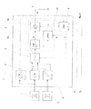
- Fig. 2 shows a functional block diagram of a pulse generator circuit arrangement 2 according to the invention in an IT system.
- the pulse generator 2 is connected via its system connections to the active conductors of an IT network 1 and via the ground connection to the ground line 3.
- a rectifier circuit 4 With a rectifier circuit 4, an AC voltage of the IT network 1 is first converted into a DC intermediate circuit voltage and then clocked by means of switching elements 5, so that it can serve as a pulse current-driving voltage source.
- an internal trigger signal tr 1 is supplied for clocking the switching elements 5 an internal trigger signal tr 1 is supplied.
- the pulse current I T is set dynamically by a circuit device 6 designed as a current control device 6, whereby a desired value specification dependent on the previously determined insulation resistance takes place with a current desired value w 1 as a variable reference variable.
- a circuit device 6 designed as a current control device 6, whereby a desired value specification dependent on the previously determined insulation resistance takes place with a current desired value w 1 as a variable reference variable.
- the size of the generated pulse current I T can be set so that a determination of the insulation resistance takes place simultaneously with the insulation fault location.
- the current control device 6 is functionally composed of a current measuring device 6a, an actuator 6b and a control logic 6c together.
- the pulse current I T driven by the clocked DC intermediate circuit voltage is determined by means of the current measuring device 6a and supplied as current actual value x to the actuator 6b and to the control logic 6c.
- the control logic 6c receives in addition to the actual current value x the internal current setpoint w 1 of a control and Ausncelogik 8 and calculated according to a control algorithm implemented a control signal y (manipulated variable).
- the control signal y is fed to the actuator 6b in order to change the actual current value x so that a desired pulse current I T is set at the output of the actuator 6b.
- test current pulses I T are detected by all measuring current transformers that are permanently installed in this circuit or arranged as portable measuring current transformers for insulation fault location.
- the predetermined by the control and Ausroulogik 8 internal current setpoint w 1 is dependent on one in the control and Ausroulogik. 8 certain insulation resistance value, for the calculation of which measured by a voltage measuring device 7 IT mains voltage and the determined by the control logic 8 manipulated variable y are used.
- control and Ausenselogik 8 as external signals set a system setpoint w 2 for the test current I T , from which the control and Ausenselogik 8 derives the internal current setpoint w 1 , including the insulation resistance, and a External system-wide trigger signal tr 2 as the basis for the internal trigger signal tr 1 for controlling the switching elements. 5
- the driving voltage can be obtained from a supplying network 9, to which a power supply unit 10 is coupled.
- the additional power supply 10 feeds a galvanically isolated DC voltage into the DC link, which drives the pulse current I T in the case of a voltage-free IT network 1.
- a pulse generator 2 is shown according to the prior art.
- This pulse generator essentially has the three functional blocks rectifier circuit 4, switching elements 5 and a circuit 6 designed as a simple current regulator 6. A dynamic adjustment of the pulse current I T in the sense of a closed loop is not provided.
Abstract
Description
Die Erfindung betrifft eine Pulsgenerator-Schaltungsanordnung zur Isolationsfehlersuche in IT-Netzen, mit einer Gleichrichterschaltung zur Umwandlung der IT-Netzspannung in einen DC-Zwischenkreis, Schaltgliedern mit einem Triggersignaleingang zur Auf- und Abschaltung einer DC-Zwischenkreisspannung und mit einer den Schaltgliedern nachgeordneten Schaltungseinrichtung zur Erzeugung eines in das IT-Netz einzuspeisenden Pulsstroms.The invention relates to a pulse generator circuit arrangement for insulation fault location in IT networks, with a rectifier circuit for converting the IT mains voltage in a DC link, switching elements with a trigger signal input for switching on and off a DC link voltage and a switching elements downstream circuit device for Generation of a pulse current to be fed into the IT network.
Weiterhin betrifft die Erfindung ein Verfahren zur Erzeugung von Pulssignalen zur Isolationsfehlersuche in IT-Netzen, umfassend die Signalverarbeitungsschritte: Umwandlung einer IT-Netzspannung in einen DC-Zwischenkreis mittels einer Gleichrichterschaltung, getriggerte Auf- und Abschaltung einer DC-Zwischenkreisspannung durch Schaltglieder mit einem Triggersignaleingang und Erzeugung eines in das IT-Netz einzuspeisenden Pulsstroms.Furthermore, the invention relates to a method for generating pulse signals for insulation fault location in IT networks, comprising the signal processing steps: converting an IT mains voltage into a DC link by means of a rectifier circuit, triggered switching on and off a DC link voltage by switching elements with a trigger signal input and Generation of a pulse current to be fed into the IT network.
Um eine hohe Verfügbarkeit und Betriebssicherheit der elektrischen Stromversorgung sicherzustellen sowie die Personensicherheit im Bereich elektrischer Anlagen zu gewährleisten, kommen in zunehmendem Maße Stromversorgungsnetze zum Einsatz, deren aktive Teile von dem Erdpotential getrennt sind. Bei dieser als ungeerdetes IT-System bezeichneten Art des Stromversorgungsnetzes kann ein aktiver Leiter einen Isolationsfehler aufweisen, ohne dass der laufende Betrieb der Anlage unterbrochen werden muss, weil sich wegen des im Idealfall unendlich großen Impedanzwertes zwischen Leiter und Erde in diesem ersten Fehlerfall kein geschlossener Stromkreis ausbilden kann. Als Isolationsfehler wird dabei ein fehlerhafter Zustand des IT-Systems, insbesondere ein Körper- oder Erdschluss, also eine leitende Verbindung inaktiver Anlagenteile mit leitenden Betriebsmitteln oder eine leitende Verbindung eines aktiven Leiters gegen Erde, verstanden.To ensure a high level of availability and reliability of the electrical power supply as well as personal safety in the area To ensure electrical systems, increasingly power supply networks are used, the active parts are separated from the ground potential. In this type of power supply system, referred to as an ungrounded IT system, an active conductor may have an insulation fault without interrupting the ongoing operation of the system because, because of the ideally infinite impedance value between the conductor and ground, in this first fault case no closed circuit can train. In this case, an insulation fault is understood to mean a faulty state of the IT system, in particular a physical or ground fault, that is to say a conductive connection of inactive system components with conductive equipment or a conductive connection of an active conductor to ground.
Aus dieser Betrachtung geht hervor, dass der Widerstand in dem zu überwachenden Netz, einschließlich der Widerstände aller daran angeschlossenen Betriebsmittel gegen Erde (Isolationswiderstand) ständig überwacht werden muss, da durch einen möglichen weiteren Fehler an einem anderen aktiven Leiter (zweiter Fehler) eine Fehlerschleife entstünde und der darin fließende Fehlerstrom in Verbindung mit einer Überstrom-Schutzeinrichtung eine Abschaltung der Anlage zur Folge hätte. Mit einer ständigen Isolationsüberwachung des ungeerdeten IT-Systems kann ein Absinken des Isolationswiderstands rechtzeitig erkannt und gemeldet werden.It can be seen from this observation that the resistance in the network to be monitored, including the resistances of all equipment connected to earth (insulation resistance), must be constantly monitored, since a potential error on another active conductor (second error) would result in a fault loop and the residual current flowing therein in connection with an overcurrent protection device would result in a shutdown of the system. With permanent insulation monitoring of the unearthed IT system, a reduction in the insulation resistance can be detected and reported in good time.
Dem Stand der Technik gemäß beruhen die Messverfahren zur Bestimmung des Isolationswiderstandes prinzipiell auf der Überlagerung einer in einem Isolationsüberwachungsgerät erzeugten Messspannung zwischen den Leitern des IT-Netzes und Erde, so dass sich ein bestimmter, dem Isolationsfehler proportionaler Messstrom einstellt, der an einem Messwiderstand des Isolationsüberwachungsgerätes einen entsprechenden Spannungsabfall hervorruft. Überschreitet der Spannungsabfall infolge eines abgesunkenen Isolationswiderstands und damit eines höheren Messstroms einen bestimmten Wert, so wird eine Meldung ausgelöst. Um im Hinblick auf eine zuverlässige Isolationsüberwachung in heutigen modernen Netzen, in denen eine Vielzahl von Betriebsmitteln mit elektronischen Bauelementen versehen ist, Messverfälschungen entgegenzuwirken, hervorgerufen beispielsweise durch von Umrichtern erzeugte Gleichstromkomponenten, sind die Messverfahren stets weiter entwickelt worden. In reinen Wechselstromnetzen ohne verfälschende Gleichspannungsanteile kann das Verfahren der Überlagerung einer Messgleichspannung eingesetzt werden, wohingegen in störungsbehafteten Umgebungen eine gesteuerte, speziell getaktete Messspannung zum Treiben von Pulssignalen zur Anwendung gelangt.According to the state of the art, the measuring methods for determining the insulation resistance are based in principle on the superimposition of a measuring voltage generated in an insulation monitoring device between the conductors of the IT network and ground, so that a specific measurement current proportional to the insulation fault is established at a measuring resistor of the insulation monitoring device causes a corresponding voltage drop. If the voltage drop due to a reduced insulation resistance and thus a higher measuring current exceeds a certain value, a message is triggered. Around in view of reliable insulation monitoring in today's modern networks, in which a variety of resources is provided with electronic components to counteract Messverfälschungen, caused for example by DC-generated by DC converters, the measurement methods have always been developed. In pure AC networks without distorting DC components, the method of superimposing a DC measurement voltage can be used, whereas in noisy environments a controlled, specially clocked measurement voltage for driving pulse signals is used.
Ist ein Absinken des Isolationswiderstandes erkannt, startet die Isolationsfehlersuche indem das Isolationsüberwachungsgerät oder ein separates Prüfgerät einen Prüfstrom erzeugt und in das IT-Netz einspeist. Um Isolationsfehler in einem DC-Netz zuverlässig erkennen zu können und auf Grund der verfügbaren Messtechnik besitzt auch der zur Isolationsfehlersuche eingespeiste Prüfstrom vorzugsweise einen impulsförmigen Verlauf mit alternierender Polarität (Pulsstrom), so dass abwechselnd beide Leiter (L+ und L-) vom Prüfstrom durchflossen werden. Dieses Prüfstromsignal wird von allen Messstromwandlern, die im fehlerbehafteten Leitungsabgang des Netzes liegen, erfasst und durch ein Isolationsfehler-Auswertegerät ausgewertet und angezeigt. Durch die Zuordnung Messstromwandler/Stromkreis bzw. Leitungsabgang kann der Fehlerort lokalisiert werden.If a drop in the insulation resistance is detected, the insulation fault search starts by the insulation monitoring device or a separate test device generating a test current and feeding it into the IT network. In order to be able to reliably detect insulation faults in a DC network and, on the basis of the available measurement technique, the test current fed in for insulation fault finding preferably also has a pulse-shaped course with alternating polarity (pulse current) so that the test current alternately flows through both conductors (L + and L-) , This test current signal is detected by all measuring current transformers that are in the faulty cable outlet of the network and evaluated and displayed by an insulation fault evaluation device. By assigning the measuring current transformer / circuit or line output, the fault location can be localized.
Als nachteilig erweist sich bei dieser nach dem Stand der Technik üblichen Vorgehensweise, dass die Bestimmung des Isolationswiderstands und die Lokalisierung von Isolationsfehlern zwei getrennte, in sich abgeschlossene Prozesse darstellen. Dies hat zur Folge, dass beispielsweise zur Durchführung einer erneuten Messung des Isolationswiderstands während der bereits eingeleiteten Fehlersuche die Einspeisung der Prüfimpulse unterbrochen werden muss, um mit einer geeigneten Messspannung die Isolationswiderstandsmessung durchführen zu können. Eine zeitgleiche Bestimmung des Isolationswiderstands während der Fehlersuche ist somit nicht in einfacher Weise möglich.A disadvantage of this approach, which is conventional in the prior art, is that the determination of the insulation resistance and the location of insulation faults represent two separate, self-contained processes. This has the consequence that, for example, to carry out a new measurement of the insulation resistance during the already initiated troubleshooting the feed of the test pulses must be interrupted in order to perform the insulation resistance measurement with a suitable measuring voltage can. A simultaneous determination of the insulation resistance during troubleshooting is therefore not possible in a simple manner.
Des Weiteren bieten zwar Geräte nach dem Stand der Technik die Möglichkeit, bei der Fehlersuche den Prüfstrom durch entsprechende Schaltungseinrichtungen wie Stromregler während der Impulsdauer zu stabilisieren und auf einen oder mehrere Maximalwerte zu begrenzen, aber diese Einstellungen stellen nur eine relativ grobe Anpassung des Pulsstromes an die Netzverhältnisse dar, so dass oftmals ein unnötig hoher Pulsstrom generiert wird. Dabei kann es in der Generatorschaltung zu einer übermäßigen Wärmeentwicklung kommen, der bislang durch die Verwendung von großflächigen Kühlkörpern oder Übertemperaturabschaltungen begegnet wurde. In nachteiliger Weise führen diese Gegenmaßnahmen damit direkt oder indirekt über Betriebsunterbrechungen zu Kostensteigerungen.Furthermore, although devices of the prior art offer the possibility of stabilizing the test current through corresponding circuit devices such as current regulators during the pulse duration and limiting them to one or more maximum values, these settings provide only a relatively rough adaptation of the pulse current to the Network conditions, so that often an unnecessarily high pulse current is generated. This can lead to excessive heat generation in the generator circuit, which has hitherto been counteracted by the use of large-area heat sinks or overtemperature shutdowns. Disadvantageously, these countermeasures lead directly or indirectly to business interruptions to cost increases.
Darüber hinaus steht in abgeschalteten zu untersuchenden IT-Systemen eine den Pulsstrom treibende Spannung nicht zur Verfügung. Hier stellt sich also grundsätzlich das Problem einer geeigneten Spannungsversorgung zur Erzeugung des Prüfstroms.In addition, a voltage driving the pulse current is not available in switched-off IT systems to be examined. In principle, this poses the problem of a suitable voltage supply for generating the test current.
Der vorliegenden Erfindung liegt somit die Aufgabe zu Grunde, eine Pulsgenerator-Schaltungsanordnung und ein Verfahren zur Erzeugung von Pulssignalen zur Isolationsfehlersuche in IT-Netzen zu entwickeln, die den Prozess einer mit der Isolationsüberwachung verbundenen Isolationsfehlersuche vereinfachen und auch in abgeschalteten IT-Netzen verwendbar bzw. anwendbar sind.The present invention is therefore based on the object to develop a pulse generator circuit arrangement and a method for generating pulse signals for insulation fault location in IT networks, which simplify the process of insulation fault detection associated with insulation monitoring and can also be used in disconnected IT networks or are applicable.
Diese Aufgabe wird bezogen auf eine Schaltungsanordnung in Verbindung mit dem Oberbegriff des Anspruchs 1 gelöst durch eine Steuer- und Auswertelogik zur Bestimmung des Isolationswiderstands des IT-Netzes und durch eine Schaltungseinrichtung zur Erzeugung des Pulsstroms, die als Stromregelungseinrichtung ausgeführt ist, die eine dynamische Einstellung des Pulsstromes in Abhängigkeit des ermittelten Isolationswiderstandes ermöglicht.This object is achieved on the basis of a circuit arrangement in conjunction with the preamble of
Erfindungsgemäß ist in die Pulsgenerator-Schaltungsanordnung eine Steuer- und Auswertelogik integriert, die in der Lage ist, den Isolationswiderstand eines angeschlossenen IT-Netzes während der Erzeugung eines Pulsstroms zu bestimmen. Damit ergibt sich in vorteilhafter Weise die Möglichkeit, mit der Pulsgenerator-Schaltungsanordnung zeitgleich mit der Fehlersuche auch eine Isolationswiderstandsbestimmung durchführen zu können. Es ist nicht erforderlich, während der Fehlersuche die Pulssequenz zu unterbrechen, um eine Isolationswiderstandsmessung ausführen zu können.According to the invention, a control and evaluation logic is integrated in the pulse generator circuit arrangement, which is able to determine the insulation resistance of a connected IT network during the generation of a pulse current. This advantageously results in the possibility of being able to carry out an insulation resistance determination at the same time as troubleshooting with the pulse generator circuit arrangement. It is not necessary to interrupt the pulse sequence during troubleshooting in order to perform an insulation resistance measurement.
Ausgangspunkt der vorliegenden Erfindung ist die grundsätzliche Betrachtung, dass bei einem Isolationsfehler ein Prüfstrom IT (Pulsstrom) in einem Stromkreis fließt, der als Quellenspannung U0 die IT-Netzspannung bzw. eine daraus abgeleitete DC-Zwischenkreisspannung besitzt und dessen elektrischer Widerstand sich aus der Reihenschaltung eines Isolationsfehlerwiderstands RF (Isolationswiderstand im Fehlerfall) und eines veränderlichen Innenwiderstands RPG des Pulsgenerators ergibt. Soll nun ein vorgegebener, innerhalb einer Impulsdauer konstanter Prüfstrom IT fließen, so stellt sich bei der bekannten DC-Zwischenkreisspannung U0 ein bestimmter Wert des Innenwiderstands RPG des Pulsgenerators ein. Der Innenwiderstand RPG des Pulsgenerators ist intern bestimmbar, so dass sich nach dem ohmschen Gesetz und den in linearen Netzen geltenden Strom-Spannungsbeziehungen der Isolationsfehlerwiderstand RF berechnen lässt aus: RF = (U0/IT) - RPG. Um einen - innerhalb der Impulsdauer in eingeschwungenem Zustand - konstanten Pulsstrom zu erzeugen, ist die Schaltungseinrichtung zur Erzeugung des Pulsstroms als Stromregelungseinrichtung ausgeführt, die unter Einbeziehung des ermittelten Isolationswiderstandswertes eine dynamische Einstellung des Pulsstromes gestattet. Durch diese adaptive Einstellung kann der Pulsstrom an den durch den ermittelten Isolationswiderstand repräsentierten elektrischen Zustand des zu untersuchenden Netzes angepasst werden. Einerseits bewegt sich der Pulsstrom damit in einem Bereich, in dem der Isolationswiderstand exakt ermittelt werden kann, zum anderen ergibt sich automatisch auch eine an die Netzverhältnisse angepasste Einstellung des Pulsstromes.The starting point of the present invention is the fundamental consideration that in an insulation fault, a test current I T (pulse current) flows in a circuit which has as source voltage U 0 the IT mains voltage or a DC link voltage derived therefrom and whose electrical resistance is derived from the Series connection of an insulation fault resistance R F (insulation resistance in case of failure) and a variable internal resistance R PG of the pulse generator results. If now a predetermined, within a pulse duration constant test current I T flow, so sets in the known DC link voltage U 0 a certain value of the internal resistance R PG of the pulse generator. The internal resistance R PG of the pulse generator can be determined internally, so that according to Ohm's law and the current-voltage relationships applicable in linear networks, the insulation fault resistance R F can be calculated from: R F = (U 0 / I T ) -R PG . In order to generate a constant pulse current within the pulse duration in the steady state, the circuit device for generating the pulse current is designed as a current control device which, taking into account the determined insulation resistance value, permits a dynamic adjustment of the pulse current. By means of this adaptive adjustment, the pulse current can be connected to the electrical state of the network to be examined, which is represented by the determined insulation resistance be adjusted. On the one hand, the pulse current thus moves in a range in which the insulation resistance can be determined exactly, on the other hand automatically results in an adapted to the network conditions setting the pulse current.
In vorteilhafter Ausgestaltung weist die Stromregelungseinrichtung zur dynamischen Einstellung des Pulsstromes daher eine Regellogik auf, die eingangsseitig mit einer Strommesseinrichtung zur Ermittlung eines Strom-Istwertes des IT-Netzes sowie zur Einbeziehung eines von dem Isolationswiderstand abhängigen Strom-Sollwertes mit der Steuer- und Auswertelogik verbunden ist und die ausgangseitig eine Stellgröße bereitstellt, die über ein Stellglied den Strom-Istwert verändert, so dass sich am Ausgang des Stellgliedes ein angepasster Ausgangsstromwert einstellt.In an advantageous embodiment, the current control device for dynamic adjustment of the pulse current therefore has a control logic which is connected on the input side with a current measuring device for determining a current actual value of the IT network and to include a dependent of the insulation resistance current setpoint with the control and evaluation logic and the output side provides a manipulated variable that changes the actual current value via an actuator, so that adjusts an adapted output current value at the output of the actuator.
Nach den vorangegangenen Überlegungen ist der Isolationswiderstand prinzipiell mit einem beliebigen konstanten Prüf-/Pulsstrom ermittelbar. Folgende praktische Erwägungen jedoch führen zu der Notwendigkeit, den Prüfstrom verändern zu können: Erstens ist der Messbereich begrenzt durch den minimal erreichbaren Innenwiderstand RPG des Pulsgenerators sowie durch die zur Verfügung stehende Quellenspannung U0. Zweitens muss je nach Schaltungskonzept eine (zu) hohe thermische Verlustleistung abgeführt werden. Drittens ergäben sich bei nichtlinearem Verhalten Arbeitsbereiche des Stellgliedes mit hoher Empfindlichkeit und mit geringer Empfindlichkeit gegenüber der Stellgröße, wobei in Bereichen mit niedriger Empfindlichkeit der Innenwiderstand RPG des Pulsgenerators besonders genau ermittelt werden kann.After the foregoing considerations, the insulation resistance can be determined in principle with any constant test / pulse current. However, the following practical considerations lead to the need to be able to change the test current: First, the measuring range is limited by the minimum achievable internal resistance R PG of the pulse generator and by the available source voltage U 0 . Second, depending on the circuit concept, a (too) high thermal power loss must be dissipated. Third, in non-linear behavior, actuator operating ranges would be high in sensitivity and low in sensitivity to the manipulated variable, and in low sensitivity regions, the internal resistance R PG of the pulse generator could be more accurately determined.
Die Regellogik berechnet somit auf der Basis eines von einer Strommesseinrichtung ermittelten Strom-Istwertes des IT-Netzes und einem von der Steuer- und Auswertelogik zugeführten, von dem ermittelten Isolationswiderstand abgeleiteten Strom-Sollwert zunächst eine Stellgröße. Diese Stellgröße wirkt über ein Stellglied, dem ebenfalls der in der Strommesseinrichtung ermittelte Strom-Istwert des IT-Netzes zugeführt wird, auf den Strom-Istwert ein, so dass ein entsprechend der Regellogik veränderter Ausgangsstrom generiert wird.The control logic thus first calculates a manipulated variable on the basis of a current actual value of the IT network determined by a current measuring device and a current desired value derived from the control and evaluation logic derived from the determined insulation resistance. This manipulated variable acts via an actuator, which also supplied to the determined in the current measuring device current actual value of the IT network is, on the current actual value, so that a modified according to the control logic output current is generated.
Weiterhin ist die Steuer- und Auswertelogik zur Bestimmung des ohmschen Anteils des Isolationswiderstands eingangsseitig mit dem Stellgrößenausgang der Regellogik und mit einer Spannungsmesseinrichtung zur Messung der IT-Netzspannung verbunden und gibt ausgangsseitig einen Strom-Sollwert an die Regellogik und ein internes Triggersignal an die Schaltglieder zur Auf- und Abschaltung der DC-Zwischenkreisspannung weiter.Furthermore, the control and evaluation logic for determining the resistive component of the insulation resistance is connected on the input side to the manipulated variable output of the control logic and to a voltage measuring device for measuring the IT mains voltage and outputs on the output side a current setpoint to the control logic and an internal trigger signal to the switching elements - And switching off the DC link voltage on.
Die Pulsgenerator-Schaltungsanordnung umfasst mit Vorteil eine Spannungsmesseinrichtung zur Ermittlung der Netzspannung des IT-Systems. Aus dieser Netzspannung und der von der Regellogik zugeführten Stellgröße kann die Steuer- und Auswertelogik den ohmschen Anteil des Isolationswiderstandes bestimmen. Eine von diesem ohmschen Anteil abgeleitete Größe wird als variabler Strom-Sollwert der Regellogik zugeführt und dient damit als Führungsgröße der Stromregelungseinrichtung.The pulse generator circuit arrangement advantageously comprises a voltage measuring device for determining the mains voltage of the IT system. From this mains voltage and the manipulated variable supplied by the control logic, the control and evaluation logic can determine the ohmic component of the insulation resistance. A derived from this ohmic component size is supplied as a variable current setpoint of the control logic and thus serves as a reference variable of the current control device.
Bevorzugt weist die Steuer- und Auswertelogik weitere Eingänge für einen extern zugeführten System-Sollwert des Pulsstromes und für ein extern zugeführtes systemweites Triggersignal für die Pulsstromsequenz auf.The control and evaluation logic preferably has further inputs for an externally supplied system setpoint value of the pulse stream and for an externally supplied system-wide trigger signal for the pulse stream sequence.
Damit können der Pulsgenerator-Schaltungsanordnung von außen ein System-Sollwert des Pulsstromes sowie ein systemweites Triggersignal für die Pulsstromsequenz vorgegeben und bei der Berechnung des Strom-sollwertes für die Regellogik sowie bei der Ableitung des internen Triggersignals berücksichtigt werden.Thus, the pulse generator circuit arrangement can be preset from the outside a system setpoint of the pulse stream and a system-wide trigger signal for the pulse stream sequence and taken into account in the calculation of the current setpoint for the control logic and in the derivation of the internal trigger signal.
Vorzugsweise weist die Pulsgenerator-Schaltungsanordnung ein zusätzliches Netzteil auf, das mittels einer externen Versorgungsspannung aus einem weiteren Stromversorgungsnetz eine galvanisch getrennte DC-Spannung in den DC-Zwischenkreis einspeist. Damit ist die Möglichkeit geschaffen, auch bei abgeschalteten IT-Systemen einen (Prüf-)Strom generieren und eine Fehlersuche durchführen zu können.Preferably, the pulse generator circuit arrangement has an additional power supply, which by means of an external supply voltage from a further power supply network, a galvanically isolated DC voltage fed into the DC link. This creates the opportunity to generate (test) power even when the IT systems are switched off and to be able to carry out troubleshooting.
Die der Erfindung zu Grunde liegende Aufgabe wird bezogen auf ein Verfahren in Verbindung mit dem Oberbegriff des Anspruchs 6 weiterhin gelöst durch eine Bestimmung des Isolationswiderstands des IT-Netzes mittels einer Steuer- und Auswertelogik und durch die Erzeugung des in das IT-Netz eingespeisten Pulsstroms mittels einer Stromregelungseinrichtung derart, dass eine dynamische Einstellung des Pulsstromes in Abhängigkeit des ermittelten Isolationswiderstandes erfolgt.The object of the invention is further based on a method in conjunction with the preamble of
Korrespondierend zu den Vorrichtungsmerkmalen der erfindungsgemäßen Pulsgenerator-Schaltungsanordnung umfasst das beanspruchte Verfahren in einem erfindungsgemäßen Verfahrensschritt eine Bestimmung des Isolationswiderstands, die zeitgleich mit einer Isolationsfehlersuche erfolgt. Weiterhin wird erfindungsgemäß der eingespeiste Pulsstrom dynamisch unter mittelbarer Einbeziehung des Isolationswiderstands über die Variation des Strom-Sollwertes eingestellt. Die parallel verlaufende Durchführung von Isolationswiderstandsmessung und Isolationsfehlersuche bietet den Vorteil, dass in einfacher Weise während der Isolationsfehlersuche der Isolationswiderstand wiederholt geprüft werden kann und der so ermittelte Wert des Isolationswiderstandes zur Regelung des einzuspeisenden Pulsstroms herangezogen werden kann.Corresponding to the device features of the pulse generator circuit arrangement according to the invention, the method claimed in a method step according to the invention comprises a determination of the insulation resistance, which takes place at the same time as an insulation fault location. Furthermore, according to the invention, the injected pulse current is set dynamically with indirect inclusion of the insulation resistance via the variation of the current setpoint. The parallel implementation of insulation resistance measurement and insulation fault location offers the advantage that the isolation resistance can be repeatedly tested in a simple manner during the isolation fault search and the value of the insulation resistance determined in this way can be used to regulate the pulse current to be injected.
Daher erfolgt in einer bevorzugten Ausgestaltung die Stromregelung zur dynamischen Einstellung des Pulsstromes durch eine Regellogik, die aus einem von einer Strommesseinrichtung zugeführten Strom-Istwert des IT-Netzes und einem von der Steuer- und Auswertelogik zugeführten Isolationswiderstands-abhängigen Strom-Sollwert eine Stellgröße berechnet, die über ein Stellglied den Strom-Istwert verändert, so dass sich am Ausgang des Stellgliedes ein angepasster Ausgangsstromwert einstellt.Therefore, in a preferred embodiment, the current control for dynamic adjustment of the pulse current is calculated by a control logic which calculates a manipulated variable from a current actual value of the IT network supplied by a current measuring device and an insulation resistance-dependent current setpoint supplied by the control and evaluation logic. which via an actuator changes the current actual value, so that adjusts an adjusted output current value at the output of the actuator.
Zunächst wird daher mittels einer Strommesseinrichtung der tatsächlich in dem zu untersuchenden IT-Netz fließende Strom ermittelt und als Strom-Istwert einer Regellogik sowie einem Stellglied zugeführt. Als Soll-Größe erhält die Regellogik von der Steuer- und Auswertelogik einen Isolationswiderstands-abhängigen Strom-Sollwert vorgegeben. Aus diesen beiden Eingangsgrößen berechnet die Regellogik entsprechend dem implementierten Reglerverhalten eine Stellgröße, auf deren Basis ein Prüfstrom vorgegeben wird, bei beim der Isolationswiderstand möglichst exakt berechnet werden kann. Die Stellgröße verändert über das Stellglied den Strom-Istwert, so dass sich der gewünschte, dynamisch angepasste Ausgangsstromwert einstellt. Beispielsweise könnte die Strategie verfolgt werden, den Pulsstrom so einzustellen, dass sich eine Stellgröße/ein Stellgrößenfaktor von etwa 50% ergibt. Bei Änderungen des Isolationswiderstandswertes stünde dann noch genügende Spielraum zur Verfügung, um nicht den Prüfstrom sofort wieder neu anpassen zu müssen.First of all, therefore, the current actually flowing in the IT network to be examined is determined by means of a current measuring device and supplied as a current actual value to a control logic as well as to an actuator. As a set value, the control logic receives an insulation resistance-dependent current setpoint from the control and evaluation logic. From these two input variables, the control logic computes a manipulated variable according to the implemented controller behavior, on the basis of which a test current is specified, at which the insulation resistance can be calculated as exactly as possible. The manipulated variable changes the actual current value via the actuator so that the desired, dynamically adjusted output current value is set. For example, the strategy could be followed to set the pulse current so that a manipulated variable / a manipulated variable factor of about 50% results. With changes in the insulation resistance value, there would then still be sufficient leeway to avoid having to readjust the test current immediately.
Vorzugsweise werden zur Bestimmung des ohmschen Anteils des Isolationswiderstandes in der Steuer- und Auswertelogik als Eingangsgrößen die von der Regellogik gelieferte Stellgröße und die von der Spannungsmesseinrichtung bereitgestellte IT-Netzspannung herangezogen, wobei die Steuer- und Auswertelogik den in Abhängigkeit des ermittelten Isolationswiderstands veränderlichen Strom-Sollwert an die Regellogik weitergibt. Die zeitgleich zur Pulsstrom-Einspeisung ausgeführte Bestimmung des ohmschen Anteils des Isolationswiderstandes erfolgt aus einer Spannungs-/Strommessung wobei die IT-Netzspannung von einer unmittelbar an das IT-Netz angeschlossenen Spannungsmesseinrichtung ermittelt wird. Der benötigte Stromwert wird durch die von der Regellogik gelieferte Stellgröße abgebildet.Preferably, to determine the ohmic portion of the insulation resistance in the control and Auswertelogik as input variables supplied by the control logic manipulated variable and provided by the voltage measuring IT network voltage is used, the control and Auswertelogik varying depending on the determined insulation resistance current setpoint to the rule logic. The determination of the ohmic portion of the insulation resistance carried out at the same time as the pulse current feed takes place from a voltage / current measurement, the IT mains voltage being determined by a voltage measuring device connected directly to the IT network. The required current value is represented by the manipulated variable delivered by the control logic.
Vorzugsweise erfolgt die dynamische Einstellung des Pulsstromes nach einem oder mehreren der Kriterien a) Optimierung des Arbeitsbereichs des Stellgliedes, b) Stellgröße in einem Bereich, der eine möglichst genaue Bestimmung des Isolationswiderstandes erlaubt, c) Minimierung der Verlustleistung des Stellgliedes.Preferably, the dynamic adjustment of the pulse current is carried out according to one or more of the criteria a) optimization of the working range of the actuator, b) manipulated variable in a range of one possible accurate determination of the insulation resistance allowed, c) minimization of the power loss of the actuator.
Das Regelverhalten kann somit daraufhin ausgelegt werden, dass das Stellglied in einem optimalen Arbeitsbereich arbeitet, also nicht an den Grenzen seiner Einstellbereiche angesteuert wird und/oder die Regelung kann so ausgelegt sein, dass die Verlustleistung des Stellgliedes minimiert wird. Daneben ist auch eine Einstellung des Pulsstromes derart möglich, dass sich die Stellgröße in einem Bereich bewegt, der eine möglichst genaue Bestimmung des Isolationswiderstands erlaubt, in dem somit die Messungenauigkeiten minimal sind.The control behavior can thus be interpreted as meaning that the actuator operates in an optimal operating range, ie is not driven at the limits of its setting ranges and / or the control can be designed so that the power loss of the actuator is minimized. In addition, an adjustment of the pulse current is possible in such a way that the manipulated variable moves in a range which allows the most accurate possible determination of the insulation resistance, in which thus the measurement inaccuracies are minimal.
Bevorzugt weist der Pulsstrom einen impulsförmigen, alternierenden Verlauf auf. Die bisher verfügbare und eingesetzte Messtechnik zur Isolationsfehlersuche kann einen impulsförmigen Verlauf des Pulsstromes notwendig machen. Zudem ist es zweckmäßig, dass die Impulse eine alternierende Polarität aufweisen, damit beide Leiter eines IT-Netzes vom Prüfstrom durchflossen werden.Preferably, the pulse current has a pulse-shaped, alternating course. The previously available and used measurement technique for insulation fault location can make a pulse-shaped course of the pulse current necessary. In addition, it is expedient that the pulses have an alternating polarity, so that both conductors of an IT network are traversed by the test current.
Um in abgeschalteten IT-Systemen - wenn eine den (Puls-)Strom treibende Netzspannungsquelle nicht zur Verfügung steht - dennoch eine Fehlersuche durchführen zu können, ist vorgesehen, eine galvanisch getrennte DC-Spannung mittels einer externen Versorgungsspannung aus einem weiteren Stromversorgungsnetz in den DC-Zwischenkreis einzuspeisen.In order to be able to carry out fault finding in disconnected IT systems - if a mains voltage source driving the (pulse) current is not available, it is provided that a galvanically separated DC voltage is fed from an additional power supply network into the DC power supply via an external supply voltage. Feed in DC link.
Weitere vorteilhafte Ausgestaltungsmerkmale ergeben sich aus der nachfolgenden Beschreibung und den Zeichnungen, die eine bevorzugte Ausführungsform der Erfindung an Hand eines Beispiels erläutern. Es zeigen:
- Fig. 1:
- ein Ersatzschaltbild eines Prüfstromkreises,
- Fig. 2:
- ein funktionales Blockschaltbild einer erfindungsgemäßen Pulsgenerator-Schaltungsanordnung,
- Fig. 3:
- einen Pulsgenerator nach dem Stand der Technik.
- Fig. 1:
- an equivalent circuit of a test circuit,
- Fig. 2:
- a functional block diagram of a pulse generator circuit arrangement according to the invention,
- 3:
- a pulse generator according to the prior art.
Der Pulsstrom IT wird durch eine als Stromregelungseinrichtung 6 ausgeführte Schaltungseinrichtung 6 dynamisch eingestellt, wobei eine von dem zuvor bestimmten Isolationswiderstand abhängige SollwertVorgabe mit einem Strom-Sollwert w1 als variable Führungsgröße erfolgt. Mit dieser adaptiven Regelung kann die Größe des erzeugten Pulsstromes IT so eingestellt werden, dass gleichzeitig mit der Isolationsfehlersuche eine Bestimmung des Isolationswiderstands erfolgt.The pulse current I T is set dynamically by a
Die Stromregelungseinrichtung 6 setzt sich funktional aus einer Strommesseinrichtung 6a, einem Stellglied 6b und einer Regellogik 6c zusammen. Dabei wird der durch die getaktete DC-Zwischenkreisspannung getriebene Pulsstrom IT mittels der Strommesseinrichtung 6a bestimmt und als Strom-Istwert x dem Stellglied 6b sowie der Regellogik 6c zugeführt. Die Regellogik 6c empfängt neben dem Strom-Istwert x den internen Strom-Sollwert w1 von einer Steuer- und Auswertelogik 8 und berechnet entsprechend einem implementierten Regelalgorithmus ein Stellsignal y (Stellgröße). Das Stellsignal y wird dem Stellglied 6b zugeleitet, um den Strom-Istwert x so zu verändern, dass sich ein gewünschter Pulsstrom IT am Ausgang des Stellgliedes 6b einstellt.The
Wie aus oben dargestelltem Sachverhalt zur Bestimmung des Isolationswiderstands hervorgeht, ist der Innenwiderstand RPG des Pulsgenerators variabel und wird in erster Linie bestimmt durch den Widerstand des Stellgliedes 6b. Dieser ergibt sich durch seine Ansteuerung mittels der Stellgröße y, wobei hier vereinfachend ein linearer Zusammenhang angenommen sei. Bei einer großen Stellgröße y ergibt sich in eingeschwungenem Zustand der Regelung ein großer elektrischer Leitwert, da das Stellglied 6b gut leitet. Dagegen stellt sich bei einer kleinen Stellgröße y ein kleiner Leitwert ein, da das Stellglied 6b sperrt. Der (Innen)Leitwert GPG ist somit durch einen von der Stellgröße y gebildeten Faktor einstellbar: GPG = Faktor*Soll-Leitwert. Damit ist auch der Innenwiderstand RPG des Pulsgenerators bekannt: RPG = 1/(Faktor*Soll-Leitwert).As is apparent from the above-described fact for the determination of the insulation resistance, the internal resistance R PG of the pulse generator is variable and is determined primarily by the resistance of the
Es fließt somit in dem (Prüf-)Stromkreis ein voreinstellbarer Pulsstrom IT, der von dem Pulsgenerator 2 über die Erdleitung 3, den Isolationsfehler und die Leitungen des IT-Netzes 1 zurück in den Pulsgenerator 2 fließt. Die Prüfstromimpulse IT werden von allen Messstromwandlern erfasst, die in diesem Stromkreis fest installiert oder als portable Messstromwandler zur Isolationsfehlersuche angeordnet sind.It thus flows in the (test) circuit, a presettable pulse current I T , which flows from the
Der von der Steuer- und Auswertelogik 8 vorgegebene interne Strom-Sollwert w1 ist abhängig von einem in der Steuer- und Auswertelogik 8 bestimmten Isolationswiderstandswert, zu dessen Berechnung die mittels einer Spannungsmesseinrichtung 7 gemessene IT-Netzspannung und die von der Regellogik 8 ermittelte Stellgröße y herangezogen werden.The predetermined by the control and
In dem dargestellten Ausführungsbeispiel werden der Steuer- und Auswertelogik 8 als externe Signale ein System-Sollwert w2 für den Prüfstrom IT vorgegeben, aus dem die Steuer- und Auswertelogik 8 unter Einbeziehung des Isolationswiderstandes den internen Strom-Sollwert w1 ableitet, sowie ein externes systemweites Triggersignal tr2 als Basis für das interne Triggersignal tr1 zur Ansteuerung der Schaltglieder 5.In the illustrated embodiment, the control and
Befindet sich das zu untersuchende Netz 1 in abgeschaltetem Zustand, so kann die treibende Spannung aus einem versorgenden Netz 9 bezogen werden, an das ein Netzteil 10 angekoppelt ist. Das zusätzliche Netzteil 10 speist eine galvanisch getrennte DC-Spannung in den DC-Zwischenkreis ein, die im Fall eines spannungslosen IT-Netzes 1 den Pulsstrom IT treibt.If the
In
Claims (11)
gekennzeichnet durch
eine Steuer- und Auswertelogik zur Bestimmung des Isolationswiderstands des IT-Netzes und durch eine Schaltungseinrichtung zur Erzeugung des Pulsstroms, die als Stromregelungseinrichtung ausgeführt ist, die eine dynamische Einstellung des Pulsstromes in Abhängigkeit des ermittelten Isolationswiderstandes ermöglicht.Pulse generator circuit arrangement for insulation fault location in IT networks, with a rectifier circuit for converting the IT grid voltage in a DC link, switching elements with a trigger signal input for switching on and off a DC link voltage and with a switching elements downstream circuit means for generating a in the IT network to be fed with pulse current,
marked by
a control and evaluation logic for determining the insulation resistance of the IT network and by a circuit device for generating the pulse current, which is designed as a current control device that allows dynamic adjustment of the pulse current as a function of the determined insulation resistance.
dadurch gekennzeichnet,
dass die Stromregelungseinrichtung zur dynamischen Einstellung des Pulsstromes eine Regellogik aufweist, die eingangsseitig mit einer Strommesseinrichtung zur Ermittlung eines Strom-Istwertes des IT-Netzes sowie zur Einbeziehung eines von dem Isolationswiderstand abgeleiteten Strom-Sollwertes mit der Steuer- und Auswertelogik verbunden ist und die ausgangseitig eine Stellgröße bereitstellt, die über ein Stellglied den Strom-Istwert verändert, so dass sich am Ausgang des Stellgliedes ein angepasster Ausgangsstromwert einstellt.Circuit arrangement according to Claim 1,
characterized,
in that the current regulation device has a control logic for the dynamic adjustment of the pulse current, the input side having a current measuring device for determining a current actual value of the IT network and for incorporating one of the insulation resistance derived current setpoint is connected to the control and Auswertelogik and the output side provides a control variable that changes the current value via an actuator, so that adjusts an adjusted output current value at the output of the actuator.
dadurch gekennzeichnet,
dass die Steuer- und Auswertelogik zur Bestimmung des ohmschen Anteils des Isolationswiderstands eingangsseitig mit dem Stellgrößenausgang der Regellogik und mit einer Spannungsmesseinrichtung zur Messung der IT-Netzspannung verbunden ist und ausgangsseitig einen Strom-Sollwert an die Regellogik und ein internes Triggersignal an die Schaltglieder zur Auf- und Abschaltung der DC-Zwischenkreisspannung weitergibt.Circuit arrangement according to Claim 1 or 2,
characterized,
that the control and evaluation logic for determining the resistive component of the insulation resistance is connected on the input side to the manipulated variable output of the control logic and to a voltage measuring device for measuring the IT mains voltage and on the output side to a current setpoint to the control logic and an internal trigger signal to the switching elements for establishing and switching off the DC link voltage passes.
dadurch gekennzeichnet,
dass die Steuer- und Auswertelogik weitere Eingänge für einen extern zugeführten System-Sollwert des Pulsstromes und für ein extern zugeführtes systemweites Triggersignal für die Pulsstromsequenz aufweist.Circuit arrangement according to one of Claims 1 to 3,
characterized,
that the control and evaluating logic has further inputs for an externally supplied system-set value of the pulse current, and for an externally supplied trigger signal for the system-wide pulse current sequence.
gekennzeichnet durch
ein zusätzliches Netzteil, das mittels einer externen Versorgungsspannung aus einem weiteren Stromversorgungsnetz eine galvanisch getrennte DC-Spannung in den DC-Zwischenkreis einspeist.Circuit arrangement according to one of Claims 1 to 4,
marked by
An additional power supply that feeds a galvanically isolated DC voltage into the DC link via an external power supply from another power supply network.
gekennzeichnet durch
marked by
dadurch gekennzeichnet,
dass die Stromregelung zur dynamischen Einstellung des Pulsstromes durch eine Regellogik erfolgt, die aus einem von einer Strommesseinrichtung zugeführten Strom-Istwert des IT-Netzes und einem von der Steuer- und Auswertelogik zugeführten Isolationswiderstands-abhängigen Strom-Sollwert eine Stellgröße berechnet, die über ein Stellglied den Strom-Istwert verändert, so dass sich am Ausgang des Stellgliedes ein angepasster Ausgangsstromwert einstellt.Method according to claim 6,
characterized,
that the current control for the dynamic adjustment of the pulse current is carried out by a control logic, which calculates a manipulated variable from a supplied by a current measuring device current value of the IT network and supplied by the control and Auswertelogik insulation resistance-dependent current setpoint via an actuator changed the current value, so that adjusts an adjusted output current value at the output of the actuator.
dadurch gekennzeichnet,
dass zur Bestimmung des ohmschen Anteils des Isolationswiderstandes in der Steuer- und Auswertelogik als Eingangsgrößen die von der Regellogik gelieferte Stellgröße und die von der Spannungsmesseinrichtung bereitgestellte IT-Netzspannung herangezogen werden, wobei die Steuer- und Auswertelogik den in Abhängigkeit des ermittelten Isolationswiderstands veränderlichen Strom-Sollwert an die Regellogik weitergibt.Method according to claim 6 or 7,
characterized,
in that the control variable supplied by the control logic and the IT network voltage provided by the voltage measuring device are used to determine the ohmic component of the insulation resistance in the control and evaluation logic, the control and evaluation logic determining the current setpoint variable as a function of the determined insulation resistance to the rule logic.
dadurch gekennzeichnet,
dass die dynamische Einstellung des Pulsstromes nach einem oder mehreren der Kriterien a) Optimierung des Arbeitsbereichs des Stellgliedes, b) Stellgröße in einem Bereich, der eine möglichst genaue Bestimmung des Isolationswiderstandes erlaubt, c) Minimierung der Verlustleistung des Stellgliedes erfolgt.Method according to one of claims 6 to 8,
characterized,
in that the dynamic setting of the pulse current takes place according to one or more of the criteria a) optimization of the working range of the actuator, b) manipulated variable in a range which permits the most accurate possible determination of the insulation resistance, c) minimization of the power loss of the actuator.
dadurch gekennzeichnet,
dass der Pulsstrom einen impulsförmigen, alternierenden Verlauf aufweist.Method according to one of claims 6 to 9,
characterized,
that the pulse current has a pulse-shaped, alternating course.
dadurch gekennzeichnet,
dass bei abgeschaltetem zu überwachenden IT-Netz eine galvanisch getrennte DC-Spannung mittels einer externen Versorgungsspannung aus einem weiteren Stromversorgungsnetz in den DC-Zwischenkreis eingespeist wird.Method according to one of claims 6 to 10,
characterized,
that when the IT network to be monitored is switched off, a galvanically isolated DC voltage is fed from an additional power supply network into the DC link via an external supply voltage.
Priority Applications (1)
| Application Number | Priority Date | Filing Date | Title |
|---|---|---|---|
| PL13167780T PL2664932T3 (en) | 2012-05-15 | 2013-05-15 | Pulse generator circuit assembly and method for producing pulse signals for insulation error finding in ungrounded networks |
Applications Claiming Priority (1)
| Application Number | Priority Date | Filing Date | Title |
|---|---|---|---|
| DE102012208111.9A DE102012208111C5 (en) | 2012-05-15 | 2012-05-15 | Pulse generator circuit arrangement and method for generating pulse signals for insulation fault location in IT networks |
Publications (2)
| Publication Number | Publication Date |
|---|---|
| EP2664932A1 true EP2664932A1 (en) | 2013-11-20 |
| EP2664932B1 EP2664932B1 (en) | 2018-08-01 |
Family
ID=48463762
Family Applications (1)
| Application Number | Title | Priority Date | Filing Date |
|---|---|---|---|
| EP13167780.9A Active EP2664932B1 (en) | 2012-05-15 | 2013-05-15 | Pulse generator circuit assembly and method for producing pulse signals for insulation error finding in ungrounded networks |
Country Status (6)
| Country | Link |
|---|---|
| US (1) | US9543756B2 (en) |
| EP (1) | EP2664932B1 (en) |
| CN (1) | CN103427797B (en) |
| DE (1) | DE102012208111C5 (en) |
| ES (1) | ES2693281T3 (en) |
| PL (1) | PL2664932T3 (en) |
Cited By (3)
| Publication number | Priority date | Publication date | Assignee | Title |
|---|---|---|---|---|
| EP3139188A1 (en) * | 2015-09-03 | 2017-03-08 | Bender GmbH & Co. KG | Method and device for isolation troubleshooting with adaptive test current determination |
| EP3462195A1 (en) * | 2017-09-29 | 2019-04-03 | Lisa Dräxlmaier GmbH | Test device and test method for testing a data cable for a motor vehicle using constant current source |
| EP3641087A1 (en) * | 2018-10-10 | 2020-04-22 | Bender GmbH & Co. KG | Electrical circuit arrangement and method for coupling an insulation monitoring device to an unearthed power supply system |
Families Citing this family (11)
| Publication number | Priority date | Publication date | Assignee | Title |
|---|---|---|---|---|
| AU2014100025B4 (en) * | 2008-12-19 | 2014-06-26 | Iep2 Research Pty Limited | A protection system for an IT electrical distribution system having a floating reference conductor |
| DE102012209586A1 (en) * | 2012-06-06 | 2013-12-12 | Bender Gmbh & Co. Kg | Insulation fault monitoring with signal quality indicator |
| CN103809089B (en) * | 2014-01-25 | 2017-07-28 | 广东电网公司东莞供电局 | For the production method for the calibration pulse for detecting high-tension apparatus shelf depreciation |
| GB2549462B (en) * | 2016-04-13 | 2020-02-19 | General Electric Technology Gmbh | Voltage source converter |
| CN109239538B (en) * | 2017-07-10 | 2022-08-09 | 比亚迪股份有限公司 | Train and insulation detection system of train |
| CN109239537B (en) * | 2017-07-10 | 2022-08-09 | 比亚迪股份有限公司 | Train and insulation detection system of train |
| CN109239562B (en) * | 2017-07-10 | 2022-08-09 | 比亚迪股份有限公司 | Train and insulation detection system of train |
| CN109298292A (en) * | 2018-09-05 | 2019-02-01 | 北京新能源汽车股份有限公司 | A kind of resistance adjustment system and insulation fault analogy method |
| FR3094849B1 (en) * | 2019-04-05 | 2021-04-30 | Aptiv Tech Ltd | Camera lighting power supply |
| DE102021131702B4 (en) | 2021-12-01 | 2023-06-07 | Esa Elektroschaltanlagen Grimma Gmbh | Procedure and device for insulation monitoring and insulation fault location for unearthed power supply systems |
| CN115480610B (en) * | 2022-11-04 | 2023-03-21 | 国仪量子(合肥)技术有限公司 | Pulse signal conditioning circuit and electronic equipment |
Citations (4)
| Publication number | Priority date | Publication date | Assignee | Title |
|---|---|---|---|---|
| EP0654673A1 (en) * | 1993-11-24 | 1995-05-24 | Dipl.-Ing. Walther Bender GmbH & Co. KG | Method and apparatus for insulation monitoring in unearthed DC and AC networks |
| DE19826410A1 (en) * | 1997-06-17 | 1999-01-07 | Walther Bender Gmbh & Co Kg Di | Insulation and fault current monitoring method for electrical AC network |
| DE102004018918B3 (en) * | 2004-04-19 | 2005-07-28 | Ean Elektroschaltanlagen Grimma Gmbh | Process for locating information errors in insulated ungrounded alternating voltage networks comprises determining the temporary progression of network disturbances for each network loss when the testing voltage generator is switched off |
| DE102005052956B3 (en) * | 2005-11-03 | 2007-05-31 | Ean Elektroschaltanlagen Gmbh | Arrangement for detecting and locating the positions of insulation faults in the heating rods of points heating systems, has means for applying an impulse voltage between the heating output lines and earth |
Family Cites Families (8)
| Publication number | Priority date | Publication date | Assignee | Title |
|---|---|---|---|---|
| US4291204A (en) * | 1978-02-09 | 1981-09-22 | Crick Robert G | Fault locating system for electric cables and the like |
| US4325022A (en) * | 1979-12-17 | 1982-04-13 | Bell Telephone Laboratories, Incorporated | Cable shield fault location using a capacitive-inductive coupler |
| JPS61243375A (en) * | 1985-04-19 | 1986-10-29 | Tokyo Electric Power Co Inc:The | Deterioration diagnosis for insulator of power cable |
| US7863910B2 (en) * | 2005-08-29 | 2011-01-04 | Nec Corporation | Insulation resistance detecting apparatus |
| DE202005017996U1 (en) * | 2005-11-03 | 2006-03-09 | Ean Elektroschaltanlagen Gmbh | Arrangement for detecting and locating the positions of insulation faults in the heating rods of points heating systems, has means for applying an impulse voltage between the heating output lines and earth |
| JP4834393B2 (en) * | 2005-12-09 | 2011-12-14 | 矢崎総業株式会社 | State detection method and insulation resistance drop detector |
| EP2256506B1 (en) * | 2009-05-27 | 2019-07-03 | Bender GmbH & Co. KG | Method and device for insulation monitoring of unearthed direct voltage and alternating current networks |
| CN201955425U (en) * | 2011-01-27 | 2011-08-31 | 保定天威集团有限公司 | Insulation fault positioning device in hospital isolated power supply system |
-
2012
- 2012-05-15 DE DE102012208111.9A patent/DE102012208111C5/en not_active Expired - Fee Related
-
2013
- 2013-05-13 CN CN201310174956.9A patent/CN103427797B/en active Active
- 2013-05-14 US US13/893,549 patent/US9543756B2/en active Active
- 2013-05-15 ES ES13167780.9T patent/ES2693281T3/en active Active
- 2013-05-15 EP EP13167780.9A patent/EP2664932B1/en active Active
- 2013-05-15 PL PL13167780T patent/PL2664932T3/en unknown
Patent Citations (4)
| Publication number | Priority date | Publication date | Assignee | Title |
|---|---|---|---|---|
| EP0654673A1 (en) * | 1993-11-24 | 1995-05-24 | Dipl.-Ing. Walther Bender GmbH & Co. KG | Method and apparatus for insulation monitoring in unearthed DC and AC networks |
| DE19826410A1 (en) * | 1997-06-17 | 1999-01-07 | Walther Bender Gmbh & Co Kg Di | Insulation and fault current monitoring method for electrical AC network |
| DE102004018918B3 (en) * | 2004-04-19 | 2005-07-28 | Ean Elektroschaltanlagen Grimma Gmbh | Process for locating information errors in insulated ungrounded alternating voltage networks comprises determining the temporary progression of network disturbances for each network loss when the testing voltage generator is switched off |
| DE102005052956B3 (en) * | 2005-11-03 | 2007-05-31 | Ean Elektroschaltanlagen Gmbh | Arrangement for detecting and locating the positions of insulation faults in the heating rods of points heating systems, has means for applying an impulse voltage between the heating output lines and earth |
Cited By (6)
| Publication number | Priority date | Publication date | Assignee | Title |
|---|---|---|---|---|
| EP3139188A1 (en) * | 2015-09-03 | 2017-03-08 | Bender GmbH & Co. KG | Method and device for isolation troubleshooting with adaptive test current determination |
| US10598718B2 (en) | 2015-09-03 | 2020-03-24 | Bender Gmbh & Co. Kg | Method and device for insulation fault location having an adaptive test current determination |
| EP3462195A1 (en) * | 2017-09-29 | 2019-04-03 | Lisa Dräxlmaier GmbH | Test device and test method for testing a data cable for a motor vehicle using constant current source |
| DE102017122684A1 (en) * | 2017-09-29 | 2019-04-04 | Lisa Dräxlmaier GmbH | TEST APPARATUS AND TEST METHOD FOR CHECKING A DATA CABLE FOR A POWER VEHICLE THROUGH CONSTANT CURRENT SOURCE |
| EP3641087A1 (en) * | 2018-10-10 | 2020-04-22 | Bender GmbH & Co. KG | Electrical circuit arrangement and method for coupling an insulation monitoring device to an unearthed power supply system |
| US11175330B2 (en) | 2018-10-10 | 2021-11-16 | Bender Gmbh & Co. Kg | Electric circuit arrangement and method for coupling an insulation monitoring device to an ungrounded power supply system |
Also Published As
| Publication number | Publication date |
|---|---|
| US9543756B2 (en) | 2017-01-10 |
| CN103427797B (en) | 2016-03-09 |
| DE102012208111B3 (en) | 2013-10-24 |
| EP2664932B1 (en) | 2018-08-01 |
| ES2693281T3 (en) | 2018-12-10 |
| US20130307338A1 (en) | 2013-11-21 |
| CN103427797A (en) | 2013-12-04 |
| DE102012208111C5 (en) | 2016-05-12 |
| PL2664932T3 (en) | 2019-04-30 |
Similar Documents
| Publication | Publication Date | Title |
|---|---|---|
| EP2664932B1 (en) | Pulse generator circuit assembly and method for producing pulse signals for insulation error finding in ungrounded networks | |
| DE102013225946B4 (en) | Device and method for insulation monitoring in a power supply system with a high-resistance grounded star point | |
| EP2817860B1 (en) | Safety switchgear with power supply unit | |
| DE102014105719B4 (en) | Circuit device with a thyristor circuit and a method for testing the thyristor circuit | |
| EP3059828B1 (en) | Device and method for detecting residual curent | |
| EP3524985B1 (en) | Apparatus and method for insulation monitoring with detection of defective outer conductor in an unearthed 3-phase power supply system | |
| DE102013207141A1 (en) | All-current sensitive residual current device (RCD) with parameter configuration | |
| DE102019107135B3 (en) | Device and method for fault diagnosis and / or EME optimization by means of edge detection in the current measurement path | |
| EP2418748A2 (en) | Energy supply device | |
| EP2523294B1 (en) | Switching assembly for a protection device for electrical assemblies | |
| DE102012100673A1 (en) | Device for supplying electrical energy from e.g. photovoltaic current generating device to low voltage-mains supply, has switching units connected to coupling units to switch coupling units between phases based on power difference quantity | |
| EP3641087B1 (en) | Electrical circuit arrangement and method for coupling an insulation monitoring device to an unearthed power supply system | |
| DE1638902C3 (en) | Protection circuit arrangement for an inverter containing controlled power rectifiers | |
| DE2803690A1 (en) | PROTECTIVE RELAY CIRCUIT FOR CREATING A COMBINED DISTANCE AND OVERCURRENT FUNCTION | |
| EP2869072A1 (en) | Device and method for detecting electric energy from single or multiple phase consumers | |
| DE4029117A1 (en) | Digitally regulating electric welding device - using data storage device to adjust inverter in response to voltage and current instantaneous values | |
| DE102020111807B4 (en) | Electrical circuit arrangement and method for functional testing of a monitoring device for an electrical power supply system | |
| DE102005046833B4 (en) | Method of deriving transient overvoltages and surge protection device | |
| EP4200965A1 (en) | Method for operating a switched-mode power supply unit and voltage supply device | |
| WO2020233937A1 (en) | Device and method for controlling the current of an actuator | |
| DE102020113822A1 (en) | Device and method for electrical circuit monitoring | |
| EP3308440B1 (en) | Reactive power feed into an alternating voltage network | |
| DE112011101763T5 (en) | Error protection circuit for an IEC 61158 field bus branch line and method for its application | |
| EP3467982B1 (en) | Power supply device | |
| DE19800188C2 (en) | Method and device for protecting a CPU against overvoltage or overcurrent |
Legal Events
| Date | Code | Title | Description |
|---|---|---|---|
| PUAI | Public reference made under article 153(3) epc to a published international application that has entered the european phase |
Free format text: ORIGINAL CODE: 0009012 |
|
| AK | Designated contracting states |
Kind code of ref document: A1 Designated state(s): AL AT BE BG CH CY CZ DE DK EE ES FI FR GB GR HR HU IE IS IT LI LT LU LV MC MK MT NL NO PL PT RO RS SE SI SK SM TR |
|
| AX | Request for extension of the european patent |
Extension state: BA ME |
|
| 17P | Request for examination filed |
Effective date: 20140516 |
|
| RBV | Designated contracting states (corrected) |
Designated state(s): AL AT BE BG CH CY CZ DE DK EE ES FI FR GB GR HR HU IE IS IT LI LT LU LV MC MK MT NL NO PL PT RO RS SE SI SK SM TR |
|
| REG | Reference to a national code |
Ref country code: DE Ref legal event code: R079 Ref document number: 502013010710 Country of ref document: DE Free format text: PREVIOUS MAIN CLASS: G01R0027180000 Ipc: G01R0031120000 |
|
| GRAP | Despatch of communication of intention to grant a patent |
Free format text: ORIGINAL CODE: EPIDOSNIGR1 |
|
| STAA | Information on the status of an ep patent application or granted ep patent |
Free format text: STATUS: GRANT OF PATENT IS INTENDED |
|
| RIC1 | Information provided on ipc code assigned before grant |
Ipc: H02M 7/04 20060101ALI20180125BHEP Ipc: H02H 7/125 20060101ALI20180125BHEP Ipc: G01R 31/02 20060101ALI20180125BHEP Ipc: G01R 31/12 20060101AFI20180125BHEP Ipc: G01R 27/18 20060101ALI20180125BHEP |
|
| INTG | Intention to grant announced |
Effective date: 20180227 |
|
| GRAS | Grant fee paid |
Free format text: ORIGINAL CODE: EPIDOSNIGR3 |
|
| GRAA | (expected) grant |
Free format text: ORIGINAL CODE: 0009210 |
|
| STAA | Information on the status of an ep patent application or granted ep patent |
Free format text: STATUS: THE PATENT HAS BEEN GRANTED |
|
| AK | Designated contracting states |
Kind code of ref document: B1 Designated state(s): AL AT BE BG CH CY CZ DE DK EE ES FI FR GB GR HR HU IE IS IT LI LT LU LV MC MK MT NL NO PL PT RO RS SE SI SK SM TR |
|
| REG | Reference to a national code |
Ref country code: GB Ref legal event code: FG4D Free format text: NOT ENGLISH |
|
| REG | Reference to a national code |
Ref country code: CH Ref legal event code: EP Ref country code: AT Ref legal event code: REF Ref document number: 1024927 Country of ref document: AT Kind code of ref document: T Effective date: 20180815 |
|
| REG | Reference to a national code |
Ref country code: IE Ref legal event code: FG4D Free format text: LANGUAGE OF EP DOCUMENT: GERMAN |
|
| REG | Reference to a national code |
Ref country code: DE Ref legal event code: R096 Ref document number: 502013010710 Country of ref document: DE |
|
| REG | Reference to a national code |
Ref country code: NL Ref legal event code: MP Effective date: 20180801 |
|
| REG | Reference to a national code |
Ref country code: ES Ref legal event code: FG2A Ref document number: 2693281 Country of ref document: ES Kind code of ref document: T3 Effective date: 20181210 |
|
| REG | Reference to a national code |
Ref country code: NO Ref legal event code: T2 Effective date: 20180801 |
|
| REG | Reference to a national code |
Ref country code: LT Ref legal event code: MG4D |
|
| PG25 | Lapsed in a contracting state [announced via postgrant information from national office to epo] |
Ref country code: SE Free format text: LAPSE BECAUSE OF FAILURE TO SUBMIT A TRANSLATION OF THE DESCRIPTION OR TO PAY THE FEE WITHIN THE PRESCRIBED TIME-LIMIT Effective date: 20180801 Ref country code: RS Free format text: LAPSE BECAUSE OF FAILURE TO SUBMIT A TRANSLATION OF THE DESCRIPTION OR TO PAY THE FEE WITHIN THE PRESCRIBED TIME-LIMIT Effective date: 20180801 Ref country code: LT Free format text: LAPSE BECAUSE OF FAILURE TO SUBMIT A TRANSLATION OF THE DESCRIPTION OR TO PAY THE FEE WITHIN THE PRESCRIBED TIME-LIMIT Effective date: 20180801 Ref country code: BG Free format text: LAPSE BECAUSE OF FAILURE TO SUBMIT A TRANSLATION OF THE DESCRIPTION OR TO PAY THE FEE WITHIN THE PRESCRIBED TIME-LIMIT Effective date: 20181101 Ref country code: NL Free format text: LAPSE BECAUSE OF FAILURE TO SUBMIT A TRANSLATION OF THE DESCRIPTION OR TO PAY THE FEE WITHIN THE PRESCRIBED TIME-LIMIT Effective date: 20180801 Ref country code: GR Free format text: LAPSE BECAUSE OF FAILURE TO SUBMIT A TRANSLATION OF THE DESCRIPTION OR TO PAY THE FEE WITHIN THE PRESCRIBED TIME-LIMIT Effective date: 20181102 Ref country code: IS Free format text: LAPSE BECAUSE OF FAILURE TO SUBMIT A TRANSLATION OF THE DESCRIPTION OR TO PAY THE FEE WITHIN THE PRESCRIBED TIME-LIMIT Effective date: 20181201 Ref country code: FI Free format text: LAPSE BECAUSE OF FAILURE TO SUBMIT A TRANSLATION OF THE DESCRIPTION OR TO PAY THE FEE WITHIN THE PRESCRIBED TIME-LIMIT Effective date: 20180801 |
|
| PG25 | Lapsed in a contracting state [announced via postgrant information from national office to epo] |
Ref country code: LV Free format text: LAPSE BECAUSE OF FAILURE TO SUBMIT A TRANSLATION OF THE DESCRIPTION OR TO PAY THE FEE WITHIN THE PRESCRIBED TIME-LIMIT Effective date: 20180801 Ref country code: HR Free format text: LAPSE BECAUSE OF FAILURE TO SUBMIT A TRANSLATION OF THE DESCRIPTION OR TO PAY THE FEE WITHIN THE PRESCRIBED TIME-LIMIT Effective date: 20180801 Ref country code: AL Free format text: LAPSE BECAUSE OF FAILURE TO SUBMIT A TRANSLATION OF THE DESCRIPTION OR TO PAY THE FEE WITHIN THE PRESCRIBED TIME-LIMIT Effective date: 20180801 |
|
| PG25 | Lapsed in a contracting state [announced via postgrant information from national office to epo] |
Ref country code: RO Free format text: LAPSE BECAUSE OF FAILURE TO SUBMIT A TRANSLATION OF THE DESCRIPTION OR TO PAY THE FEE WITHIN THE PRESCRIBED TIME-LIMIT Effective date: 20180801 Ref country code: CZ Free format text: LAPSE BECAUSE OF FAILURE TO SUBMIT A TRANSLATION OF THE DESCRIPTION OR TO PAY THE FEE WITHIN THE PRESCRIBED TIME-LIMIT Effective date: 20180801 Ref country code: IT Free format text: LAPSE BECAUSE OF FAILURE TO SUBMIT A TRANSLATION OF THE DESCRIPTION OR TO PAY THE FEE WITHIN THE PRESCRIBED TIME-LIMIT Effective date: 20180801 Ref country code: EE Free format text: LAPSE BECAUSE OF FAILURE TO SUBMIT A TRANSLATION OF THE DESCRIPTION OR TO PAY THE FEE WITHIN THE PRESCRIBED TIME-LIMIT Effective date: 20180801 |
|
| REG | Reference to a national code |
Ref country code: DE Ref legal event code: R097 Ref document number: 502013010710 Country of ref document: DE |
|
| PG25 | Lapsed in a contracting state [announced via postgrant information from national office to epo] |
Ref country code: SM Free format text: LAPSE BECAUSE OF FAILURE TO SUBMIT A TRANSLATION OF THE DESCRIPTION OR TO PAY THE FEE WITHIN THE PRESCRIBED TIME-LIMIT Effective date: 20180801 Ref country code: DK Free format text: LAPSE BECAUSE OF FAILURE TO SUBMIT A TRANSLATION OF THE DESCRIPTION OR TO PAY THE FEE WITHIN THE PRESCRIBED TIME-LIMIT Effective date: 20180801 Ref country code: SK Free format text: LAPSE BECAUSE OF FAILURE TO SUBMIT A TRANSLATION OF THE DESCRIPTION OR TO PAY THE FEE WITHIN THE PRESCRIBED TIME-LIMIT Effective date: 20180801 |
|
| PLBE | No opposition filed within time limit |
Free format text: ORIGINAL CODE: 0009261 |
|
| STAA | Information on the status of an ep patent application or granted ep patent |
Free format text: STATUS: NO OPPOSITION FILED WITHIN TIME LIMIT |
|
| 26N | No opposition filed |
Effective date: 20190503 |
|
| PG25 | Lapsed in a contracting state [announced via postgrant information from national office to epo] |
Ref country code: SI Free format text: LAPSE BECAUSE OF FAILURE TO SUBMIT A TRANSLATION OF THE DESCRIPTION OR TO PAY THE FEE WITHIN THE PRESCRIBED TIME-LIMIT Effective date: 20180801 |
|
| REG | Reference to a national code |
Ref country code: CH Ref legal event code: PL |
|
| PG25 | Lapsed in a contracting state [announced via postgrant information from national office to epo] |
Ref country code: MC Free format text: LAPSE BECAUSE OF FAILURE TO SUBMIT A TRANSLATION OF THE DESCRIPTION OR TO PAY THE FEE WITHIN THE PRESCRIBED TIME-LIMIT Effective date: 20180801 Ref country code: LI Free format text: LAPSE BECAUSE OF NON-PAYMENT OF DUE FEES Effective date: 20190531 Ref country code: CH Free format text: LAPSE BECAUSE OF NON-PAYMENT OF DUE FEES Effective date: 20190531 |
|
| REG | Reference to a national code |
Ref country code: BE Ref legal event code: MM Effective date: 20190531 |
|
| PG25 | Lapsed in a contracting state [announced via postgrant information from national office to epo] |
Ref country code: LU Free format text: LAPSE BECAUSE OF NON-PAYMENT OF DUE FEES Effective date: 20190515 |
|
| PG25 | Lapsed in a contracting state [announced via postgrant information from national office to epo] |
Ref country code: TR Free format text: LAPSE BECAUSE OF FAILURE TO SUBMIT A TRANSLATION OF THE DESCRIPTION OR TO PAY THE FEE WITHIN THE PRESCRIBED TIME-LIMIT Effective date: 20180801 |
|
| PG25 | Lapsed in a contracting state [announced via postgrant information from national office to epo] |
Ref country code: IE Free format text: LAPSE BECAUSE OF NON-PAYMENT OF DUE FEES Effective date: 20190515 |
|
| PG25 | Lapsed in a contracting state [announced via postgrant information from national office to epo] |
Ref country code: BE Free format text: LAPSE BECAUSE OF NON-PAYMENT OF DUE FEES Effective date: 20190531 |
|
| PG25 | Lapsed in a contracting state [announced via postgrant information from national office to epo] |
Ref country code: PT Free format text: LAPSE BECAUSE OF FAILURE TO SUBMIT A TRANSLATION OF THE DESCRIPTION OR TO PAY THE FEE WITHIN THE PRESCRIBED TIME-LIMIT Effective date: 20181201 |
|
| PG25 | Lapsed in a contracting state [announced via postgrant information from national office to epo] |
Ref country code: CY Free format text: LAPSE BECAUSE OF FAILURE TO SUBMIT A TRANSLATION OF THE DESCRIPTION OR TO PAY THE FEE WITHIN THE PRESCRIBED TIME-LIMIT Effective date: 20180801 |
|
| PG25 | Lapsed in a contracting state [announced via postgrant information from national office to epo] |
Ref country code: HU Free format text: LAPSE BECAUSE OF FAILURE TO SUBMIT A TRANSLATION OF THE DESCRIPTION OR TO PAY THE FEE WITHIN THE PRESCRIBED TIME-LIMIT; INVALID AB INITIO Effective date: 20130515 Ref country code: MT Free format text: LAPSE BECAUSE OF FAILURE TO SUBMIT A TRANSLATION OF THE DESCRIPTION OR TO PAY THE FEE WITHIN THE PRESCRIBED TIME-LIMIT Effective date: 20180801 |
|
| PGFP | Annual fee paid to national office [announced via postgrant information from national office to epo] |
Ref country code: NO Payment date: 20210520 Year of fee payment: 9 |
|
| PGFP | Annual fee paid to national office [announced via postgrant information from national office to epo] |
Ref country code: AT Payment date: 20210518 Year of fee payment: 9 |
|
| PG25 | Lapsed in a contracting state [announced via postgrant information from national office to epo] |
Ref country code: MK Free format text: LAPSE BECAUSE OF FAILURE TO SUBMIT A TRANSLATION OF THE DESCRIPTION OR TO PAY THE FEE WITHIN THE PRESCRIBED TIME-LIMIT Effective date: 20180801 |
|
| PGFP | Annual fee paid to national office [announced via postgrant information from national office to epo] |
Ref country code: GB Payment date: 20220523 Year of fee payment: 10 Ref country code: ES Payment date: 20220617 Year of fee payment: 10 |
|
| PGFP | Annual fee paid to national office [announced via postgrant information from national office to epo] |
Ref country code: PL Payment date: 20220506 Year of fee payment: 10 |
|
| REG | Reference to a national code |
Ref country code: NO Ref legal event code: MMEP |
|
| REG | Reference to a national code |
Ref country code: AT Ref legal event code: MM01 Ref document number: 1024927 Country of ref document: AT Kind code of ref document: T Effective date: 20220515 |
|
| PG25 | Lapsed in a contracting state [announced via postgrant information from national office to epo] |
Ref country code: NO Free format text: LAPSE BECAUSE OF NON-PAYMENT OF DUE FEES Effective date: 20220531 Ref country code: AT Free format text: LAPSE BECAUSE OF NON-PAYMENT OF DUE FEES Effective date: 20220515 |
|
| P01 | Opt-out of the competence of the unified patent court (upc) registered |
Effective date: 20230525 |
|
| PGFP | Annual fee paid to national office [announced via postgrant information from national office to epo] |
Ref country code: FR Payment date: 20230517 Year of fee payment: 11 Ref country code: DE Payment date: 20230519 Year of fee payment: 11 |
|
| GBPC | Gb: european patent ceased through non-payment of renewal fee |
Effective date: 20230515 |