EP2664769A2 - System for selective use of pedal for controlling number of revolution for engine of work vehicle - Google Patents
System for selective use of pedal for controlling number of revolution for engine of work vehicle Download PDFInfo
- Publication number
- EP2664769A2 EP2664769A2 EP12734342.4A EP12734342A EP2664769A2 EP 2664769 A2 EP2664769 A2 EP 2664769A2 EP 12734342 A EP12734342 A EP 12734342A EP 2664769 A2 EP2664769 A2 EP 2664769A2
- Authority
- EP
- European Patent Office
- Prior art keywords
- pedal
- engine
- hand
- foot
- accelerator lever
- Prior art date
- Legal status (The legal status is an assumption and is not a legal conclusion. Google has not performed a legal analysis and makes no representation as to the accuracy of the status listed.)
- Withdrawn
Links
Images

Classifications
-
- F—MECHANICAL ENGINEERING; LIGHTING; HEATING; WEAPONS; BLASTING
- F02—COMBUSTION ENGINES; HOT-GAS OR COMBUSTION-PRODUCT ENGINE PLANTS
- F02D—CONTROLLING COMBUSTION ENGINES
- F02D11/00—Arrangements for, or adaptations to, non-automatic engine control initiation means, e.g. operator initiated
- F02D11/02—Arrangements for, or adaptations to, non-automatic engine control initiation means, e.g. operator initiated characterised by hand, foot, or like operator controlled initiation means
-
- B—PERFORMING OPERATIONS; TRANSPORTING
- B60—VEHICLES IN GENERAL
- B60K—ARRANGEMENT OR MOUNTING OF PROPULSION UNITS OR OF TRANSMISSIONS IN VEHICLES; ARRANGEMENT OR MOUNTING OF PLURAL DIVERSE PRIME-MOVERS IN VEHICLES; AUXILIARY DRIVES FOR VEHICLES; INSTRUMENTATION OR DASHBOARDS FOR VEHICLES; ARRANGEMENTS IN CONNECTION WITH COOLING, AIR INTAKE, GAS EXHAUST OR FUEL SUPPLY OF PROPULSION UNITS IN VEHICLES
- B60K26/00—Arrangement or mounting of propulsion-unit control devices in vehicles
- B60K26/02—Arrangement or mounting of propulsion-unit control devices in vehicles of initiating means or elements
-
- F—MECHANICAL ENGINEERING; LIGHTING; HEATING; WEAPONS; BLASTING
- F02—COMBUSTION ENGINES; HOT-GAS OR COMBUSTION-PRODUCT ENGINE PLANTS
- F02D—CONTROLLING COMBUSTION ENGINES
- F02D11/00—Arrangements for, or adaptations to, non-automatic engine control initiation means, e.g. operator initiated
- F02D11/06—Arrangements for, or adaptations to, non-automatic engine control initiation means, e.g. operator initiated characterised by non-mechanical control linkages, e.g. fluid control linkages or by control linkages with power drive or assistance
- F02D11/10—Arrangements for, or adaptations to, non-automatic engine control initiation means, e.g. operator initiated characterised by non-mechanical control linkages, e.g. fluid control linkages or by control linkages with power drive or assistance of the electric type
- F02D11/106—Detection of demand or actuation
-
- F—MECHANICAL ENGINEERING; LIGHTING; HEATING; WEAPONS; BLASTING
- F02—COMBUSTION ENGINES; HOT-GAS OR COMBUSTION-PRODUCT ENGINE PLANTS
- F02D—CONTROLLING COMBUSTION ENGINES
- F02D29/00—Controlling engines, such controlling being peculiar to the devices driven thereby, the devices being other than parts or accessories essential to engine operation, e.g. controlling of engines by signals external thereto
-
- F—MECHANICAL ENGINEERING; LIGHTING; HEATING; WEAPONS; BLASTING
- F02—COMBUSTION ENGINES; HOT-GAS OR COMBUSTION-PRODUCT ENGINE PLANTS
- F02D—CONTROLLING COMBUSTION ENGINES
- F02D29/00—Controlling engines, such controlling being peculiar to the devices driven thereby, the devices being other than parts or accessories essential to engine operation, e.g. controlling of engines by signals external thereto
- F02D29/02—Controlling engines, such controlling being peculiar to the devices driven thereby, the devices being other than parts or accessories essential to engine operation, e.g. controlling of engines by signals external thereto peculiar to engines driving vehicles; peculiar to engines driving variable pitch propellers
-
- F—MECHANICAL ENGINEERING; LIGHTING; HEATING; WEAPONS; BLASTING
- F02—COMBUSTION ENGINES; HOT-GAS OR COMBUSTION-PRODUCT ENGINE PLANTS
- F02D—CONTROLLING COMBUSTION ENGINES
- F02D31/00—Use of speed-sensing governors to control combustion engines, not otherwise provided for
- F02D31/001—Electric control of rotation speed
- F02D31/007—Electric control of rotation speed controlling fuel supply
-
- F—MECHANICAL ENGINEERING; LIGHTING; HEATING; WEAPONS; BLASTING
- F02—COMBUSTION ENGINES; HOT-GAS OR COMBUSTION-PRODUCT ENGINE PLANTS
- F02D—CONTROLLING COMBUSTION ENGINES
- F02D41/00—Electrical control of supply of combustible mixture or its constituents
- F02D41/02—Circuit arrangements for generating control signals
- F02D41/04—Introducing corrections for particular operating conditions
-
- F—MECHANICAL ENGINEERING; LIGHTING; HEATING; WEAPONS; BLASTING
- F02—COMBUSTION ENGINES; HOT-GAS OR COMBUSTION-PRODUCT ENGINE PLANTS
- F02D—CONTROLLING COMBUSTION ENGINES
- F02D45/00—Electrical control not provided for in groups F02D41/00 - F02D43/00
-
- B—PERFORMING OPERATIONS; TRANSPORTING
- B60—VEHICLES IN GENERAL
- B60W—CONJOINT CONTROL OF VEHICLE SUB-UNITS OF DIFFERENT TYPE OR DIFFERENT FUNCTION; CONTROL SYSTEMS SPECIALLY ADAPTED FOR HYBRID VEHICLES; ROAD VEHICLE DRIVE CONTROL SYSTEMS FOR PURPOSES NOT RELATED TO THE CONTROL OF A PARTICULAR SUB-UNIT
- B60W2540/00—Input parameters relating to occupants
- B60W2540/10—Accelerator pedal position
-
- B—PERFORMING OPERATIONS; TRANSPORTING
- B60—VEHICLES IN GENERAL
- B60W—CONJOINT CONTROL OF VEHICLE SUB-UNITS OF DIFFERENT TYPE OR DIFFERENT FUNCTION; CONTROL SYSTEMS SPECIALLY ADAPTED FOR HYBRID VEHICLES; ROAD VEHICLE DRIVE CONTROL SYSTEMS FOR PURPOSES NOT RELATED TO THE CONTROL OF A PARTICULAR SUB-UNIT
- B60W2710/00—Output or target parameters relating to a particular sub-units
- B60W2710/06—Combustion engines, Gas turbines
- B60W2710/0644—Engine speed
-
- F—MECHANICAL ENGINEERING; LIGHTING; HEATING; WEAPONS; BLASTING
- F02—COMBUSTION ENGINES; HOT-GAS OR COMBUSTION-PRODUCT ENGINE PLANTS
- F02D—CONTROLLING COMBUSTION ENGINES
- F02D11/00—Arrangements for, or adaptations to, non-automatic engine control initiation means, e.g. operator initiated
- F02D11/06—Arrangements for, or adaptations to, non-automatic engine control initiation means, e.g. operator initiated characterised by non-mechanical control linkages, e.g. fluid control linkages or by control linkages with power drive or assistance
- F02D11/10—Arrangements for, or adaptations to, non-automatic engine control initiation means, e.g. operator initiated characterised by non-mechanical control linkages, e.g. fluid control linkages or by control linkages with power drive or assistance of the electric type
- F02D11/107—Safety-related aspects
-
- F—MECHANICAL ENGINEERING; LIGHTING; HEATING; WEAPONS; BLASTING
- F02—COMBUSTION ENGINES; HOT-GAS OR COMBUSTION-PRODUCT ENGINE PLANTS
- F02D—CONTROLLING COMBUSTION ENGINES
- F02D41/00—Electrical control of supply of combustible mixture or its constituents
- F02D41/22—Safety or indicating devices for abnormal conditions
- F02D2041/228—Warning displays
-
- F—MECHANICAL ENGINEERING; LIGHTING; HEATING; WEAPONS; BLASTING
- F02—COMBUSTION ENGINES; HOT-GAS OR COMBUSTION-PRODUCT ENGINE PLANTS
- F02D—CONTROLLING COMBUSTION ENGINES
- F02D2200/00—Input parameters for engine control
- F02D2200/60—Input parameters for engine control said parameters being related to the driver demands or status
- F02D2200/602—Pedal position
-
- F—MECHANICAL ENGINEERING; LIGHTING; HEATING; WEAPONS; BLASTING
- F02—COMBUSTION ENGINES; HOT-GAS OR COMBUSTION-PRODUCT ENGINE PLANTS
- F02D—CONTROLLING COMBUSTION ENGINES
- F02D2200/00—Input parameters for engine control
- F02D2200/60—Input parameters for engine control said parameters being related to the driver demands or status
- F02D2200/604—Engine control mode selected by driver, e.g. to manually start particle filter regeneration or to select driving style
-
- F—MECHANICAL ENGINEERING; LIGHTING; HEATING; WEAPONS; BLASTING
- F02—COMBUSTION ENGINES; HOT-GAS OR COMBUSTION-PRODUCT ENGINE PLANTS
- F02D—CONTROLLING COMBUSTION ENGINES
- F02D2400/00—Control systems adapted for specific engine types; Special features of engine control systems not otherwise provided for; Power supply, connectors or cabling for engine control systems
- F02D2400/08—Redundant elements, e.g. two sensors for measuring the same parameter
-
- F—MECHANICAL ENGINEERING; LIGHTING; HEATING; WEAPONS; BLASTING
- F02—COMBUSTION ENGINES; HOT-GAS OR COMBUSTION-PRODUCT ENGINE PLANTS
- F02D—CONTROLLING COMBUSTION ENGINES
- F02D41/00—Electrical control of supply of combustible mixture or its constituents
- F02D41/22—Safety or indicating devices for abnormal conditions
Definitions
- the present invention relates to a system for selective use of a pedal for engine RPM control and, more particularly, to a system for selective use of a pedal for engine RPM control in a work vehicle equipped with an electronic engine, which is configured to selectively use a pedal related to the engine RPM control, i.e., engine speed control.
- a work vehicle for example, an agricultural vehicle such as a tractor is structurally the same as a typical car but is equipped with a powerful engine to provide good traction.
- the agricultural vehicle is mainly used for agricultural purposes, and a working machine (e.g., rotary machine) suitable for seed covering or land leveling work may be selectively attached to the rear of the agricultural vehicle if necessary for the agricultural purposes.
- a working machine e.g., rotary machine
- the torque for driving the working machine is generated in a main engine of the agricultural vehicle and transferred to the working machine through a transmission case (not shown) and a power takeoff (PTO) shaft projecting from the rear of the agricultural vehicle.
- the engine speed i.e., the engine RPM is controlled depending on the amount of a driver's accelerator pedal operation.
- a conventional agricultural vehicle includes two accelerator pedals for convenience of operations related to the movement of the working machine depending on the work environment or the driver's position.
- One is a foot accelerator pedal that is used when the driver sitting on a driver's seat performs general works
- the other is a hand pedal (hereinafter referred to as "hand accelerator lever") used for the operation of the working machine when the operation of the foot accelerator pedal is difficult, e.g., when the driver works in a standing position.
- the food accelerator pedal and the hand accelerator lever are interconnected by means of a wire during an idle operation of the engine and, and thus the engine RPM is controlled by a change in length of the wire according to a change in position of the foot accelerator pedal and/or the hand accelerator lever.
- the conventional agricultural vehicle with the mechanical engine is equipped with a device for the implementation of the selective use of the pedal such that the engine RPM is controlled by one of the pedals, which has a larger change in the length of the wire according to the change in the position of the foot accelerator pedal and the hand accelerator lever.
- the engine RPM is controlled in such a mechanical manner using the wire, and thus it is difficult to precisely control the engine RPM.
- the layout structure of the wire for implementing the selective use of the pedal is complicated, and a return spring or other additional components are required, resulting in a complicated configuration of the device.
- an electronically controlled engine hereinafter referred to as "electronic engine”
- the displacement of the pedal due to the driver's operation is detected by a sensor, and the detection value of the sensor is calculated as an engine RPM control output value to control the engine output, thus providing more precise control.
- an object of the present invention is to provide a system for selective use of a pedal for engine RPM control in a work vehicle equipped with an electronic engine, which allows a driver to selectively use a foot accelerator pedal and a hand accelerator pedal.
- a system for selective use of a pedal for engine RPM control in a work vehicle equipped with an electronic engine comprising: a foot accelerator pedal sensor which detects an operation position of a foot accelerator pedal; a hand accelerator lever sensor which detects an operation position of a hand accelerator lever; a pedal select switch which is selectively switched by a user for selective or simultaneous use of the foot accelerator pedal and the hand accelerator lever; and an engine control unit (ECU) which is electrically connected to the pedal select switch and performs engine control at an engine RPM set by the foot accelerator pedal or the hand accelerator lever.
- ECU engine control unit
- the ECU may recognize that both the foot accelerator pedal and the hand accelerator lever are all used, and if the pedal select switch is OFF, the ECU may recognize that only the hand accelerator lever is used.
- the ECU may select a higher value (i.e., a higher speed side) from output values related to the engine RPM control and set by the foot accelerator pedal and the hand accelerator lever and may perform the engine RPM control at an RPM corresponding to the selected value.
- the foot accelerator pedal sensor and the hand accelerator lever may output high and low electrical signals corresponding to the position values of the pedals according to a change in position of the foot accelerator pedal and the hand accelerator lever, the electrical signals being two electrical signals including a main signal and an auxiliary signal, and the output intensities of the main signal and the auxiliary signal may be set to have a constant difference within a predetermined range.
- the ECU may recognize that the electrical signal output from the foot accelerator pedal sensor or the hand accelerator lever sensor is a normal signal and may control the engine at an RPM by the main signal at the corresponding pedal position.
- the ECU may recognize that the electrical signal output from the foot accelerator pedal sensor or the hand accelerator lever sensor is not the normal signal and may output an error signal.
- a system capable of supporting the selective use of a foot accelerator pedal and a hand accelerator lever even in a work vehicle equipped with an electronic engine.
- a pedal which is easier to operate from the two pedals depending on the work environment or a driver's position, to effectively control the engine speed, i.e., the engine RPM, thus ensuring convenience of the pedal operation and implementing a work vehicle equipped with an electronic vehicle which can efficiently and effectively control the vehicle speed.
- FIG. 1 is a block diagram schematically showing the configuration of a system for selective use of a pedal for engine RPM control in a work vehicle in accordance with an embodiment of the present invention.
- the system of the present invention comprises a pedal select switch 30 which is selectively switched by a user for selective or simultaneous use of a foot accelerator pedal 10 and a hand accelerator lever 20 and an engine control unit (ECU) 40 which performs engine control in connection with the switching operation of the pedal select switch 30.
- ECU engine control unit
- the pedal select switch 30 is electrically connected to a battery (now shown) and the ECU 40 and outputs a command for the selective or simultaneous use of two pedals (i.e., the foot accelerator pedal 10 and the hand accelerator lever 20). If a command signal related to the pedal selection is input according to the operation of the pedal select switch 30, the ECU 40 outputs a command signal for controlling the engine RPM at an RPM set by the corresponding selected pedal.
- An engine 90 is provide with a common rail type fuel injection unit (not shown) which electronically controls the amount of fuel injected or the injection timing, and the operation of the fuel injection unit is controlled in response to an RPM control signal of the ECU 40. That is, the RPM of the engine may be controlled at a value set by the pedal through the control of the fuel injection unit in response to a control command of the ECU 40.
- the ECU 40 is electrically connected to a foot accelerator pedal sensor 12 and a hand accelerator lever sensor 22 which detect the operation position of the foot accelerator pedal 10 and the hand accelerator lever 20. Accordingly, the ECU 40 calculates and outputs a signal for fuel injection control based on the detection value of the pedal operation position input from the foot accelerator pedal sensor 12 or the hand accelerator lever sensor 22.
- the ECU 40 recognizes that both the foot accelerator pedal 10 and the hand accelerator lever 20 are all used. On the contrary, if the pedal select switch 30 is OFF, the ECU 40 recognizes that only the hand accelerator lever 20 is used,.
- the ECU 40 may recognize that only the hand accelerator lever 20 is used, and if the pedal select switch 30 is OFF, the ECU 40 may recognize that both the foot accelerator pedal 10 and the hand accelerator lever 20 are used at the same time, which may also be included in the scope of the present invention.
- the ECU 40 recognizes that both the foot accelerator pedal 10 and the hand accelerator lever 20 are all used will be described by an example.
- the pedal select switch 30 When the pedal select switch 30 is ON, the ECU 40 selects a higher value (i.e., a higher speed side) from output values related to the engine RPM control and set by the foot accelerator pedal 10 and the hand accelerator lever 20 and performs control for maintaining the engine RPM at the selected value corresponding to the higher speed side.
- the foot accelerator pedal sensor 12 and the hand accelerator lever sensor 22 may output high and low electrical signals corresponding to the position values of the pedals according to the change in the position of the foot accelerator pedal 10 and the hand accelerator lever 20.
- the foot accelerator pedal sensor 12 and the hand accelerator lever sensor 22 output two electrical signals including a main signal and an auxiliary signal as the electrical signals corresponding to the position values of the pedals.
- the output intensities of the main signal and the auxiliary signal are preset to have a constant difference within a predetermined range. If the output intensities of the main signal and the auxiliary signal fall within the predetermined range, the ECU 40 recognizes that the electrical signal output from the foot accelerator pedal sensor 12 or the hand accelerator lever sensor 22 is a normal signal and thus controls the engine at an RPM by the main signal at the corresponding pedal position.
- the ECU 40 recognizes that the electrical signal output from the foot accelerator pedal sensor 12 or the hand accelerator lever sensor 22 is not the normal signal and, in this case, outputs an error signal through a user notification means such as a warning light.
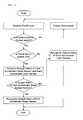
- FIG. 2 is a flowchart for implementing the selective use of the pedal by the system of the present invention.
- the ECU first determines whether the corresponding signal is a normal signal and, if it is determined that the corresponding signal is not a normal signal, outputs an error signal to the outside through a user notification means such as a warning light.
- a user notification means such as a warning light.
- the ECU recognizes that both the foot accelerator pedal and the hand accelerator lever are all used.
- the ECU compares the output values related to the engine RPM control set according to the positions of the foot accelerator pedal and the hand accelerator lever, selects a higher value (i.e., a higher speed side), and starts the engine RPM control based on the set RPM.
- the ECU controls the engine to reach an engine RPM, i.e., 2300 RPM, set by the hand accelerator lever.
- the ECU recognizes that only the hand accelerator lever is used, and thus the engine RPM is controlled based on the detection value of the hand accelerator lever sensor according to the change in the position of the hand accelerator lever, and in this case, the detection value of the foot accelerator pedal related to the operation of the foot accelerator pedal is ignored.
Landscapes
- Engineering & Computer Science (AREA)
- Chemical & Material Sciences (AREA)
- Combustion & Propulsion (AREA)
- Mechanical Engineering (AREA)
- General Engineering & Computer Science (AREA)
- Transportation (AREA)
- Control Of Throttle Valves Provided In The Intake System Or In The Exhaust System (AREA)
- Control Of Vehicle Engines Or Engines For Specific Uses (AREA)
- Auxiliary Drives, Propulsion Controls, And Safety Devices (AREA)
Abstract
Description
- The present invention relates to a system for selective use of a pedal for engine RPM control and, more particularly, to a system for selective use of a pedal for engine RPM control in a work vehicle equipped with an electronic engine, which is configured to selectively use a pedal related to the engine RPM control, i.e., engine speed control.
- A work vehicle, for example, an agricultural vehicle such as a tractor is structurally the same as a typical car but is equipped with a powerful engine to provide good traction. Thus, the agricultural vehicle is mainly used for agricultural purposes, and a working machine (e.g., rotary machine) suitable for seed covering or land leveling work may be selectively attached to the rear of the agricultural vehicle if necessary for the agricultural purposes.
- In the agricultural vehicle, the torque for driving the working machine is generated in a main engine of the agricultural vehicle and transferred to the working machine through a transmission case (not shown) and a power takeoff (PTO) shaft projecting from the rear of the agricultural vehicle. Here, the engine speed, i.e., the engine RPM is controlled depending on the amount of a driver's accelerator pedal operation.
- A conventional agricultural vehicle includes two accelerator pedals for convenience of operations related to the movement of the working machine depending on the work environment or the driver's position. One is a foot accelerator pedal that is used when the driver sitting on a driver's seat performs general works, and the other is a hand pedal (hereinafter referred to as "hand accelerator lever") used for the operation of the working machine when the operation of the foot accelerator pedal is difficult, e.g., when the driver works in a standing position.
- In a conventional agricultural vehicle equipped with a mechanical engine, the food accelerator pedal and the hand accelerator lever are interconnected by means of a wire during an idle operation of the engine and, and thus the engine RPM is controlled by a change in length of the wire according to a change in position of the foot accelerator pedal and/or the hand accelerator lever.
- In particular, to provide an environment for the selective use of the foot accelerator pedal and the hand accelerator lever, the conventional agricultural vehicle with the mechanical engine is equipped with a device for the implementation of the selective use of the pedal such that the engine RPM is controlled by one of the pedals, which has a larger change in the length of the wire according to the change in the position of the foot accelerator pedal and the hand accelerator lever.
- However, in the conventional agricultural with the mechanical engine which controls the engine RPM using the wire method, the engine RPM is controlled in such a mechanical manner using the wire, and thus it is difficult to precisely control the engine RPM. Moreover, the layout structure of the wire for implementing the selective use of the pedal is complicated, and a return spring or other additional components are required, resulting in a complicated configuration of the device.
- Recently, to make up for the drawbacks of the mechanical engine, there is a tendency to mount an electronically controlled engine (hereinafter referred to as "electronic engine"). In an agricultural vehicle equipped with the electronic engine, the displacement of the pedal due to the driver's operation is detected by a sensor, and the detection value of the sensor is calculated as an engine RPM control output value to control the engine output, thus providing more precise control.
- When the electronic engine is used, it is possible to make the device simpler and enable more precise engine control, compared to the conventional mechanical engine in which the output value is controlled by the wire method. However, in the case of the known agricultural vehicle equipped with the electronic engine, a separate system for the selective use of the foot accelerator pedal and the hand accelerator lever as in the mechanical engine is not provided, and thus it is impossible to selectively use the two pedals, which is problematic.
- Accordingly, the present invention has been made to solve the above-described problems, and an object of the present invention is to provide a system for selective use of a pedal for engine RPM control in a work vehicle equipped with an electronic engine, which allows a driver to selectively use a foot accelerator pedal and a hand accelerator pedal.
- To accomplish the above objects of the present invention, according to an aspect of the present invention there is provided a system for selective use of a pedal for engine RPM control in a work vehicle equipped with an electronic engine, the system comprising: a foot accelerator pedal sensor which detects an operation position of a foot accelerator pedal; a hand accelerator lever sensor which detects an operation position of a hand accelerator lever; a pedal select switch which is selectively switched by a user for selective or simultaneous use of the foot accelerator pedal and the hand accelerator lever; and an engine control unit (ECU) which is electrically connected to the pedal select switch and performs engine control at an engine RPM set by the foot accelerator pedal or the hand accelerator lever.
- In an embodiment, if the pedal select switch is ON, the ECU may recognize that both the foot accelerator pedal and the hand accelerator lever are all used, and if the pedal select switch is OFF, the ECU may recognize that only the hand accelerator lever is used.
- Moreover, if both the foot accelerator pedal and the hand accelerator lever are all used as the pedal select switch is set to ON, the ECU may select a higher value (i.e., a higher speed side) from output values related to the engine RPM control and set by the foot accelerator pedal and the hand accelerator lever and may perform the engine RPM control at an RPM corresponding to the selected value.
- The foot accelerator pedal sensor and the hand accelerator lever may output high and low electrical signals corresponding to the position values of the pedals according to a change in position of the foot accelerator pedal and the hand accelerator lever, the electrical signals being two electrical signals including a main signal and an auxiliary signal, and the output intensities of the main signal and the auxiliary signal may be set to have a constant difference within a predetermined range.
- If the output intensities of the main signal and the auxiliary signal fall within the predetermined range, the ECU may recognize that the electrical signal output from the foot accelerator pedal sensor or the hand accelerator lever sensor is a normal signal and may control the engine at an RPM by the main signal at the corresponding pedal position.
- Otherwise, if the output intensities of the main signal and the auxiliary signal exceed the predetermined range, the ECU may recognize that the electrical signal output from the foot accelerator pedal sensor or the hand accelerator lever sensor is not the normal signal and may output an error signal.
- According to an embodiment of the present invention, it is possible to implement a system capable of supporting the selective use of a foot accelerator pedal and a hand accelerator lever even in a work vehicle equipped with an electronic engine. Thus, even in the work vehicle equipped with the electronic engine, it is possible to select a pedal, which is easier to operate from the two pedals depending on the work environment or a driver's position, to effectively control the engine speed, i.e., the engine RPM, thus ensuring convenience of the pedal operation and implementing a work vehicle equipped with an electronic vehicle which can efficiently and effectively control the vehicle speed.
-
-
FIG. 1 is a block diagram schematically showing the configuration of a system for selective use of a pedal for engine RPM control in a work vehicle in accordance with an embodiment of the present invention. -
FIG. 2 is a flowchart for implementing the selective use of the pedal by the system of the present invention. -
- 10: foot accelerator pedal
- 12: foot accelerator pedal sensor
- 20: hand accelerator lever
- 22: hand accelerator lever sensor
- 30: pedal select switch
- 40: engine control unit (ECU)
- 90: engine
- Hereinafter, preferred embodiments of the present invention will be described in detail with reference to the accompanying drawings.
-
FIG. 1 is a block diagram schematically showing the configuration of a system for selective use of a pedal for engine RPM control in a work vehicle in accordance with an embodiment of the present invention. - Referring to
FIG. 1 , the system of the present invention comprises a pedalselect switch 30 which is selectively switched by a user for selective or simultaneous use of afoot accelerator pedal 10 and ahand accelerator lever 20 and an engine control unit (ECU) 40 which performs engine control in connection with the switching operation of thepedal select switch 30. - The
pedal select switch 30 is electrically connected to a battery (now shown) and theECU 40 and outputs a command for the selective or simultaneous use of two pedals (i.e., thefoot accelerator pedal 10 and the hand accelerator lever 20). If a command signal related to the pedal selection is input according to the operation of thepedal select switch 30, theECU 40 outputs a command signal for controlling the engine RPM at an RPM set by the corresponding selected pedal. - An
engine 90 is provide with a common rail type fuel injection unit (not shown) which electronically controls the amount of fuel injected or the injection timing, and the operation of the fuel injection unit is controlled in response to an RPM control signal of theECU 40. That is, the RPM of the engine may be controlled at a value set by the pedal through the control of the fuel injection unit in response to a control command of theECU 40. - The ECU 40 is electrically connected to a foot
accelerator pedal sensor 12 and a handaccelerator lever sensor 22 which detect the operation position of thefoot accelerator pedal 10 and thehand accelerator lever 20. Accordingly, theECU 40 calculates and outputs a signal for fuel injection control based on the detection value of the pedal operation position input from the footaccelerator pedal sensor 12 or the handaccelerator lever sensor 22. - In connection with the operation of the
pedal select switch 30, if thepedal select switch 30 is set to ON by a driver (or user), the ECU 40 recognizes that both thefoot accelerator pedal 10 and thehand accelerator lever 20 are all used. On the contrary, if thepedal select switch 30 is OFF, the ECU 40 recognizes that only thehand accelerator lever 20 is used,. - Of course, if the pedal
select switch 30 is set to ON by the driver (or user), theECU 40 may recognize that only thehand accelerator lever 20 is used, and if the pedalselect switch 30 is OFF, theECU 40 may recognize that both thefoot accelerator pedal 10 and thehand accelerator lever 20 are used at the same time, which may also be included in the scope of the present invention. - The case where if the pedal select
switch 30 is ON, the ECU 40 recognizes that both thefoot accelerator pedal 10 and thehand accelerator lever 20 are all used will be described by an example. When thepedal select switch 30 is ON, theECU 40 selects a higher value (i.e., a higher speed side) from output values related to the engine RPM control and set by thefoot accelerator pedal 10 and thehand accelerator lever 20 and performs control for maintaining the engine RPM at the selected value corresponding to the higher speed side. - The foot
accelerator pedal sensor 12 and the handaccelerator lever sensor 22 may output high and low electrical signals corresponding to the position values of the pedals according to the change in the position of thefoot accelerator pedal 10 and thehand accelerator lever 20. In this embodiment, the footaccelerator pedal sensor 12 and the handaccelerator lever sensor 22 output two electrical signals including a main signal and an auxiliary signal as the electrical signals corresponding to the position values of the pedals. - The output intensities of the main signal and the auxiliary signal are preset to have a constant difference within a predetermined range. If the output intensities of the main signal and the auxiliary signal fall within the predetermined range, the
ECU 40 recognizes that the electrical signal output from the footaccelerator pedal sensor 12 or the handaccelerator lever sensor 22 is a normal signal and thus controls the engine at an RPM by the main signal at the corresponding pedal position. - If the output intensities of the main signal and the auxiliary signal exceed the predetermined range, the
ECU 40 recognizes that the electrical signal output from the footaccelerator pedal sensor 12 or the handaccelerator lever sensor 22 is not the normal signal and, in this case, outputs an error signal through a user notification means such as a warning light. - The control process for the selective use of the pedal performed by the system having the above-described configuration will now be described in more detail in connection with the operation of the system according to the present invention.
-
FIG. 2 is a flowchart for implementing the selective use of the pedal by the system of the present invention. - Referring to
FIG. 2 , if a pedal operation signal is detected, the ECU first determines whether the corresponding signal is a normal signal and, if it is determined that the corresponding signal is not a normal signal, outputs an error signal to the outside through a user notification means such as a warning light. The system setup for the determination of the normal signal has been previously described in detail, and thus a repetitive description thereof will be omitted. - In a state where the detection signal in response to the pedal operation is the normal signal, if the pedal select switch is set to ON by a driver (or user), the ECU recognizes that both the foot accelerator pedal and the hand accelerator lever are all used.
- In a state where the pedal select switch is set to ON, if the foot accelerator pedal and/or the hand accelerator lever are operated, the ECU compares the output values related to the engine RPM control set according to the positions of the foot accelerator pedal and the hand accelerator lever, selects a higher value (i.e., a higher speed side), and starts the engine RPM control based on the set RPM.
- For example, if the foot accelerator pedal is in an operation position where the engine rotates at 2000 RPM and the hand accelerator lever is in an operation position where the engine rotates at 2300 RPM, the ECU controls the engine to reach an engine RPM, i.e., 2300 RPM, set by the hand accelerator lever.
- In the case where the pedal select switch is switched OFF during operation or where there is no operation of the pedal select switch from the beginning, the ECU recognizes that only the hand accelerator lever is used, and thus the engine RPM is controlled based on the detection value of the hand accelerator lever sensor according to the change in the position of the hand accelerator lever, and in this case, the detection value of the foot accelerator pedal related to the operation of the foot accelerator pedal is ignored.
- The invention has been described in detail with reference to preferred embodiments thereof. However, it will be appreciated by those skilled in the art that changes may be made in these embodiments without departing from the principles and spirit of the invention, the scope of which is defined in the appended claims and their equivalents.
Claims (7)
- A system for selective use of a pedal for engine RPM control in a work vehicle equipped with an electronic engine, the system comprising:a foot accelerator pedal sensor which detects an operation position of a foot accelerator pedal;a hand accelerator lever sensor which detects an operation position of a hand accelerator lever;a pedal select switch which is selectively switched by a user for selective or simultaneous use of the foot accelerator pedal and the hand accelerator lever; andan engine control unit (ECU) which is electrically connected to the pedal select switch and performs engine control at an engine RPM set by the foot accelerator pedal or the hand accelerator lever.
- The system of claim 1, wherein if the pedal select switch is ON, the ECU recognizes that both the foot accelerator pedal and the hand accelerator lever are all used, and if the pedal select switch is OFF, the ECU recognizes that only the hand accelerator lever is used.
- The system of claim 2, wherein if both the foot accelerator pedal and the hand accelerator lever are all used as the pedal select switch is set to ON, the ECU selects a higher value (i.e., a higher speed side) from output values related to the engine RPM control and set by the foot accelerator pedal and the hand accelerator lever and performs the engine RPM control at an RPM corresponding to the selected value.
- The system of claim 1, wherein the foot accelerator pedal sensor and the hand accelerator lever output high and low electrical signals corresponding to the position values of the pedals according to a change in position of the foot accelerator pedal and the hand accelerator lever, the electrical signals being two electrical signals including a main signal and an auxiliary signal.
- The system of claim 4, wherein the output intensities of the main signal and the auxiliary signal are set to have a constant difference within a predetermined range.
- The system of claim 5, wherein if the output intensities of the main signal and the auxiliary signal fall within the predetermined range, the ECU recognizes that the electrical signal output from the foot accelerator pedal sensor or the hand accelerator lever sensor is a normal signal and controls the engine at an RPM by the main signal at the corresponding pedal position.
- The system of claim 5, wherein if the output intensities of the main signal and the auxiliary signal exceed the predetermined range, the ECU recognizes that the electrical signal output from the foot accelerator pedal sensor or the hand accelerator lever sensor is not the normal signal and outputs an error signal.
Applications Claiming Priority (2)
| Application Number | Priority Date | Filing Date | Title |
|---|---|---|---|
| KR1020110002690A KR20120081377A (en) | 2011-01-11 | 2011-01-11 | Pedal selective using system for engine speed control |
| PCT/KR2012/000280 WO2012096518A2 (en) | 2011-01-11 | 2012-01-11 | System for selective use of pedal for controlling number of revolution for engine of work vehicle |
Publications (2)
| Publication Number | Publication Date |
|---|---|
| EP2664769A2 true EP2664769A2 (en) | 2013-11-20 |
| EP2664769A4 EP2664769A4 (en) | 2015-07-15 |
Family
ID=46507578
Family Applications (1)
| Application Number | Title | Priority Date | Filing Date |
|---|---|---|---|
| EP12734342.4A Withdrawn EP2664769A4 (en) | 2011-01-11 | 2012-01-11 | System for selective use of pedal for controlling number of revolution for engine of work vehicle |
Country Status (4)
| Country | Link |
|---|---|
| US (1) | US20130291832A1 (en) |
| EP (1) | EP2664769A4 (en) |
| KR (1) | KR20120081377A (en) |
| WO (1) | WO2012096518A2 (en) |
Cited By (2)
| Publication number | Priority date | Publication date | Assignee | Title |
|---|---|---|---|---|
| WO2015067607A1 (en) * | 2013-11-06 | 2015-05-14 | Horsch Leeb Application Systems Gmbh | Method and device for controlling a velocity of an agricultural machine |
| WO2016156417A1 (en) * | 2015-03-31 | 2016-10-06 | Agco International Gmbh | A vehicle throttle system |
Families Citing this family (6)
| Publication number | Priority date | Publication date | Assignee | Title |
|---|---|---|---|---|
| KR101361820B1 (en) * | 2011-01-11 | 2014-02-24 | 대동공업주식회사 | Engine speed control system and control methods of agriculture vehicle |
| CN107989703B (en) * | 2017-12-15 | 2024-05-14 | 三江瓦力特特种车辆有限公司 | Engine throttle switching circuit |
| CN111422061B (en) * | 2018-03-01 | 2021-07-30 | 国网山东省电力公司武城县供电公司 | Engine rotating speed control method |
| CN110670663A (en) * | 2019-10-31 | 2020-01-10 | 徐工集团工程机械股份有限公司科技分公司 | Skid Steer Electronic Dual Throttle System |
| CN112297840B (en) * | 2020-11-04 | 2021-05-18 | 徐州徐工随车起重机有限公司 | Accelerator acceleration control device without controller |
| CN115750121A (en) * | 2022-12-27 | 2023-03-07 | 徐工集团工程机械股份有限公司科技分公司 | Throttle control system of loader |
Family Cites Families (14)
| Publication number | Priority date | Publication date | Assignee | Title |
|---|---|---|---|---|
| DE19602006A1 (en) * | 1995-01-28 | 1996-08-01 | Luk Getriebe Systeme Gmbh | Device and a method for controlling a torque transmission system |
| JPH1150868A (en) * | 1997-08-04 | 1999-02-23 | Yanmar Agricult Equip Co Ltd | Engine speed adjustment configuration for traveling vehicles |
| KR100328216B1 (en) * | 1997-12-02 | 2002-06-24 | 볼보 컨스트럭션 이키프먼트 홀딩 스웨덴 에이비 | engine torque control system |
| DE19844822A1 (en) * | 1998-09-30 | 2000-04-20 | Gen Motors Corp | Method and device for controlling the energy supply of a motor vehicle engine |
| KR100325163B1 (en) * | 1999-07-08 | 2002-02-25 | 이계안 | System for controlling power take off of vehicles |
| US6493618B2 (en) * | 2000-03-15 | 2002-12-10 | Toyota Jidosha Kabushiki Kaisha | Vehicle control using multiple sensors |
| JP3819699B2 (en) * | 2000-10-20 | 2006-09-13 | 日立建機株式会社 | Hydraulic traveling vehicle |
| US7974760B2 (en) * | 2003-10-20 | 2011-07-05 | Nmhg Oregon, Inc. | Advanced power-shift transmission control system |
| JP4294012B2 (en) * | 2005-07-28 | 2009-07-08 | 三菱電機株式会社 | Electronic throttle control device |
| CA2572595C (en) * | 2006-01-26 | 2011-03-29 | Honda Motor Co., Ltd | Engine-driven work machine |
| US7963883B2 (en) * | 2008-01-10 | 2011-06-21 | Deere & Company | Propulsion system for skidder |
| KR100986932B1 (en) * | 2008-05-29 | 2010-10-08 | 가부시끼 가이샤 구보다 | Engine speed control system for work car |
| KR101163182B1 (en) * | 2009-02-27 | 2012-07-06 | 가부시키가이샤 덴소 | System for restarting internal combustion engine when engine restart condition is met |
| US8100217B2 (en) * | 2009-06-12 | 2012-01-24 | Ford Global Technologies, Llc | Vehicle with hand control system |
-
2011
- 2011-01-11 KR KR1020110002690A patent/KR20120081377A/en not_active Ceased
-
2012
- 2012-01-11 WO PCT/KR2012/000280 patent/WO2012096518A2/en not_active Ceased
- 2012-01-11 EP EP12734342.4A patent/EP2664769A4/en not_active Withdrawn
- 2012-01-11 US US13/979,050 patent/US20130291832A1/en not_active Abandoned
Non-Patent Citations (1)
| Title |
|---|
| See references of WO2012096518A2 * |
Cited By (3)
| Publication number | Priority date | Publication date | Assignee | Title |
|---|---|---|---|---|
| WO2015067607A1 (en) * | 2013-11-06 | 2015-05-14 | Horsch Leeb Application Systems Gmbh | Method and device for controlling a velocity of an agricultural machine |
| WO2016156417A1 (en) * | 2015-03-31 | 2016-10-06 | Agco International Gmbh | A vehicle throttle system |
| CN107405999A (en) * | 2015-03-31 | 2017-11-28 | 爱科国际有限公司 | Vehicle accelerator system |
Also Published As
| Publication number | Publication date |
|---|---|
| WO2012096518A3 (en) | 2012-10-18 |
| KR20120081377A (en) | 2012-07-19 |
| EP2664769A4 (en) | 2015-07-15 |
| US20130291832A1 (en) | 2013-11-07 |
| WO2012096518A2 (en) | 2012-07-19 |
Similar Documents
| Publication | Publication Date | Title |
|---|---|---|
| US20130291832A1 (en) | System for selective use of pedal for controlling number of revolution for engine of work vehicle | |
| US7899597B2 (en) | Work machine with operator presence detection strategy | |
| US9014941B2 (en) | System and method for validating adaptive cruise control operations | |
| EP1616744A1 (en) | Preceding vehicle following cruise control system | |
| US9818241B2 (en) | Malfunction diagnosing apparatus for vehicle | |
| EP3225453A1 (en) | Regeneration control apparatus | |
| KR100986932B1 (en) | Engine speed control system for work car | |
| SE454905B (en) | DEVICE FOR SPEED ADJUSTMENT OF A ENGINE IN A WORKING MACHINE | |
| US7908068B2 (en) | Engine controller of hydraulic shovel | |
| US8131434B2 (en) | Engine speed control system for work vehicle | |
| EP2664770A2 (en) | System for controlling number of revolution for engine of farm work vehicle having electronic engine attached thereon and method for controlling thereof | |
| EP2779413B1 (en) | Drive system and method for driving a vehicle | |
| US8912745B2 (en) | Method for operating a motor control unit for a drive system | |
| US20170016209A1 (en) | Work Vehicle | |
| EP2949971B1 (en) | Working vehicle | |
| JP2004190615A (en) | Apparatus and method for switching torque characteristics | |
| KR20130084071A (en) | Travel system of construction machine and method thereof | |
| KR101260751B1 (en) | Method for controlling drive motor of eleltric tractor | |
| JP6407103B2 (en) | Working machine | |
| KR102040214B1 (en) | Engine on/off auto control system of Saddle type rice transplanter and rice transplanter containing the same | |
| KR101305652B1 (en) | A traveling system of wheel loader | |
| KR20140095210A (en) | Engine speed control system and control methods of agriculture vehicle | |
| KR100507146B1 (en) | Power take-off system and method thereof | |
| KR100288220B1 (en) | power take off control system | |
| JP2003034157A (en) | Transmission shift control device and transmission shift operation device |
Legal Events
| Date | Code | Title | Description |
|---|---|---|---|
| PUAI | Public reference made under article 153(3) epc to a published international application that has entered the european phase |
Free format text: ORIGINAL CODE: 0009012 |
|
| 17P | Request for examination filed |
Effective date: 20130711 |
|
| AK | Designated contracting states |
Kind code of ref document: A2 Designated state(s): AL AT BE BG CH CY CZ DE DK EE ES FI FR GB GR HR HU IE IS IT LI LT LU LV MC MK MT NL NO PL PT RO RS SE SI SK SM TR |
|
| DAX | Request for extension of the european patent (deleted) | ||
| A4 | Supplementary search report drawn up and despatched |
Effective date: 20150612 |
|
| RIC1 | Information provided on ipc code assigned before grant |
Ipc: F02D 31/00 20060101ALI20150608BHEP Ipc: F02D 41/04 20060101ALI20150608BHEP Ipc: F02D 11/02 20060101AFI20150608BHEP Ipc: F02D 11/10 20060101ALI20150608BHEP Ipc: F02D 29/00 20060101ALI20150608BHEP Ipc: F02D 41/22 20060101ALN20150608BHEP Ipc: B60K 26/02 20060101ALI20150608BHEP |
|
| STAA | Information on the status of an ep patent application or granted ep patent |
Free format text: STATUS: THE APPLICATION IS DEEMED TO BE WITHDRAWN |
|
| 18D | Application deemed to be withdrawn |
Effective date: 20160111 |