EP2664544A2 - Method for controlling an aircraft air conditioning system and aircraft air conditioning system - Google Patents
Method for controlling an aircraft air conditioning system and aircraft air conditioning system Download PDFInfo
- Publication number
- EP2664544A2 EP2664544A2 EP12002004.5A EP12002004A EP2664544A2 EP 2664544 A2 EP2664544 A2 EP 2664544A2 EP 12002004 A EP12002004 A EP 12002004A EP 2664544 A2 EP2664544 A2 EP 2664544A2
- Authority
- EP
- European Patent Office
- Prior art keywords
- air
- mixing chamber
- volume flow
- air conditioning
- aircraft
- Prior art date
- Legal status (The legal status is an assumption and is not a legal conclusion. Google has not performed a legal analysis and makes no representation as to the accuracy of the status listed.)
- Granted
Links
Images


Classifications
-
- B—PERFORMING OPERATIONS; TRANSPORTING
- B64—AIRCRAFT; AVIATION; COSMONAUTICS
- B64D—EQUIPMENT FOR FITTING IN OR TO AIRCRAFT; FLIGHT SUITS; PARACHUTES; ARRANGEMENTS OR MOUNTING OF POWER PLANTS OR PROPULSION TRANSMISSIONS IN AIRCRAFT
- B64D13/00—Arrangements or adaptations of air-treatment apparatus for aircraft crew or passengers, or freight space, or structural parts of the aircraft
- B64D13/06—Arrangements or adaptations of air-treatment apparatus for aircraft crew or passengers, or freight space, or structural parts of the aircraft the air being conditioned
- B64D13/08—Arrangements or adaptations of air-treatment apparatus for aircraft crew or passengers, or freight space, or structural parts of the aircraft the air being conditioned the air being heated or cooled
-
- B—PERFORMING OPERATIONS; TRANSPORTING
- B64—AIRCRAFT; AVIATION; COSMONAUTICS
- B64D—EQUIPMENT FOR FITTING IN OR TO AIRCRAFT; FLIGHT SUITS; PARACHUTES; ARRANGEMENTS OR MOUNTING OF POWER PLANTS OR PROPULSION TRANSMISSIONS IN AIRCRAFT
- B64D13/00—Arrangements or adaptations of air-treatment apparatus for aircraft crew or passengers, or freight space, or structural parts of the aircraft
- B64D13/06—Arrangements or adaptations of air-treatment apparatus for aircraft crew or passengers, or freight space, or structural parts of the aircraft the air being conditioned
- B64D2013/0603—Environmental Control Systems
- B64D2013/0611—Environmental Control Systems combined with auxiliary power units (APU's)
-
- B—PERFORMING OPERATIONS; TRANSPORTING
- B64—AIRCRAFT; AVIATION; COSMONAUTICS
- B64D—EQUIPMENT FOR FITTING IN OR TO AIRCRAFT; FLIGHT SUITS; PARACHUTES; ARRANGEMENTS OR MOUNTING OF POWER PLANTS OR PROPULSION TRANSMISSIONS IN AIRCRAFT
- B64D13/00—Arrangements or adaptations of air-treatment apparatus for aircraft crew or passengers, or freight space, or structural parts of the aircraft
- B64D13/06—Arrangements or adaptations of air-treatment apparatus for aircraft crew or passengers, or freight space, or structural parts of the aircraft the air being conditioned
- B64D2013/0603—Environmental Control Systems
- B64D2013/0655—Environmental Control Systems with zone or personal climate controls
-
- B—PERFORMING OPERATIONS; TRANSPORTING
- B64—AIRCRAFT; AVIATION; COSMONAUTICS
- B64D—EQUIPMENT FOR FITTING IN OR TO AIRCRAFT; FLIGHT SUITS; PARACHUTES; ARRANGEMENTS OR MOUNTING OF POWER PLANTS OR PROPULSION TRANSMISSIONS IN AIRCRAFT
- B64D13/00—Arrangements or adaptations of air-treatment apparatus for aircraft crew or passengers, or freight space, or structural parts of the aircraft
- B64D13/06—Arrangements or adaptations of air-treatment apparatus for aircraft crew or passengers, or freight space, or structural parts of the aircraft the air being conditioned
- B64D2013/0603—Environmental Control Systems
- B64D2013/0688—Environmental Control Systems with means for recirculating cabin air
-
- Y—GENERAL TAGGING OF NEW TECHNOLOGICAL DEVELOPMENTS; GENERAL TAGGING OF CROSS-SECTIONAL TECHNOLOGIES SPANNING OVER SEVERAL SECTIONS OF THE IPC; TECHNICAL SUBJECTS COVERED BY FORMER USPC CROSS-REFERENCE ART COLLECTIONS [XRACs] AND DIGESTS
- Y02—TECHNOLOGIES OR APPLICATIONS FOR MITIGATION OR ADAPTATION AGAINST CLIMATE CHANGE
- Y02T—CLIMATE CHANGE MITIGATION TECHNOLOGIES RELATED TO TRANSPORTATION
- Y02T50/00—Aeronautics or air transport
- Y02T50/50—On board measures aiming to increase energy efficiency
Definitions
- the predetermined maximum value of the volume flow of recirculation air into the mixing chamber may be a volume flow value that is determined in dependence on the heating demand of the aircraft region to be air conditioned and the actual temperature of the recirculation air.
- the volume flow of compressed air into the mixing chamber may be increased from the predetermined minimum value, if the heating demand of the aircraft region to be air conditioned cannot be met by further increasing the volume flow of recirculation air, for example, due to performance restrictions of the recirculation fans or since the actual temperature of the recirculation air is too low.
- Figure 6 shows a flow diagram of a method for operating the air conditioning system 10 in a cooling mode, i.e., a method for operating the aircraft air conditioning system 10 in case a cooling demand of the aircraft region 28 to be air conditioned is determined by the electronic control unit 48.
- the control unit 34 in a first step, again analyses whether the volume flow of compressed air into the mixing chamber 26 exceeds the predetermined minimum value or not.
- the control strategy is not changed, i.e., the volume flows of compressed air and recirculation air into the mixing chamber 26 are kept constant.
Abstract
Description
- The present invention relates to a method for controlling an aircraft air conditioning system and to an aircraft air conditioning system.
- So-called air-based air conditioning systems, as described for example in
DE 10 2008 053 320 A1 or non-publishedDE 10 2010 054 448 , are usually used at present in commercial aircraft to air-condition the aircraft cabin. An aircraft air conditioning system serves to cool the aircraft cabin, which would otherwise be overheated due to thermal loads, such as, for example, body heat of the passengers and waste heat from equipment present on board the aircraft. The aircraft air conditioning system in addition adequately supplies fresh air into the aircraft cabin to ensure that a prescribed minimum proportion of oxygen is present in the aircraft cabin. - Air-based air conditioning systems typically comprise an air conditioning unit, which is arranged, for example, in a wing root of the aircraft, and which is supplied with compressed process air that is generated by a compressor or bled of from an engine or an auxiliary power unit (APU) of the aircraft. During flight operation of the aircraft, usually engine bleed air is used so as to supply the air conditioning unit of the aircraft air conditioning system with compressed process air. During ground operation of the aircraft the air conditioning unit of the aircraft air conditioning system, however, typically is supplied with compressed process air from the auxiliary power unit of the aircraft. In the air conditioning unit, the process air, upon flowing through at least one heat exchanger as well as through various compression and expansion units, is cooled and expanded. Cooled process air exiting the air conditioning unit finally is supplied to a mixing chamber where it is mixed with recirculation recirculated from an aircraft region to be air conditioned. The mixed air from the mixing chamber, via respective mixed air lines, is supplied to the aircraft region to be air conditioned which may be divided into a plurality of air conditioning zones.
- The invention is directed at the object of specifying a method for controlling an aircraft air conditioning system, that allows a source of compressed process air to be supplied to the aircraft air conditioning system, such as for example an auxiliary power unit, to be operated in an energy-efficient manner. Further, the invention is directed at the object of providing an aircraft air condition system, that allows a source of compressed process air to be supplied to the aircraft air conditioning system, such as for example an auxiliary power unit, to be operated in an energy-efficient manner.
- This object is achieved by a method for controlling an aircraft air conditioning system having the features of Claim 1 and an aircraft air conditioning system having the features of Claim 8.
- In a method, according to the invention, for controlling an aircraft air conditioning system, in a first step, a heating demand or a cooling demand of an aircraft region to be air conditioned is detected. The aircraft region to be air conditioned may be an aircraft passenger cabin, a cockpit, a freight compartment or any other aircraft region. The heating or cooling demand of the aircraft region to be air conditioned may, for example, be detected on the basis of a comparison of a set temperature in the aircraft region to be air conditioned with an actual temperature in the aircraft region to be air conditioned, wherein the actual temperature in the aircraft region to be air conditioned may, for example, be measured by a suitable temperature sensor. The set temperature in the aircraft region to be air conditioned may, for example, be determined by a user and entered via a suitable user interface of the air conditioning system or may be a temperature value which is stored in a control unit, preferably an electronic control unit for controlling the operation of the aircraft air conditioning system. The control unit for controlling the operation of the aircraft air conditioning system may also be used for determining the heating or cooling demand of the aircraft region to be air conditioned.
- Further, in the method for controlling an aircraft air conditioning system, a volume flow of recirculation air discharged from the aircraft region to be air conditioned and a volume flow of compressed air into a mixing chamber of the aircraft air conditioning system is controlled such that the heating or cooling demand of the aircraft region to be air conditioned is met, while the volume flow of compressed air into the mixing chamber of the aircraft air conditioning system is minimized. In the method for controlling an aircraft air conditioning system the volume flow of recirculation air thus, beside the volume flow of compressed air into the mixing chamber of the aircraft air conditioning system, is used as a direct control parameter for controlling the operation of the aircraft air conditioning system in dependence on the heating or cooling demand of the aircraft region to be air conditioned. This allows the implementation of a control strategy aiming at a minimization of the volume flow of compressed air into the mixing chamber of the aircraft air conditioning system.
- The compressed air may be provided by a compressed air source, such as for example a compressor, an engine or an auxiliary power unit of the aircraft. The compressed air provided by the compressed air source may be cooled and expanded in an air conditioning unit of the aircraft air conditioning system. The air cooled by the air conditioning unit, for appropriately adjusting the temperature of the air which is finally supplied to the mixing chamber, in an exit region of the air conditioning unit may be mixed with additional compressed hot air supplied from the compressed air source. "Compressed air" in the context of the present application thus may contain compressed air from a compressed air source which is cooled and expanded in an air conditioning unit and/or hot compressed air which is directly bled off the compressed air source.
- By minimizing the use of compressed air during operation of the aircraft air conditioning system, the performance requirements placed on the compressed air source can be reduced. Specifically, the method for controlling an aircraft air conditioning system allows a particularly energy efficient operation of the compressed air source. Further, in particular if an engine or an auxiliary power unit of the aircraft is used as the compressed air source, fuel consumption and wear of the engine or the auxiliary power unit can be reduced.
- If a heating demand of the aircraft region to be air conditioned is determined and the volume flow of compressed air exceeds a predetermined minimum value, a volume flow of recirculation air discharged from the aircraft region to be air conditioned into the mixing chamber may be increased. In case the aircraft region to be air conditioned should be heated, a set temperature of the mixed air in the mixing chamber typically is relatively high and may, for example, be between approximately 15 to approximately 70°C. By increasing the volume flow of typically relatively warm recirculation air into the mixing chamber the actual temperature of the mixed air in the mixing chamber may be increased so as to approach the set temperature. The volume flow of recirculation air from the aircraft region to be air conditioned into the mixing chamber may be increased, for example, by increasing the speed of recirculation fans conveying the recirculation air from the aircraft region to be air conditioned into the mixing chamber.
- The volume flow of compressed air into the mixing chamber then is decreased in dependence on the increase of the volume flow of recirculation air into the mixing chamber. Preferably, the volume flow of recirculation air discharged from the aircraft region to be air conditioned into the mixing chamber is increased and the volume flow of compressed air into the mixing chamber is decreased until it has reached the predetermined minimum value allowing a particularly energy efficient operation of the compressed air source. The decrease of the volume flow of compressed air into the mixing chamber may be adjusted to the increase of the volume flow of recirculation air into the mixing chamber such that a combined volume flow of recirculation air and compressed air is kept constant.
- As discussed above, the control strategy of increasing the recirculation air volume flow and correspondingly decreasing the compressed air volume flow into the mixing chamber is implemented only if the volume flow of compressed air into the mixing chamber still has not reached the predetermined minimum value. The volume flow of compressed air into the mixing chamber preferably corresponds to the predetermined minimum value, when an air conditioning unit of the aircraft air conditioning system is operated with its maximum cooling capacity, i.e., cools the compressed air to the lowest possible temperature, and a supply of hot compressed air to the air cooled by the air conditioning unit is interrupted.
- Upon decreasing the volume flow of compressed air into the mixing chamber it is possible to first decrease the volume flow of air cooled by the air conditioning unit and to then decrease the supply of hot compressed air to the air cooled by the air conditioning unit in dependence on the decrease of the volume flow of air cooled by the air conditioning unit. It is, however, also conceivable to implement a decrease of the volume flow of compressed air into the mixing chamber by first decreasing the supply of hot compressed air to the air cooled by the air conditioning unit and by then decreasing the volume flow of air cooled by the air conditioning unit in dependence on the decrease of the supply of hot compressed air to the air cooled by the air conditioning unit.
- The supply of hot compressed air to the air cooled by the air conditioning unit may be decreased and finally interrupted by closing a bypass valve provided in a bypass line being connected to the compressed air source and opening into a line connecting the air conditioning unit to the mixing chamber downstream of the air conditioning unit. The bypass valve may be a valve having a variable flow cross section. When the bypass valve is fully closed, the supply of hot compressed air to the air cooled by the air conditioning unit is interrupted.
- Preferably, after the volume flow of compressed air into the mixing chamber has reached the predetermined minimum value, the increase of the volume flow of recirculation air into the mixing chamber is stopped, as soon as an actual temperature of the mixed air in the mixing chamber corresponds to a set temperature of the mixed air in the mixing chamber. The set temperature of the mixed air in the mixing chamber may be associated with the heating demand of the aircraft region to be air conditioned.
- The volume flow of compressed air into the mixing chamber may be increased from the predetermined minimum value, if it is determined that an actual temperature of the mixed air in the mixing chamber is below a set temperature of the mixed air in the mixing chamber, although the volume flow of recirculation air into the mixing chamber has reached a predetermined maximum value. The volume flow of recirculation air into the mixing chamber may correspond to the predetermined maximum value, for example, when recirculation fans conveying the recirculation air from the aircraft region to be air conditioned to the mixing chamber are operated with the maximum speed. Alternatively thereto, the predetermined maximum value of the volume flow of recirculation air into the mixing chamber may be a volume flow value that is determined in dependence on the heating demand of the aircraft region to be air conditioned and the actual temperature of the recirculation air. In fact, the volume flow of compressed air into the mixing chamber may be increased from the predetermined minimum value, if the heating demand of the aircraft region to be air conditioned cannot be met by further increasing the volume flow of recirculation air, for example, due to performance restrictions of the recirculation fans or since the actual temperature of the recirculation air is too low.
- If a cooling demand of the aircraft region to be air conditioned is determined and the volume flow of compressed air into the mixing chamber exceeds a predetermined minimum value, a volume flow of air cooled by the air conditioning unit of the aircraft air conditioning system into the mixing chamber may be decreased. As a result, the actual temperature of the mixed air in the mixing chamber increases. Therefore, a volume flow of hot compressed air which is supplied to the air cooled by the air conditioning unit is decreased in dependence on the decrease of the volume flow of air cooled by the air conditioning unit. As a result, the increase of the temperature of the mixed air in the mixing chamber caused by the reduction of the volume flow of air cooled by the air conditioning unit can be compensated for. Further, the combined compressed air volume flow formed by the volume flow of air cooled by the air conditioning unit and the volume flow of hot compressed air which is supplied to the air cooled by the air conditioning unit is reduced. Preferably, the volume flow of air cooled by the air conditioning unit into the mixing chamber and the volume flow of compressed air which is supplied to the air cooled by the air conditioning unit are decreased until the air conditioning unit is operated with its maximum cooling capacity, i.e., cools the compressed air to the lowest possible temperature, and a supply of hot compressed air to the air cooled by the air conditioning unit is minimized and, if possible, interrupted.
- If the aircraft region to be air conditioned should be cooled, and it is determined that hot compressed air is supplied to the air cooled by the air conditioning unit, although the air conditioning unit is operated with its maximum cooling capacity, the volume flow of recirculation air into the mixing chamber may be increased. Due to the increase of the volume flow of relatively warm recirculating air into the mixing chamber, the supply of hot compressed air to the air cooled by the air conditioning unit may be decreased in dependence on the increase of the volume flow of recirculation air into the mixing chamber. As a result, the combined volume flow of compressed air into the mixing chamber can further be reduced.
- An aircraft air conditioning system comprises means for determining a heating or cooling demand of an aircraft region to be air conditioned and a control unit which is adapted to control a volume flow of recirculation air discharged from the aircraft region to be air conditioned and a volume flow of compressed air into a mixing chamber of the aircraft air conditioning system such that the heating or cooling demand of the aircraft region to be air conditioned is met, while the volume flow of compressed air to the mixing chamber of the aircraft air conditioning system is minimized.
- If a heating demand of the aircraft region to be air conditioned is determined and a volume flow of compressed air into the mixing chamber exceeds a predetermined minimum value, the control unit may be adapted to increase a volume flow of recirculation air discharged from the aircraft region to be air conditioned into the mixing chamber, and to decrease the volume flow of compressed air into the mixing chamber in dependence of the increase of the volume flow of recirculation air into the mixing chamber. Preferably, this control strategy is implemented until the volume flow of compressed air into the mixing chamber has reached the predetermined minimum value.
- Preferably, the volume flow of compressed air into the mixing chamber corresponds to the predetermined minimum value, when an air conditioning unit of the aircraft air conditioning system is operated with its maximum cooling capacity, and a supply of hot compressed air to the air cooled by the air conditioning unit is interrupted.
- The control unit may be adapted to stop the increase of the volume flow of recirculation air into the mixing chamber, after the volume flow of compressed air into the mixing chamber has reached the predetermined minimum value, as soon as an actual temperature of the mixed air in the mixing chamber corresponds to a set temperature of the mixed air in the mixing chamber, the set temperature of the mixed air in the mixing chamber being associated with the heating demand of the aircraft region to be air conditioned.
- The control unit may further be adapted to increase the volume flow of compressed air into the mixing chamber from the predetermined minimum value, if it is determined that an actual temperature of the mixed air in the mixing chamber is below a set temperature of the mixed air in the mixing chamber, although the volume flow of recirculation air into the mixing chamber has reached a predetermined maximum value.
- If a cooling demand of the aircraft region to be air conditioned is determined and a volume flow of compressed air into the mixing chamber exceeds a predetermined minimum value, the control unit may be adapted to decrease a volume flow of air cooled by the air conditioning unit of the aircraft air conditioning system into the mixing chamber, and to decrease a volume flow of hot compressed air which is supplied to the air cooled by the air conditioning unit. Preferably, this control strategy is implemented until the air conditioning unit of the aircraft air conditioning system is operated with its maximum cooling capacity..
- The control unit may be adapted to decrease the volume flow of hot compressed air which is supplied to the air cooled by the air conditioning unit by closing a bypass valve provided in a bypass line being connected to a compressed air source and opening into a line connecting the air conditioning unit to the mixing chamber downstream of the air conditioning unit.
- The control unit may be adapted to increase the volume flow of recirculation air into the mixing chamber if it is determined that hot compressed air is supplied to the air cooled by the air conditioning unit, although the air conditioning unit of the aircraft air conditioning system is operated with its maximum cooling capacity. The control unit may further be adapted to decrease the volume flow of hot compressed air which is supplied to the air cooled by the air conditioning unit in dependence on the increase of the volume flow of recirculation air into the mixing chamber.
- A preferred embodiment of the invention in the following will be described in more detail with reference to the appended schematic drawings, in which
- Figure 1
- shows an aircraft air conditioning system which is supplied with compressed fresh air by means of an auxiliary power unit,
- Figure 2
- shows a detail of the aircraft air conditioning system according to
Figure 1 , - Figure 3
- shows an air distribution system of the aircraft air conditioning system according to
Figure 1 , - Figure 4
- shows a diagram depicting the control of the aircraft air conditioning system according to
Figure 1 , - Figure 5
- shows a flow diagram of a method for operating the aircraft air conditioning system according to
Figure 1 in a heating mode, and - Figure 6
- shows a flow diagram of a method for operating the aircraft air conditioning system according to
Figure 1 in a cooling mode. -
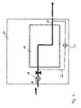
Figure 1 shows an aircraftair conditioning system 10, which, during ground operation of the aircraft, is supplied with compressed process air from an auxiliary power unit 1. The compressed air generated by theauxiliary power unit 12 is supplied to the aircraftair conditioning system 10, specifically anair conditioning unit 14 of theair conditioning 10 via aline 16. As becomes apparent fromFigure 2 , avalve 18 is disposed in theline 16 which controls the supply of compressed process air into theair conditioning unit 14 of the aircraftair conditioning system 10. In theair conditioning unit 14 the process air, upon flowing through at least one heat exchanger and upon flowing through various compression and expansion units, is cooled and expanded. - Cool process air exits the
air conditioning unit 14 via afurther line 20. Abypass line 22 branches off from theline 16 upstream of theair conditioning unit 14 and opens into theline 20 downstream of theair conditioning unit 14. Abypass valve 24 is disposed in thebypass line 22. Hot process air bled off theauxiliary power unit 12, via thebypass line 22, may bypass theair conditioning unit 14 and may be mixed with the cool air exiting theair conditioning unit 14 downstream of theair conditioning unit 14. Thus, by appropriately controlling thebypass valve 14, the temperature of the process air at the exit of theair conditioning unit 14 may be controlled as desired. - As depicted in
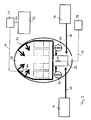
Figure 3 , via thefurther line 20, compressed air, which may be a mixture of air cooled and expanded by theair conditioning unit 14 and hot compressed air which is supplied to the air cooled in theair conditioning unit 14 via thebypass line 22, is guided into a mixingchamber 26. In the mixingchamber 26 the compressed air is mixed with recirculation air discharged from anaircraft region 28 to be air conditioned by means ofrecirculation fans 30. Mixed air from the mixingchamber 26 finally is supplied to theaircraft region 28 to be air conditioned via anair distribution system 32. - The operation of the aircraft
air conditioning system 10 is controlled by means of anelectronic control unit 34. Anelectronic control unit 36 serves to control the operation of theauxiliary power unit 12. Afirst signal line 38 connects thecontrol unit 36 for controlling theauxiliary power unit 12 to theauxiliary power unit 12. A second signal line 40 connects theelectronic control unit 34 for controlling theair conditioning system 10 to theair conditioning unit 14. Further, theelectronic control unit 34 is connected to therecirculation fans 30 and adapted to control the operation of therecirculation fans 30. Moreover, theelectronic control unit 34 is connected to thebypass valve 24 and adapted to control the operation of thebypass valve 24. Finally, thecontrol units third signal line 42. - As becomes apparent from
Figures 3 and4 , atemperature sensor 44 is disposed in theaircraft region 28 to be air conditioned, which, via afourth signal line 46, provides signals indicative of the actual temperature in theaircraft region 28 to be air conditioned to anelectronic control unit 48. Theelectronic control unit 48, via afifth signal line 50, is connected to aninput device 52. Upon start-up of the aircraftair conditioning system 10 theelectronic control unit 48 determines a heating or cooling demand of theaircraft region 28 to be air conditioned. For determining the heating or cooling demand of theaircraft region 28 to be air conditioned, the electronic control unit 48may, for example, compare an actual temperature in theaircraft region 28 to be air conditioned with a set temperature in theaircraft region 28 to be air conditioned. The actual temperature in theaircraft region 28 to be air conditioned may be measured by means of thetemperature sensor 44 which is disposed in theaircraft region 28 to be air conditioned. The set temperature in theaircraft region 28 to be air conditioned may, for example, be input by a user via theinput device 52 or may be stored in a storage device of theelectronic control unit 48. - A
further temperature sensor 54 is disposed in the mixingchamber 26 of theair conditioning system 10. Asixth signal line 46 connects the temperature sensor to anelectronic control unit 58. Based the heating or cooling demand of theaircraft region 28 to be air conditioned, which is communicated to theelectronic control unit 58 via aseventh signal line 60, theelectronic control unit 58 determines a set temperature of the mixed air in the mixingchamber 26. Further, theelectronic control unit 58 compares the set temperature of the mixed air in the mixingchamber 26 with the actual temperature of the mixed air in the mixingchamber 26 which is measured by means of thetemperature sensor 54. - The
electronic control unit 48 and theelectronic control 58 both, via an eighth signal line 62, communicate with theelectronic control unit 34 of theair conditioning system 10. Based on the data provided by theelectronic control units electronic control unit 34 controls the operation of theair conditioning unit 14 and thus the temperature and the volume flow of cool air exiting theair conditioning unit 14. Further, theelectronic control unit 34 controls thebypass valve 24 and thus the supply of hot compressed air to the cool air exiting theair conditioning unit 14. Finally, theelectronic control unit 34 controls the operation of therecirculation fans 30 and thus the volume flow of recirculation air conveyed by therecirculation fans 30 from theaircraft region 28 to be air conditioned into the mixingchamber 26. Theelectronic control unit 34, via thethird signal line 42, communicates with theelectronic control unit 36 of theauxiliary power unit 12 which controls the operation of theauxiliary power unit 12 in dependence on the data provided by theelectronic control unit 34 of theair conditioning system 10. - It should be noted that the above described distribution of control tasks to different electronic control units is merely an example of how the
air conditioning system 10 and theauxiliary power unit 12 may be controlled. It is, of course, also conceivable to use a smaller number of control units or only one control unit for implementing the control strategies which will be described in more detail in the following. Further, instead of signal lines, wireless data transmission may be employed. - During operation of the aircraft
air conditioning system 10, theelectronic control unit 34 of theair conditioning system 10 controls the volume flow of recirculation air discharged from theaircraft region 28 to be air conditioned and the volume flow of compressed air, i.e., a combined volume flow of cool air exiting theair conditioning unit 14 and hot compressed air supplied to the cool air exiting theair conditioning unit 14 via thebypass line 22, into the mixingchamber 26 such that the heating or cooling demand of theaircraft region 28 to be air conditioned is met, while the volume flow of compressed air into the mixingchamber 26 is minimized. Minimizing the volume flow of compressed air into the mixingchamber 26 allows a particularly energy efficient operation of theauxiliary power unit 12. Specifically, fuel consumption and wear of theauxiliary power unit 12 can be reduced. -
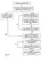
Figure 5 shows a flow diagram of a method for operating the aircraftair conditioning system 10 in a heating mode, i.e., in a case wherein theelectronic control unit 48, for theaircraft region 28 to be air conditioned, has determined a heating demand. In a first step, theelectronic control unit 34 analyses, whether the volume flow of compressed air into the mixingchamber 26 of theair conditioning system 10 exceeds a predetermined minimum value. The volume flow of compressed air into the mixingchamber 26 corresponds to the predetermined minimum value, when theair conditioning unit 14 is operated with its maximum cooling capacity, i.e., cools the compressed air to the lowest possible temperature, and the supply of hot compressed air to the air cooled by theair conditioning unit 14 is interrupted, i.e., thebypass valve 24 disposed in thebypass line 22 is closed. If the volume flow of compressed air into the mixingchamber 26 corresponds to the predetermined minimum value, the control strategy simply is maintained, i.e., no changes in the volume flows of compressed air and recirculation air into the mixingchamber 26 are initiated. - If, however, the volume flow of compressed air into the mixing
chamber 26 exceeds the predetermined minimum value, the volume flow of recirculation air discharged from theaircraft region 28 to be air conditioned into the mixingchamber 26 is increased by increasing the speed of therecirculation fans 30. By increasing the volume flow of typically relatively warm recirculation air into the mixingchamber 26, the actual temperature of the mixed air in the mixingchamber 26 is increased so as to approach the set temperature. - In the next step, the volume flow of compressed air into the mixing
chamber 26 is decreased in dependence on the increase of the volume flow of recirculation air into the mixingchamber 26. Typically, the decrease of the volume flow of compressed air into the mixingchamber 26 is adjusted to the increase of the volume flow of recirculation air into the mixingchamber 26 such that a combined volume flow of recirculation air and compressed air is kept constant. - Upon decreasing the volume flow of compressed air into the mixing
chamber 26 it is possible to first decrease the volume flow of air cooled by theair conditioning unit 14 and to then decrease the supply of hot compressed air to the air cooled by theair conditioning unit 14 in dependence on the decrease of the volume flow of air cooled by theair conditioning unit 14. It is, however, also conceivable to implement a decrease of the volume flow of compressed air into the mixingchamber 26 by first decreasing the supply of hot compressed air to the air cooled by theair conditioning unit 14 and by then decreasing the volume flow of air cooled by theair conditioning unit 14 in dependence on the decrease of the supply of hot compressed air to the air cooled by theair conditioning unit 14. The supply of hot compressed air to the air cooled by theair conditioning unit 14 is be decreased and, if possible, finally interrupted by closing thebypass valve 24. - When the volume flow of compressed air into the mixing
chamber 26 has reached the predetermined minimum value, the increase of the volume flow of recirculation air into the mixingchamber 26 is stopped, as soon as an actual temperature of the mixed air in the mixingchamber 26 corresponds to the set temperature of the mixed air in the mixingchamber 26 which is determined by thecontrol unit 58 based on the heating demand of theaircraft region 28 to be air conditioned. - During the entire control procedure it is possible to increase the volume flow of compressed air into the mixing
chamber 26 from the predetermined minimum value or any other value, if it is determined that the actual temperature of the mixed air in the mixingchamber 26 is below the set temperature of the mixed air in the mixingchamber 26, although the volume flow of recirculation air into the mixingchamber 26 has reached a predetermined maximum value, i.e., therecirculation fans 30 are operated with the maximum speed. Further, the predetermined maximum value of the volume flow of recirculation air into the mixing chamber is determined in dependence on the heating demand of theaircraft region 28 to be air conditioned and the actual temperature of the recirculation air which typically corresponds to the actual temperature in theaircraft region 28 to be air conditioned and which may be measured by means of thetemperature sensor 44. Thus, the volume flow of compressed air into the mixingchamber 26 is increased, if the heating demand of theaircraft region 28 to be air conditioned cannot be met by further increasing the volume flow of recirculation air, for example, due to performance restrictions of therecirculation fans 30 or since the actual temperature of the recirculation air is too low. -
Figure 6 shows a flow diagram of a method for operating theair conditioning system 10 in a cooling mode, i.e., a method for operating the aircraftair conditioning system 10 in case a cooling demand of theaircraft region 28 to be air conditioned is determined by theelectronic control unit 48. In case a cooling demand of theaircraft region 28 to be air conditioned is determined, thecontrol unit 34, in a first step, again analyses whether the volume flow of compressed air into the mixingchamber 26 exceeds the predetermined minimum value or not. If the volume flow of compressed air into the mixingchamber 26 corresponds to the predetermined minimum value, i.e., theair conditioning unit 14 is operated with its maximum cooling capacity and thebypass valve 24 disposed in thebypass line 22 is closed, the control strategy is not changed, i.e., the volume flows of compressed air and recirculation air into the mixingchamber 26 are kept constant. - If, however, the
electronic control unit 34 determines, that the volume flow of compressed air into the mixingchamber 26 exceeds the predetermined minimum value, the volume flow of air cooled by theair conditioning unit 14 of the aircraftair conditioning system 10 into the mixingchamber 26 is decreased. As a result, the actual temperature of the mixed air in the mixingchamber 26 increases. Therefore, the volume flow of hot compressed air which is supplied to the air cooled by theair conditioning unit 14 is decreased in dependence on the decrease of the volume flow of air cooled by theair conditioning unit 14 by closing thebypass valve 24. As a result, the increase of the temperature of the mixed air in the mixingchamber 26 caused by the reduction of the volume flow of air cooled by theair conditioning unit 14 is compensated for. - If possible, the volume flow of air cooled by the
air conditioning unit 14 into the mixingchamber 26 and the volume flow of compressed air which is supplied to the air cooled by theair conditioning unit 14 are decreased until theair conditioning unit 14 is operated with its maximum cooling capacity, i.e., cools the compressed air to the lowest possible temperature, and the supply of hot compressed air to the air cooled by theair conditioning unit 14 is minimized and, if possible, interrupted by closing thebypass valve 24. - If it is determined by the
control unit 34 that hot compressed air is supplied to the air cooled by theair conditioning unit 14, although theair conditioning unit 14 is operated with its maximum cooling capacity, the volume flow of recirculation air into the mixingchamber 26 is increased. Due to the increase of the volume flow of relatively warm recirculating air into the mixingchamber 26, it is possible to decrease the supply of hot compressed air to the air cooled by theair conditioning unit 14 in dependence on the increase of the volume flow of recirculation air into the mixingchamber 26. As a result, the combined volume flow of compressed air into the mixingchamber 26 can further be reduced. The increase of the volume flow of recirculation air into the mixingchamber 26 is stopped, as soon as an actual temperature of the mixed air in the mixingchamber 26 corresponds to the set temperature of the mixed air in the mixingchamber 26 which is determined by thecontrol unit 58 based on the heating demand of theaircraft region 28 to be air conditioned.
Claims (15)
- A method for controlling an aircraft air conditioning system (10), the method comprising the steps:- determining a heating or cooling demand of an aircraft region (28) to be air conditioned, and- controlling a volume flow of recirculation air discharged from the aircraft region (28) to be air conditioned and a volume flow of compressed air into a mixing chamber (26) of the aircraft air conditioning system (10) such that the heating or cooling demand of the aircraft region (28) to be air conditioned is met, while the volume flow of compressed air into the mixing chamber (26) of the aircraft air conditioning system (10) is minimized.
- The method according to claim 1,
wherein, if a heating demand of the aircraft region (28) to be air conditioned is determined and the volume flow of compressed air into the mixing chamber (26) exceeds a predetermined minimum value,- a volume flow of recirculation air discharged from the aircraft region (28) to be air conditioned into the mixing chamber (26) is increased, and- the volume flow of compressed air into the mixing chamber (26) is decreased in dependence on the increase of the volume flow of recirculation air into the mixing chamber (26) until the volume flow of compressed air into the mixing chamber (26) has reached the predetermined minimum value. - The method according to claim 2,
wherein the volume flow of compressed air into the mixing chamber (26) corresponds to the predetermined minimum value, when an air conditioning unit (14) of the aircraft air conditioning system (10) is operated with its maximum cooling capacity, and a supply of hot compressed air to the air cooled by the air conditioning unit (14) is interrupted. - The method according to claim 2 or 3,
wherein, after the volume flow of compressed air into the mixing chamber (26) has reached the predetermined minimum value, the increase of the volume flow of recirculation air into the mixing chamber (26) is stopped, as soon as an actual temperature of the mixed air in the mixing chamber (26) corresponds to a set temperature of the mixed air in the mixing chamber (26), the set temperature of the mixed air in the mixing chamber (26) being associated with the heating demand of the aircraft region (28) to be air conditioned. - The method according to claim 2 or 3,
wherein the volume flow of compressed air into the mixing chamber (26) is increased from the predetermined minimum value, if it is determined that an actual temperature of the mixed air in the mixing chamber (26) is below a set temperature of the mixed air in the mixing chamber (26), although the volume flow of recirculation air into the mixing chamber (26) has reached a predetermined maximum value. - The method according to any one of claims 1 to 5,
wherein, if a cooling demand of the aircraft region (28) to be air conditioned is determined and the volume flow of compressed air into the mixing chamber (26) exceeds a predetermined minimum value,- a volume flow of air cooled by the air conditioning unit (14) of the aircraft air conditioning system (10) into the mixing chamber (26) is decreased, and- a volume flow of hot compressed air which is supplied to the air cooled by the air conditioning unit (14) is decreased in dependence on the decrease of the volume flow of air cooled by the air conditioning unit (14) until the air conditioning unit (14) of the aircraft air conditioning system (10) is operated with its maximum cooling capacity. - The method according to claim 6,
wherein the volume flow of recirculation air into the mixing chamber (26) is increased, if it is determined that hot compressed air is supplied to the air cooled by the air conditioning unit (14), although the air conditioning unit (14) of the aircraft air conditioning system (10) is operated with its maximum cooling capacity, and wherein the volume flow of hot compressed air which is supplied to the air cooled by the air conditioning unit (14) is decreased in dependence on the increase of the volume flow of recirculation air into the mixing chamber (26). - An aircraft air conditioning system (10) comprising:- means for determining a heating or cooling demand of an aircraft region (28) to be air conditioned, and- a control unit (34) which is adapted to control a volume flow of recirculation air discharged from the aircraft region (28) to be air conditioned and a volume flow of compressed air into a mixing chamber (26) of the aircraft air conditioning system (10) such that the heating or cooling demand of the aircraft region (28) to be air conditioned is met, while the volume flow of compressed air into the mixing chamber (26) of the aircraft air conditioning system (10) is minimized.
- The system according to claim 8,
wherein, if a heating demand of the aircraft region (28) to be air conditioned is determined and a volume flow of compressed air into the mixing chamber (26) exceeds a predetermined minimum value, the control unit (34) is adapted to:- increase a volume flow of recirculation air discharged from the aircraft region (28) to be air conditioned into the mixing chamber (26), and- decrease the volume flow of compressed air into the mixing chamber (26) is decreased in dependence on the increase of the volume flow of recirculation air into the mixing chamber (26) until the volume flow of compressed air into the mixing chamber (26) has reached the predetermined minimum value. - The system according to claim 9,
wherein the volume flow of compressed air into the mixing chamber (26) corresponds to the predetermined minimum value, when an air conditioning unit (14) of the aircraft air conditioning system (10) is operated with its maximum cooling capacity, and a supply of hot compressed air to the air cooled by the air conditioning unit (14) is interrupted. - The system according to claim 9 or 10,
wherein the control unit (34) is adapted to stop the increase of the volume flow of recirculation air into the mixing chamber (26), after the volume flow of compressed air into the mixing chamber (26) has reached the predetermined minimum value, as soon as an actual temperature of the mixed air in the mixing chamber (26) corresponds to a set temperature of the mixed air in the mixing chamber (26), the set temperature of the mixed air in the mixing chamber (26) being associated with the heating demand of the aircraft region (28) to be air conditioned. - The system according to claim 9 or 10,
wherein the control unit (34) is adapted to increase the volume flow of compressed air into the mixing chamber (26) from the predetermined minimum value, if it is determined that an actual temperature of the mixed air in the mixing chamber (26) is below a set temperature of the mixed air in the mixing chamber (26), although the volume flow of recirculation air into the mixing chamber (26) has reached a predetermined maximum value. - System according to any one of claims 8 to 12,
wherein, if a cooling demand of the aircraft region (28) to be air conditioned is determined and a volume flow of compressed air into the mixing chamber (26) exceeds a predetermined minimum value, the control unit (34) is adapted to:- decrease a volume flow of air cooled by the air conditioning unit (14) of the aircraft air conditioning system (10) into the mixing chamber (26), and- decrease a volume flow of hot compressed air which is supplied to the air cooled by the air conditioning unit (14) until the air conditioning unit (14) of the aircraft air conditioning system (10) is operated with its maximum cooling capacity. - The system according to claim 13,
wherein the control unit (14) is adapted to decrease the volume flow of hot compressed air which is supplied to the air cooled by the air conditioning unit (14) by closing a bypass valve (24) provided in a bypass line (22) being connected to a compressed air source (12) and opening into a line (20) connecting the air conditioning unit (14) to the mixing chamber (26) downstream of the air conditioning unit (14). - System according to claim 13 or 14,
wherein the control unit (14) is adapted to increase the volume flow of recirculation air into the mixing chamber (26), if it is determined that hot compressed air is supplied to the air cooled by the air conditioning unit (14), although the air conditioning unit (14) of the aircraft air conditioning system (10) is operated with its maximum cooling capacity, and to decrease the volume flow of hot compressed air which is supplied to the air cooled by the air conditioning unit (14) in dependence on the increase of the volume flow of recirculation air into the mixing chamber (26).
Priority Applications (3)
| Application Number | Priority Date | Filing Date | Title |
|---|---|---|---|
| EP12002004.5A EP2664544B1 (en) | 2012-03-21 | 2012-03-21 | Method for controlling an aircraft air conditioning system and aircraft air conditioning system |
| US13/847,337 US9592916B2 (en) | 2012-03-21 | 2013-03-19 | Aircraft air conditioning system and method for controlling an aircraft air conditioning system using a bypass valve |
| CN201310091095.8A CN103318413B (en) | 2012-03-21 | 2013-03-21 | Aircraft air conditioning system and the method for controlling aircraft air conditioning system |
Applications Claiming Priority (1)
| Application Number | Priority Date | Filing Date | Title |
|---|---|---|---|
| EP12002004.5A EP2664544B1 (en) | 2012-03-21 | 2012-03-21 | Method for controlling an aircraft air conditioning system and aircraft air conditioning system |
Publications (3)
| Publication Number | Publication Date |
|---|---|
| EP2664544A2 true EP2664544A2 (en) | 2013-11-20 |
| EP2664544A3 EP2664544A3 (en) | 2013-11-27 |
| EP2664544B1 EP2664544B1 (en) | 2018-05-23 |
Family
ID=49187532
Family Applications (1)
| Application Number | Title | Priority Date | Filing Date |
|---|---|---|---|
| EP12002004.5A Active EP2664544B1 (en) | 2012-03-21 | 2012-03-21 | Method for controlling an aircraft air conditioning system and aircraft air conditioning system |
Country Status (3)
| Country | Link |
|---|---|
| US (1) | US9592916B2 (en) |
| EP (1) | EP2664544B1 (en) |
| CN (1) | CN103318413B (en) |
Cited By (1)
| Publication number | Priority date | Publication date | Assignee | Title |
|---|---|---|---|---|
| CN106136388A (en) * | 2015-03-24 | 2016-11-23 | 华北理工大学 | A kind of self-powered positioning belt |
Families Citing this family (8)
| Publication number | Priority date | Publication date | Assignee | Title |
|---|---|---|---|---|
| CN107548369B (en) * | 2015-04-23 | 2021-01-29 | 空中客车作业有限公司 | Aircraft air conditioning system and method for operating such an aircraft air conditioning system |
| EP3138774A1 (en) * | 2015-09-04 | 2017-03-08 | Airbus Operations GmbH | Aircraft air conditioning system with a reduced process air demand |
| CN106043707B (en) * | 2016-06-29 | 2019-01-11 | 中国商用飞机有限责任公司 | aircraft cabin temperature control system and method |
| US10414505B2 (en) | 2016-09-02 | 2019-09-17 | Embraer S.A. | Aircraft air conditioning system airflow regulation |
| DE102016223531A1 (en) * | 2016-11-28 | 2018-05-30 | Airbus Operations Gmbh | Cabin exhaust supported operable aircraft air conditioning system with a pneumatically powered ambient air compressor |
| RU2699317C1 (en) * | 2018-09-14 | 2019-09-04 | Публичное акционерное общество "Научно-производственная корпорация "Иркут" | Method of aircraft passenger cabin ventilation and air mixer-distributor |
| US11591093B2 (en) * | 2020-04-29 | 2023-02-28 | The Boeing Company | Variable chiller exhaust with crown ventilation |
| US20230373640A1 (en) * | 2022-05-19 | 2023-11-23 | Textron Aviation Inc. | Electric temperature control system for unpressurized aircraft |
Citations (1)
| Publication number | Priority date | Publication date | Assignee | Title |
|---|---|---|---|---|
| DE102008053320A1 (en) | 2008-10-27 | 2010-05-12 | Airbus Deutschland Gmbh | Method and system for controlling an aircraft air conditioning system with optimized fuel consumption |
Family Cites Families (15)
| Publication number | Priority date | Publication date | Assignee | Title |
|---|---|---|---|---|
| US2937011A (en) * | 1957-08-23 | 1960-05-17 | United Aircraft Corp | Aircraft air conditioning system and temperature control means therefor |
| US6655168B2 (en) * | 2001-07-05 | 2003-12-02 | Shimadzu Corporation | Aircraft air conditioner |
| DE10361688B4 (en) * | 2003-12-30 | 2008-04-10 | Airbus Deutschland Gmbh | Device for controlling the supply air temperature of a passenger aircraft |
| DE102004039667A1 (en) * | 2004-08-16 | 2006-03-02 | Airbus Deutschland Gmbh | Air supply device for gas generating system in aircraft, supplies bleeding air from air generation system heat exchanger to on-board inert gas generation system |
| JP4353053B2 (en) * | 2004-10-04 | 2009-10-28 | 株式会社デンソー | Air conditioner for vehicles |
| DE102006007286A1 (en) * | 2006-02-16 | 2007-08-23 | Airbus Deutschland Gmbh | System for improving the air quality in a pressurized cabin of an aircraft |
| DE102006014572B4 (en) * | 2006-03-29 | 2008-08-28 | Airbus Deutschland Gmbh | Device and method for air distribution in a cargo plane |
| US7607318B2 (en) * | 2006-05-25 | 2009-10-27 | Honeywell International Inc. | Integrated environmental control and auxiliary power system for an aircraft |
| DE102006032979A1 (en) * | 2006-07-17 | 2008-01-24 | Liebherr-Aerospace Lindenberg Gmbh | An aircraft air conditioning system and method for operating an aircraft air conditioning system |
| DE102006042584B4 (en) * | 2006-09-11 | 2008-11-20 | Airbus Deutschland Gmbh | Air supply system of an aircraft and method for mixing two air streams in an air supply system |
| US7871038B2 (en) * | 2007-05-17 | 2011-01-18 | The Boeing Company | Systems and methods for providing airflow in an aerospace vehicle |
| DE102007049926A1 (en) * | 2007-10-18 | 2009-04-23 | Airbus Deutschland Gmbh | System and method for air conditioning at least a portion of an aircraft |
| DE102008035123B4 (en) * | 2008-07-28 | 2015-01-15 | Airbus Operations Gmbh | System and method for the air conditioning of an aircraft cabin |
| DE102008053668B4 (en) * | 2008-10-29 | 2010-11-25 | Airbus Deutschland Gmbh | System and method for air conditioning an aircraft cabin with improved cooling performance |
| DE102010054448A1 (en) | 2010-12-14 | 2012-06-14 | Airbus Operations Gmbh | Method and device for controlling an aircraft air conditioning system |
-
2012
- 2012-03-21 EP EP12002004.5A patent/EP2664544B1/en active Active
-
2013
- 2013-03-19 US US13/847,337 patent/US9592916B2/en active Active
- 2013-03-21 CN CN201310091095.8A patent/CN103318413B/en active Active
Patent Citations (1)
| Publication number | Priority date | Publication date | Assignee | Title |
|---|---|---|---|---|
| DE102008053320A1 (en) | 2008-10-27 | 2010-05-12 | Airbus Deutschland Gmbh | Method and system for controlling an aircraft air conditioning system with optimized fuel consumption |
Cited By (1)
| Publication number | Priority date | Publication date | Assignee | Title |
|---|---|---|---|---|
| CN106136388A (en) * | 2015-03-24 | 2016-11-23 | 华北理工大学 | A kind of self-powered positioning belt |
Also Published As
| Publication number | Publication date |
|---|---|
| EP2664544A3 (en) | 2013-11-27 |
| EP2664544B1 (en) | 2018-05-23 |
| US20130248164A1 (en) | 2013-09-26 |
| CN103318413B (en) | 2018-01-16 |
| US9592916B2 (en) | 2017-03-14 |
| CN103318413A (en) | 2013-09-25 |
Similar Documents
| Publication | Publication Date | Title |
|---|---|---|
| US9592916B2 (en) | Aircraft air conditioning system and method for controlling an aircraft air conditioning system using a bypass valve | |
| US8333078B2 (en) | Method and system for controlling an aircraft air conditioning system with optimised fuel consumption | |
| EP2651763B1 (en) | Method and device for controlling an aircraft air conditioning system | |
| EP2998223B1 (en) | Aircraft air conditioning system and method of operating an aircraft air conditioning system | |
| EP2947012B1 (en) | Aircraft air conditioning system and method of its operation | |
| EP2597036B1 (en) | Blended flow air cycle system for environmental control | |
| EP1801009B1 (en) | Integrated control system for combined galley refrigeration unit and cabin air conditioning system | |
| US9221543B2 (en) | Compressor/turbine arrangement, air conditioning unit and method for operating a compressor/turbine arrangement | |
| US9580179B2 (en) | Air conditioning system for an aircraft passenger compartment | |
| EP3173337B1 (en) | Aircraft air conditioning system with ambient air supply and method for operating such an aircraft air conditioning system | |
| US9011219B2 (en) | System and method for air-conditioning an aircraft cabin | |
| EP2799343B1 (en) | Aircraft air-conditioining system | |
| US20130295831A1 (en) | Method for controlling an aircraft air conditioning system during maintenance | |
| JP2019167082A (en) | Carrier air conditioning pack with air cycle assembly | |
| US9689597B2 (en) | Air-conditioning system for an aircraft, and method for an aircraft | |
| US9821914B2 (en) | Aircraft air conditioning system and method of operating an aircraft air conditioning system | |
| EP3138774A1 (en) | Aircraft air conditioning system with a reduced process air demand |
Legal Events
| Date | Code | Title | Description |
|---|---|---|---|
| PUAL | Search report despatched |
Free format text: ORIGINAL CODE: 0009013 |
|
| PUAI | Public reference made under article 153(3) epc to a published international application that has entered the european phase |
Free format text: ORIGINAL CODE: 0009012 |
|
| AK | Designated contracting states |
Kind code of ref document: A2 Designated state(s): AL AT BE BG CH CY CZ DE DK EE ES FI FR GB GR HR HU IE IS IT LI LT LU LV MC MK MT NL NO PL PT RO RS SE SI SK SM TR |
|
| AX | Request for extension of the european patent |
Extension state: BA ME |
|
| AK | Designated contracting states |
Kind code of ref document: A3 Designated state(s): AL AT BE BG CH CY CZ DE DK EE ES FI FR GB GR HR HU IE IS IT LI LT LU LV MC MK MT NL NO PL PT RO RS SE SI SK SM TR |
|
| AX | Request for extension of the european patent |
Extension state: BA ME |
|
| RIC1 | Information provided on ipc code assigned before grant |
Ipc: B64D 13/06 20060101AFI20131022BHEP |
|
| 17P | Request for examination filed |
Effective date: 20140129 |
|
| RBV | Designated contracting states (corrected) |
Designated state(s): AL AT BE BG CH CY CZ DE DK EE ES FI FR GB GR HR HU IE IS IT LI LT LU LV MC MK MT NL NO PL PT RO RS SE SI SK SM TR |
|
| STAA | Information on the status of an ep patent application or granted ep patent |
Free format text: STATUS: EXAMINATION IS IN PROGRESS |
|
| 17Q | First examination report despatched |
Effective date: 20170711 |
|
| REG | Reference to a national code |
Ref country code: DE Ref legal event code: R079 Ref document number: 602012046526 Country of ref document: DE Free format text: PREVIOUS MAIN CLASS: B64D0013060000 Ipc: B64D0013080000 |
|
| GRAP | Despatch of communication of intention to grant a patent |
Free format text: ORIGINAL CODE: EPIDOSNIGR1 |
|
| STAA | Information on the status of an ep patent application or granted ep patent |
Free format text: STATUS: GRANT OF PATENT IS INTENDED |
|
| RIC1 | Information provided on ipc code assigned before grant |
Ipc: B64D 13/06 20060101ALI20171009BHEP Ipc: B64D 13/08 20060101AFI20171009BHEP |
|
| INTG | Intention to grant announced |
Effective date: 20171113 |
|
| RIN1 | Information on inventor provided before grant (corrected) |
Inventor name: KRAKOWSKI, DARIUSZ Inventor name: KELNHOFER, JUERGEN |
|
| GRAS | Grant fee paid |
Free format text: ORIGINAL CODE: EPIDOSNIGR3 |
|
| GRAJ | Information related to disapproval of communication of intention to grant by the applicant or resumption of examination proceedings by the epo deleted |
Free format text: ORIGINAL CODE: EPIDOSDIGR1 |
|
| GRAL | Information related to payment of fee for publishing/printing deleted |
Free format text: ORIGINAL CODE: EPIDOSDIGR3 |
|
| STAA | Information on the status of an ep patent application or granted ep patent |
Free format text: STATUS: EXAMINATION IS IN PROGRESS |
|
| GRAR | Information related to intention to grant a patent recorded |
Free format text: ORIGINAL CODE: EPIDOSNIGR71 |
|
| STAA | Information on the status of an ep patent application or granted ep patent |
Free format text: STATUS: GRANT OF PATENT IS INTENDED |
|
| GRAA | (expected) grant |
Free format text: ORIGINAL CODE: 0009210 |
|
| STAA | Information on the status of an ep patent application or granted ep patent |
Free format text: STATUS: THE PATENT HAS BEEN GRANTED |
|
| INTC | Intention to grant announced (deleted) | ||
| INTG | Intention to grant announced |
Effective date: 20180412 |
|
| AK | Designated contracting states |
Kind code of ref document: B1 Designated state(s): AL AT BE BG CH CY CZ DE DK EE ES FI FR GB GR HR HU IE IS IT LI LT LU LV MC MK MT NL NO PL PT RO RS SE SI SK SM TR |
|
| REG | Reference to a national code |
Ref country code: GB Ref legal event code: FG4D |
|
| REG | Reference to a national code |
Ref country code: CH Ref legal event code: EP |
|
| REG | Reference to a national code |
Ref country code: IE Ref legal event code: FG4D |
|
| REG | Reference to a national code |
Ref country code: DE Ref legal event code: R096 Ref document number: 602012046526 Country of ref document: DE |
|
| REG | Reference to a national code |
Ref country code: AT Ref legal event code: REF Ref document number: 1001327 Country of ref document: AT Kind code of ref document: T Effective date: 20180615 |
|
| REG | Reference to a national code |
Ref country code: NL Ref legal event code: MP Effective date: 20180523 |
|
| REG | Reference to a national code |
Ref country code: LT Ref legal event code: MG4D |
|
| PG25 | Lapsed in a contracting state [announced via postgrant information from national office to epo] |
Ref country code: LT Free format text: LAPSE BECAUSE OF FAILURE TO SUBMIT A TRANSLATION OF THE DESCRIPTION OR TO PAY THE FEE WITHIN THE PRESCRIBED TIME-LIMIT Effective date: 20180523 Ref country code: FI Free format text: LAPSE BECAUSE OF FAILURE TO SUBMIT A TRANSLATION OF THE DESCRIPTION OR TO PAY THE FEE WITHIN THE PRESCRIBED TIME-LIMIT Effective date: 20180523 Ref country code: NO Free format text: LAPSE BECAUSE OF FAILURE TO SUBMIT A TRANSLATION OF THE DESCRIPTION OR TO PAY THE FEE WITHIN THE PRESCRIBED TIME-LIMIT Effective date: 20180823 Ref country code: BG Free format text: LAPSE BECAUSE OF FAILURE TO SUBMIT A TRANSLATION OF THE DESCRIPTION OR TO PAY THE FEE WITHIN THE PRESCRIBED TIME-LIMIT Effective date: 20180823 Ref country code: SE Free format text: LAPSE BECAUSE OF FAILURE TO SUBMIT A TRANSLATION OF THE DESCRIPTION OR TO PAY THE FEE WITHIN THE PRESCRIBED TIME-LIMIT Effective date: 20180523 Ref country code: ES Free format text: LAPSE BECAUSE OF FAILURE TO SUBMIT A TRANSLATION OF THE DESCRIPTION OR TO PAY THE FEE WITHIN THE PRESCRIBED TIME-LIMIT Effective date: 20180523 |
|
| PG25 | Lapsed in a contracting state [announced via postgrant information from national office to epo] |
Ref country code: NL Free format text: LAPSE BECAUSE OF FAILURE TO SUBMIT A TRANSLATION OF THE DESCRIPTION OR TO PAY THE FEE WITHIN THE PRESCRIBED TIME-LIMIT Effective date: 20180523 Ref country code: RS Free format text: LAPSE BECAUSE OF FAILURE TO SUBMIT A TRANSLATION OF THE DESCRIPTION OR TO PAY THE FEE WITHIN THE PRESCRIBED TIME-LIMIT Effective date: 20180523 Ref country code: GR Free format text: LAPSE BECAUSE OF FAILURE TO SUBMIT A TRANSLATION OF THE DESCRIPTION OR TO PAY THE FEE WITHIN THE PRESCRIBED TIME-LIMIT Effective date: 20180824 Ref country code: HR Free format text: LAPSE BECAUSE OF FAILURE TO SUBMIT A TRANSLATION OF THE DESCRIPTION OR TO PAY THE FEE WITHIN THE PRESCRIBED TIME-LIMIT Effective date: 20180523 Ref country code: LV Free format text: LAPSE BECAUSE OF FAILURE TO SUBMIT A TRANSLATION OF THE DESCRIPTION OR TO PAY THE FEE WITHIN THE PRESCRIBED TIME-LIMIT Effective date: 20180523 |
|
| REG | Reference to a national code |
Ref country code: AT Ref legal event code: MK05 Ref document number: 1001327 Country of ref document: AT Kind code of ref document: T Effective date: 20180523 |
|
| PG25 | Lapsed in a contracting state [announced via postgrant information from national office to epo] |
Ref country code: DK Free format text: LAPSE BECAUSE OF FAILURE TO SUBMIT A TRANSLATION OF THE DESCRIPTION OR TO PAY THE FEE WITHIN THE PRESCRIBED TIME-LIMIT Effective date: 20180523 Ref country code: AT Free format text: LAPSE BECAUSE OF FAILURE TO SUBMIT A TRANSLATION OF THE DESCRIPTION OR TO PAY THE FEE WITHIN THE PRESCRIBED TIME-LIMIT Effective date: 20180523 Ref country code: EE Free format text: LAPSE BECAUSE OF FAILURE TO SUBMIT A TRANSLATION OF THE DESCRIPTION OR TO PAY THE FEE WITHIN THE PRESCRIBED TIME-LIMIT Effective date: 20180523 Ref country code: SK Free format text: LAPSE BECAUSE OF FAILURE TO SUBMIT A TRANSLATION OF THE DESCRIPTION OR TO PAY THE FEE WITHIN THE PRESCRIBED TIME-LIMIT Effective date: 20180523 Ref country code: RO Free format text: LAPSE BECAUSE OF FAILURE TO SUBMIT A TRANSLATION OF THE DESCRIPTION OR TO PAY THE FEE WITHIN THE PRESCRIBED TIME-LIMIT Effective date: 20180523 Ref country code: CZ Free format text: LAPSE BECAUSE OF FAILURE TO SUBMIT A TRANSLATION OF THE DESCRIPTION OR TO PAY THE FEE WITHIN THE PRESCRIBED TIME-LIMIT Effective date: 20180523 Ref country code: PL Free format text: LAPSE BECAUSE OF FAILURE TO SUBMIT A TRANSLATION OF THE DESCRIPTION OR TO PAY THE FEE WITHIN THE PRESCRIBED TIME-LIMIT Effective date: 20180523 |
|
| REG | Reference to a national code |
Ref country code: DE Ref legal event code: R097 Ref document number: 602012046526 Country of ref document: DE |
|
| PG25 | Lapsed in a contracting state [announced via postgrant information from national office to epo] |
Ref country code: IT Free format text: LAPSE BECAUSE OF FAILURE TO SUBMIT A TRANSLATION OF THE DESCRIPTION OR TO PAY THE FEE WITHIN THE PRESCRIBED TIME-LIMIT Effective date: 20180523 Ref country code: SM Free format text: LAPSE BECAUSE OF FAILURE TO SUBMIT A TRANSLATION OF THE DESCRIPTION OR TO PAY THE FEE WITHIN THE PRESCRIBED TIME-LIMIT Effective date: 20180523 |
|
| PLBE | No opposition filed within time limit |
Free format text: ORIGINAL CODE: 0009261 |
|
| STAA | Information on the status of an ep patent application or granted ep patent |
Free format text: STATUS: NO OPPOSITION FILED WITHIN TIME LIMIT |
|
| 26N | No opposition filed |
Effective date: 20190226 |
|
| PG25 | Lapsed in a contracting state [announced via postgrant information from national office to epo] |
Ref country code: SI Free format text: LAPSE BECAUSE OF FAILURE TO SUBMIT A TRANSLATION OF THE DESCRIPTION OR TO PAY THE FEE WITHIN THE PRESCRIBED TIME-LIMIT Effective date: 20180523 |
|
| PG25 | Lapsed in a contracting state [announced via postgrant information from national office to epo] |
Ref country code: MC Free format text: LAPSE BECAUSE OF FAILURE TO SUBMIT A TRANSLATION OF THE DESCRIPTION OR TO PAY THE FEE WITHIN THE PRESCRIBED TIME-LIMIT Effective date: 20180523 |
|
| REG | Reference to a national code |
Ref country code: CH Ref legal event code: PL |
|
| PG25 | Lapsed in a contracting state [announced via postgrant information from national office to epo] |
Ref country code: AL Free format text: LAPSE BECAUSE OF FAILURE TO SUBMIT A TRANSLATION OF THE DESCRIPTION OR TO PAY THE FEE WITHIN THE PRESCRIBED TIME-LIMIT Effective date: 20180523 Ref country code: LU Free format text: LAPSE BECAUSE OF NON-PAYMENT OF DUE FEES Effective date: 20190321 |
|
| REG | Reference to a national code |
Ref country code: BE Ref legal event code: MM Effective date: 20190331 |
|
| PG25 | Lapsed in a contracting state [announced via postgrant information from national office to epo] |
Ref country code: CH Free format text: LAPSE BECAUSE OF NON-PAYMENT OF DUE FEES Effective date: 20190331 Ref country code: IE Free format text: LAPSE BECAUSE OF NON-PAYMENT OF DUE FEES Effective date: 20190321 Ref country code: LI Free format text: LAPSE BECAUSE OF NON-PAYMENT OF DUE FEES Effective date: 20190331 |
|
| PG25 | Lapsed in a contracting state [announced via postgrant information from national office to epo] |
Ref country code: BE Free format text: LAPSE BECAUSE OF NON-PAYMENT OF DUE FEES Effective date: 20190331 |
|
| PG25 | Lapsed in a contracting state [announced via postgrant information from national office to epo] |
Ref country code: TR Free format text: LAPSE BECAUSE OF FAILURE TO SUBMIT A TRANSLATION OF THE DESCRIPTION OR TO PAY THE FEE WITHIN THE PRESCRIBED TIME-LIMIT Effective date: 20180523 |
|
| PG25 | Lapsed in a contracting state [announced via postgrant information from national office to epo] |
Ref country code: PT Free format text: LAPSE BECAUSE OF FAILURE TO SUBMIT A TRANSLATION OF THE DESCRIPTION OR TO PAY THE FEE WITHIN THE PRESCRIBED TIME-LIMIT Effective date: 20180924 Ref country code: MT Free format text: LAPSE BECAUSE OF NON-PAYMENT OF DUE FEES Effective date: 20190321 |
|
| PG25 | Lapsed in a contracting state [announced via postgrant information from national office to epo] |
Ref country code: CY Free format text: LAPSE BECAUSE OF FAILURE TO SUBMIT A TRANSLATION OF THE DESCRIPTION OR TO PAY THE FEE WITHIN THE PRESCRIBED TIME-LIMIT Effective date: 20180523 |
|
| PG25 | Lapsed in a contracting state [announced via postgrant information from national office to epo] |
Ref country code: IS Free format text: LAPSE BECAUSE OF FAILURE TO SUBMIT A TRANSLATION OF THE DESCRIPTION OR TO PAY THE FEE WITHIN THE PRESCRIBED TIME-LIMIT Effective date: 20180923 |
|
| PG25 | Lapsed in a contracting state [announced via postgrant information from national office to epo] |
Ref country code: HU Free format text: LAPSE BECAUSE OF FAILURE TO SUBMIT A TRANSLATION OF THE DESCRIPTION OR TO PAY THE FEE WITHIN THE PRESCRIBED TIME-LIMIT; INVALID AB INITIO Effective date: 20120321 |
|
| PG25 | Lapsed in a contracting state [announced via postgrant information from national office to epo] |
Ref country code: MK Free format text: LAPSE BECAUSE OF FAILURE TO SUBMIT A TRANSLATION OF THE DESCRIPTION OR TO PAY THE FEE WITHIN THE PRESCRIBED TIME-LIMIT Effective date: 20180523 |
|
| PGFP | Annual fee paid to national office [announced via postgrant information from national office to epo] |
Ref country code: FR Payment date: 20230324 Year of fee payment: 12 |
|
| PGFP | Annual fee paid to national office [announced via postgrant information from national office to epo] |
Ref country code: GB Payment date: 20230321 Year of fee payment: 12 Ref country code: DE Payment date: 20230321 Year of fee payment: 12 |